


Panasonic Broadcast
AG-HPG10
Menu Information
Basic operations on the setting menus
1 6
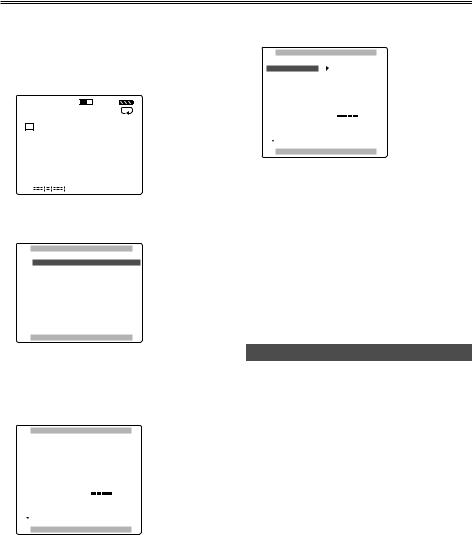
2 Press [MODE] to switch to the thumbnail display off screen.
1 2 |
106 mn |
HD720P
60
C 1
H
C 2
H
3 Press [MENU] to display the menu.
Example:
MAIN MENU
1 . RECORDING SETUP
2 . SW MODE
3 . PLAYBACK FUNCTIONS
4 . AV OUT SETUP
5 . DISPLAY SETUP
6 . CARD FUNCTIONS
7 . OTHER FUNCTIONS
PUSH MENU TO EXIT
1394 UB REGEN |
ON |
UB MODE |
FRM.RATE |
PUSH MENU TO RETURN
7 Press [STILL] to set the item.
To change a numerical value, etc., use [FF] and [REW] to change the setting.
8 To change other items, repeat steps 6 and 7.
To exit the settings, press [MENU] and return to the thumbnail display off screen.
9 To change another function, repeat steps 4 to 7.
To exit the settings, press [MENU] and return to the thumbnail display off screen.
4 Using [STOP] and [PLAY], move the highlighting to the function to be set.
5 Press [STILL] to display the setting item.
Example:
RECORDING SETUP
SYS FORMAT |
|
1080i/60i |
|
SD(480i/576) MODE |
720P/60P |
||
1394 TC REGEN |
720P/30PN |
||
720P/24PN |
|||
TC MODE |
|||
480i/60i |
|||
TCG |
REC RUN |
||
TC PRESET |
|
||
1394 UB REGEN |
ON |
||
UB MODE |
FRM.RATE |
||
PUSH MENU TO RETURN
Initializing the setting menu
You can return (initialize) the setting menu user files to the factory status.
1 Switch the display to the thumbnail display off screen.
2 Press [MENU].
3 Using [STOP], [PLAY] and [STILL], select “OTHER FUNCTIONS” – “USER FILE”
– “INITIAL”.
4 Press [STILL].
The menu settings of the user files currently being used are returned to the factory status.
70

Setting menu configuration
MAIN MENU |
|
RECORDING SETUP |
|
||
|
|
(Pages 72 - 73) |
SW MODE
(Page 74)
PLAYBACK FUNCTIONS
(Page 75)
AV OUT SETUP
(Page 75)
DISPLAY SETUP
(Pages 76 - 77)
CARD FUNCTIONS
(Page 77)
OTHER FUNCTIONS
(Pages 78 - 79)
OPTION MENU
(Page 80)
SYS FORMAT SD(480i/576)MODE 1394 TC REGEN TC MODE
TCG
TC PRESET 1394 UB REGEN UB MODE
UB PRESET 1394 IN PRESET
USER1
USER2
USER3
REPEAT PLAY AUDIO OUT
CMPNT/SDI SEL SDI OUT
SDI METADATA SDI EDH SETUP
VIDEO OUT OSD DATE/TIME LEVEL METER CARD/BATT
P2 CARD REMAIN OTHER DISPLAY LCD BACKLIGHT LCD REVERSE LCD SET
LCD ASPECT
MENU BACK DOWNCON MODE WFM
USER FILE
SD CARD FORMAT
PC MODE BEEP SOUND CLOCK SET TIME ZONE POWER SAVE LANGUAGE SYSTEM FREQ USER FILE OPERATION
LCD OPERATION
1394 STATUS
1394 CONFIG
Menus enclosed in the broken-line frames  are not displayed in the USB HOST mode.
Menu
71

List of setting menus
RECORDING SETUP screen
When the settings are changed using the “SYSTEM FREQ” item (page 79) on the “OTHER FUNCTIONS” screen, whatever has been set on the “RECORDING SETUP” screen will be changed to the initial setting.
Item |
|
Description of settings |
|
|
|
SYS FORMAT |
This is used to set the 1394 input recording format and playback format. |
|
|
(60 Hz) |
|
|
1080/60i, 720/60P, 720/30PN, 720/24PN, 480/60i |
|
|
(50 Hz) |
|
|
1080/50i, 720/50P, 720/25PN, 576/50i |
|
SD(480i/576) MODE |
This is used to set the 1394 input recording video compression format and playback |
|
|
format. |
|
|
DVCPRO50, DVCPRO, DV |
|
1394 TC REGEN |
This is used to select the time code to be recorded when recording signals from a |
|
|
device which is connected to the 1394 connector. |
|
|
ON: |
|
|
The data is recorded using the time code of the signals supplied to the 1394 |
|
|
connector. |
|
|
OFF: |
|
|
The data is recorded using the time code set using the TC MODE item or TCG item. |
|
TC MODE (60 Hz regions |
This is used to select the time code compensation mode when recording the time |
|
only) |
codes of the internal time code generator. |
|
|
DF: |
The drop frame mode is used. |
|
NDF: |
The non-drop frame mode is used. |
TCG |
This is used to set the operation mode for running the time code of the internal time |
|
|
code generator. |
|
|
FREE RUN: |
|
|
The time code runs no matter what operating mode is established. |
|
|
REC RUN: |
|
|
The time code runs only during recording. |
|
TC PRESET |
This is used to set the initial value of the time code to be recorded. |
|
1394 UB REGEN |
This is used to set the recording of the user’s bit when recording input signals from a |
|
|
device which is connected to the 1394 connector. |
|
|
ON: |
|
|
The signals are recorded using the user’s bit of the signals supplied to the 1394 |
|
|
connector. |
|
|
OFF: |
|
|
The signals are recorded using the user’s bit selected by the UM MODE item. |
|
|
When this item has been set to ON, it takes priority over the UB MODE item. |
|
The underlined settings are the factory mode settings.
72
 Loading...