


 Loading...
■ This product is eligible for the P2HD 5 Year Warranty Repair Program. For details,
see page 11.
Operating Instructions
Memory Card Portable Recorder/Player
Model No.
Model No.
AJ-HPM200P AJ-HPM200E
ENGLISH
Excerpted Version
DEUTSCH
Kurzversion
FRANÇAIS Version extraite
ITALIANO
Estratto
ESPAÑOL Versión extractada
This manual is an excerpted version of the full Operating Instructions. For more information, please refer to the PDF manual provided on the supplied CD-ROM.
Dieses Handbuch stellt eine Kurzversion der vollständigen Bedienungsanleitung dar. Weitere Informationen siehe PDF-Datei mit der Bedienungsanleitung auf der mitgelieferten CD-ROM.
Ce manuel est une version extraite du mode d’emploi complet. Pour plus d’informations, consultez le manuel au format PDF fourni sur le CD-ROM.
Questo manuale è un estratto dalle istruzioni per l’uso complete. Per ulteriori informazioni fare riferimento al manuale in formato PDF fornito sul CD-ROM in dotazione.
Este manual es una versión extractada del manual de instrucciones completo. Para más información, consulte el manual en formato PDF proporcionado con el CD-ROM suministrado.
Before operating this product, please read the instructions carefully and save this manual for future use.
• AVCHD capability is available when the optional AVCHD Codec board AJ-YCX250G is installed.
ENGLISH
S0809T0 -P D
Printed in Japan VQT2G72

Read this first! (For AJ-HPM200P)
WARNING:
This equipment must be grounded.
To ensure safe operation, the three-pin plug must be inserted only into a standard three-pin power outlet which is effectively grounded through normal household wiring.
Extension cords used with the equipment must have three cores and be correctly wired to provide connection to the ground. Wrongly wired extension cords are a major cause of fatalities.
The fact that the equipment operates satisfactorily does not imply that the power outlet is grounded or that the installation is completely safe. For your safety, if you are in any doubt about the effective grounding of the power outlet, please consult a qualified electrician.
WARNING:
•To reduce the risk of fire or shock hazard, do not expose this equipment to rain or moisture.
•To reduce the risk of fire or shock hazard, keep this equipment away from all liquids. Use and store only in locations which are not exposed to the risk of dripping or splashing liquids, and do not place any liquid containers on top of the equipment.
CAUTION:
The mains plug of the power supply cord shall remain readily operable.
The AC receptacle (mains socket outlet) shall be installed near the equipment and shall be easily accessible.
To completely disconnect this equipment from the AC mains, disconnect the mains plug from the AC receptacle.
CAUTION:
In order to maintain adequate ventilation, do not install or place this unit in a bookcase, built-in cabinet or any other confined space. To prevent risk of electric shock or fire hazard due to overheating, ensure that curtains and any other materials do not obstruct the ventilation.
CAUTION:
To reduce the risk of fire or shock hazard and annoying interference, use the recommended accessories only.
CAUTION:
To reduce the risk of fire or shock hazard, refer mounting of the optional interface boards to qualified service personnel.
CAUTION:
This apparatus can be operated at a voltage in the range of 100 – 240 V AC.
Voltages other than 120 V are not intended for U.S.A. and Canada.
Operation at a voltage other than 120 V AC may require the use of a different AC plug. Please contact either a local or foreign Panasonic authorized service center for assistance in selecting an alternate AC plug.
CAUTION:
Excessive sound pressure from earphones and headphones can cause hearing loss.
CAUTION:
A coin type battery is installed inside of the unit. Do not store the unit in temperatures over 60 °C (140 °F).
Do not leave the unit in an automobile exposed to direct sunlight for a long period of time with doors and windows closed.
The rating plate is on the underside of this equipment.


 indicates safety information.
2

Read this first! (For AJ-HPM200P) (continued)
IMPORTANT SAFETY INSTRUCTIONS
1)Read these instructions.
2)Keep these instructions.
3)Heed all warnings.
4)Follow all instructions.
5)Do not use this apparatus near water.
6)Clean only with dry cloth.
7)Do not block any ventilation openings. Install in accordance with the manufacturer’s instructions.
8)Do not install near any heat sources such as radiators, heat registers, stoves, or other apparatus (including amplifiers) that produce heat.
9)Do not defeat the safety purpose of the polarized or grounding-type plug. A polarized plug has two blades with one wider than the other. A grounding-type plug has two blades and a third grounding prong. The wide blade or the third prong are provided for your safety. If the provided plug does not fit into your outlet, consult an electrician for replacement of the obsolete outlet.
10)Protect the power cord from being walked on or pinched particularly at plugs, convenience receptacles, and the point where they exit from the apparatus.
11)Only use attachments/accessories specified by the manufacturer.
12)Use only with the cart, stand, tripod, bracket, or table specified by the manufacturer, or sold with the apparatus.
When a cart is used, use caution when moving the cart/apparatus combination to avoid injury from tip-over. 13) Unplug this apparatus during lightning storms or when unused for long periods of time.
14) Refer all servicing to qualified service personnel. Servicing is required when the apparatus has been damaged
S3125A
in any way, such as power-supply cord or plug is damaged, liquid has been spilled or objects have fallen into
the apparatus, the apparatus has been exposed to rain or moisture, does not operate normally, or has been dropped.
Notice (U.S.A. only):
This product has a fluorescent lamp that contains mercury. Disposal may be regulated in your community due to environmental considerations. For disposal or recycling information, please contact your local authorities, or the Electronic Industries Alliance: http://www.eiae.org.
<For USA-California Only>
This product contains a CR Coin Cell Lithium Battery which contains Perchlorate Material - special handling may apply.
See www.dtsc.ca/gov/hazardouswaste.perchlorate.
3

Read this first! (For AJ-HPM200P) (continued)
FCC NOTICE (U.S.A.)
Declaration of Conformity
Model Number: |
AJ-HPM200P |
Trade Name: |
Panasonic |
Responsible Party: |
Panasonic Corporation of North America |
|
One Panasonic Way, Secaucus, NJ07094 |
Support contact: |
Panasonic Broadcast & Television Systems Company |
1-800-524-1448
This device complies with Part 15 of FCC Rules.
Operation is subject to the following two conditions:
(1)This device may not cause harmful interference, and (2) this device must accept any interference received, including interference that may cause undesired operation.
To assure continued compliance, follow the attached installation instructions and do not make any unauthorized modifications.
Note:
This equipment has been tested and found to comply with the limits for a class B digital device, pursuant to Part 15 of the FCC Rules. These limits are designed to provide reasonable protection against harmful interference in a residential installation. This equipment generates, uses, and can radiate radio frequency energy, and if not installed and used in accordance with the instructions, may cause harmful interference to radio communications. However, there is no guarantee that interference will not occur in a particular installation. If this equipment does cause harmful interference to radio or television reception, which can be determined by turning the equipment off and on, the user is encouraged to try to correct the interference by one of the following measures:
•Reorient or relocate the receiving antenna.
•Increase the separation between the equipment and receiver.
•Connect the equipment into an outlet on a circuit different from that to which the receiver is connected.
•Consult the dealer or an experienced radio/TV technician for help.
The user may find the booklet “Something About Interference” available from FCC local regional offices helpful.
Warning:
To assure continued FCC emission limit compliance, follow the attached installation instructions and the user must use only shielded interface cables when connecting to host computer or peripheral devices. Also, any unauthorized changes or modifications to this equipment could void the user’s authority to operate this device.
4
Read this first! (For AJ-HPM200E)
WARNING:
This equipment must be earthed.
To ensure safe operation, the three-pin plug must be inserted only into a standard three-pin power point which is effectively earthed through normal household wiring.
Extension cords used with the equipment must have three cores and be correctly wired to provide connection to the earth. Wrongly wired extension cords are a major cause of fatalities.
The fact that the equipment operates satisfactorily does not imply that the power point is earthed or that the installation is completely safe. For your safety, if you are in any doubt about the effective earthing of the power point, please consult a qualified electrician.
WARNING:
•To reduce the risk of fire or shock hazard, do not expose this equipment to rain or moisture.
•To reduce the risk of fire or shock hazard, keep this equipment away from all liquids. Use and store only in locations which are not exposed to the risk of dripping or splashing liquids, and do not place any liquid containers on top of the equipment.
CAUTION:
To reduce the risk of fire or shock hazard and annoying interference, use the recommended accessories only.
CAUTION:
To reduce the risk of fire or shock hazard, refer mounting of the optional interface boards to qualified service personnel.
CAUTION:
In order to maintain adequate ventilation, do not install or place this unit in a bookcase, built-in cabinet or any other confined space. To prevent risk of electric shock or fire hazard due to overheating, ensure that curtains and any other materials do not obstruct the ventilation.
CAUTION:
The mains plug of the power supply cord shall remain readily operable.
The AC receptacle (mains socket outlet) shall be installed near the equipment and shall be easily accessible.
To completely disconnect this equipment from the AC mains, disconnect the mains plug from the AC receptacle.
CAUTION:
Excessive sound pressure from earphones and headphones can cause hearing loss.
CAUTION:
Do not remove panel covers by unscrewing them. To reduce the risk of electric shock, do not remove the covers. No user serviceable parts inside.
Refer servicing to qualified service personnel.
CAUTION:
A coin type battery is installed inside of the unit. Do not store the unit in temperatures over 60 °C (140 °F).
Do not leave the unit in an automobile exposed to direct sunlight for a long period of time with doors and windows closed.
The rating plate is on the underside of this equipment.


 indicates safety information.
5
Read this first! (For AJ-HPM200E) (continued)
Caution for AC Mains Lead
FOR YOUR SAFETY PLEASE READ THE FOLLOWING TEXT CAREFULLY.
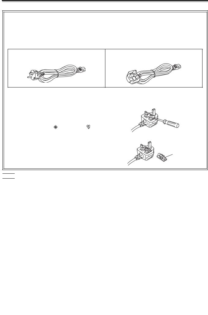
This product is equipped with 2 types of AC mains cable. One is for continental Europe, etc. and the other one is only for U.K.
Appropriate mains cable must be used in each local area, since the other type of mains cable is not suitable.
FOR CONTINENTAL EUROPE, ETC. |
FOR U.K. ONLY |
Not to be used in the U.K.
FOR U.K. ONLY
This appliance is supplied with a moulded three pin |
How to replace the fuse |
mains plug for your safety and convenience. |
1.Open the fuse compartment with a screwdriver. |
A 13 amp fuse is fitted in this plug.
Should the fuse need to be replaced please ensure that the replacement fuse has a rating of 13 amps and that it is approved by ASTA or BSI to BS1362.
Check for the ASTA mark |
or the BSI mark |
on the |
body of the fuse. |
|
|
2.Replace the fuse.
If the plug contains a removable fuse cover you must ensure that it is refitted when the fuse is replaced.
If you lose the fuse cover the plug must not be used until
a replacement cover is obtained. Fuse A replacement fuse cover can be purchased from your
local Panasonic Dealer.


 indicates safety information.
EEE Yönetmeliğine Uygundur.
EEE Complies with Directive of Turkey.
indicates safety information.
6

Read this first! (For AJ-HPM200E) (continued)
EMC NOTICE FOR THE PURCHASER/USER OF THE APPARATUS
1. Applicable standards and operating environment (AJ-HPM200E)
The apparatus is compliant with:
•standards EN55103-1 and EN55103-2 1996.11, and
•electromagnetic environments E1, E2, E3 and E4
2.Pre-requisite conditions to achieving compliance with the above standards
<1> Peripheral equipment to be connected to the apparatus and special connecting cables
•The purchaser/user is urged to use only equipment which has been recommended by us as peripheral equipment to be connected to the apparatus.
•The purchaser/user is urged to use only the connecting cables described below.
<2> For the connecting cables, use shielded cables which suit the intended purpose of the apparatus.
•Video signal connecting cables
Use double shielded coaxial cables, which are designed for 75-ohm type high-frequency applications, for SDI (Serial Digital Interface).
Coaxial cables, which are designed for 75-ohm type high-frequency applications, are recommended for analog video signals.
•Audio signal connecting cables
If your apparatus supports AES/EBU serial digital audio signals, use cables designed for AES/EBU. Use shielded cables, which provide quality performance for high-frequency transmission applications, for analog audio signals.
•Other connecting cables (IEEE1394, USB)
Use shielded cables, which provide quality performance for high-frequency applications, as connecting cables.
•When connecting to the DVI signal terminal, use a cable with a ferrite core.
•If your apparatus is supplied with ferrite core(s), they must be attached on cable(s) following instructions in this manual.
3.Performance level
The performance level of the apparatus is equivalent to or better than the performance level required by these standards.
However, the apparatus may be adversely affected by interference if it is being used in an EMC environment, such as an area where strong electromagnetic fields are generated (by the presence of signal transmission towers, cellular phones, etc.). In order to minimize the adverse effects of the interference on the apparatus in cases like this, it is recommended that the following steps be taken with the apparatus being affected and with its operating environment:
1.Place the apparatus at a distance from the source of the interference.
2.Change the direction of the apparatus.
3.Change the connection method used for the apparatus.
4.Connect the apparatus to another power outlet where the power is not shared by any other appliances.
To remove the battery
Back-up Battery (Lithium Battery)
• For the removal of the battery for disposal at the end of its service life, please consult your dealer.
7
•SDHC logo is a trademark.
•miniSD logo is a trademark.
•“AVCHD” and “AVCHD” logo are trademarks of Panasonic Corporation and Sony Corporation.
•Microsoft®, Windows® and Windows Vista® are registered trademarks or trademarks of Microsoft Corporation of the United States and/or other countries.
•Microsoft product screen shots reprinted with permission from Microsoft Corporation.
•Names of products, brands, etc., appearing in this manual are trademarks or registered trademarks of their respective owners.
•This product is licensed under the AVC Patent Portfolio License for the personal and non-commercial use of the following activities of a consumer but no license is granted or implied for any other use.
-Encoding video in compliance with the AVC standard (hereafter referred to as “AVC video”).
-Decoding AVC video that was encoded by a consumer engaged in a personal and non-commercial activity.
-Decoding AVC video that was obtained from a video provider licensed to provide AVC video. Additional information may be obtained from MPEG LA, LLC (http://www.mpegla.com).
-Using this product to make recordings on SD memory cards for distribution to end users for a commercial purpose requires a separate license agreement from MPEG-LA. End user refers to a person or organization using content for private purposes.
Illustrations in this manual
• Note that illustrations of the unit and menu screens may differ from the ones you actually see.
Page references
• In this manual, references to pages are indicated as: ( page 00, PDF page 00).
Terminology
•The term “SD memory card” will be used below as a generic for SD and SDHC memory cards.
•A memory card with the “P2” logo (for example the separately sold AJ-P2C064AG) is referred to as a “P2 card.”
•A hard disk drive (HDD) is referred to as a “hard disk.”
•A continuous video recording created during a single recording is referred to as a “clip.”
•The state when the THUMBNAIL and PLAYLIST buttons are off is referred to as the “recording/playback mode.” (Refer to page 30.)
8

 Contents
Introduction
Clip Management
Setup
Read this first! (For AJ-HPM200P) .............................................................. |
2 |
Read this first! (For AJ-HPM200E) .............................................................. |
5 |
Accessories ............................................................................................... |
11 |
Included Accessories ................................................................................. |
11 |
Optional Accessories .................................................................................. |
11 |
Opening and Closing the Top Panel .......................................................... |
12 |
Features ..................................................................................................... |
13 |
Control Reference Guide ........................................................................... |
16 |
Audio and Video Controller ......................................................................... |
16 |
GUI Operations ........................................................................................... |
20 |
Panel Control Unit and Card Slots .............................................................. |
24 |
LCD Panel ................................................................................................... |
25 |
Rear Panel ................................................................................................... |
26 |
Side Panel ................................................................................................... |
29 |
Moving Between Screens and Menu Operations ....................................... |
30 |
Operating Modes ........................................................................................ |
30 |
Menu Operations ......................................................................................... |
31 |
Recording, Playback and P2 Card Handling .............................................. |
32 |
Insert a P2 Card .......................................................................................... |
32 |
Recording and Playback ............................................................................. |
32 |
Removing P2 Cards .................................................................................... |
34 |
Preventing Accidental Deletion ................................................................... |
34 |
Connections ............................................................................................... |
35 |
Example of Connections in 23.98/24/29.97/25 Hz Mode ............................ |
35 |
Example of Connections for Remote Control .............................................. |
35 |
Jog and Shuttle Operations Using the Search Dial .................................... |
36 |
Jog Mode .................................................................................................... |
36 |
Shuttle Mode (SHTL Mode) ......................................................................... |
36 |
Thumbnail and Clip Management .............................................................. |
38 |
Thumbnail Screen Names and Functions ................................................... |
39 |
Thumbnail Menu .......................................................................................... |
42 |
Unit Setup .................................................................................................. |
43 |
Changing Settings ..................................................................................... |
44 |
Change Operations ..................................................................................... |
44 |
Using a Lock to Protect the User Setting File ............................................. |
45 |
Returning to Factory Defaults (Initial Settings) ............................................ |
45 |
Setup Menu ................................................................................................. |
46 |
Error Messages ....................................................................................................................................................... |
48 |
WARNING Information Display ....................................................................................................................................... |
49 |
Specifications .......................................................................................................................................................... |
58 |
9

■ Information on software for this product
1.Included with this product is software licensed under the GNU General Public License (GPL) and GNU Lesser General Public License (LGPL), and users are hereby informed that they have the right to obtain, change and redistribute the source codes of this software.
Details on GPL and LGPL can be found on the installation CD provided with the unit. Refer to the folder called “LDOC”. (Details are given in the original (English-language) text.)
To obtain the source codes, go to the following home page: https://eww.pavc.panasonic.co.jp/pro-av/
The manufacturer asks users to refrain from directing inquiries concerning the source codes they have obtained and other details to its representatives.
2.Included with this product is software which is licensed under MIT-License.
Details on MIT-License can be found on the installation CD provided with the unit. Refer to the folder called “LDOC”. (Details are given in the original (English-language) text.)
3.This product contains software licensed under the OpenSSL License and SSLeay License. Details on OpenSSL and SSLeay can be found on the installation CD provided with the unit. Refer to the folder called "LDOC". (Details are given in the original (English language) text.)
■Panasonic makes no guarantees for your recordings
Please understand that Panasonic makes no guarantees for your recordings in cases where video and/or audio were not recorded as you intended due to problems with this unit, P2 cards, or SD memory cards.
■ What to remember when throwing memory cards away or transferring them to others
Formatting memory cards or deleting data using the functions of the unit or a computer will merely change the file management information: it will not completely erase the data on the cards. When throwing these cards away or transferring them to others, either physically destroy them or use a data deletion program for computers (commercially available) to completely erase the data. Users are responsible for managing the data on their memory cards.
■ Place of Installation
Do not install this unit in a location exposed to direct sunlight as this may deform the cabinet or damage the LCD screen.
■ Liquid crystal displays
•While 99.99% or more of the pixels on an LCD screen will function normally, 0.01% may either be dead or constantly lit (seen as red, blue or green dots). This is not a malfunction.
•There may be some unevenness on the screen depending on the image displayed.
•Wiping or rubbing the LCD screen with a rough cloth may damage it.
•Leaving an unchanging image on the screen for a long period of time may create a temporary afterimage (burn-in).
•LCD response and brightness vary with ambient temperature.
•In a high-temperature and high-humidity location, the LCD panel characteristics may change and result in uneven image quality.
10
Accessories
Included Accessories |
|
Power cable................................................... |
1 (AJ-HPM200P) |
|
2 (AJ-HPM200E) |
CD-ROM ................................................................................ |
1 |
NOTE:
•Be sure to appropriately dispose of the packing material when you have unpacked the product.
•Consult your supplier regarding purchase of accessories.
 Optional Accessories
•AVCHD Codec board AJ-YCX250G
NOTE:
•Do not use optional boards other than the above product.
•Have your supplier install optional boards.
P2HD 5 Year Warranty Repair Program*1
Thank you for purchasing this Panasonic P2HD device.
Register as a user for this device to receive a special service warranty up to five years of free warranty repairs.
Customers who register as users on the website will receive an extended warranty repair valid for up to five years.
|
|
|
1st year |
2nd year |
|
3rd year |
4th year |
|
5th year*5 |
|
|
P2HD device*2 |
Basic warranty*3 |
|
Extended warranty repair*4 |
|
|||
|
|
|
|
|
|
|
|
||
|
|
*1: Please note that this extended warranty is not available in some countries/regions. *2: Not all models eligible for extended warranty coverage. |
|||||||
|
|
*3: The basic warranty period may vary depending on the country/region. *4: Not all repair work is covered by this extended warranty. |
|||||||
|
|
*5: The maximum warranty period may be adjusted depending on the number of hours the device has been used. |
|
||||||
|
|
|
|
Free 5 years of Warranty Repairs |
|
||||
|
|
|
|
Make sure to save the “Registration Notice” e-mail |
|
||||
Purchase |
Register online |
“Registration Notice” |
during the warranty period. |
|
|
|
|||
|
|
|
|
|
|
||||
P2 product |
within 1 month |
e-mail sent |
|
|
|
|
|
|
|
Details about user registration and the extended warranty:  http://panasonic.biz/sav/pass_e
Please note, this is a site that is not maintained by Panasonic Canada Inc. The Panasonic Canada Inc. privacy policy does not apply and is not applicable in relation to any information submitted. This link is provided to you for convenience.
Accessories 11

Opening and Closing the Top Panel
NOTE:
•Take care to avoid pinching your fingers when opening and closing the top panel.
•Check that the card lock is set to on before closing the top panel. Never use force to close it when the lock is not set to on as this will damage the unit.
 Closing the top panel
1 Make sure the EJECT button is folded downwards.
If not folded, fold the EJECT button to the right and set the
card lock to on.
 Opening the top panel
1 Pull out the handle, then pull the top of the lever towards you to release the lock.
|
|
|
OFF |
ON |
|
C |
AR |
|
|
D L |
|
|
|
OCK |


2 Free the bottom of the lever. Then hold the top panel and raise it to open.

NOTE:
• Do not expose the lever to excessive force.
2 Close the top panel and engage the bottom of the lever with the receptacle in the lower portion of the panel assembly.
3 While making sure that the bottom of the lever has been properly seated, press the top of the lever towards the rear to lock it.
12 Opening and Closing the Top Panel
Introduction
Features
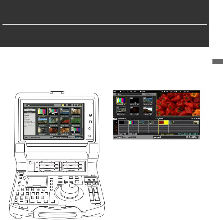
The AJ-HPM200 is a portable memory card recorder/player equipped with six P2 card slots and a 9-inch color LCD monitor. It allows you to record and play back audio and video in the compressed DVCPRO HD, DVCPRO50, DVCPRO, DV and AVC-Intra formats on the six P2 cards, to edit P2 card and hard disk video data and edit using an external VTR as a player. The AJ-HPM200 comes with the following features.
Introduction
Introduction: Features 13
■ Connecting a P2 Card Camera
A P2 card recorded in a P2 camera recorder plugs directly into a PC card slot in this unit for immediate access. The P2 card is a semiconductor memory card that Panasonic developed for professional AV use.
■ AVC-Intra standard feature
The AVC-Intra codec is provided as a standard feature.
An Intra-Frame compression format based on the H.264 video compression standard makes possible a high compression rate and high-quality image.
The AVC-Intra codec for this product is compatible with the following two formats.
AVC-Intra 100: High-quality video supporting full-bit HD AVC-Intra 50: Low-rate and low-cost operation
■Built-in up/down/cross converter for output and up converter for input
The AJ-HPM200 provides a built-in up/down/cross converter for output as standard. It also up-converts composite and SD-SDI input signals to record in the same HD format as the system.
NOTE:
•The cross converter function is not available during up-conversion recording.
•SD closed caption signals during up-conversion recording are recorded in the 608 HD (VANC) signal format (59.94 Hz only).
•Closed caption signals are not output during playback or downand cross-conversion.
•Nor are closed caption signals output during playback of upconverted SD signals.
■ Frame rate conversion
Recording input from variable frame-rate cameras at 24PN (Native), the unit is also capable of playing back cards recorded at 24 fps and converting the output to 1080/24 PsF. It can also record input from a variable frame-rate camera at 25PN (Native).
NOTE:
•Do not use cards that have been edited or contain clips shot in different formats as the loss of management data may prevent normal playback.
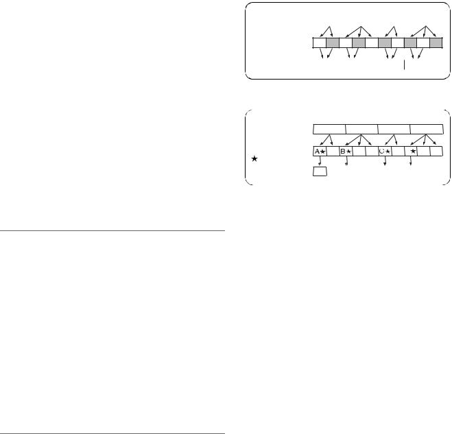
■ Native recording
The unit provides support for native recording, a mode that records only active frames. This provides longer recording time when a VariCam, AJ-HPX2000/2100 or AJ-HPX3000 is connected to the HD-SDI IN connector. Variable frame rate (VFR) recording becomes possible by connecting a VariCam.
●Native recording defined
Native recording extracts only the active frames during 1080i AVC-Intra recording as well as 720P DVCPRO HD and AVC-Intra recording. At 720P, this lengthens the recording time 2 to 2.5 times over pull-down recording.
14 Introduction: Features
During native recording at a 59.94 Hz or 50 Hz setting in setup menu No. 25 (SYSTEM FREQ), the unit produces pull-down output.
Example of 1080-24PN (Native)
Camera video |
A |
B |
C |
D |
2:3 pull-down |
Ao Ae Bo Be Bo Ce Co De Do De |
Native recording |
A |
B |
|
|
C |
D |
|
||||
Example of 720-24PN (Native) |
|
|
|
|
|
|
|
|
|||
Camera video |
A |
|
B |
|
|
|
C |
|
D |
|
|
2:3 pull-down |
A |
|
B |
B |
|
C D |
|
D |
D |
||
Active frames |
|
|
|
|
|
|
|
|
|
|
|
Native recording |
A |
|
|
|
|
|
|
|
|
|
|
B |
|
|
C |
|
|
D |
|
|
|
||
|
|
|
|
|
|
|
|
|
|
||
■ Thumbnails for managing clips visually
The 9-inch color LCD monitor displays video clips (thumbnails) stored on a P2 card. The viewer can select the thumbnails he wants to see and change the order in which they appear.
Clips can be selected from the thumbnail list for immediate playback. The list also provides quick access to other clip management operations such as copying and deleting, adding shot marks and text memos as well as confirming and editing clip data.
■ Expanded high-speed hard disk interface
●High-speed eSATA interface
The unit now supports hard disks using the eSATA interface, which is faster than the regular USB interface. This interface provides faster backup of video data on a P2 card to hard disk and can restore hard disk data to a P2 card.
●Playback (best effort) and playlist editing of hard disk video data
Video data on a hard disk can be viewed as thumbnails or a smooth *1 video stream. A protective feature ensures a continuous audio output even if reading performance drops due to use of a slow hard disk or through interference such as vibrations.
Playback of hard disk video data *1 enables editing of video on a hard disk in the same way as editing video on a P2 card. Playback *1 of hard disk video data enables direct editing.
*1: This does not guarantee playback without frame skipping.

■ Gigabit Ethernet network supported
●FTP client
In the thumbnail screen, this network allows to select video stored on a P2 card or external hard disk and transfer it at high speed via an FTP server on the Internet. Video stored on an FTP server can be displayed and selected as a thumbnail for downloading to a P2 card or external hard disk. And SD memory card data can be sent by the card to and from an FTP server. The network also enables transmission of data encrypted using SSH.
●Browser
A browser mode enables the user to browse web sites with web page authentication required for connecting to the Internet.
●FTP server
The unit can operate as an FTP server allowing a computer or other FTP client to load video files stored on P2 cards or in an external hard disk.
●SAMBA server
When connected to a Windows computer or other network computer, the unit can operate as a SAMBA server to load video files stored on P2 cards or in an external hard disk.
●HTTP server
Using the unit as an HTTP server allows you to view lists of video data from a browser on a computer, view metadata, and play back proxy data.
■ Editing and GUI
●Independent audio and video editing
Any video and audio (4ch) tracks can be independently selected for editing.
●Insert editing and overwrite editing
Two types of editing are available: insert editing, in which new events are added between two editing events and overwrite editing, in which a new event overwrites an event.
●Two screens for editing material and playlist video
Editing material (player) and playlist (recorder) video appear in two screens at all times. A timeline indicating editing status appears simultaneous with these screens for intuitive editing.
●Capability to edit both tape and hard disk material
Use of a VTR or similar device with an RS-422A interface as player makes possible linear-like editing (deck-to-deck editing). Video data transferred to an eSATA or USB hard disk can also be edited.
●Function for adjusting audio level (variable) of any section Preview and audio level adjustments make it possible to operate the audio playback fader for the required audio section to adjust the audio level (variable).
●Display and playback of player thumbnails
A player using P2 cards or a hard disk can display player thumbnails. Thumbnails can be set to limit the clips used by the player to the required clips.
■Audio AES/EBU input and output supported (16 bit, 48 kbps/4 ch)
The unit comes with a 4-channel AES/EBU input and output interface as standard. This enables interfacing with digital audio equipment and digital VTRs using a 48 kHz sampling rate.
■ AVCHD option (AJ-YCX250G)
Installation of the AJ-YCX250G, an optional AVCHD codec board, will enable recording and playback of the AVCHD format on SD memory cards.
This makes the following possible.
•Dubbing AVCCAM recorded clips onto a P2 card in the DVCPROHD or AVC-Intra format, playlist editing of such clips and ingesting such clips to non-linear editor.
•Dubbing P2 card clips recorded on a P2HD camerarecorder to an SD memory card in the AVCHD format.
•HD-SDI or other external input can be recorded as DVCPROHD or AVC-Intra to a P2 card simultaneous with recording of the same input in AVCHD format video on an SD memory card.
■ Waveform and vector display
The LCD screen can display either video waveform or vector waveform.
During up-conversion, a waveform is displayed after upconversion.
NOTE:
• A waveform is not displayed when there is no input signal.
■ HD-SDI remote
When the unit is connected to a camera-recorder with an external device control, start and stop of recording of HD-SDI signal input can be automatically controlled through recording start and stop signals in the input.
■ USB keyboard
A USB keyboard can be connected to enable the following functions.
●Entry and editing of clip metadata
●Network setup, browser
NOTE:
• Some USB keyboards may not enable normal input.
■VANC data recording/playback function (59.94 Hz, 50 Hz only)
Recording and playback of ancillary data (VANC data) of up to 5760 bytes per frame conforming to SMPTE 291M is superimposed on the vertical blanking area of video.
Introduction
Introduction: Features 15
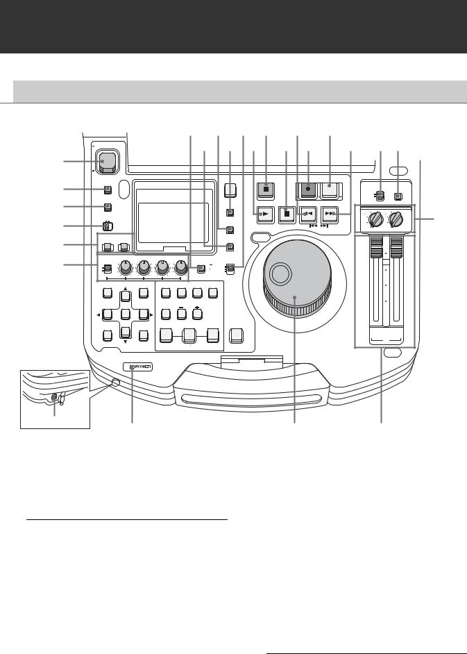
Control Reference Guide
 Audio and Video Controller
1
2
3
4
5
6
24 |
22 |
20 |
18 |
16 |
14 |
12 |
11 |
|
ON |
23 |
21 |
19 |
17 |
15 |
13 |
||
POWER |
|
|
|
|
|
|
|
|
OFF |
|
|
|
|
|
PREVIEW |
|
|
METER |
|
|
STOP |
|
REC |
|
|
|
PLAYER |
|
A.LEVEL REC |
|
|
||||
FULL/FINE |
|
|
|
|
|
CONTROL |
MODE |
|
|
|
|
|
|
|
|||
MONITOR |
|
|
|
|
|
REMOTE |
|
|
SOURCE SELECT |
|
STILL/ |
|
LOCAL |
|
|
||
SELECT |
|
REW |
FF |
|
|
|||
COUNTER |
PLAY |
PAUSE |
|
|
||||
|
|
|
||||||
|
|
|
|
3 |
|
4 |
||
METER SELECT |
|
|
|
|
|
|
||
|
RESET |
|
|
|
1 3 |
2 4 |
10 |
|
CH 1-4 CH 5-8 |
|
|
|
|
1 |
2 |
||
|
|
|
REVIEW |
|
PREV |
NEXT |
|
|
|
|
|
1 CLIP PLAY |
|
|
UNITY |
UNITY |
|
INPUT SELECT |
|
|
|
|
|
|
|
NEW |
|
VIDEO AUDIO |
|
|
|
|
|
|
TC PRESET |
|
|
|
|
|
|
|
|
|
|
|
10 |
CH 1 |
CH 2 |
CH 3 |
CH 4 |
TEXT INT |
PROP |
|
|||
TCG |
|
||||||||
REC |
|
|
|
MEMO |
|
REGEN |
0 |
||
|
|
|
|
|
|||||
VAR |
|
|
|
|
|
|
|
|
|
|
|
|
|
|
|
PRESET |
|
|
|
UNITY |
|
|
|
|
|
|
|
|
|
|
|
|
MARKER |
EXT |
|
|
|||
|
|
|
|
|
10 |
||||
|
|
|
|
|
|
||||
|
|
|
|
|
|
|
|
|
|
THUMBNAIL |
PLAYLIST |
VIDEO |
A1 |
A2 |
GO TO |
|
|
||
|
|
|
|
|
|
|
|
|
20 |
|
|
EDIT MODE |
A3 |
A4 |
A.DUB |
|
|
||
SET |
|
LAST X |
TRIM |
MODE |
|
30 |
|||
|
|
|
|
|
|||||
MULTI |
|
DELETE |
SLOT SELECT |
|
OUT |
|
|
||
SEL |
MENU |
IN |
ENTRY |
|
|
|
|||
EXIT |
|
|
|
|
|
|
CH |
CH |
|
|
|
|
|
|
|
|
|
1/3 |
2/4 |
CANCEL/PF |
DIAG |
SLOT CLIP |
|
|
ALL CLIP |
|
PB |
||
CLIP LIST |
SHIFT |
|
|||||||
|
OPERATION |
PF1 |
|
PF2 |
|
|
PF3 |
PF4 |
|
Headphones jack
7
1. POWER switch
Turns the power on and off.
2. METER (FULL/FINE) selector button
8 |
9 |
3. AUDIO MONITOR SELECT button
Switches the audio signals to be output to the MONITOR L/R connectors and the headphones jack. Each press of the button switches the output signals to the MONITOR L/R connectors and the headphones jack as described below.
Switches the scale of the audio level meter.
FULL mode: |
Selects the standard scale |
||
|
(– ∞ to 0 dB range) |
||
|
|
|
|
FINE mode: |
Selects a scale divided into 0.5 dB |
||
|
increments. |
||
|
“ |
|
” indicates reference level (as |
|
|
||
|
set in setup menu) on a scale |
||
|
divided into 0.5 dB increments. |
||
|
|
|
|
When the METER |
[CH1 / 2] [CH3 / 4] |
SELECT switch is set to |
[CH1 / 1] [CH2 / 2] |
CH 1 to 4: |
[CH3 / 3] [CH4 / 4] |
|
[CH1+2 / 1+2] |
|
[CH3+4 / 3+4] |
|
[CH1+3 / 2+4] |
|
|
When the METER |
[CH5 / 6] [CH7 / 8] |
SELECT switch is set to |
[CH5 / 5] [CH6 / 6] |
CH 5 to 8: |
[CH7 / 7] [CH8 / 8] |
(selectable only with HD |
[CH5+6 / 5+6] |
format) |
[CH7+8 / 7+8] |
|
[CH5+7 / 6+8] |
The L/R lamps in the audio level meter indicate which signal is selected.
16 Introduction: Control Reference Guide

4. METER SELECT switch
Switches to CH1-4 or CH5-8 in the audio meter and the
monitor.
5. INPUT SELECT buttons
Switch between video and audio input signals.
VIDEO: Press the VIDEO button to open a screen for selecting input signal. Pressing the button when the screen is open enables selection of CMPST, HDSDI, SDSDI, 1394 or SG input. When SG is selected, the signal switches to the internal signal selected in setup menu No. 601 (VIDEO INT SG).
Selecting composite or SD SDI when setup menu No. 020 (SYS FORMAT) is set to 1080i or 720p automatically up-converts SD to HD when recording. The unit indicates this as CMPST (U/C) and SDSDI (U/C).
AUDIO: Press the AUDIO button to open a screen for selecting input signal. Pressing the button when the screen is open enables selection of ANALOG, AES/EBU, SDI or SG input.
NOTE:
•When VIDEO is set to 1394, AUDIO is automatically set to 1394.
•The selected input item blinks when there is no input signal.
•Press the INPUT SELECT button once to show the current setting. When you do not want to change the setting, press the EXIT button or wait for 3 seconds to allow the display of the current setting to vanish.
6.AUDIO REC VOL SEL switch
UNITY/VAR switch
UNITY: Records the audio signals at a fixed level regardless of the positions of the audio level controls.
VAR: Records audio signals at the level set with the audio level controls.
Audio level controls
Use these controls to adjust the recording levels of the audio signals (CH1/CH2/CH3/CH4). However, the recording level cannot be adjusted during 1394 input.
7. POWER indicator
Lights when the power is on.
8. Search dial
Use to search and check video.
Refer to “Jog and Shuttle Operations Using the Search Dial” (page 36).
Hold down the SHIFT button and turn the search dial to perform high-speed scrolling in the thumbnail screen.
Refer to “Thumbnail and Clip Management” (page 38).
9. Audio playback level controls
Adjust the playback level of audio signals (of channels selected using the UNITY/VAR channel select switch). However, they cannot adjust the playback level of 1394 output signals. CH5 to 8 are at all times played back at a fixed level.
10.UNITY/VAR channel select switches
UNITY: |
Plays back audio signals at a fixed level |
|
regardless of the positions of the audio |
|
level controls. |
|
|
1(2): |
Plays back and outputs audio CH1(2) at |
|
the level adjusted using the audio level |
|
controls to CH1(2) and at a fixed level to |
|
CH3(4). |
|
|
1+3 |
Plays back and outputs audio CH1(2) and |
(2+4): |
CH3(4) at the level adjusted using the |
|
audio level controls to CH1(2) and CH3(4). |
|
|
3(4): |
Plays back and outputs audio CH3(4) at |
|
the level adjusted using the audio level |
|
controls to CH3(4) and at a fixed level to |
|
CH1(2). |
|
|
11.MODE button
Switch to the USB device mode for connecting a personal computer, to the network server mode, browser mode or AVCHD mode (available only with optional equipment).
Press this button to open the mode selection screen on the LCD monitor and select the desired mode.
For details, refer to “Using USB or eSATA Connectors” (PDF page 112).
Refer to “Connecting This Unit to a Network” (PDF page 126).
Refer to “Operating the AVCHD Thumbnail Screens” (PDF page 143).
Introduction
Introduction: Control Reference Guide 17

12.CONTROL switch
REMOTE: Select this position to control the unit through AV/C commands via the 9-pin REMOTE or IEEE1394.
LOCAL: Select this position to control the unit from the operation panel.
13.FF/NEXT buttons
FF button
Press to start fast forward playback. Select the speed in setup menu No. 102 (FF. REW MAX).
NEXT (SHIFT + FF) button
Press this button during playback to move to the beginning of the next clip or the beginning of a clip or text memo. During playback of a recorder in playlist mode, the beginning of the next video event is located. The operation interrupted by this function is resumed when clip beginning is located.
In the thumbnail display, press this button to move to the last thumbnail.
14.PREVIEW/A LEVEL REC button
PREVIEW button
Press this button to preview (playback from the IN point of set preroll time to 1 sec past the OUT point) edit in playlist mode.
Refer to “Buttons Used in Playlist Operations” (PDF page 82).
A LEVEL REC (SHIFT + PREVIEW) button
Adjust level of audio tracks.
Refer to “Buttons Used in Playlist Operations” (PDF page 82).
15.REC button
Press this button and the PLAY button simultaneously to start recording. During playback, press this button to check EE mode video and audio on the monitor. (EE mode is not available during IEEE1394 input) Press the STOP button to return to the original video and audio. In playlist mode, press this button to check edit results.
16.REW/PREV button
REW button
Press to rewind. Select the speed in setup menu No. 102 (FF. REW MAX).
PREV (SHIFT + REW) button
During playback, press this button to move to the beginning of the current clip, the next clip or text memo. During playback of a recorder in playlist mode, the beginning of the previous video event is located. The operation interrupted by this function resumes when the beginning of a clip is located.
In the thumbnail display, press this button to move to the first thumbnail.
17.STILL/PAUSE button
Press this button to engage the search mode and display a still picture. In the search mode, you can use the search dial for JOG and SHTL (shuttle) operations.
18.STOP button
Press this button to stop. When the setting in setup menu No. 122 (STOP EE SEL) is PB, you can monitor freeze pictures and when set to EE, you can monitor input video.
19.PLAY/REVIEW/1 CLIP PLAY button
PLAY button
Press to start playback.
Press this button and the REC button simultaneously to start recording.
1 CLIP PLAY (SHIFT + PLAY) button
In the thumbnail display, press this button to play back the clip at the cursor location. During playback only the STOP button is available.
REVIEW (SHIFT + PLAY) button
In playlist mode, press this button to review the event at the cursor location.
Refer to “Buttons Used in Playlist Operations” (PDF page 82).
18 Introduction: Control Reference Guide

20.TCG switch
INT REGEN: |
The internal time code generator |
|
synchronizes with the time code |
|
read by the time code reader from |
|
the P2 card. Select whether to make |
|
TC or UB the REGEN in setup menu |
|
No. 505 (TCG REGEN). |
|
|
INT PRESET: |
Uses the internal time code |
|
generator of this unit. Settings can |
|
be preset on the operation panel |
|
and the remote control panel. |
|
Refer to “Time Code, User Bit and |
|
CTL” (PDF page 185). |
|
|
EXT: |
Uses the external time code input |
|
from the TIME CODE IN connector |
|
or video signal VITC, SLTC, SVITC |
|
and IEEE1394 digital input |
|
connectors. Select in setup menu |
|
No. 507 (EXT TC SEL). |
|
|
21.COUNTER button
Press to switch the counter display of the LCD panel. Each press of this button changes the counter display as follows: [CTL (relative position from the beginning)]
[TC (read time code)] [UB (user bit of the read time code)].
22.RESET/NEW button
RESET button
Press this button when the LCD panel counter is in the CTL mode to reset the counter display to [0:00:00:00]. Hold down the TC PRESET button and press this button when the LCD panel counter is in the TC mode (read time code) or UB mode (user bit of the read time code) to reset the time code generator.
When using the on-screen keyboard, use this button to delete all text, IN/OUT points in playlists, etc.
NEW (SHIFT+RESET) button
Use these buttons in the playlist.
Refer to “Creating a New Playlist” (PDF page 87).
23.TC PRESET/PROP button
TC PRESET button
Use to set TC and UB values.
Refer to “Time Code, User Bit and CTL” (PDF page 185).
PROP (SHIFT + TC PRESET) button
In the thumbnail and playlist screen (when no menu is displayed), press the SHIFT button and this button simultaneously to show the property of a clip or an event.
Refer to “Viewing and Revising Clip Information” (PDF page 61).
24.TEXT MEMO/MARKER button
TEXT MEMO: |
Press this button during recording |
|
and playback where you wish to |
|
enter a text memo. In the thumbnail |
|
screen, press this button to add a |
|
text memo at the start of a clip. |
|
For details, refer to “Attaching |
|
Text Memos” (PDF page 56). |
|
|
MARKER: |
In the thumbnail screen, while |
|
pressing the SHIFT button, press |
|
this button to turn shot mark display |
|
of the clip at the pointer position on |
|
and off. |
|
For details, refer to “Attaching |
|
Shot Marks” (PDF page 57). |
|
|
Introduction
Introduction: Control Reference Guide 19
Loading...