


■ This product is eligible for the P2HD |
|
5 Year Warranty Repair Program. |
Operating Instructions Vol.2 |
For details, see page 8 of Vol. 1. |
Memory Card Camera-Recorder
Model No. AG-HPX250P
AG-HPX250EN
Volume 2
Note that Operation Instructions Vol. 2 describes advanced operations of the Memory Card Camera-Recorder.
For instructions on basic operations of the Memory Card Camera-Recorder, refer to Operating Instructions Vol. 1 (printed documents) contained in the supplied CD-ROM.
Before operating this product, please read the instructions carefully and save this manual for future use.
ENGLISH
 Reference Menu Displays Editing Playback Shooting
M0811HO0 -FJ |
VQT3T24A (E) |

•SDHC Logo is a trademark of SD-3C, LLC.
•HDMI, the HDMI logo, and High-Definition Multimedia Interface are trademarks or registered trademarks of HDMI Licensing LLC.
•Microsoft®, Windows®, and Windows Vista® are either registered trademarks or trademarks of Microsoft Corporation in the United States and/ or other countries.
•Screenshots are used in accordance with Microsoft Corporation guidelines.
•Apple®, Macintosh®, and Mac OS® are trademarks of Apple Inc., registered in the United States and other countries.
•Other model names, company names, and product names listed in these operating instructions are trademarks or registered trademarks of their respective companies.
•This product is licensed under the AVC Patent Portfolio License for the personal and non-commercial use of a consumer, and no license is granted or shall be implied for any use other than the personal uses detailed below.
-To encode video in compliance with the AVC standard (“AVC Video”)
-To decode AVC Video that was encoded by a consumer engaged in a personal and noncommercial activity
-To decode AVC Video that was obtained from a video provider licensed to provide AVC Video Additional information may be obtained from MPEG LA, LLC (http://www.mpegla.com).
Note concerning illustrations in these instructions
•Illustrations (camera-recorder, menu screens, etc.) in these operating instructions differ slightly from the actual camera-recorder.
•In order to display the position of terminals on the camera-recorder, the protective caps included with the camera-recorder are not noted except in “Description of parts” (Page 16 of Vol. 1).
References
• References are shown as (Page 00).
Terminology
•Both SD Memory Cards and SDHC Memory Cards as referred to as “SD Memory Cards” in these operating instructions.
•Memory cards that have the “P2” logo (e.g., AJ-P2C064AG, an optional accessory) are referred to as “P2 cards” in these operating instructions.
•Video that is created during a single recording operation is referred to as a “clip” in these operating instructions.
2

Contents
Volume 1
Read this first! (For AG-HPX250P) Read this first! (For AG-HPX250EN) Read this first! (For AG-HPX250P/
AG-HPX250EN) Outline of operations
Before use
Operating precautions
Precaution for use
Accessories
Optional units
Menu
Using the setup menus Setup menu structure
Reference
Specifications
Description of parts
Description of parts
Preparation
Charging the battery Power sources Adjusting the hand strap
Attaching the shoulder strap Detaching and attaching the lens hood Detaching and attaching the lens cap Fitting the eye cup
The remote control
Turn on/off the camera-recorder Setting the calendar
Charging the built-in battery
3

Contents (continued)
Volume 2
Shooting
Viewfinder............................................................. |
6 |
Using the viewfinder........................................... |
6 |
Using the LCD monitor....................................... |
7 |
Emphasizing Image Outlines............................. |
7 |
Adjusting the screen display.............................. |
8 |
Changing backlight brightness........................... |
8 |
Tally lamp.............................................................. |
9 |
Basic shooting operations................................ |
10 |
Preparing to shoot............................................ |
10 |
Shooting in auto mode..................................... |
10 |
Checking photos taken (REC CHECK)............ |
12 |
P2 card access lamps...................................... |
12 |
Protecting against a possible erasure.............. |
12 |
Formatting P2 cards......................................... |
13 |
P2 card recording times................................... |
14 |
Remove the P2 card........................................ |
15 |
Using SD/SDHC memory cards........................ |
16 |
Installing and removing the SD memory |
|
card.............................................................. |
16 |
Formatting SD memory card............................ |
16 |
Cautions in using SD memory cards................ |
17 |
Using the zoom function................................... |
18 |
Digital zoom function........................................ |
19 |
Shooting in progressive mode......................... |
20 |
Standard recording |
|
(pull-down recording)................................... |
20 |
Native recording............................................... |
20 |
Recording with Variable Frame Rate (VFR)..... |
21 |
Native VFR recording....................................... |
21 |
Standard VFR recording |
|
(pulldown recording).................................... |
22 |
Using progressive mode and VFR recording |
|
function........................................................ |
23 |
Flow effect shooting......................................... |
27 |
Shooting in manual mode................................. |
28 |
Switching to manual mode............................... |
28 |
Manual focusing............................................... |
28 |
Using focus assist function.............................. |
29 |
Iris adjustments................................................ |
30 |
Adjusting the gain............................................ |
30 |
Using super gain.............................................. |
31 |
Light intensity adjustments............................... |
31 |
Adjusting the white balance and black |
|
balance............................................................ |
32 |
Adjusting the white balance............................. |
32 |
Adjusting the black balance............................. |
34 |
Shooting techniques for different targets....... |
35 |
Low-angle shooting.......................................... |
35 |
Self-portrait shooting........................................ |
35 |
Scan reverse shooting..................................... |
35 |
Zebra pattern................................................... |
35 |
Center marker display...................................... |
36 |
Safety zone markers........................................ |
36 |
Checking and displaying shooting status......... |
36 |
Changing the image size................................. |
37 |
Optical Image Stabilizer................................... |
37 |
DRS (Dynamic Range Stretcher) function....... |
37 |
FBC (Flash Band Compensation).................... |
38 |
Using the USER buttons.................................. |
39 |
Backlight compensation................................... |
40 |
Color bars........................................................ |
40 |
Waveform monitor function.............................. |
40 |
Adjusting the volume while shooting................ |
40 |
Backup recording............................................. |
40 |
2-slot continuous recording.............................. |
41 |
Shot mark function........................................... |
41 |
Text memo recording....................................... |
42 |
Time stamp function......................................... |
42 |
LAST CLIP DELETE function........................... |
42 |
Using special recording modes........................ |
43 |
Pre-recording (PRE REC)................................ |
44 |
Interval recording (INTERVAL REC)................ |
44 |
One-shot recording (ONE SHOT REC)............ |
45 |
Loop recording (LOOP REC)........................... |
46 |
One-clip recording (ONE CLIP REC)............... |
47 |
Adjusting the shutter speed.............................. |
49 |
Using SHTR/F.RATE dial................................. |
49 |
Setting SHUTTER mode.................................. |
49 |
Setting SYNCHRO SCAN mode...................... |
50 |
Setting FRAME RATE mode............................ |
51 |
Switching audio input........................................ |
52 |
Using the built-in microphone.......................... |
52 |
Using another microphone and audio |
|
equipment.................................................... |
53 |
Adjusting the audio recording level |
|
automatically................................................ |
53 |
Adjusting the recording level............................ |
54 |
CH3 and CH4 recording levels........................ |
55 |
Audio level meter magnification....................... |
55 |
Using scene files (Scene File Data).................. |
56 |
Changing scene file settings............................ |
56 |
Saving scene files and other settings on SD |
|
memory cards.............................................. |
58 |
Configuration of setup data files...................... |
60 |
Using time data.................................................. |
61 |
Counter setting and display............................. |
61 |
Time data overview.......................................... |
61 |
Setting user bits............................................... |
62 |
4

Entering the user bits....................................... |
63 |
Setting the time code....................................... |
66 |
Externally locking the time code...................... |
67 |
Outputting the time code externally................. |
70 |
Recording time codes and user bits................. |
71 |
Playback
Basic playback operations................................ |
74 |
Thumbnail operations........................................ |
75 |
Thumbnail manipulations overview.................. |
76 |
Thumbnail screen............................................ |
77 |
Selecting thumbnails........................................ |
79 |
Playing back clips............................................ |
79 |
Switching the thumbnail display....................... |
80 |
Changing thumbnails....................................... |
81 |
Shot mark......................................................... |
82 |
Text memo....................................................... |
82 |
Deleting clips.................................................... |
84 |
Restoring clips................................................. |
85 |
Reconnection of incomplete clips.................... |
85 |
Copying clips.................................................... |
86 |
Setting of clip meta data.................................. |
87 |
Formatting a P2 card....................................... |
91 |
Formatting SD memory cards.......................... |
92 |
Setting the thumbnail display mode................. |
92 |
Properties......................................................... |
93 |
Useful playback functions................................. |
99 |
Variable speed search...................................... |
99 |
Slow playback.................................................. |
99 |
Fast forward/rewind playback.......................... |
99 |
Frame-by-frame playback................................ |
99 |
Clip skip......................................................... |
100 |
Adjusting the volume...................................... |
100 |
Viewing images on a TV/monitor................... |
100 |
Checking the date and time........................... |
100 |
Editing
Connecting external units............................... |
101 |
Headphones................................................... |
101 |
External microphone...................................... |
101 |
Personal computer (non-linear editing/file |
|
transfer)...................................................... |
102 |
Hard disk drive (data copying)....................... |
102 |
Digital video equipment (Dubbing)................. |
103 |
TV/Monitor (playback/dubbing)...................... |
104 |
Connections to the DVCPRO/DV |
|
connector...................................................... |
105 |
Recording signals input to the DVCPRO/DV |
|
connector................................................... |
105 |
Control of external devices through 1394 |
|
connection.................................................. |
106 |
Precautions in 1394 connections................... |
107 |
Nonlinear editing with P2 card (PC mode: USB
device)........................................................... |
109 |
Procedures for making connections to a |
|
personal computer..................................... |
109 |
Using a hard disk drive (PC mode: USB |
|
host).............................................................. |
111 |
Switching to the USB HOST mode................ |
111 |
Using the USB HOST mode........................... |
112 |
Viewing hard disk drive information............... |
112 |
Formatting a hard disk drive.......................... |
114 |
Writing data on a hard disk drive.................... |
115 |
Writing data back to P2 cards........................ |
116 |
Direction for using a hard disk drive............... |
117 |
Warning and error display for thumbnail |
|
operation and USB HOST MODE.............. |
117 |
Displays
Screen displays................................................ |
120 |
Viewfinder screen status displays.................. |
120 |
Screen displays.............................................. |
121 |
Center information display............................. |
125 |
MODE CHECK indication.............................. |
131 |
Menu
Setup menu list................................................ |
132 |
SCENE FILE screen...................................... |
132 |
SYSTEM SETUP screen................................ |
135 |
SW MODE screen.......................................... |
138 |
AUTO SW screen........................................... |
140 |
RECORDING SETUP screen........................ |
141 |
AUDIO SETUP screen................................... |
143 |
OUTPUT SEL screen..................................... |
145 |
DISPLAY SETUP screen............................... |
147 |
CARD FUNCTIONS screen........................... |
150 |
OTHER FUNCTIONS screen......................... |
151 |
DIAGNOSTIC screen..................................... |
153 |
OPTION MENU screen.................................. |
154 |
Reference
Before calling for service................................ |
155 |
Updating the firmware incorporated into the |
|
unit................................................................ |
158 |
Cleaning............................................................ |
159 |
Storage precautions........................................ |
160 |
How to handle data recorded on P2 cards.... |
161 |
Checkpoints for using memory cards............ |
162 |
Information on software for this product....... |
163 |
Recording format list....................................... |
164 |
Index.................................................................. |
165 |
5
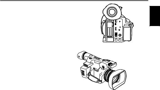
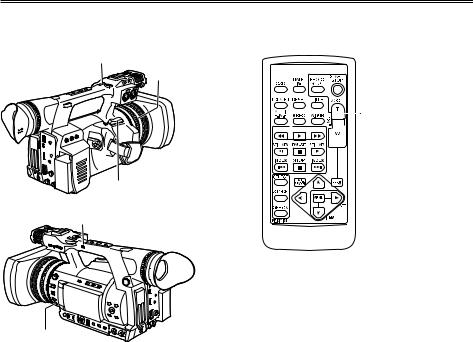
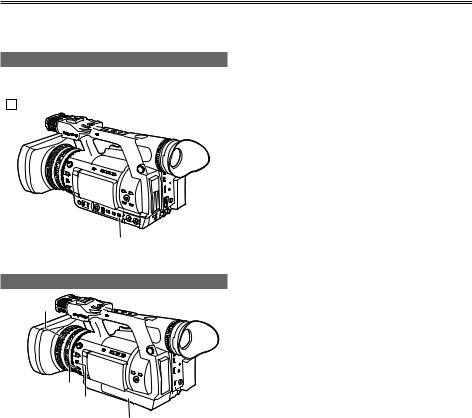
Viewfinder
This camera has two viewfinders; one is a miniature LCD in the viewfinder and the other is a retractable 3.45-type LCD.
Use the viewfinder that best suits the application and shooting conditions.
•The brightness and hue may differ between the images appearing on the viewfinder and LCD monitor and those displayed on a TV monitor. To see how the final images will appear, check them on a TV monitor.
When the LCD monitor is open, the viewfinder may not display anything. Close the LCD monitor.
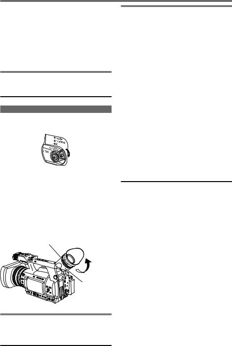
Using the viewfinder
1 Set the POWER/MODE switch to ON and check that images appear in the viewfinder.
2 Adjust the viewfinder’s angle so that the screen is positioned where it is easiest to see.
•You can move the view finder out to about 90 degrees perpendicular to the camerarecorder.
3 Adjust the Viewfinder diopter dial so that you can see the characters on the viewfinder screen clearly.
Viewfinder diopter dial
Eye piece
•The pixels of the LCD monitor are controlled to obtain high precision with 99.99 % of the effective pixels. This leaves less than 0.01 % of pixels that may not light or may remain on all the time. These phenomena are normal and will have no effect on the images you shoot.
•Screen burn-in may occur in the LCD monitor. However, this is not a defect.
•The following are all viewfinder phenomena, and are not faults. Furthermore, they have no effect on recording with this camera or on output signals.
··Primary colors (green, blue, red) may be seen in cases such as moving your line of sight within the viewfinder.
··At low temperatures, the screen may appear with a pink tint.
··When power is not supplied to the camera black lines may appear on the screen. These disappear when power is supplied.
•Image persistence may increase at low temperatures. This is not a fault.
•When the camera recorder is very cold, the LCD monitor is darker than normal immediately after switching the power ON. As the internal temperature increases it returns to normal.
Do not point the eye piece at the sun or other strong light source.
•Light concentrated by the lens could damage internal components and poses a fire hazard.
6

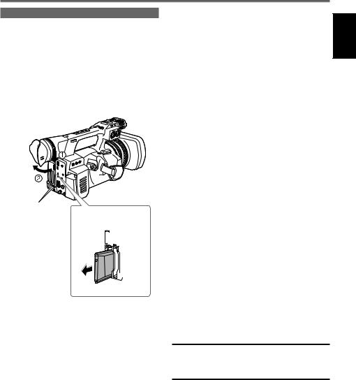
Using the LCD monitor
1 Set the POWER/MODE switch to ON.
(Page 25 of Vol. 1)
2 Open the LCD monitor.
•It can open out to 90 degrees. Do not try to open it further as this will damage the
3 Position the LCD monitor where it is easiest to see.
•The monitor can be rotated 180 degrees toward the lens and 90 degrees toward you.
•Do not apply unnecessary force to the open LCD. This can damage the camera-
• Ensure the LCD is fully closed.
Emphasizing Image Outlines
Emphasizing outlines of images in the viewfinder and on the LCD monitor makes it easier to focus. This function does not affect video output from the camera-recorder or video recorded by the camerarecorder.
Adjust EVF PEAK LEVEL and EVF PEAK FREQ in the
DISPLAY SETUP
EVF PEAK LEVEL |
0 |
|
EVF PEAK FREQ |
|
LOW |
EVF SETTING |
|
>>> |
EVF B. LIGHT |
NORMAL |
|
EVF COLOR |
ON |
|
EVF MODE |
AUTO |
|
ZEBRA1 DETECT |
100% |
|
ZEBRA2 DETECT |
85% |
|
PUSH MENU TO RETURN
Shooting
7

Viewfinder (continued)
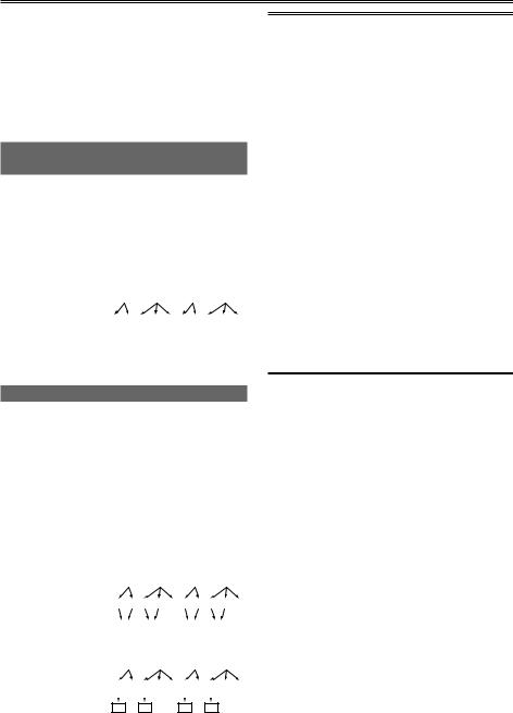
Adjusting the screen display
1 Set the POWER/MODE switch to ON.
(Page 25 of Vol. 1)
2 Press the MENU button.
•For details on menu operation, refer to “Using the setup menus” (Page 28 of Vol. 1).
•You can also use the corresponding buttons on the remote control. For details, see “Description of parts” (Remote control). (Page 19 of Vol. 1)
3 Viewfinder adjustments
Select CHANGE under EVF SETTING on the setting menu DISPLAY SETUP screen.
LCD monitor adjustments
Set CHANGE under LCD SETTING on the setting menu DISPLAY SETUP screen.
• When
DISPLAY SETUP
EVF PEAK LEVEL |
0 |
|
EVF PEAK FREQ |
LOW |
|
EVF SETTING |
|
>>> |
EVF B. LIGHT |
|
NORMAL |
EVF COLOR |
ON |
|
EVF MODE |
AUTO |
|
ZEBRA1 DETECT |
100% |
|
ZEBRA2 DETECT |
85% |
|
PUSH MENU TO RETURN
4 Push the Operation lever in the or direction to select the item.
• When
EVF SETTING
EVF BRIGHTNESS
[–] ––––––––+–––––––– [+]
EVF CONTRAST
[–] ––––––––+–––––––– [+]
PUSH MENU TO RETURN
5 Push the Operation lever in the or direction to make adjustment.
• When
EVF SETTING
EVF BRIGHTNESS
[–] ––––––––+–––––––– [+]
EVF CONTRAST
[–] ––––––––+–––––––– [+]
PUSH MENU TO RETURN
6 Press MENU three times to exit the menus.
•You can return the settings for EVF SETTING and LCD SETTING to the factory settings by selecting the item and pressing COUNTER RESET (if it is possible to change the item at that time).
•The viewfinder display can be in color or black and white. (See the setup menus, DISPLAY SETUP screen, EVF COLOR.) The resolution is the same for both of them.
Changing backlight brightness
The brightness of the LCD monitor backlight can be adjusted between five different settings.
1 Select LCD BACKLIGHT from the setup menu DISPLAY SETUP screen.
2 Select and set a value in the range of +1 to –3.
The greater the value the brighter the screen.
•This setting will remain saved even if the camera-recorder’s power is switched off.
•You can cycle through LCD BACKLIGHT values and switch backlight brightness by pressing a USER button to which “LCD B.L” has been assigned.
“Using the USER buttons” (Page 39)
8
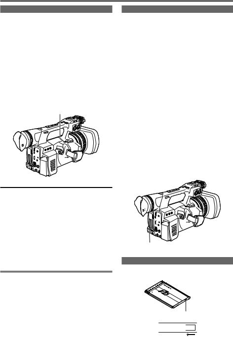
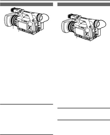
Tally lamp
The tally lamp can be illuminated during recording by setting the tally LAMP item on the OTHER FUNCTIONS screen (Page 151) to any setting other than OFF.
When the camera-recorder is in any of the following states, the tally lamp blinks.
•When the remaining battery capacity runs out (4 blinks/sec.)
•When the available recording space on the P2 card or the battery power is low (1 blink/sec.)
•When removing the P2 card during access (4 blinks/sec.)
•When there is no recording space left on the P2 card (4 blinks/sec.)
•When there is a warning for GENLOCK IN terminal signal distortion, system error, or a recording defect. (4 blinks/sec.)
Tally lamp 


 (Rear)


 Tally lamp


 (Front)
Shooting
9

Basic shooting operations
Preparing to shoot
1 Set the POWER/MODE switch to ON.
(Page 25 of Vol. 1)
2 Push the OPEN lever of the P2 card slot cover downward ( ) and slide to open ( ).
3 Insert the P2 card securely in the card slot.
4 Raise the P2 card eject button to the direction of the arrow, and close the P2 card/SD memory card slot cover.
•There are two card slots.
•Be absolutely sure to close the card slot covers to keep the dust out.
•Do not remove the P2 card while the P2 card access lamps are blinking orange. (Page 12)
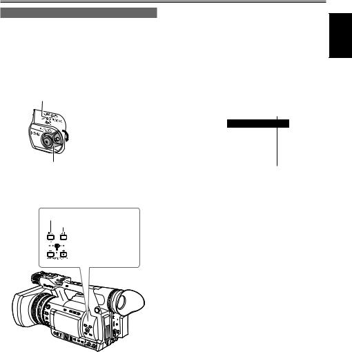
Shooting in auto mode
1 Set the POWER/MODE switch to ON.
(Page 25 of Vol. 1)
•Check that the mode lamp (CAMERA) is lighted red.
2 Switch the AUTO/MANUAL switch to AUTO to select auto mode.
•“ A ” appears on the viewfinder and LCD screens.
•The focus, gain, iris and white balance are adjusted automatically.
3 Press the START/STOP button (Red) on the POWER/MODE switch to start shooting.
•Press again to return to the camera-recorder to the shooting standby mode.
•Use the handle START/STOP button to make it easier to shoot from low angles.
•To prevent accidental operation, the handle side START/STOP button includes a hold mechanism.
START/STOP button (handle side)
4

 1
1  3
3 


POWER/MODE |
2 |
Mode lamp |
|
switch |
|||
1 (CAMERA) |
|||
Lock release button |
|||
AUTO/MANUAL |
|
||
|
|
||
|
switch |
|
|
|
AUTO MANUAL |
|
|
|
|
POWER/MODE |
|
|
|
switch |
|
|
|
Lock release button |
3
10
Under the following circumstances, even if you press the START/STOP button it may take some time until the writing to the P2 card finishes. For this reason, the operation will not
be acknowledged if you press the START/STOP button too soon.
•Stopped after only a short recording time
•Stopped immediately after the recording has moved to a second P2 card
Shooting
11
Basic shooting operations (continued)
Checking photos taken (REC CHECK)
Pressing the REC CHECK button after a recording will automatically play back the last two seconds of the most recent clip.
Holding down the REC CHECK button will allow you to play back up to 10 seconds.
Use this function to check that recording is performed normally.
•The camera-recorder returns to recording standby mode after playback.
•For clips with a playback time of 10 seconds or less, clips earlier than the current clip are not played back even if the REC CHECK button is held down after returning the clip to the start.
REC CHECK button
•Note that a backup recording performed on a backup device connected to the DVCPRO/ DV or SDI OUT connector will also record video played back using the REC CHECK function.
•In one-clip recording mode, the beginning of a clip is not used as the start position for playback after returning as far as possible with the REC CHECK function or starting playback while recording is paused. Instead, playback starts from the start point of the most recent recording operation.
P2 card access lamps
■CAMERA/PB/PC (USB HOST) mode Lights green:
Data can be saved onto the cards or loaded from them.
Blinks green (slow):
No available space on card, card is writeprotected.
Lights orange:
Slot that is the object of recording.
Blinks orange:
Data is now being accessed.
Blinks orange (fast):
A card is now being recognized.
Both lamps blink orange:
Ejection of card during access.
Off:
Cards have not been inserted or formatted. Insertion of incompatible card.
■PC (USB DEVICE) mode
Blinks orange:
Data is now being accessed.
Off:
A status other than access underway.
P2 card access lamp
Protecting against a possible erasure
Switch the write-protect switch of the P2 card to [PROTECT].
Write-protect switch
PROTECT 


12
Formatting P2 cards
1 Set the POWER/MODE switch to ON.
(Page 25 of Vol. 1)
2 Turn the POWER/MODE switch to set to PB/ THUMBNAIL mode (PB/THUMBNAIL lamp illuminates).
•Thumbnails are displayed.
Mode lamp (PB/THUMBNAIL)
POWER/MODE switch
3 Press the MENU button.
• Thumbnails menu are displayed.
MENU button
EXIT button


 Operation lever
4 On the thumbnails menu, select OPERATION and then FORMAT. (Page 91)
•A screen such as the one shown below appears. Select the number of the slot into which you inserted the P2 card to be formatted. Select EXIT to cancel the formatting.
•When you press the MENU button, the thumbnails menu display disappears.
THUMBNAIL |
|
|
|
|
|
|
|
DELETE |
|
|
|
||
|
|
|
|
|
||
OPERATION |
|
|
|
|||
PROPERTY |
|
FORMAT |
|
SLOT1 |
||
REPAIR CLIP |
|
|||||
META DATA |
|
SLOT2 |
||||
RE-CONNECTION |
||||||
HDD |
SD CARD |
|||||
COPY |
||||||
EXIT |
EXIT |
|||||
EXCH.THUMBNAIL |
||||||
|
|
|||||
|
|
|
|
|
||
|
EXIT |
|
|
|||
|
|
|
|
|
|
|
5 Select YES on the confirmation screen.
• The selected P2 card is formatted.
Shooting
13

Basic shooting operations (continued)
P2 card recording times
P2 cards available to the AG-HPX250P/EN
This camera-recorder supports the optional AJ-P2C064AG (64 GB) and AJ-P2E032XG (32 GB) P2 cards, and other 4 GB to 64 GB P2 cards (as of Sep. 2011).
•This unit cannot use AJ-P2C002SG (2 GB) cards.
•Depending on the type of P2 card used, you may need to update the camera-recorder driver.
··“Updating the firmware incorporated into the unit” (Page 158)
•For the latest information not available in the Operating Instructions, visit the support desk at the following website.
http://pro-av.panasonic.net/
P2 card recording times
(When using one 64 GB card)
System mode |
Recording |
Recording time |
|
format (codec) |
|||
|
AVC-I 100 |
Approx. 64 min. |
|
HD (1080i, 720P) |
DVCPRO HD |
||
AVC-I 50 |
Approx. 128 |
||
|
|||
|
min. |
||
|
|
||
|
|
|
|
|
DVCPRO50 |
Approx. 128 |
|
|
min. |
||
SD (480i, 576i) |
|
||
DVCPRO |
Approx. 256 |
||
|
|||
|
DV |
min. |
|
|
|
|
•The above recording time is for normal recording. Recording in native mode will extend recording time depending on system mode.
·· “Recording format list” (Page 164)
•Use of 32 GB, 16 GB and 8 GB P2 cards will provide 1/2, 1/4 and 1/8, respectively of above recording times.
•The indicated capacities include a management area so the total area available for recording is somewhat smaller.
Splitting clips recorded on P2 cards
This camera-recorder will automatically generate additional clips for a continuous recording on an 8 GB or higher capacity P2 card when the recording exceeds the durations given below. Even so, a P2 device will handle such clips as a single clip in thumbnail operations (display, delete, recover, copy, etc.). Such recordings may be handled as separate clips by nonlinear editing software or a PC.
Recording format |
Continuous |
|
(excluding Native format) |
recording time |
|
AVC-I 100 |
Approx. 5 min. |
|
DVCPRO HD |
||
|
||
AVC-I 50 |
Approx. 10 min. |
|
DVCPRO50 |
||
|
||
DVCPRO |
Approx. 20 min. |
|
DV |
||
|
14
Remove the P2 card
1 Push the OPEN lever of the P2 card slot cover downward ( ) and slide to open ( ).
2 Check that the P2 card access lamp is not blinking orange.
3 Push the P2 card eject button and press it.
4 Remove the P2 card.
P2 card access
lamp
P2 card eject button
3


4
•Do not eject the P2 card or turn the power off under the following circumstances, since doing
so may cause a malfunction in the card:
1 While the orange P2 card access lamp is
blinking after the card is inserted (and until it stops blinking).
2During recording, during the recording finish process, or while the access lamp is blinking.
•If a P2 card is ejected during formatting or while its data is being accessed, “TURN POWER OFF” appears in the viewfinder and LCD monitor, and a warning is indicated by the tally lamp. If this happens, turn the power off and back on again.
··When a card is ejected during formatting: Format the card again.
··When a card is ejected while its data is being accessed:
The clips may be thrown out of order. (Page 78) Check the clips and repair them. “Restoring clips” (Page 85)
•Immediately after pre-recording, a P2 card inserted into an empty slot will not be immediately recognized.
•During playback, a P2 card inserted into the empty slot will not be recognized and the P2 card access lamp will not light. When playback is completed, the P2 card recognition will begin.
•You can use ACCESS LED on the OTHER FUNCTIONS screen to set the P2 card access lamps so that they will always be off. In this case, either turn off the power or wait until enough time has passed after inserting the cards or stopping operation before ejecting the cards.
•When a P2 card is removed in PB/THUMBNAIL mode or PC mode (USB HOST), the screen is updated once it is closed.
However, the system returns to the thumbnail screen no matter which screen was displayed just prior to removing the card.
Furthermore, if a P2 card remains in the other slot at this time, this card will be accessed so please be careful when removing P2 cards consecutively.
Cautions in using P2 cards
Before using a P2 card, be sure to format it with a P2 device.
Shooting
15
Using SD/SDHC memory cards
You can use SD and SDHC memory cards (the term “SD memory card” is used for both hereafter) to save and load SCENE files and USER files, and to upload clip meta data. (Page 58)
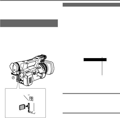
Installing and removing the SD memory card
Installation
1 Push the OPEN lever of the P2 card slot cover downward ( ) and slide to open ( ).
2 Insert the card while making sure it is oriented in the proper direction.
Access lamp
2


3 Close the P2 card/SD memory card slot cover.
Removal
1 Open the P2 card/SD memory card slot cover, and check that the access lamp is not lit.
2 Press the card further into the unit, grasp the card, and then remove.
3 Close the P2 card/SD memory card slot cover.
Formatting SD memory card
1 Set the POWER/MODE switch to ON.
(Page 25 of Vol. 1)
2 Turn the POWER/MODE switch to set to PB/ THUMBNAIL mode (PB/THUMBNAIL lamp illuminates).
3 Press the MENU button.
4 On the thumbnail menu, select OPERATION, FORMAT and then SD CARD. (Page 91)
• Select EXIT to cancel the formatting.
THUMBNAIL |
|
|
|
|
|
|
|
DELETE |
|
|
|
||
|
|
|
|
|
||
OPERATION |
|
|
|
|||
PROPERTY |
|
FORMAT |
|
SLOT1 |
||
REPAIR CLIP |
|
|||||
META DATA |
|
SLOT2 |
||||
RE-CONNECTION |
||||||
HDD |
|
|||||
SD CARD |
||||||
COPY |
||||||
EXIT |
EXIT |
|||||
EXCH.THUMBNAIL |
||||||
|
|
|||||
|
|
|
|
|
||
|
EXIT |
|
|
|||
|
|
|
|
|
|
|
5 Select YES on the confirmation screen.
•The selected SD memory card is formatted.
•You can also format from the SD CARD FORMAT option on the setting CARD FUNCTIONS screen. (Page 150)
•With SDHC cards, 32 KB of capacity will have been used.
16

Cautions in using SD memory cards
SD memory cards used with the AG-HPX250P/EN should conform to SD or SDHC standards.
Be sure to format cards using the AG-HPX250P/ EN.
SD memory cards with the following capacity can be used for the AG-HPX250P/EN.
SDXC memory cards are not available for this product.
SD (from 8 MB to 2 GB) SDHC (from 4 GB to 32 GB)
For the latest information not available in the Operating Instructions, visit the P2 Support Desk at the following Web sites. http://pro-av.panasonic.net/
•SD memory cards must not be used or stored in an environment where they may be
··Exposed to high temperatures/humidities;
··Exposed to water droplets; or
··Electrically charged.
•Be sure always close the cover when using an SD memory card.
•See also “Checkpoints for using memory cards” (Page 162).
Shooting
17
Using the zoom function
This camera-recorder has a 22 x optical zoom function.
Zoom with the zoom lever or the zoom ring.
Zoom lever (handle side)
Zoom ring
Zoom lever (grip side)
HANDLE ZOOM switch
ZOOM switch
Zoom lever
Set the ZOOM switch to SERVO so that you can use the motor-driven zoom.
T : Zoom in W : Zoom out
Gently press the zoom button on the grip to zoom slowly, firmly press to zoom faster.
Zoom lever (handle side)
You can change the zoom speed on the handle zoom button by selecting one of three speeds with the HANDLE ZOOM switch.
Set the HANDLE ZOOM switch speeds by going to the setup menus, SW MODE screen HANDLE ZOOM. (Page 138)
Zoom ring
Set the ZOOM switch to MANUAL so that you can use the zoom ring.
•You cannot use the zoom ring if the ZOOM switch is set to SERVO. Trying to use it could damage the camera-recorder.
On the remote control
Press ZOOM/VOL to zoom with the motor drive.
• Zoom speed is fixed at medium.


 ZOOM/VOL button
18

Digital zoom function
Assign the D.ZOOM function to USER MAIN or any of the USER 1 – 4 buttons to enable use of the digital zoom. (Page 39)
Each press of the USER button to which D.ZOOM is assigned switches the zoom ratio in the following order: OFF (x1) → x2 → x5 → x10 → OFF (x1).
•The viewfinder and the LCD monitor indicate the zoom ratio when a setting other than OFF (x1) is selected.
•“Using the USER buttons” (Page 39)
Please take note of the following points regarding use of the digital zoom function.
•Digital zoom is not available when the DRS (dynamic range stretcher) function (Page 133) or the SCAN REVERSE function (Page 136) is running.
•The FBC (flash band compensation) function (Page 38) is not available when the digital zoom function is running. The FBC function becomes available again when digital zoom is switched back to OFF.
•Operating the DRS function or SCAN REVERSE function when the digital zoom function is running switches the digital zoom function off.
Shooting
19
Shooting in progressive mode
In 1080i and 480i (576i) mode, this unit can perform progressive shooting when CAMERA MODE of the setting menu is set to 24P, 24PA, or 30P (25P).
When performing progressive shooting, the recording format can be set to native (which uses the camera’s shooting frame rate as is) or standard (which pulls the frame rate down to 59.94 (50)).
Standard recording (pull-down recording)
24P records with 2:3 pulldown and 30P (25P) records with 2:2 pulldown, and both record as 59.94i (50i).
The camera-recorder can also handle video shot in the 24PA mode (2:3:3:2 advanced pulldown). Note that AVC-Intra does not support pulldown recording.
Camera-recorder |
|
|
|
|
|
|
|
|
|
|
|
|
|
|
A |
|
|
B |
|
|
C |
|
|
D |
|
||
capture |
|
|
|
|
|
|
|
|
|
|
|
|
|
(1080/24P over 60i) |
Ao |
Ae |
Bo |
Be |
Bo |
Ce |
Co |
De |
Do |
De |
|
||
2:3 pull-down |
|
|
|
|
|
|
|
|
|
|
|
|
|
recording |
|
|
|
|
|
|
|
|
|
|
|
|
|
|
|
|
|
|
|
|
|
|
|
|
|
|
|
Native recording
This format extracts and records only effective frames when 1080i mode is used with 24PN or 30PN (25PN) AVC-Intra mode.
Furthermore, native recording format for both DVCPRO HD and AVC-Intra is supported with 720P, enabling recording of 2 – 2.5x longer than pull down recording.
Also in native recording, the output of camerarecorder video and playback video is a 59.94 (50) frame rate.
Camera-recorder |
|
|
|
|
|
|
|
|
|
|
|
|
|
|
|
|
|
|
|
|
|
A |
|
B |
|
|
|
C |
|
|
D |
||||||
capture (1080/24PN) |
|
|
|
|
|
|
|
|
|
|
|
|
|
|
|
|
|
|
2:3 pull-down |
Ao |
Ae |
Bo |
Be |
Bo |
Ce |
Co |
De |
Do |
De |
||||||||
Recording |
|
|
|
|
|
|
|
|
|
|
|
|
|
|
||||
|
|
A |
|
|
B |
|
|
|
|
C |
|
D |
|
|||||
|
|
|
|
|
|
|
|
|
|
|
|
|
|
|
|
|
|
|
Camera-recorder |
|
|
|
|
|
|
|
|
|
|
|
|
|
|||||
|
|
|
A |
|
B |
|
|
|
C |
|
|
D |
||||||
capture (720/24PN) |
|
|
|
|
|
|
|
|
|
|
|
|
|
|
|
|
|
|
2:3 pull-down |
A |
|
A |
B |
B |
B |
C |
|
C |
D |
D |
D |
||||||
Recording |
|
|
|
|
|
|
|
|
|
|
|
|
|
|
|
|
||
A |
|
|
B |
|
|
|
|
C |
|
|
D |
|||||||
|
Active frame |
|
|
|
|
|
|
|||||||||||
|
|
|
|
|
|
|
|
|
|
|
|
|
|
|
|
|
|
|
•In 24P/24PA, 24PN (native recording) and in 30PN/25PN (native recording) at 720P, the camera starts recording in 5-frame, 4-frame and 2-frame segments, respectively. For this reason, to continue recording clips in a system mode using a different recording segmentation may break the continuity of the time code.
•The camera uses internal memory for recording, when recording starts as soon as a P2 card is inserted or the camera is powered up. In this situation, recording cannot be stopped until P2 card recognition ends.
To check P2 card status, press the DISP/ MODE CHK button and check the row for SLOT 1 and 2 displayed in the viewfinder or LCD monitor.
•An editing system that supports 24PA (2:3:3:2 advanced pulldown) will enable editing with less quality loss than 24P (2:3 pulldown).
•Record at standard 24P if a 24PA compatible editing system will not be used.
20
Recording with Variable Frame Rate (VFR)
In 1080i and 720P mode, this unit can shoot using frame skipping (under cranking) and high speed recording (over cranking). You can select native (PN) recording mode and standard (OVER) recording.
Native VFR recording
1 In 1080i or 720P mode, set REC FORMAT on the setting menu SYSTEM SETUP screen to AVC-I 100/24PN (or 30PN, 25PN).
2 In the SCENE FILE screen, set the menu option VFR to ON and the menu option FRAME RATE to suit shooting purposes.
You can also change the frame rate using the SHTR/F.RATE dial.
• “Setting FRAME RATE mode” (Page 51)
3 Press the START/STOP button.
This starts recording in the VFR mode (native VFR).
This mode can be combined with the AVC-I 100, AVC-I 50, 30PN (25PN), and 24PN recording formats.
You can also select DVCPRO HD with 720P.
•“Setting FRAME RATE mode” (Page 51)
•“SYSTEM SETUP screen” (Page 135)
Note the following about native VFR recording.
•Pre-recording, loop recording, interval recording, one-shot recording, and one-clip recording are not available.
•1394 output is not available during recording and recording standby.
•Changing Scene Dial position during recording does not change VFR on and off position.
•Sound cannot be recorded. *1
At this time, no audio is output and
“ A. REC ” is displayed over the audio level meter. “VFR ON, NO AUDIO RECORDING” is also displayed when recording starts.
•The time code is locked to Rec Run. *1
•Thumbnail screens are created 1 frame later than video recorded on a P2 card, but this is not a malfunction.
•The screen may be distorted when changing the FRAME RATE setting.
•Gain is fixed to 0 dB when set to 4 frames or less.
Furthermore, AGC, auto iris, auto focus, and ATW do not function and must be operated manually.
•Red, blue, or green points may appear on the screen when the frame rate is low. This is not a fault.
*1 In 24PN/30PN (25PN) recording modes, when the frame rate is 24 and 30 (25) frames per second, respectively, audio can also be recorded. The time code can be set to Free Run (F-RUN).
Shooting
21

Recording with Variable Frame Rate (VFR) (continued)
Standard VFR recording (pulldown recording)
1 In 1080i or 720P mode, set REC FORMAT on the setting menu SYSTEM SETUP screen to AVC-I 100/60i (60P) (or 50i, 50P).
2 In the SCENE FILE screen, set the menu option VFR to ON and the menu option FRAME RATE to suit shooting purposes.
You can also change the frame rate using the SHTR/F.RATE dial.
• “Setting FRAME RATE mode” (Page 51)
3 Press the START/STOP button.
This starts recording in the VFR mode (pulldown recording).
This mode can be combined with the AVC-I 100/60P (50P), AVC-I 50/60P (50P) 30PN, and DVCPROHD/60P (50P) recording formats in 720P system mode, and AVC-I 100/60i (50i), AVC-I 50/60i (50i), DVCPROHD/60i (50i) in 1080i system mode.
•“Setting FRAME RATE mode” (Page 51)
•“SYSTEM SETUP screen” (Page 135)
•With AVC-Intra or DVCPRO HD in 1080i, clips are recorded as 60i, 60P (50i, 50P) with pull down information not recorded.
•Audio playback is disabled when a frame rate converter is used to extract active frames for over and under-cranking.
Note the following about standard VFR recording.
•Pre-recording, loop recording, interval recording, one-shot recording, and one-clip recording are not available.
•1394 output is available during recording and recording standby, but not in AVC Intra mode.
•Changing Scene Dial position during recording does not change VFR on and off position.
•Sound is recorded.
•The screen may be distorted when changing the FRAME RATE setting.
•Gain is fixed to 0 dB when set to 4 frames or less.
Furthermore, AGC, auto iris and ATW do not function and must be operated manually.
•Red, blue, or green points may appear on the screen when the frame rate is low. This is not a fault.
22

Using progressive mode and VFR recording function
Standard speed for film production
Screen production normally requires a 24 fps (24 frames per second) frame rate (normal speed) for screening a film. Making the settings described below will provide film-quality playback. The 720P progressive mode and cine-like gamma will make video look like it was shot with a film camera-recorder.
Standard settings for film production
|
SYSTEM MODE settings |
|
Recording frame rate |
||
SYSTEM MODE |
Other settings |
||||
|
|||||
|
|
|
AVC-I 100/24PN |
|
|
720-59.94P |
REC FORMAT |
|
(AVC-I 50/24PN) |
|
|
|
|
(DVCPROHD/24PN) |
|
||
|
|
|
|
||
|
VFR |
|
OFF |
|
|
|
|
|
AVC-I 100/24PN |
24 frames |
|
|
REC FORMAT |
|
(AVC-I 50/24PN) |
|
|
1080-59.94i |
|
|
(DVCPROHD/60i) |
|
|
|
CAMERA MODE*1 |
|
24P, 24PA |
|
|
|
VFR |
|
OFF |
|
|
*1: Only when the menu option REC FORMAT is set to DVCPROHD/60i in the SYSTEM SETUP screen.
Shooting
23

Recording with Variable Frame Rate (VFR) (continued)
Shooting at standard speed for producing commercials and TV programs
When producing videos for display on a television screen such as HDTV/SDTV broadcast, a frame rate of 30 fps (30 frames per second), 25 fps (25 frames per second) for 50 Hz, is standard (x1). The settings below allow you to obtain the kind of playback used for broadcast programs. This permits film-like video recording of commercials and music clips that also provide a frame rate suitable for broadcasting.
Standard settings for producing commercials and dramas
|
SYETEM MODE settings |
|
Recording frame rate |
||
SYSTEM MODE |
Other settings |
||||
|
|||||
|
|
|
AVC-I 100/30PN |
|
|
720-59.94P |
REC FORMAT |
|
(AVC-I 50/30PN) |
|
|
|
|
(DVCPROHD/30PN) |
|
||
|
|
|
|
||
|
VFR |
|
OFF |
|
|
|
|
|
AVC-I 100/30PN |
30 frames |
|
|
REC FORMAT |
|
(AVC-I 50/30PN) |
|
|
1080-59.94i |
|
|
(DVCPROHD/60i) |
|
|
|
CAMERA MODE*1 |
|
30P |
|
|
|
VFR |
|
OFF |
|
|
|
|
|
AVC-I 100/25PN |
|
|
720-50P |
REC FORMAT |
|
(AVC-I 50/25PN) |
|
|
|
|
(DVCPROHD/25PN) |
|
||
|
|
|
|
||
|
VFR |
|
OFF |
|
|
|
|
|
AVC-I 100/25PN |
25 frames |
|
|
REC FORMAT |
|
(AVC-I 50/25PN) |
|
|
1080-50i |
|
|
(DVCPROHD/50i) |
|
|
|
CAMERA MODE*1 |
|
25P |
|
|
|
VFR |
|
OFF |
|
|
*1 Only when the menu option REC FORMAT is set to DVCPROHD/60i (50i) in the SYSTEM SETUP screen.
24

Undercranking effects
This effect produces the quick motion often used for showing clouds drifting across the sky, crowds of people swarming past a solitary standing individual, a kung fu demonstration and other performances. For example, selecting a VFR recording frame rate of 12 fps when shooting at a 24P recording format yields a fast-motion effect of approx. 2x normal speed.
Standard setup for undercranking effects
|
SYSTEM MODE settings |
|
Recording frame rate |
||
SYSTEM MODE |
Other settings |
||||
|
|||||
|
REC FORMAT |
|
AVC-I 100/24PN |
|
|
|
|
(AVC-I 50/24PN) |
|
||
1080-59.94i |
|
|
1 to 22 frames |
||
VFR |
|
ON |
|||
|
|
|
|||
|
FRAME RATE |
|
Set to 23 frames or less |
|
|
|
REC FORMAT |
|
AVC-I 100/25PN |
|
|
|
|
(AVC-I 50/25PN) |
|
||
1080-50i |
|
|
1 to 24 frames |
||
VFR |
|
ON |
|||
|
|
|
|||
|
FRAME RATE |
|
Set to 24 frames or less |
|
|
|
|
|
AVC-I 100/24PN |
|
|
|
REC FORMAT |
|
(AVC-I 50/24PN) |
|
|
720-59.94P |
|
|
(DVCPROHD/24PN) |
1 to 22 frames |
|
|
VFR |
|
ON |
|
|
|
FRAME RATE |
|
Set to 22 frames or less |
|
|
|
|
|
AVC-I 100/25PN |
|
|
|
REC FORMAT |
|
(AVC-I 50/25PN) |
|
|
720-50P |
|
|
(DVCPROHD/25PN) |
1 to 24 frames |
|
|
VFR |
|
ON |
|
|
|
FRAME RATE |
|
Set to 24 frames or less |
|
|
•With the menu option REC FORMAT set to DVCPROHD/60P (50P), you can use a nonlinear editing system to generate quick motion effects from the resulting footage.
Shooting
25

Recording with Variable Frame Rate (VFR) (continued)
Overcranking effects
Overcranking produces slow-motion playback, which is frequently used in climax scenes, or for dramatic effects like car chases and action scenes. For example, selecting a recording frame rate of 60 fps when shooting a 24P recording format yields a slow-motion effect that is 2.5 times normal speed. Shooting 720P progressive video will produce smooth and highquality slow-motion.
Furthermore, with 1080i, a slow motion effect of 1.25 can be gained if you set the recording frame rate to 30 fps when recording was performed using 24P, a recording format for specifying the playback frame rate.
Standard setup for overcranking effects
|
SYSTEM MODE setup |
|
Recording frame rate |
||
SYSTEM MODE |
Other settings |
||||
|
|||||
|
REC FORMAT |
|
AVC-I 100/24PN |
|
|
|
|
(AVC-I 50/24PN) |
|
||
1080-59.94i |
|
|
25 to 30 frames |
||
VFR |
|
ON |
|||
|
|
|
|||
|
FRAME RATE |
|
Set to 25 frames or more |
|
|
|
|
|
AVC-I 100/24PN |
|
|
|
REC FORMAT |
|
(AVC-I 50/24PN) |
|
|
720-59.94P |
|
|
(DVCPROHD/24PN) |
25 to 60 frames |
|
|
VFR |
|
ON |
|
|
|
FRAME RATE |
|
Set to 25 frames or more |
|
|
|
|
|
AVC-I 100/25PN |
|
|
|
REC FORMAT |
|
(AVC-I 50/25PN) |
|
|
720-50P |
|
|
(DVCPROHD/25PN) |
26 to 50 frames |
|
|
VFR |
|
ON |
|
|
|
FRAME RATE |
|
Set to 26 frames or more |
|
|
•With the menu option REC FORMAT set to DVCPROHD/60P (50P), you can use a nonlinear editing system to generate slow motion effects from the resulting footage.
•A slow motion effect cannot be gained if SYSTEM MODE is set to 1080-50i and REC FORMAT is set to AVC-I***/25PN.
26

Flow effect shooting
This way of shooting provides a flow effect and may, for instance, be used to shoot a subject on a far side of a road with a stream of fast-moving cars as the flow, in such a way that the stationary subject comes into focus though the cars.
1 Set SYSTEM MODE on the setting menu SYSTEM SETUP screen to 1080-59.94i (50i), REC FORMAT to AVC-I 100 (50)/60i (50i) or DVCPRO HD/60i (50i), and VFR to ON.
Set FRAME RATE to a low value suitable for the shooting purpose.
Setting can be performed in the same way for 720P.
2 Press the START/STOP button.
This starts recording in the VFR mode.
During flow effect shooting - general notes
•Please take note of the following points when selecting AVC-Intra recording.
··When 1080i is selected, the image signal and HD SDI output signal recorded are 60i (50i) and all frames are effective frames.
··With both 1080i and 720P, pull down information is not attached to recorded clips.
When you wish to use this information, select DVCPRO HD mode with 720P.
•Audio recording will be recorded onto P2 card at all frame rates.
•Fixed shutter and synchro scan are valid.
Shooting
27
Shooting in manual mode
Set the unit to manual mode when manually adjusting the focus, iris, gain and white balance.
Switching to manual mode
Slide the AUTO/MANUAL switch to MANUAL to switch to the manual mode.
( A on the viewfinder and LCD go out.)
AUTO/MANUAL switch
Manual focusing
Focus ring
PUSH AUTO 


 button FOCUS


switch
AUTO/MANUAL switch
1 Use the AUTO/MANUAL switch to switch to manual mode.
2 Use the FOCUS switch to choose how to control focusing.
A (AUTO): (Auto focus mode)
Adjusts focus automatically.
M (MANUAL): (Manual focus mode)
Turn the focus ring by hand.
∞:
The camera-recorder first focuses on infinity, then it switches to manual focus.
The FOCUS switch automatically moves back to M (MANUAL) after you move it to ∞.
Temporarily switching to auto focus
Even if you have switched FOCUS to M (MANUAL) the camera-recorder will focus automatically while you press down PUSH AUTO.
Switching to manual focus assist mode
To change from the manual focus mode to the manual focus assist mode, set MF ASSIST to ON on the setting menu SW MODE screen.
•You can make coarse adjustments to the focus in manual focus assist mode by turning the focus ring about half the amount you would turn it in manual focus mode.
•Fine adjustment is made automatically after you operated the focus ring.
•If the focus differs considerably form the manually set focus, the focus may not be set correctly.
•Automatic adjustment is not performed until you operate the focus ring for the next time.
•Auto focus may not work properly if there is flickering. Select a shutter speed suited to the ambient light. (Page 49)
•If the auto focus mode is set with any format except 60i (50i) and 60P (50P), controlling the focus will take slightly longer than in the normal focus mode.
•If you have set ON for the AF item on the setting menu AUTO SW screen, auto focusing will occur regardless of the position of the FOCUS switch when the auto mode has been established. (Page 140)
•When the display is set to macro shooting, the screen display for “AF”, “MF”, and “MA” is reversed black and white characters.
28

Using focus assist function
Pressing the FOCUS ASSIST button magnifies the image at the center to facilitate focusing.
Set the menu option FOCUS BAR to ON in the DISPLAY SETUP screen to display the focus bar.
FOCUS BAR: (DISPLAY SETUP menu)
The length of the bar indicates whether the image is in focus.
The focus bar extends to the far right when the image is in focus.
Shooting
Out of focus
FOCUS ASSIST button
This function magnifies only the image at the center of the LCD monitor and viewfinder.
It is not superimposed on signals output via the VIDEO OUT, SDI OUT and HDMI OUT connectors.
EXPANDED: (FOCUS ASSIST button)
Trebles the size of the center of the image. The status indication and the zebra pattern disappears and EXPANDED appears at the top of the screen.
EXPANDED
•The EXPANDED display is available only during recording and does not work in external input mode.
In VIDEO OUT, SDI OUT, and HDMI OUT, the center of the image is not magnified and status indications do not appear.
The bar extends to the right when the image is in focus.
29
Shooting in manual mode (continued)
Iris adjustments
IRIS ring
IRIS button
1 If the camera-recorder is in auto mode, use the AUTO/MANUAL switch to switch to manual mode. (Page 28)
2 Press the IRIS button to switch how to adjust the aperture of lens.
AUTO IRIS:
Adjust the iris automatically.
MANUAL IRIS:
Adjust the iris manually.
3 Turn the IRIS ring to adjust the aperture of lens when in the manual iris mode.
In the auto iris mode, the lens iris can be corrected using this ring.
If you have set ON under A.IRIS on the setting menu AUTO SW screen, auto iris will be forcibly selected when auto mode has been established. (Page 140)
•This unit’s iris F number when it is open is F1.6 at full WIDE and F3.2 at full TELEPHOTO. The iris display in the viewfinder or on the LCD when the iris is open is OPEN at full WIDE and F3.2 or OPEN at full TELEPHOTO.
•You can display the brightness level for the center part of the screen by pressing a USER button (Page 39) to which Y GET has been assigned.
Adjusting the gain
When the display is dark, increase the gain to
GAIN switch
1 If the camera-recorder is in auto mode, use the AUTO/MANUAL switch to switch to manual mode. (Page 28)
2 Switch the gain with the GAIN switch.
L:Set here under normal conditions. (The default value is 0 dB.)
M:Increase the gain of the image amplifier. (The default value is 6 dB.)
H:Increase the gain of the image amplifier. (The default value is 12 dB.)
You can change each L, M and H gain values using the LOW GAIN, MID GAIN and HIGH GAIN items on the setting menu SW MODE screen. (Page 138) In auto mode, auto gain is available regardless of the GAIN switch setting when a setting other than OFF is selected under AGC on the setting menu AUTO SW screen. (Page 140)
In variable frame rate (VFR) mode, gain is fixed to 0 dB when the frame rate is set to 4 frames or less.
30
 Loading...