


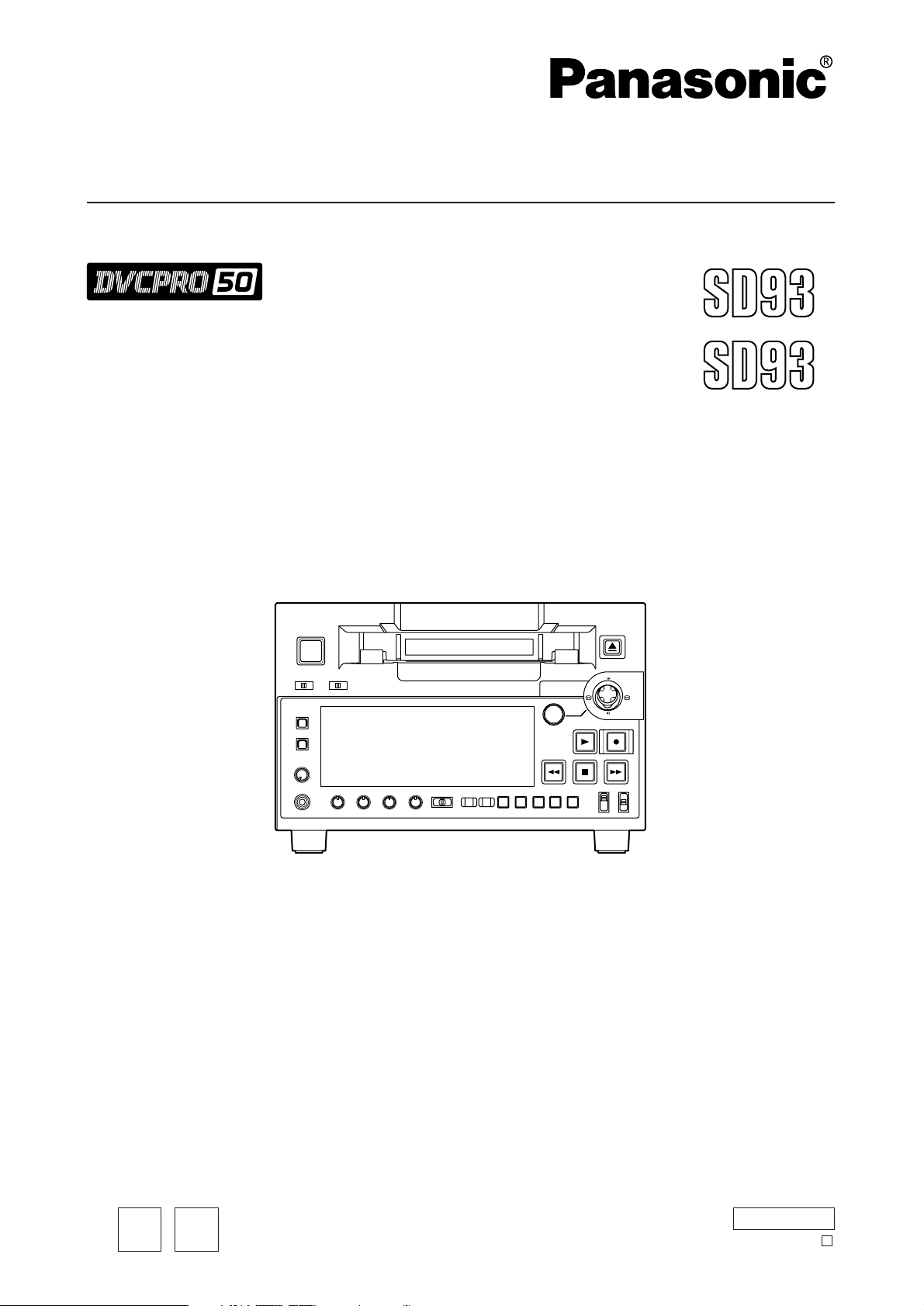
AJ-SD93
Before operating this product, please read the instructions carefully and save this manual for future use.
Digital Video Cassette Recorder
Operating Instructions
AJ-
P
ENGLISH
AJ-
E
Model No.
Printed in Japan
VQT0L54-1
EP
S0704A1074 -M
D
– 2 –
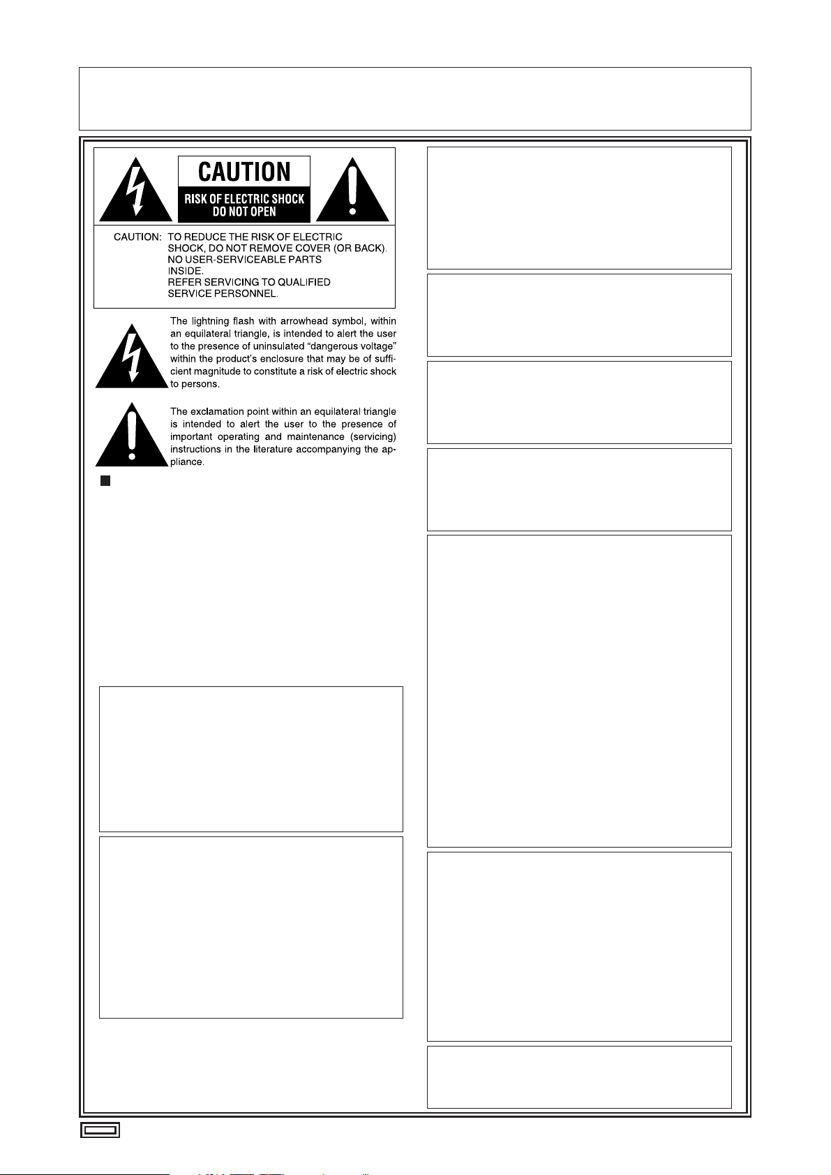
IMPORTANT
“Unauthorized recording of copyrighted television programmes, video tapes and other materials
may infringe the right of copyright owners and be contrary to copyright laws.”
For AJ-SD93P
THIS APPARATUS MUST BE GROUNDED
To ensure safe operation the three-pin plug must be
inserted only into a standard three-pin power outlet
which is effectively grounded through normal
household wiring.
Extension cords used with the equipment must be
threecore and be correctly wired to provide connection
to the ground. Incorrectly wired extension cords can be
extremely hazardous.
The fact that the equipment operates satisfactorily
does not imply that it is grounded, and the installation
is not necessarily safe. For your safety, if in any doubt
about the effective grounding of the equipment or
power outlet, please consult a qualified electrician.
WARNING:
TO REDUCE THE RISK OF FIRE OR SHOCK
HAZARD, DO NOT EXPOSE THIS EQUIPMENT
TO RAIN OR MOISTURE.
TO REDUCE THE RISK OF FIRE OR SHOCK
HAZARD, KEEP THIS EQUIPMENT AWAY FROM
ALL LIQUIDS-USE AND STORE ONLY IN
LOCATIONS WHICH ARE NOT EXPOSED TO
THE RISK OF DRIPPING OR SPLASHING
LIQUIDS, AND DO NOT PLACE ANY LIQUID
CONTAINERS ON TOP OF THE EQUIPMENT.
CAUTION:
Do not install or place this deck in a bookcase,
built-in cabinet or any other confined space in
order to maintain adequate ventilation. Ensure
that curtains and any other materials do not
obstruct the ventilation to prevent risk of
electric shock or fire hazard due to overheating.
CAUTION:
TO REDUCE THE RISK OF FIRE OR SHOCK
HAZARD AND ANNOYING INTERFERENCE,
USE THE RECOMMENDED ACCESSORIES
ONLY.
CAUTION:
TO REDUCE THE RISK OF FIRE OR SHOCK
HAZARD, REFER MOUNTING OF THE
OPTIONAL INTERFACE BOARD TO QUALIFIED
SERVICE PERSONNEL.
CAUTION:
TO REDUCE THE RISK OF FIRE OR SHOCK
HAZARD, REFER CHANGE OF SWITCH
SETTING INSIDE THE DECK TO QUALIFIED
SERVICE PERSONNEL.
CAUTION:
This apparatus can be operated at a voltage in the
range of 100 – 240 V AC.
Voltage other than 120 V is not intended for U.S.A.
and Canada.
CAUTION:
Operation at a voltage other than 120 V AC may
require the use of a different AC plug. Please
contact either a local or foreign Panasonic
authorized service center for assistance in
selecting an alternate AC plug.
CAUTION:
Even when the Power Switch is in the OFF
position, a small current flows the filter circuit.
FCC Note:
This equipment has been tested and found to
comply with the limits for a class A digital device,
pursuant to Part 15 of the FCC Rules. These limits
are designed to provide reasonable protection
against harmful interference when the equipment is
operated in a commercial environment. This
equipment generates, uses, and can radiate radio
frequency energy and, if not installed and used in
accordance with the instruction manual, may cause
harmful interference to radio communications.
Operation of this equipment in a residential area is
likely to cause harmful interference in which case
the user will be required to correct the interference
at his own expense.
Warning: To assure continued FCC emission limit
compliance, the user must use only shielded interface
cables when connecting to external units. Also any
unauthorized changes or modifications to this
equipment could void the user’s authority to operate it.
indicates safety information.
CAUTION:
TO COMPLETELY DISCONNECT THIS
APPARATUS FROM THE AC MAINS,
DISCONNECT THE POWER SUPPLY CORD
PLUG FROM THE AC RECEPTACLE.
THE AC OUTLET (MAIN SOCKET) SHALL BE
INSTALLED NEAR THE EQUIPMENT AND
SHALL BE EASILY ACCESSIBLE.
– 3 –
indicates safety information.
For AJ-SD93E
FOR U.K. ONLY
This appliance is supplied with a moulded three pin
mains plug for your safety and convenience.
A 13 amp fuse is fitted in this plug.
Should the fuse need to be replaced please ensure that
the replacement fuse has a rating of 13 amps and that it
is approved by ASTA or BSI to BS1362.
Check for the ASTA mark or the BSI mark on the
body of the fuse.
If the plug contains a removable fuse cover you must
ensure that it is refitted when the fuse is replaced.
If you lose the fuse cover the plug must not be used
until a replacement cover is obtained.
A replacement fuse cover can be purchased from your
local Panasonic Dealer.
IF THE FITTED MOULDED PLUG IS UNSUITABLE
FOR THE SOCKET OUTLET IN YOUR HOME THEN
THE FUSE SHOULD BE REMOVED AND THE PLUG
CUT OFF AND DISPOSED OF SAFELY. THERE IS A
DANGER OF SEVERE ELECTRICAL SHOCK IF THE
CUT OFF PLUG IS INSERTED INTO ANY 13 AMP
SOCKET.
If a new plug is to be fitted please observe the wiring
code as shown below.
If in any doubt please consult a qualified electrician.
WARNING: THIS APPLIANCE MUST BE EARTHED.
IMPORTANT: The wires in this mains lead are coloured
in accordance with the following code:
Green-and-Yellow: Earth
Blue: Neutral
Brown: Live
As the colours of the wires in the mains lead of this
appliance may not correspond with the coloured
markings identifying the terminals in your plug, proceed
as follows:
The wire which is coloured GREEN-AND-YELLOW
must be connected to the terminal in the plug which is
marked with the letter E or by the Earth symbol or
coloured GREEN or GREEN-AND-YELLOW.
The wire which is coloured BLUE must be connected
to the terminal in the plug which is marked with the
letter N or coloured BLACK.
The wire which is coloured BROWN must be
connected to the terminal in the plug which is marked
with the letter L or coloured RED.
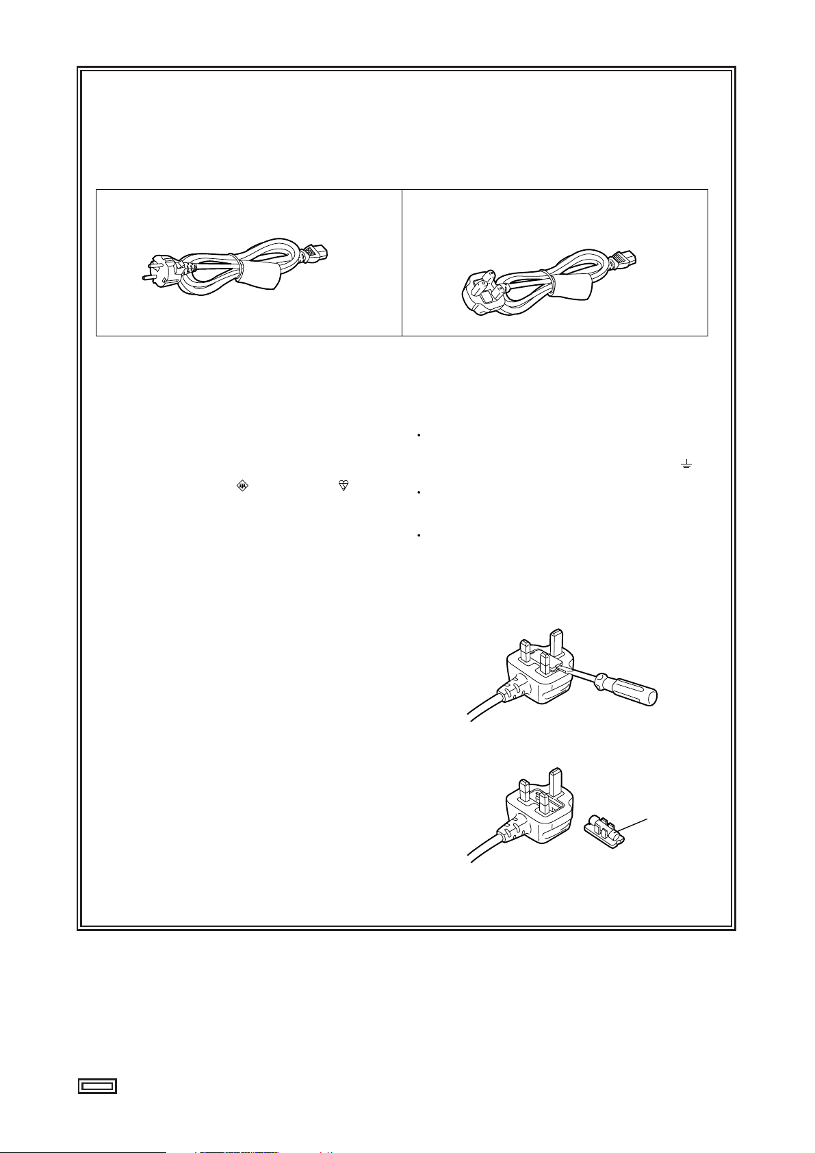
FOR YOUR SAFETY PLEASE READ THE FOLLOWING TEXT CAREFULLY.
This product is equipped with 2 types of AC mains cable. One is for continental Europe, etc. and the other one is only
for U.K.
Appropriate mains cable must be used in each local area, since the other type of mains cable is not suitable.
FOR CONTINENTAL EUROPE, ETC.
Not to be used in the U.K.
FOR U.K. ONLY
If the plug supplied is not suitable for your socket
outlet, it should be cut off and appropriate one fitted.
Caution for AC Mains Lead
How to replace the fuse
1.Open the fuse compartment with a screwdriver.
2.Replace the fuse.
Fuse
– 4 –
indicates safety information.
For AJ-SD93E
IMPORTANT
“Unauthorized recording of copyrighted television
programmes, video tapes and other materials may
infringe the right of copyright owners and be
contrary to copyright laws.”
Operating precaution
Operation near any appliance which generates strong
magnetic fields may give rise to noise in the
video and audio signals. If this should be the case,
deal with the situation by, for instance, moving the
source of the magnetic fields away from the unit before
operation.
THIS APPARATUS MUST BE EARTHED
To ensure safe operation the three-pin plug must be
inserted only into a standard three-pin power point
which is effectively earthed through the normal house-
hold wiring.
Extension cords used with the equipment must be
three-core and be correctly wired to provide
connection to earth. Wrongly wired extension cords
are a major cause of fatalities.
The fact that the equipment operates satisfactorily
does not imply that the power point is earthed and that
the installation is completely safe. For your safety, if in
any doubt about the effective earthing of the power
point, consult a qualified electrician.
DO NOT REMOVE PANEL COVER BY
UNSCREWING.
To reduce the risk of electric shock, do not remove
cover. No user serviceable parts inside.
Refer servicing to qualified service personnel.
WARNING:
TO REDUCE THE RISK OF FIRE OR SHOCK
HAZARD, KEEP THIS EQUIPMENT AWAY FROM
ALL LIQUIDS-USE AND STORE ONLY IN
LOCATIONS WHICH ARE NOT EXPOSED TO
THE RISK OF DRIPPING OR SPLASHING
LIQUIDS, AND DO NOT PLACE ANY LIQUID
CONTAINERS ON TOP OF THE EQUIPMENT.
CAUTION:
TO REDUCE THE RISK OF FIRE OR SHOCK
HAZARD, REFER MOUNTING OF THE
OPTIONAL INTERFACE BOARD TO
AUTHORIZED SERVICE PERSONNEL.
CAUTION:
TO REDUCE THE RISK OF FIRE OR SHOCK
HAZARD, REFER CHANGE OF SWITCH
SETTING INSIDE THE DECK TO QUALIFIED
SERVICE PERSONNEL.
CAUTION:
Do not install or place this deck in a bookcase,
built-in cabinet or any other confined space in
order to maintain adequate ventilation. Ensure
that curtains and any other materials do not
obstruct the ventilation to prevent risk of
electric shock or fire hazard due to overheating.
CAUTION:
Even when the Power Switch is in the OFF
position, a small current flows the filter circuit.
CAUTION:
TO REDUCE THE RISK OF FIRE OR SHOCK
HAZARD AND ANNOYING INTERFERENCE,
USE THE RECOMMENDED ACCESSORIES
ONLY.
CAUTION:
TO COMPLETELY DISCONNECT THIS
APPARATUS FROM THE AC MAINS,
DISCONNECT THE POWER SUPPLY CORD
PLUG FROM THE AC RECEPTACLE.
THE AC OUTLET (MAIN SOCKET) SHALL BE
INSTALLED NEAR THE EQUIPMENT AND
SHALL BE EASILY ACCESSIBLE.

– 5 –
Contents
Introduction ......................................................6
Included accessories ......................................6
Optional boards ...............................................6
Features ...........................................................7
Parts and their functions .................................8
• Front Panel ........................................................8
• Display Panel...................................................11
• Rear Panel.......................................................12
Tapes ...............................................................13
IEEE 1394 digital interface.............................14
Joystick ...........................................................15
PF (Programmable Function) ........................15
• Registering the items in the PF buttons...........15
• Performing operations using the PF buttons....15
Repeat playback .............................................16
Setup (initial settings)....................................17
Setup menus...................................................18
• SYSTEM menu ................................................20
• USER menus ...................................................21
<BASIC> .....................................................21
<OPERATION>...........................................23
<INTERFACE> ...........................................24
<TAPE PROTECT> ....................................25
<TIME CODE>............................................26
<VIDEO>.....................................................28
<AUDIO> ....................................................30
<V BLANK>.................................................32
<DIF> ..........................................................33
<MENU> .....................................................34
Time code/user bit..........................................35
Superimpose screen ......................................36
Video head cleaning.......................................37
Condensation .................................................37
Maintenance....................................................37
Error messages ..............................................38
Specifications .................................................43

– 6 –
Introduction
The model AJ-SD93 multi-purpose digital VTR uses small,
1/4-inch wide cassette tapes to record and play back
images with a high picture quality at a video recording rate
of 50 Mbps while it can also record and play back
DVCPRO (25 Mbps) format tapes as well as play back
consumer-use DV/DVCAM tapes.
It comes with the following features.
•This high-picture-quality VTR incorporates digital
compression technology to dramatically reduce the
deterioration of the picture quality and sound quality
resulting from dubbing.
•It is equipped with an IEEE 1394 interface as a
standard feature and, in compliance with the IEEE
1394 standard, it can digitally transmit video and
audio signals as well as time code signals to a digital
VTR, etc.
•It has a compact and lightweight design so that it can
readily be carried around or easily installed in a rack.
3-pin power cord x 1
Included accessories
•Analog interface board:
AJ-YA93P
•SDI interface board:
AJ-YA94G
Use only the optional boards listed above.
Optional boards

– 7 –
Features
Compact and lightweight
This unit is a DVCPRO50 digital VTR which uses 1/4-
inch wide cassette tapes. Its compact and lightweight
design makes it ideal as a feeder for non-linear editing
or as a viewer installed on a desk-top, for instance.
Up to 92 minutes of recording
M cassettes (max. 33 minutes: using the AJ-5P33MP)
and L cassettes (max. 92 minutes: using the AJ-
5P92LP) can be used with this unit. Tape width is a
compact 1/4-inch.
Superior picture quality
Superior picture quality is achieved through 4:2:2
component signal recording at 2 times the recording
rate of the DVCPRO format.
4-channel, high-sound-quality digital audio
The unit can record and play back 4-channel PCM
audio. (However, it does not support cue recording or
playback.)
IEEE 1394 digital input/output
The IEEE 1394 digital interface, which is provided as a
standard feature, enables DVCPRO50 or DVCPRO/DV
compressed digital video and audio signals to be input
and output with no accompanying deterioration of the
picture quality.
Compatibility with DVCPRO (25 Mbps) format
This unit can record, play back and edit material in the
DVCPRO (25 Mbps) format.
Compatibility with general consumer video
equipment
DV cassette tapes containing material shot with a
consumer digital camera or the like can be played
back on this unit. A cassette adapter (AJ-CS455P) is
necessary when a mini DV cassette tape is to be used.
Digital slow motion
Panasonic's original digital slow-motion technology
makes it possible to obtain clear pictures even during
slow playback at speeds ranging from -0.43x to +0.43x.
(DVCPRO, DVCPRO50 only)
Joystick
The unit comes with a joystick (stick controller). It is
used to control variable-speed playback during
searches, etc.
In addition, the settings for the on-screen menus and
time code generator can also be accomplished easily
using the joystick.
PF (Programmable Function) buttons
The unit comes with three PF buttons. Any three
frequently used setup menus can be selected, and by
operating these buttons on the front panel, it is possible
to change the menu settings.
Recording and playback of UMID information
Recording and playback of UMID (Unique Material
Identifier) information complies with the SMPTE 330M
standard.
UMID information can be checked on the DIAG menu.
Time code
The unit incorporates a TCG (time code
generator)/TCR (time code reader). In addition to the
internal time code, use of the analog interface board
(option: AJ-YA93P) enables the external time code
input or input signal VITC to be recorded on the unit as
the time code.
Multi-functional interfaces
• Serial digital input/output
Use of the SDI interface board (option: AJ-YA94G)
enables interfacing of the serial digital component
signals.
• Analog video/audio input/output
Use of the analog interface board (option: AJ-YA93P)
enables the following signals :
- Composite video input/output
- Component video input/output
- Reference video input (BNC, input x1; loop-through
x1)
- Analog audio input/output
Input: XLR, 4 channels; output: XLR, 4 channels
- Time code input/output (BNC connectors, 1 each
for input, output)
- 9-pin control input (RS-422)
Menu-based setup
The setup settings, which are conducted prior to
operating the unit, are performed while viewing the
setup menus on the unit’s display or a TV monitor.
UMID information cannot be played back
correctly by VTRs that do not support the
recording and playback of UMID information.
In addition, even if a VTR that does not support
the recording and playback of UMID information
is connected to this unit and recording
performed, UMID information will not be
recorded correctly.
– 8 –
Parts and their functions
Front panel
Digital Video Cassette Recorder AJ-
SUPER
ON
OFF
TCG
REGEN
PRESET
EXT
INT
COUNTER
PF PF
1
PF
2
PF
3DIAG
MENU
PUSH
SHTL/SLOW
TC
PRESET
METER
FULL/FINE
MONITOR SEL
RESET
REC PB
UNITY
INPUT SELECT
VIDEO AUDIO
CH 1 CH 2 CH 3 CH 4
HEADPHONES
SEARCH
EJECT
POWER
REC INHIBITCONTROL
ON
ON
OFF
OFF
LOCAL
REMOTE
RECPLAY
FFREW STOP
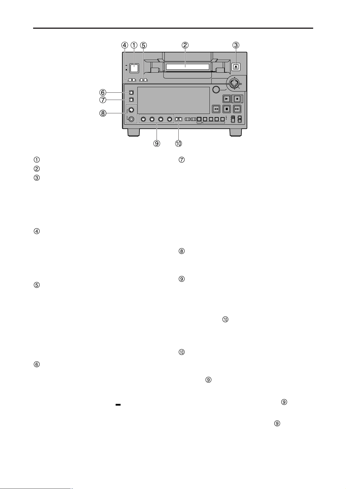
POWER switch
Cassette insertion slot
EJECT button
When this button is pressed, the tape is unloaded and
the cassette is ejected automatically a few seconds
later.
When CTL display has been selected for the counter
display, the display is reset.
EJECT button operation can be enabled or disabled
with setup menu No. 115 (EJECT SW INH).
CONTROL switch
This is selected to control the unit from an external
source using the REMOTE connector.
REMOTE: Set to this position to control the unit using
the 9-pin REMOTE connector and IEEE
1394 AV/C commands.
LOCAL : Set to this position to control the unit using
the controls on the unit's operation panel.
REC INHIBIT switch
This switch is used to enable or disable recording on
the cassette tape.
ON:
Recording on the cassette tape is disabled
(inhibited).
In this state, the REC INH lamp lights on the display
panel.
OFF:
Recording on the cassette tape is enabled so long
as the accidental erasure prevention mechanism on
the cassette tape is set to enable recording.
METER (FULL/FINE) selector button
This button is used to select the scale display for the
audio level meter.
FULL mode : The standard scale (– ∞ to 0 dB) is
selected.
FINE mode : The scale in 0.5 dB increments is
selected. The position indicates
the standard level of –20 dB (–18 dB).
(See page 11)
MONITOR SEL button
This button is used to select the audio signals which
are to be output to the AUDIO MON L and R
connectors.
Each time the button is pressed, the audio signals to
be output to the AUDIO MON L or R connector are
changed in the following sequence.
Which signal is currently selected is displayed by the
lighting of the L or R lamp on the level meter display.
Headphone jack and volume control
When stereo headphones are connected to the
headphone jack, the sound can be monitored using
the headphones during recording or playback.
Audio level control knobs
These knobs are used to adjust the recording and
playback level of the PCM audio signals (CH1, CH2,
CH3 and CH4).
Whether the recording level or playback level is to be
adjusted is selected using the audio level control
selector switch .
Note:
The level of the IEEE 1394 digital input/output audio
signals cannot be adjusted.
Audio level control selector switch
UNITY: At this position, the audio signals are recorded
or played back at a fixed level regardless of
the position of the audio level control knobs
.
REC : At this position, the audio signals are
recorded at the level which has been adjusted
by the audio level control knobs .
PB : At this position, the audio signals are played
back at the level which has been adjusted by
the audio level control knobs .
Note:
It is not possible to set this switch so that both the
recording level and playback level can be adjusted.
When REC is selected, UNITY (fixed level) is set for
the playback level; when PB is selected, UNITY is set
for the recording level.
L : [CH1] [CH3] [CH1] [CH2] [CH3] [CH4]
R : [CH2] [CH4] [CH1] [CH2] [CH3] [CH4]
[CH1+CH2] [CH3+CH4]
[CH1+CH2] [CH3+CH4]
→→→→→
→→
– 9 –
Parts and their functions (continued)
Digital Video Cassette Recorder AJ-
SUPER
ON
OFF
TCG
REGEN
PRESET
EXT
INT
COUNTER
PF PF
1
PF
2
PF
3DIAG
MENU
PUSH
SHTL/SLOW
TC
PRESET
METER
FULL/FINE
MONITOR SEL
RESET
REC PB
UNITY
INPUT SELECT
VIDEO AUDIO
CH 1 CH 2 CH 3 CH 4
HEADPHONES
SEARCH
EJECT
POWER
REC INHIBITCONTROL
ON
ON
OFF
OFF
LOCAL
REMOTE
RECPLAY
FFREW STOP
INPUT SELECT buttons
These buttons are used to switch the video and audio
input signals. They can also be used to switch the
input signals to the internal reference signal selected
as the setup menu item No.600 (INT SG) setting.
VIDEO:
Each time the VIDEO button is pressed, the input
video signal selection is switched in the order of [Y PB
PR] →[CMPST] → [SDI] → [1394] → [SG].
• When SG has been selected, the signal is
switched to the internal reference signal selected
as the setup menu item No.600 (INT SG) setting.
AUDIO:
Each time the AUDIO button is pressed, the input
audio signal selection is switched in the order of
[ANALOG] → [SDI] → [1394] → [SG].
Notes:
• It is possible to inhibit the input switch operations
(video and audio) of the INPUT SELECT buttons
using setup menu item No.112 (V IN SEL INH) and
item No.113 (A IN SEL INH).
• The Y PB PR and CMPST settings for the VIDEO
button as well as the ANALOG setting for the
AUDIO button cannot be selected unless the
optional board (AJ-YA93P) has been installed.
• The SDI setting for the VIDEO and AUDIO buttons
cannot be selected unless the optional board (AJ-
YA94G) has been installed.
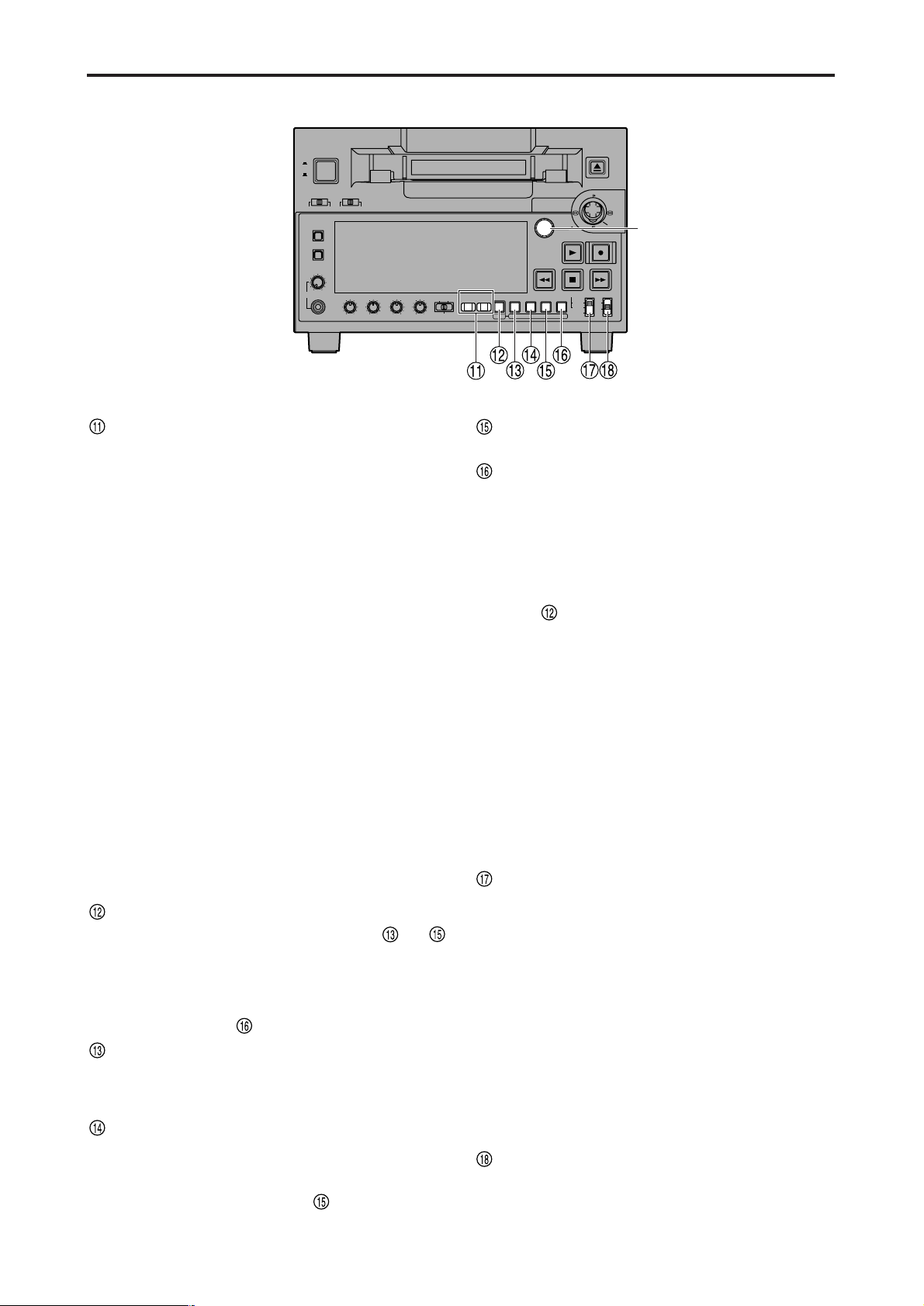
PF button
When this button is pressed, buttons to
function as the PF1, PF2 and PF3 buttons,
respectively. When it is pressed again before another
button is pressed, these modes are canceled.
When this button is pressed together with the
MENU/DIAG button , the DIAG screen is displayed.
COUNTER/PF1 button
Each time this button is pressed, the counter display
on the display panel changes by one step in the
following sequence: CTL → TC → UB.
RESET/PF2 button
When this button is pressed in the CTL mode, the
counter display is reset to [00:00:00:00].
When it is pressed in the TC/UB mode while holding
down the TC PRESET button , the generator is
reset.
TC PRESET/PF3 button
This button is used to set the TC or UB values.
MENU/DIAG button
When this button is pressed, the setup menus are
displayed on the TV monitor (but only when the VIDEO
MON connector is used), and the setup menu
numbers are displayed on the unit’s display panel.
When it is pressed again, the setup menu settings are
exited, and the original status is restored.
When the button is pressed while holding down the PF
button , the VTR information is displayed. When it
is pressed again, the original display is restored. The
VTR information consists of the WARNING, HOURS
METER, UMID and DIF STATUS 1, 2 information.
The SEARCH button is used to switch the displays
between these kinds of information.
Descriptions of the warnings are displayed on the
WARNING screen. The deck’s serial number, power-
on time, drum rotation time, tape travel time, number
of loading times, number of power on/off times, etc.
are displayed on the HOURS METER screen. The
UMID (Unique Material Identifier) information is
displayed on the UMID INFO screen. The IEEE 1394
digital interface information is displayed on the DIF
STATUS 1, 2 screen.
TCG switch
REGEN:
The internal time code generator is synchronized with
the time code which the time code reader has read
from the tape.
The signal that is to be used for regeneration is
selected using setup menu No. 503 (TCG REGEN).
PRESET:
The time code generator can be preset (see page 35)
on the operation panel or by remote control.
EXT:
The external time code which is input from the time
code input connector or video signal VITC, or
IEEE1394 digital input signal is used. Which of the two
is to be set is selected using setup menu No. 505
(EXT TC SEL).
SUPER switch
ON : The time code and other superimposed
information are output to the VIDEO MON
connector.
OFF : No superimposed information is output.
Front panel
SEARCH
button
– 10 –
Parts and their functions (continued)
Digital Video Cassette Recorder AJ-
SUPER
ON
OFF
TCG
REGEN
PRESET
EXT
INT
COUNTER
PF PF
1
PF
2
PF
3DIAG
MENU
PUSH
SHTL/SLOW
TC
PRESET
METER
FULL/FINE
MONITOR SEL
RESET
REC PB
UNITY
INPUT SELECT
VIDEO AUDIO
CH 1 CH 2 CH 3 CH 4
HEADPHONES
SEARCH
EJECT
POWER
REC INHIBITCONTROL
ON
ON
OFF
OFF
LOCAL
REMOTE
RECPLAY
FFREW STOP
Front panel
Joystick
This is used for shuttle, slow and other variable-speed
playback. It is also used for the menu settings, etc.
The stick can be moved upward, downward, to the left
or to the right, and it can also be pressed to initiate
operations.
SEARCH button
When this button is pressed, the search mode is
established.
PLAY button
When this button is pressed, playback starts.
When this button and the REC button are pressed
together, recording starts.
REC button
When this button is pressed together with the PLAY
button, recording starts.
When it is pressed during playback, a search, fast
forwarding or rewinding, the E-E mode pictures and
audio signals can be monitored while it is held down.
When it is pressed in the stop mode, the E-E mode
pictures and audio signals can be monitored. (When it
is pressed during playback, the servo will be
disrupted.) When the STOP button is pressed, the
original pictures and sound are restored.
REW button
When this button is pressed, the tape is rewound. The
rewinding speed can be selected using setup menu
No.102 (FF. REW MAX).
FF button
When this button is pressed, the tape is fast
forwarded.
The fast forwarding speed can be selected using setup
menu No.102 (FF. REW MAX).
STOP button
When this button is pressed, the tape stops traveling,
and when TAPE has been selected for the setup menu
item No.122 (STOP EE SEL) setting, the still images
can be monitored.
Even in the stop mode, the drum continues to rotate,
and the tape remains in close contact with the drum.
When the stop mode continues beyond a specific time
period, the unit is automatically set to the standby OFF
mode or STEP FWD mode in order to protect the tape.
(This is set using setup menu item No.400 to 403.)
Immediately after a cassette has been loaded in the
unit, the stop mode is established.
– 11 –
Parts and their functions (continued)
Display panel
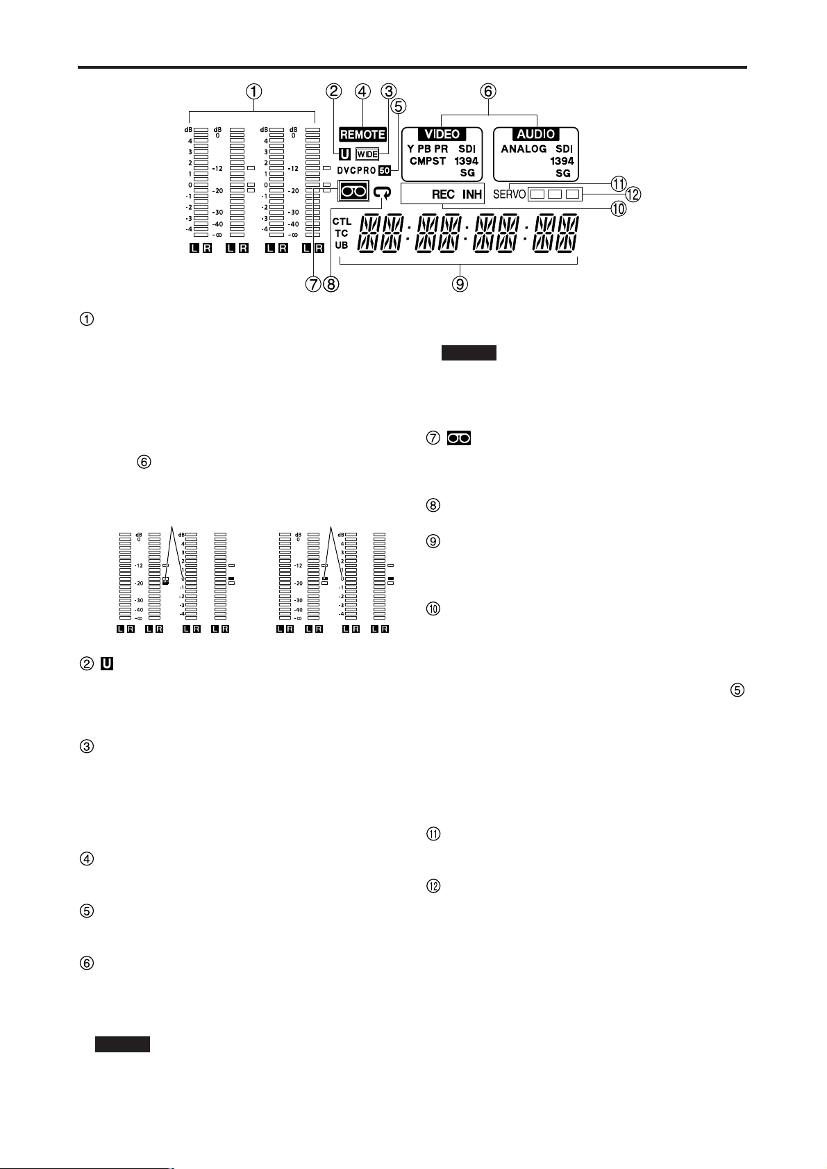
Level meter
This displays the levels of the PCM audio signals for
CH1, CH2, CH3 and CH4.
During recording and when the E-E mode is selected,
it shows the levels of the input audio signals; during
playback, it shows the levels of the output audio
signals.
The audio level display is switched between the FULL
mode and FINE mode using the METER selector
button . (See page 8)
lamp
This lamp lights when UMID information is present on
the input signal in E-E mode.
This lamp lights during tape playback when UMID
information has been recorded on the tape.
WIDE lamp
This lamp lights when 16:9 wide-screen information is
being recorded on a tape.
Recording of wide-screen information can be selected
on setup menu No. 645 (WIDE SELECT).
This lights lamps during tape playback when wide-
screen information has been recorded on the tape.
REMOTE lamp
This lamp lights when the CONTROL switch has been
set to the REMOTE position.
Format displays
The recording format and the format of the tape
inserted in the unit are displayed here.
INPUT SELECT display area
The characters corresponding to the selected input
signals light up in this area. With the exception of
analog audio signals, flashing appears in this area if
the selected input signals are not available.
Y PB PR : Analog component video signals (option)
CMPST : Analog composite video signals (option)
SDI : Serial digital video signals (option)
VIDEO
1394 : IEEE1394 digital signals
SG : Internal reference signal
ANALOG : Analog audio signals (option)
SDI : Serial digital audio signals (option)
1394 : IEEE1394 digital signals
SG : Internal reference signal
lamp
This lamp lights when a cassette tape is inserted into
the VTR.
In the standby OFF mode, this lamp is flashing.
Repeat lamp
This lights when the repeat play mode has been set.
Counter display
The tape counter, time code, etc. are displayed here.
The type of value displayed is indicated by CTL, TC or
UB.
REC/REC INH lamps
REC:
This lights in the recording mode.
REC INH:
This lights in the recording inhibit mode which is
established either when the REC INHIBIT switch
has been set to ON or the cassette has been set to
the accidental erasure prevention status. Recording
is not possible while this lamp is lighted.
Whether the lamp is to light or flash when the
accidental erasure prevention tab on the cassette
tape has been set to the recording inhibit position
can be selected using setup menu item No.114
(REC INH LAMP).
SERVO lamp
This lights when both the drum servo and capstan
servo are locked.
Channel condition lamps
These lamps light to indicate the error rate status.
(green → white → red)
Green : This lights when the error rates for the video
and audio playback signals are both at
acceptable levels.
White : This lights when the error rate for the video or
audio playback level has increased.
The playback picture and sound remain
unaffected even while this lamp is lighted.
Red : This lights when the error rate for the video or
audio playback level has increased to the
extent that correction or interpolation was
performed.
AUDIO
FULL mode
FINE mode
Reference level
(–20 dB)
FULL mode
FINE mode
Reference level
(–18 dB)
For AJ-SD93P
For AJ-SD93E
– 12 –
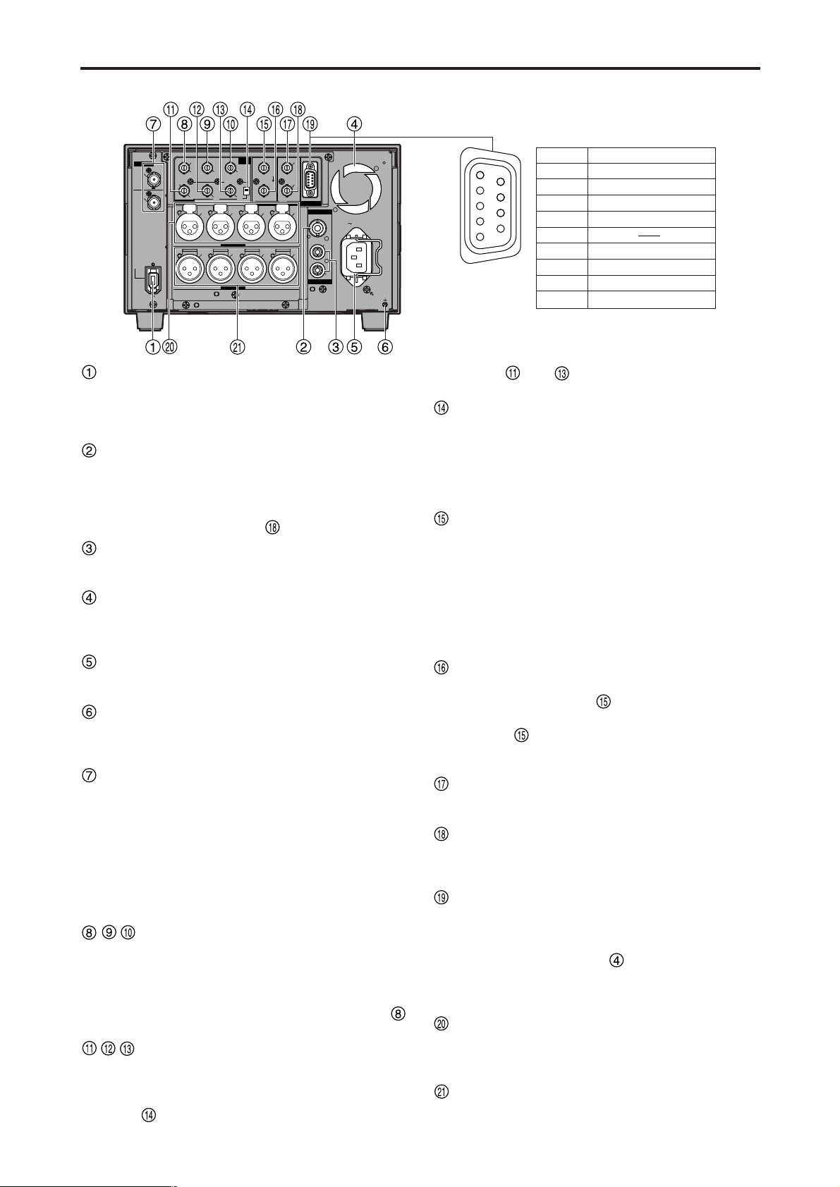
Parts and their functions (continued)
DVCPRO
/DV
AUDIO MON
AUDIO OUT
VIDEO MON
(SUPER)
750
AUTO
IN
OUT
VIDEO
Y
VIDEO1
SDI
IN
SDI
OUT
VIDEO2
L
CH
1
CH
2
CH
3
CH
4
CH
1
CH
2
CH
3
CH
4
Y
R
AC IN
AUDIO IN
P
B
P
R
P
B
P
R
VIDEO OUT
DIGITAL
VIDEO
IN
REF VIDEO IN TIME CODE REMOTE
SIGNAL
GND
9
1
6
5
Pin No.
1 Frame Ground
Signal
2 Transmit A
3 Receive B
4 Receive Common
5
6 Transmit Common
7 Transmit B
8 Receive A
9 Frame Ground
Rear panel
IEEE 1394 digital input/output connector
This enables signals to be input and output using the
IEEE 1394 digital interface. Use a 6-pin type of
connector.
Bus power is not supported.
VIDEO MON connector
Analog composite video signals are output from this
connector.
Video signals with information superimposed on them
can be output. To set the superimposing to ON or
OFF, use the SUPER switch on the front panel.
AUDIO MON (L, R) connectors
The playback signal from the PCM audio signals (CH1,
CH2, CH3, CH4) are output from these connectors.
Fan
This fan is used to cool down the VTR.
If, for any reason, the fan stops, “E-10” will appear on
the counter display.
AC IN socket
Connect one end of the power cord supplied to this
socket and the other end to the power outlet.
SIGNAL GND terminal
This is connected to the signal ground terminal on the
component connected to this VTR in order to minimize
noise. It is not a safety ground.
SERIAL DIGITAL COMPONENT AUDIO
VIDEO IN/OUT connectors (option: AJ-
YA94G)
Digital component audio/video signals complying with
the SMPTE 259M-C standard are input to and output
from these connectors.
Note:
The digital audio signals to be input must be
synchronized with the video input signals. Otherwise,
noise will be generated in the audio output signals.
ANALOG VIDEO IN connectors
(option: AJ-YA93P)
Analog component video signals are supplied to these
connectors when the INPUT SELECT button on the
front panel is set to Y PB PR. Analog composite video
signals are supplied using the VIDEO/Y connector
when the button is set to CMPST.
ANALOG VIDEO OUT connectors
(option: AJ-YA93P)
Analog component video signals are output from these
connectors when the ANALOG VIDEO OUT selector
switch has been set to the Y PB PR side (bottom
position). Analog composite video signals are output
from the and connectors when the switch has
been set to the VIDEO1/VIDEO2 side (top position).
ANALOG VIDEO OUT selector switch
(option: AJ-YA93P)
Set this switch to the Y PB PR side (bottom position)
when the ANALOG VIDEO OUT connectors are used
to output component video signals; set it to the
VIDEO1/VIDEO2 side (top position) when they are
used to output composite video signals.
REF VIDEO IN connector (option: AJ-YA93P)
This is the input connector for the reference video
signal. Input a signal with color burst.
Note:
Since the video or audio output signal may be
disrupted if the reference video signal is not input,
it is recommended that this connector be used by the
system which supplies the reference video signals.
Use a signal where SCH does not fluctuate for the
reference video signal.
REF VIDEO OUT connector (option: AJ-YA93P)
This is the loop-through output connector of the REF
VIDEO IN connector . When a cable is not
connected to this connector, the REF VIDEO IN
connector is automatically terminated by the 75 Ω
resistance. When a cable is connected, the 75 Ω
termination is released.
TIME CODE IN connector (option: AJ-YA93P)
This connector is used for recording the external time
code onto the tape.
TIME CODE OUT connector (option: AJ-YA93P)
The playback time code is output from this connector
during playback. During recording, the time code
generated by the internal time code generator is output.
Remote control connector (option: AJ-YA93P)
This enables the unit to be connected to the external
remote controller for operation from an external source.
Notes:
• Set the CONTROL switch to REMOTE.
• The specifications are based on the RS-422A
interface, and editing-related functions do not work.
In this case, use it as a player.
ANALOG AUDIO IN connectors (option: AJ-
YA93P)
The analog audio signals are input from these
connectors.
ANALOG AUDIO OUT connectors (option: AJ-
YA93P)
The analog audio signals are output from these
connectors.
– 13 –
Digital Video Cassette Recorder AJ-
SUPER
ON
OFF
TCG
REGEN
PRESET
EXT
INT
COUNTER
PF PF
1
PF
2
PF
3DIAG
MENU
PUSH
SHTL/SLOW
TC
PRESET
METER
FULL/FINE
MONITOR SEL
RESET
REC PB
UNITY
INPUT SELECT
VIDEO AUDIO
CH 1 CH 2 CH 3 CH 4
HEADPHONES
SEARCH
EJECT
POWER
REC INHIBITCONTROL
ON
ON
OFF
OFF
LOCAL
REMOTE
RECPLAY
FFREW STOP
Tapes
Consumer-use DV and DVCAM cassettes
(Standard DV and DVCAM cassettes, mini DV
and DVCAM cassettes)
• Use a cassette adapter (AJ-CS455P) when a mini DV
or DVCAM cassette is to be used.
Note that inserting a mini DV or DVCAM cassette
without the use of a cassette adapter will cause
malfunctioning.
Also note that long-duration mini DV cassettes (80
minutes in the standard mode and 120 minutes in the
LP mode) cannot be used.
• It is not possible to play back tapes which have been
recorded in the LP mode.
• When editing material recorded on a consumer-use
DV or DVCAM cassette, first record the material on a
DVCPRO tape or other tape used by VTRs for
broadcast applications.
• The maximum transport speed of a mini DV or
DVCAM cassette tape is 32x.
• The images may be subject to disturbance during the
slow motion playback of consumer-use DV and
DVCAM cassette tapes.
• From the perspective of protecting consumer-use DV
and DVCAM cassette tapes, minimize the number of
times the tapes are cued up at the same locations as
much as possible.
• When consumer-use DV and DVCAM cassette tapes
are used, the maximum time for STILL TIMER is set
to 10 seconds.
It is recommended that tapes bearing the Panasonic
brand be used as the consumer-use DV tapes.
Align the center of the cassette with the center
of the insertion slot, and press it in gently.
The cassette tape will load automatically.
M cassettes
Tapes capable of up to 33 minutes of recording or
playback
(AJ-5P23MP, AJ-5P33MP)
L cassettes
Tapes capable of up to 92 minutes of recording or
playback
(AJ-5P63LP, AJ-5P92LP)
• Use AJ-5P92LP tapes which have been recorded using
the DVCPRO (25M) format in a VTR that supports 184
minutes of DVCPRO (25M) format recording and
playback.
M cassette size
L cassette size
– 14 –
IEEE 1394 digital interface
Precautions for use
• Connect the interface with another device on a 1:1
basis.
• If the E-92 warning (1394 INITIAL ERROR) is
displayed, either re-connect the connecting cable or
turn the VTR’s power off and back on.
• The AV signals may be disrupted when the power of
the connected devices is turned on or off and when
the interface cable is connected or disconnected.
• When the input signals are switched or the mode is
transferred, it may take a few seconds for the system
to stabilize. Proceed with the recording operation only
after the system has stabilized.
• The following situation applies when recording is to
be performed by selecting the IEEE 1394 digital
interface input, and it applies with the signals which
are output by the IEEE 1394 digital interface.
- The audio level control knobs on the front panel do
not work.
- The settings in the 800 series of setup menu items
concerning the vertical blanking period are ignored.
- When playback signals other than regular 1x
speed playback signals have been input, no
guarantees are made for the pictures and sound
which will be recorded or for the EE-type pictures
and sound.
• The following situation applies when the video input
selection has been set as the IEEE 1394 digital
interface.
- The SDI signals, the analog video output signals
and time code output signals become irregular in
the E-E mode. Do not use these signals for
recording purposes. (The teletext signals and other
signals superimposed onto the video output signals
also become irregular.)
• During SLOW/STILL playback, unprocessed video
and audio signals are output as the IEEE 1394 digital
interface output. When these video and audio signals
are monitored using another device, they may differ
from the video and audio signals played back by this
unit.
Be absolutely sure not to defeat the
following safeguards when connecting the
IEEE 1394 cable.
(1) Ensure that the unit and all devices to be
connected are grounded (or connected to a
common ground).
If the equipment cannot be grounded, first turn off the
power of all the connected devices, and then
disconnect and re-connect the IEEE 1394 cable.
(2) When connecting the unit to a device
equipped with a 4-pin connector, connect the
unit’s connector (6-pin type) first.
(3) When making a connection to a PC equipped
with a 6-pin connector, connect the 1394
cable so that it mates properly with the 1394
connector. Bear in mind that if the plug is
inserted the wrong way round, the unit may
be damaged as a result.
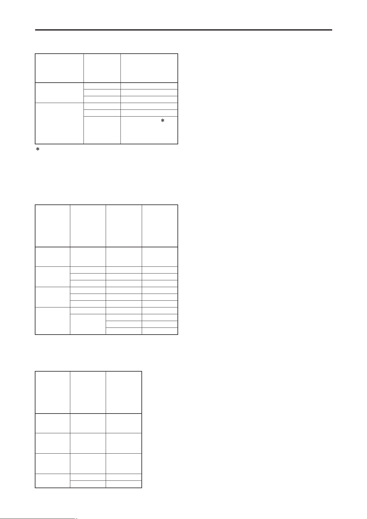
Setup menu
No. 012
(SYS FORMAT)
settings
50M
25M
Input data
DVCPRO50
DVCPRO
DV
DVCPRO50
DVCPRO
DV
Recording format
data
DVCPRO50
Recording not possible
Recording not possible
Recording not possible
DVCPRO
For AJ-SD93P 1:
DVCPRO
For AJ-SD93E:
Recording not possible
Setup menu
No. 881
(DIF TYPE)
setting
During
DVCPRO50
tape playback
During
DVCPRO
tape playback
During
DV/DVCAM
tape playback
During
EJECT or E-E
Setup menu
No. 012
(SYS
FORMAT)
setting
–
–
–
–
–
–
–
50 M
25 M
Mode
DVCPRO50
DVCPRO
DVCPRO
DV
DV
DVCPRO
DV
DVCPRO50
DVCPRO
DVCPRO
DV
Output data
format
–
AUTO
DVCPRO
DV
AUTO
DVCPRO
DV
–
AUTO
DVCPRO
DV
During
DVCPRO50
tape playback
During
DVCPRO
tape playback
During
DV/DVCAM
tape playback
During
EJECT or E-E
Setup menu
No. 012
(SYS
FORMAT)
setting
–
–
–
50 M
25 M
Mode
DVCPRO50
DVCPRO
DV
DVCPRO50
DVCPRO
Output data
format
The recording format for IEEE 1394 digital input data is
determined based on the table below.
1 If the audio of the input data is 32 kHz/4CH, CH1/CH2
and CH3/CH4 can be selected in setup menu No. 889
(DIF AUD IN).
For AJ-SD93P:
The format for IEEE 1394 digital output data is determined
based on the setup menu No. 881 (DIF TYPE) setting and
playback tape (mode).
For AJ-SD93E:
The format for IEEE 1394 digital output data is determined
based on the playback tape (mode).
 Loading...