


Operating Instructions Vol.2
Digital AV Mixer
Model No.
Model No.
AG-HMX100P AG-HMX100E
Volume 2
Note that Operating Instructions Vol. 2 describes advanced operations of the digital AV mixer.
For instructions on basic operations of the digital AV mixer, refer to Operating Instructions Vol. 1 (printed document) supplied with this unit.
Before operating this product, please read the instructions carefully and save this manual for future use.
ENGLISH
M0810RI1100 -PS |
VQT2U23A-1 |

 Contents
|
Volume 1 |
|
Requests on Use |
|
|
Before Calling for Service |
||
Overview |
Specifications |
|
Features/AV Mixer Functions/Accessories/Components |
||
and Functions |
Index |
|
Basic Operation
System Configuration Examples/Power-On/Initial Setup/
Switching or Combining of Video
Volume 2
Chapter 1 Applying Effects to Video and Sound
Setting of Video Switching and Combining Effects........ |
3 |
Setting the Transition (Wipe) Pattern [TRANSITION]........ |
3 |
Setting the Basic Pattern Key [BASIC PATTERN KEY]/ |
|
Pattern Key [PATTERN KEY]......................................... |
5 |
Setting the Chroma Key [CHROMA KEY]......................... |
6 |
Setting the Luminance Key [LUMINANCE KEY] / |
|
External Key [EXT KEY]................................................. |
7 |
Setting the Title Key [TITLE KEY]..................................... |
8 |
Setting Key Learn [KEY LEARN]...................................... |
9 |
Setting the Downstream Key (DSK) ............................... |
11 |
Setting the Fade [FADE]................................................. |
12 |
Adjusting Input Video ..................................................... |
13 |
Adjusting Colors of Video [COLOR EFFECTS]............... |
13 |
Applying Effects to Video [VIDEO EFFECTS]................. |
13 |
Setting Audio Effects....................................................... |
17 |
[AUDIO EFFECTS] Menu................................................ |
17 |
Chapter 2 Registering Settings and |
|
Effects |
|
File operation [FILE]........................................................ |
19 |
Event Memory Operation................................................. |
20 |
Registering the Current Settings and Created Effects |
|
as Events..................................................................... |
20 |
Calling Events................................................................. |
20 |
Clearing Event Memory.................................................. |
20 |
Clearing All the Event Memory....................................... |
21 |
Chapter 3 Switching 3D Video |
|
Example Connections with 3D Camera.......................... |
22 |
System for Monitoring Program Output as L channel |
|
and Multi-view Output as R Channel (Simultaneous |
|
Display of L and R Channels) .................................... |
22 |
System for Displaying Program Output and Multi-view |
|
Output on Different Monitors (Use of SIDE BY SIDE |
|
Signal)......................................................................... |
23 |
System Configured with 2 Units of AG-HMX100P/ |
|
HMX100E and 4 Cameras........................................... |
24 |
Setting 3D Mode [3D]....................................................... |
25 |
Chapter 4 Operating Environment Setting |
|
Setting the System........................................................... |
26 |
Setting [SYSTEM1]......................................................... |
26 |
Setting [SYSTEM2]......................................................... |
26 |
Setting [MEMORY].......................................................... |
27 |
Setting the Audio Level [AUDIO LEVEL]........................ |
27 |
Setting for External Synchronization [GEN LOCK]....... |
28 |
Setting Details for Connecting PC [PC2]....................... |
28 |
Setting for External Interface.......................................... |
28 |
Setting [RS-232C]........................................................... |
29 |
Index |
|
List of Transition Patterns |
|
List of Key Patterns
2

Chapter 1 Applying Effects to Video and Sound
This chapter describes how to apply effects to video, give changes to transition, and perform various types of keying and title insertion as well as explaining audio mixing.
Setting of Video Switching and Combining Effects
This section describes the method of selecting and processing a pattern used for video switching.
Setting the Transition (Wipe)
Pattern [TRANSITION]
The [TRANSITION] menu is used to process a pattern used for transition wipe.
This menu appears when one of No. 1 to No. 1550 patterns is selected.
For pattern numbers, refer to “List of Transition Patterns” at the back of Volume 2.
For selecting patterns, refer to “To select a pattern” (page Vol.1-35).
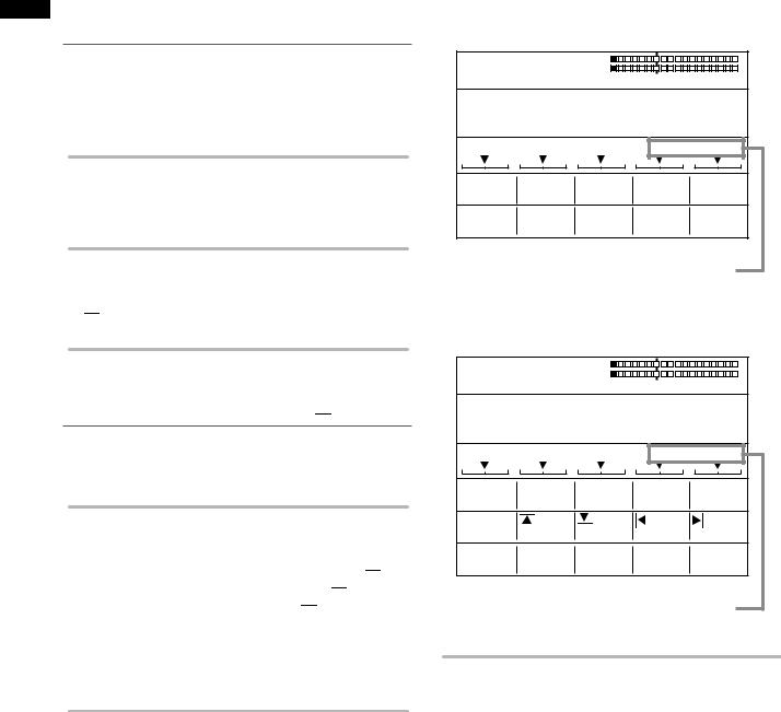
[MODIFY]
Settings can be made only for the basic patterns (the patterns shown as “Basic” in “List of Transition Patterns” at the back of this document) and their related patterns.
Rotary 1 Rotary 2 Rotary 3 Rotary 4 Rotary 5
MODIFY
OFF
OFF
COMP
SLIDE
MULTI
BLINDS
Select the effect to be applied to the pattern using the rotary 2 control.
When [COMP] is selected, the effect level ([SINGLE] or [DOUBLE]) can be set with the rotary 3 control.
[TRANSITION] menu
The items which can be set vary with the selected pattern.
POS. X 128 Y 128
Z 196
|
|
EVENT |
|
|
ME TIME |
PATTERN |
|
|
INT |
||||||||||||||||
|
|
00 E |
|
|
1:00 F |
0001 |
|
|
WHT |
||||||||||||||||
|
|
TRANSITION |
|
|
|
|
|
|
|
|
|
|
|
|
|
||||||||||
|
|
|
|
|
|
|
|
|
|
|
|
|
|
|
|
|
|
|
|
|
|
|
|
|
|
|
|
|
|
|
|
|
|
|
|
|
|
|
|
|
|
|
|
|
|
|
|
|
|
|
|
MODIFY |
|
|
OFF |
|
|
|
|
|
|
|
|
|
|
|
|
|
|
|
|
||||||
|
|
|
|
|
|
|
|
|
|
|
|
|
|
|
|
|
|
|
|
|
|
|
|||
|
|
|
|
|
|
|
|
|
|
|
|
|
|
|
|
|
|
|
|
|
|
|
|
|
|
PATTERN |
|
|
HARD |
|
|
WIDTH |
|
|
COLOR |
|
|
|
|
|
|||||||||||
|
|
EDGE |
|
|
|
|
|
0 |
|
|
WHITE |
|
|
|
|
|
|||||||||
|
|
|
|
|
|
|
|
|
|
|
|
|
|
|
|
|
|
|
|
|
|
|
|
|
|
EFFECTS |
|
|
OFF |
|
|
|
|
|
|
|
|
|
|
|
|
|
|
|
|
||||||
|
|
|
|
|
|
|
|
|
|
|
|
|
|
|
|
|
|
|
|
|
|
|
|||
NOTE
When a transition pattern in the range of No. 200 to No. 222 (1001 to 1004, 1021 to 1023, 1030 to 1034, and 1059 to 1069) is selected, transition mix is performed. (The MIX button is lighted.)
Of these patterns, when a pattern performing effects in which video and color effects are combined is selected, the VIDEO EFFECTS or COLOR EFFECTS button is lighted if turned
off, and the [VIDEO EFFECTS] or [COLOR EFFECTS] menu appears.
Modify |
Description |
Level |
Example |
|||||
COMP |
Reduced wipe |
[SINGLE]: Only |
|
|
|
|
|
|
|
|
|
|
|
|
|||
|
|
one image is |
|
|
|
|
|
|
|
|
|
|
|
|
|
|
|
|
|
reduced in size. |
|
|
|
|
|
|
|
|
[DOUBLE]: |
|
|
|
|
|
|
|
|
|
|
|
|
|
|
|
|
|
Both images are |
|
|
|
|
|
|
|
|
|
|
|
|
|
|
|
|
|
reduced in size. |
|
|
|
|
|
|
SLIDE |
Sliding one image |
None |
|
|
|
|
|
|
|
|
|
|
|
|
|||
|
into another |
|
|
|
|
|
|
|
|
|
|
|
|
|
|
|
|
|
|
|
|
|
|
|
|
|
MULTI |
Vertical-striped |
None |
|
|
|
|
|
|
|
|
|
|
|
|
|||
|
wipe |
|
|
|
|
|
|
|
|
|
|
|
|
|
|
|
|
BLINDS |
Blind-type wipe |
None |
|
|
|
|
|
|
|
|
|
|
|
|
|||
|
|
|
|
|
|
|
|
|
|
|
|
|
|
|
|
|
|
The factory default setting is [OFF].
The List of Transition Patterns at the back of this document can be used to check the basic patterns and those with the Modify effects added. (Example: When SLIDE as the MODIFY effect is applied to the No. 1 basic pattern, the No. 43 pattern is generated.)
NOTE
•If any change is made to [MODIFY], the pattern number is also changed automatically.
•When the internal video is selected as the video source after switching, the image is not reduced in size, but becomes the same state as [SINGLE] is selected even if [BOTH] is selected for [COMP].
•When one of the patterns in the range of No. 28 to No. 41 (1501 to 1510 and 1521 to 1530), No. 32 to No. 35, and No. 130 to No. 133 (1541 to 1548) with the [COMP] effect set is selected to use an input video source reduced in size, the multi-strobe effect in the [VIDEO EFFECT] menu cannot be applied. Even if the multi-strobe effect is selected, it is disabled when the transition lever is operated.
Sound and Video to ctsrChapteEff Applying 1
3

Sound and Video to ctsrChapteEff Applying 1
[PATTERN EDGE]
An edge can be added to a pattern.
Rotary 1 Rotary 2 Rotary 3 Rotary 4 Rotary 5
PATTERN |
HARD |
WIDTH |
COLOR |
|
EDGE |
32 |
WHITE |
|
|
|
|
|
|
|
|
HARD |
1-255 |
WHITE |
|
|
SOFT |
|
YELLOW |
|
|
BORDER |
|
CYAN |
|
|
SOFT BORDER |
|
GREEN |
|
|
|
|
MAGENTA |
|
|
|
|
RED |
|
|
|
|
BLUE |
|
|
|
|
BLACK |
|
|
|
|
CUSTOM1 |
|
|
|
|
CUSTOM2 |
|
Select the edge of transition patterns from [HARD], [SOFT], [BORDER], and [SOFT BORDER] using the rotary 2 control. The factory default setting is [HARD].
Set [WIDTH] in the range of 1 to 255 using the rotary 3 control.
The factory default setting is 32.
For No. 701 to No. 707 (24 to 27) and No. 801 to No. 814 (183 to 196) patterns, [WIDTH] can be set only to 1 or 2.
Use the rotary 4 control to set [COLOR] (color of the edge) to one of the colors in the table shown below.
Setting |
Color |
[WHITE] (factory default setting) |
White |
[YELLOW] |
Yellow |
[CYAN] |
Cyan |
[GREEN] |
Green |
[MAGENTA] |
Magenta |
[RED] |
Red |
[BLUE] |
Blue |
[BLACK] |
Black |
[CUSTOM1] or [CUSTOM2] |
Grey as the factory |
|
default setting |
When [CUSTOM1] or [CUSTOM2] is selected, the same color as set in the [BACK MATTE] submenu of the [INT VIDEO] menu is applied ( page Vol.1-29).
NOTE
•If the PinP pattern is selected and Still is applied to source video B, Still is cancelled at the same time as the transition lever is operated. (The PinP pattern and Still cannot be used as the same time.)
•[SOFT BORDER] cannot be selected for No. 701 to No. 707 (24 to 27) and No. 801 to No. 814 (183 to 196) patterns.
[EFFECTS]
Select the effect of [SHADOW] or [TRAIL] using the rotary 2 control.
SHADOW: Adds black shadow to the pattern. TRAIL: Leaves trails of the moving pattern. Select [OFF] to apply no effect.
Rotary 1 Rotary 2 Rotary 3 Rotary 4 Rotary 5
EFFECTS
OFF
OFF
SHADOW
TRAIL
If [SHADOW] is selected
Rotary 1 Rotary 2 Rotary 3 Rotary 4 Rotary 5
EFFECTS SHADOW
Set the position of the shadow by operating the joystick while holding down the SHIFT key.
The CENTER, SCENE GRABBER, and HOLD buttons flash temporarily.
To cancel the shadow position setting, press the  key while holding down the SHIFT key in the state where [FEECTS] is selected (inverted to black). At the same time as the setting becomes [OFF], the specified shadow position is reset.
If [TRAIL] is selected
Rotary 1 Rotary 2 Rotary 3 Rotary 4 Rotary 5
EFFECTS |
TARIL |
|
SELF |
TIME 16 |
|
|
|
|
|
|
|
|
|
SELF |
|
1-32 |
|
|
|
SELF-SPARK |
|
|
|
|
|
BODM |
|
|
|
|
|
BODM-SPARK |
|
|
|
Select the spark for the trail (the twinkling effect of trails) from [SELF] (original video), [SELF-SPARK] (spark of original video), [BODM] (border color), and [BODMSPARK] (border spark) using the rotary 3 control.
When [BODM] or [BODM SPARK] is selected, the color set in the [PATTERN EDGE] submenu of the [TRANSITION] menu is used as the border color.
Set the continuation time of the trail in the range of 1 to 32 using the rotary 4 control.
To set the offset position of the trail, operate the joystick while holding down the SHIFT key.
The CENTER, SCENE GRABBER, and HOLD buttons flash temporarily.
The offset position setting can be cancelled in the same way as for canceling the shadow position setting.
NOTE
The trail or shadow settings are canceled when TRAIL or SHADOW is selected in the [DSK EFFECTS] submenu of the [DSK FADE] menu or when the multi-strobe effect or DECAY is selected in the [VIDEO EFFECTS] menu.
4

Setting the Basic Pattern Key
[BASIC PATTERN KEY]/Pattern Key
[PATTERN KEY]
The [BASIC PATTERN KEY] menu or [PATTERN KEY] menu is used to create a key with key patterns.
The [BASIC PATTERN KEY] menu appears when the selected pattern has a number in the range of 3001 to 3046, and the [PATTERN KEY] menu appears when the selected pattern has a number of 3301 or larger.
For pattern numbers, refer to “List of Key Patterns” at the back of Volume 2.
[BASIC PATTERN KEY] menu
This menu is displayed when the selected pattern has a number in the range of No. 3001 to No. 3046.
POS. X 128 Y 128
Z 196
|
|
EVENT |
|
|
|
ME TIME |
PATTERN |
|
|
|
INT |
||||||||||||||||||
|
|
00 E |
|
|
|
1:00 F |
3001 |
|
|
WHT |
|||||||||||||||||||
BASIC PATTERN KEY |
|
|
|
|
|
|
|
|
|
|
|
|
|
|
|
||||||||||||||
|
|
|
|
|
|
|
|
|
|
|
|
|
|
|
|
|
|
|
|
|
|
|
|
|
|
|
|
|
|
|
|
|
|
|
|
|
|
|
|
|
|
|
|
|
|
|
|
|
|
|
|
|
|
|
|
|
|
|
|
PATTERN |
|
|
|
HARD |
|
WIDTH |
|
|
|
COLOR |
|
|
K LEVEL |
||||||||||||||||
|
|
|
|
|
|
||||||||||||||||||||||||
|
|
EDGE |
|
|
|
|
|
|
|
16 |
|
|
|
WHITE |
|
255 |
|||||||||||||
EFFECTS |
|
|
|
OFF |
|
|
|
|
|
|
|
|
|
|
|
|
|
|
|
|
|
|
|
||||||
|
|
|
|
|
|
|
|
|
|
|
|
|
|
|
|
|
|
|
|
|
|
||||||||
|
|
|
|
|
|
|
|
|
|
|
|
|
|
|
|
|
|
|
|
|
|
|
|
|
|
|
|||
|
|
|
|
|
|
|
|
|
|
|
|
|
|
|
|
|
|
|
|
|
|
|
|
|
|
|
|
|
|
KEY |
|
|
|
EMPTY |
|
|
|
|
|
|
SETUP |
|
|
|
|
|
|
||||||||||||
|
|
|
|
|
|
|
|
|
|
|
|
|
|||||||||||||||||
|
|
LEARN |
|
9000 |
|
|
|
|
|
|
|
|
|
|
|
|
|||||||||||||
[PATTERN KEY] menu
This menu is displayed when the selected pattern has No. 3301 or larger.
The [PATTERN KEY] menu allows you to make settings for video cropping.
POS. |
X 128 |
Y 128 |
|
|
|
|
|
Z 196 |
|
|
|
|
|
EVENT |
ME TIME |
PATTERN |
INT |
|||
00 E |
1:00 F |
3301 |
WHT |
|||
PATTERN KEY |
|
|
|
|
||
PATTERN |
|
WIDTH |
COLOR |
K LEVEL |
||
EDGE |
HARD |
16 |
WHITE |
255 |
||
CROP |
|
|
0 |
0 |
0 |
0 |
|
|
|
||||
EFFECTS |
|
OFF |
|
|
|
|
|
|
|
|
|
|
|
KEY |
|
|
EMPTY |
|
SETUP |
|
LEARN |
|
9000 |
|
|
||
Scroll the screen to display.
[PATTERN EDGE]
The items other than [K LEVEL] can be set in the same way as the transition (wipe) pattern ( page 4).
For [K LEVEL], set the key level (transparency level of the key) in the range of 0 to 255 using the rotary 5 control. The smaller the setting value, the higher the transparency. When 0 is set, the key disappears entirely (becomes transparent).
The key registered in the direct patterns can be individually set for each pattern.
[CROP] (for [PATTERN KEY] menu only)
Video used as the key can be cropped.
Rotary 1 Rotary 2 Rotary 3 Rotary 4 Rotary 5
CROP |
|
|
|
|
|
|
|
|
|
0 |
|
|
|
|
|
|
|
||
0 |
|
0 |
|
0 |
|||||
|
|
|
|||||||
|
|
|
|
|
|
|
|
|
|
|
0-243(480i) |
|
0-243(480i) |
|
0-720(480i) |
0-720(480i) |
|||
|
0-288(576i) |
|
0-288(576i) |
|
0-720(576i) |
0-720(576i) |
|||
|
0-720(720p) |
|
0-720(720p) |
|
0-1280(720p) |
0-1280(720p) |
|||
|
0-540(1080i) |
|
0-540(1080i) |
|
0-1920(1080i) |
0-1920(1080i) |
|||
|
|
|
|
|
|
|
|
|
|
Set the top edge of the video in the range of 0 to 243 (480i)/288 (576i)/720 (720P)/540 (1080i) using the rotary 2 control.
The factory default setting is 0.
Set the bottom edge of the video in the range of 0 to 243 (480i)/288 (576i)/720 (720P)/540 (1080i) using the rotary 3 control.
The factory default setting is 0.
Set the left edge of the video in the range of 0 to 720 (480i/576i)/1280 (720P)/1920 (1080i) using the rotary 4 control.
The factory default setting is 0.
Set the right edge of the video in the range of 0 to 720 (480i/576i)/1280 (720P)/1920 (1080i) using the rotary 5 control.
The factory default setting is 0.
For top and bottom edge settings, when one is increased, the other may be decreased to prevent the total value of both settings from exceeding the maximum value.
For right and left edge settings, when one is increased, the other may be decreased to prevent the total value of both settings from exceeding the maximum value.
[EFFECTS]
Settings can be made in the same way as in the [EFFECTS] submenu of the [TRANSITION] menu ( page 4).
[KEY LEARN]
See “Setting Key Learn [KEY LEARN]” ( page 9).
Sound and Video to ctsrChapteEff Applying 1
5

Sound and Video to ctsrChapteEff Applying 1
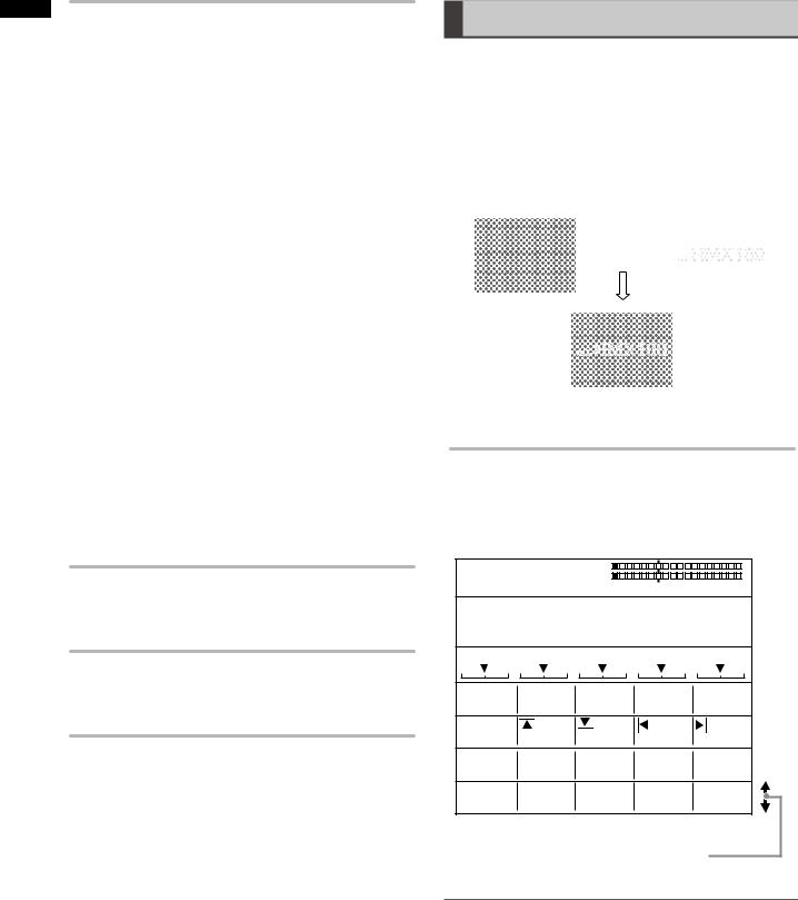
Setting the Chroma Key
[CHROMA KEY]
Chroma keying is a function for removing a specified color range from one image and keying another image to the range.
The following diagram shows an example of the chroma key.
Key is specified by color on which the cursor is placed, and removed.
The [CHROMA KEY] menu is used to create a chroma key.
[CHROMA KEY] menu
The menu appears when the CHROMA KEY (chroma key) button is pressed in the PATTERN area ( page Vol.1-14) or the pattern of No. 62 is selected.
ME preview is automatically chosen, and the video to be keyed with the chroma key cursor is output from the preview output connector.
Shows the selected number: |
|
|
|
|
|
|
|
|
|
|
|
|
|
|
|
|
|
Shows the selected |
|||||||||||||||||||||||||||||||||||||||||
1, 2, or 3. |
|
|
|
|
|
|
|
|
|
|
|
|
|
|
|
|
|
|
|
|
|
|
|
|
|
|
|
|
|
|
|
|
|
|
|
|
|
|
|
|
|
|
|
|
|
|
|
|
|
|
|
color. |
|||||||
|
|
|
|
|
|
|
|
|
|
|
|
|
|
|
|
|
|
|
|
|
|
|
|
|
|
|
|
|
|
|
|
|
|
|
|
|
|
|
|
|
|
|
|
|
|
|
|
|
|
|
|
|
|
||||||
|
|
|
|
|
|
|
|
|
|
|
|
|
|
|
|
|
|
|
|
|
|
|
|
|
|
|
|
|
|
|
|
|
|
|
|
|
|
|
|
|
|
|
|
|
|
|
|
|
|
|
|
|
|
|
|
|
|
|
|
|
|
|
POS. X 128 Y 128 |
|
|
|
|
|
|
|
|
|
|
|
|
|
|
|
|
|
|
|
|
|
|
|
|
|
|
|
|
|
|
|
|
|
|
|
|
|
|
|
|
|
|
||||||||||||||
|
|
|
Z 196 |
|
|
|
|
|
|
|
|
|
|
|
|
|
|
|
|
|
|
|
|
|
|
|
|
|
|
|
|
|
|
|
|
|
|
|
|
|
|
|
|
|
|
|
|
|
|
||||||||||
|
|
|
|
|
|
|
|
|
|
|
|
|
|
|
|
|
|
|
|
|
|
|
|
|
|
|
|
|
|
|
|
|
|
|
|
|
|
|
|
|
|
|
|
|
|
|
|
|
|
|
|
|
|
|
|
|
|||
|
|
|
EVENT |
|
|
|
ME TIME |
|
PATTERN |
|
|
|
|
|
INT |
|
|
|
|||||||||||||||||||||||||||||||||||||||||
|
|
|
00 E |
|
|
|
1:00 F |
0062 |
|
|
|
|
|
WHT |
|
|
|
||||||||||||||||||||||||||||||||||||||||||
|
|
|
CHROMA KEY 1 |
|
|
|
R=- - - |
|
|
|
G=- - - B=- - - |
|
|
|
|
||||||||||||||||||||||||||||||||||||||||||||
|
|
|
|
|
|
|
|
|
|
|
|
|
|
||||||||||||||||||||||||||||||||||||||||||||||
|
|
|
|
|
|
|
|
|
|
|
|
|
|
|
|
|
|
|
|
|
|
|
|
|
|
|
|
|
|
|
|
|
|
|
|
|
|
|
|
|
|
|
|
|
|
|
|
|
|
|
|
|
|
|
|
|
|
|
|
|
|
|
|
|
|
|
|
|
|
|
|
|
|
|
|
|
|
|
|
|
|
|
|
|
|
|
|
|
|
|
|
|
|
|
|
|
|
|
|
|
|
|
|
|
|
|
|
|
|
|
|
|
|
|
|
|
|
|
|
|
|
KEY |
|
COLOR |
|
|
SLICE 1 |
|
|
SLOPE 1 |
|
K LEVEL |
|
|
|
||||||||||||||||||||||||||||||||||||||||||||
|
|
|
|
|
|
||||||||||||||||||||||||||||||||||||||||||||||||||||||
|
|
|
|
|
|
|
1 |
|
|
|
|
128 |
|
8 |
|
|
255 |
|
|
|
|||||||||||||||||||||||||||||||||||||||
|
|
COLOR |
|
OFFSET |
|
|
C SLICE |
|
|
C-AREA |
|
|
MONO L |
|
|
|
|||||||||||||||||||||||||||||||||||||||||||
|
|
|
|
|
|
|
|
|
|||||||||||||||||||||||||||||||||||||||||||||||||||
|
|
|
CANCEL |
|
128 |
|
|
|
|
128 |
|
3 |
|
|
6 |
|
|
|
|||||||||||||||||||||||||||||||||||||||||
|
|
|
|
|
|
|
|
|
|
|
|
|
|
|
|
|
|
|
|
|
|
|
|
|
|
|
|
|
|
|
|
|
|
|
|
|
|
|
|
|
|
|
|
|
|
|
|
|
|
|
|
|
|
|
|
|
|
|
|
|
|
CROP |
|
|
|
|
|
|
|
|
|
|
|
|
0 |
|
|
0 |
|
|
|
|
|
0 |
|
|
|
||||||||||||||||||||||||||||||||
|
|
|
0 |
|
|
|
|
|
|
|
|
|
|
|
|
|
|
||||||||||||||||||||||||||||||||||||||||||
|
|
|
|
|
|
|
|
|
|
|
|
|
|
|
|
|
|
|
|
|
|||||||||||||||||||||||||||||||||||||||
|
|
|
|
|
|
|
|
|
|
|
|
|
|
|
|
|
|
|
|
|
|
|
|
|
|
|
|
|
|
|
|
|
|
|
|
|
|
|
|
|
|
|
|
|
|
|
|
|
|
|
|
|
|
|
|
|
|
|
|
|
|
EFFECTS |
|
|
|
|
OFF |
|
|
|
|
|
|
|
|
|
|
|
|
|
|
|
|
|
|
|
|
|
|
|
|
|
|
|
|
|
|
|
|
|
|
|
|
|
|
|
|
|
|
|
|
|
|
||||||
|
|
|
|
|
|
|
|
|
|
|
|
|
|
|
|
|
|
|
|
|
|
|
|
|
|
|
|
|
|
|
|
|
|
|
|
|
|
|
|
|
|
|
|
|
|
|
|
|
|
|
|
||||||||
|
|
|
|
|
|
|
|
|
|
|
|
|
|
|
|
|
|
|
|
|
|
|
|
|
|
|
|
|
|
|
|
|
|
|
|
|
|
|
|
|
|
|
|
|
|
|
|
|
|
|
|
|
|
|
|
||||
|
|
BORDER |
|
COLOR |
|
|
|
|
|
|
|
|
|
|
|
|
|
|
|
|
|
|
|
|
|
|
|
|
|
|
|
|
|
|
|
|
|
|
|
|
|
|
|
|
|
|
|
|
|
|
|||||||||
|
|
|
|
|
|
|
|
|
|
WHITE |
|
|
|
|
|
|
|
|
|
|
|
|
|
|
|
|
|
|
|
|
|
|
|
|
|
|
|
|
|
|
|
|
|
|
|
|
|
|
|
|
|
|
|
|
|
|
|||
|
|
|
|
|
|
|
|
|
|
|
|
|
|
|
|
|
|
|
|
|
|
|
|
|
|
|
|
|
|
|
|
|
|
|
|
|
|
|
|
|
|
|
|
|
|
|
|
|
|
|
|
|
|
|
|
|
|
|
|
Scroll the screen to display.
[KEY]
Up to three colors to be removed from an image can be stored.
Rotary 1 Rotary 2 Rotary 3 Rotary 4 Rotary 5
KEY |
COLOR |
SLICE 1 |
SLOPE 1 |
K LEVEL |
|
1 |
128 |
8 |
255 |
|
|
|
|
|
|
1-3 |
0-255 |
0-15 |
0-255 |
|
|
|
|
|
After selecting the number using the rotary 2 control, move the chroma key cursor on the preview image to the color (blue for example) to be removed using the joystick, and press the  key.
key.
The numeric values of the stored color are displayed for R, G, and B, respectively, in the menu. (“---” appears when the color is not stored.)
The color can be stored any number of times by pressing the  key. However, the color data is overwritten each time it is stored.
To cancel the stored color, enter the selected number using the numeric keys while holding down the SHIFT key.
To set the chroma key in detail
The color density and range can be specified to designate more precise keying.
Set [SLICE] of the selected color in the range of 0 to 255 using the rotary 3 control.
The slice is set to specify the color density (saturation) in the area to be removed. For example, if you specify blue using the joystick, the setting value can be increased to remove only blue darker than the specified blue.
Set [SLOPE] of the selected color in the range of 0 to 15 using the rotary 4 control.
The slope is set to specify the range (hue) of the color to be removed. For example, if you specify blue using the joystick, the setting value can be increased to remove only blue closest to the specified blue.
Set [K LEVEL] (transparency level of the key) in the range of 0 to 255 using the rotary 5 control.
NOTE
The value set with the rotary 3 control is saved for each of the three key colors, while the value set with the rotary 5 control is applied to all stored colors.
[COLOR CANCEL]
The appearance of color blur can be diminished in the boundary area of the key.
Rotary 1 Rotary 2 Rotary 3 Rotary 4 Rotary 5
COLOR |
OFFSET |
C SLICE |
C-AREA |
MONO L |
CANCEL |
128 |
128 |
3 |
6 |
|
|
|
|
|
|
0-255 |
0-255 |
0-3 |
0-15 |
|
|
|
|
|
Set [OFFSET] (offset from the key) in the range of [0] to [255] using the rotary 2 control.
Set [C SLICE] (cancel slice) in the range of [0] to [255] using the rotary 3 control.
6

Set [C-AREA] (cancel area) in the range of [0] to [3] using the rotary 4 control.
Set [MONO L] (mono level) in the range of [0] to [15] using the rotary 5 control.
[CROP]
Settings can be made in the same way as in the [CROP] submenu of the [PATTERN KEY] menu ( page 5).
[EFFECTS]
Settings can be made in the same way as in the [EFFECTS] submenu of the [TRANSITION] menu ( page 4).
[BORDER]
Use the rotary 2 control to set [COLOR] (color of the edge) to one of the colors in the table shown below.
Setting |
Color |
[WHITE] (factory default setting) |
White |
[YELLOW] |
Yellow |
[CYAN] |
Cyan |
[GREEN] |
Green |
[MAGENTA] |
Magenta |
[RED] |
Red |
[BLUE] |
Blue |
[BLACK] |
Black |
[CUSTOM1] or [CUSTOM2] |
Grey as the factory |
|
default setting |
When [CUSTOM1] or [CUSTOM2] is selected, the same color as set in the [BACK MATTE] submenu of the [INT VIDEO] menu is applied ( page Vol.1-28).
If [TRAIL] is selected in the [EFFECTS] submenu, the color set in the [BORDER] submenu is used as the border color when [BODM] or [BODM SPARK] is selected.
Setting the Luminance Key
[LUMINANCE KEY] /External Key
[EXT KEY]
Luminance keying is a function for creating a key with the specific brightness (luminance) of one image as the reference and keying to another image.
External keying is a function for keying a specified extraneous image. The external keying function enables keying of an image which is not assigned as the input source.
The following diagram shows an example of the luminance key.
Bright area is removed as key.
The [LUMINANCE KEY] menu is used to create a luminance key.
The [EXT KEY] menu is used to create an external key.
[LUMINANCE KEY] menu
The menu appears when the LUM KEY button is pressed in the PATTERN area ( page Vol.1-14) or the pattern of No. 61 is selected.
POS. X 128 Y 128
Z 196
|
|
EVENT |
|
|
|
ME TIME |
PATTERN |
|
|
|
|
INT |
|||||||||||||||||||
|
|
00 E |
|
|
|
1:00 F |
0061 |
|
|
WHT |
|||||||||||||||||||||
LUMINANCE KEY |
|
|
|
|
|
|
|
|
|
|
|
|
|
|
|
||||||||||||||||
|
|
|
|
|
|
|
|
|
|
|
|
|
|
|
|
|
|
|
|
|
|
|
|
|
|
|
|
|
|
||
|
|
|
|
|
|
|
|
|
|
|
|
|
|
|
|
|
|
|
|
|
|
|
|
|
|
|
|
|
|
|
|
KEY |
|
|
|
|
|
|
|
|
|
|
SLICE |
0 |
|
|
SLOPE |
|
K LEVEL |
||||||||||||||
|
|
|
|
||||||||||||||||||||||||||||
|
|
|
|
|
|
|
|
|
|
|
|
|
|
|
|
|
|
15 |
|
255 |
|||||||||||
CROP |
|
|
|
|
|
|
|
|
|
|
|
|
0 |
|
|
0 |
|
|
|
|
0 |
||||||||||
|
0 |
|
|
|
|
|
|
|
|
|
|
|
|||||||||||||||||||
|
|
|
|
|
|
|
|
|
|
|
|
|
|
|
|
|
|||||||||||||||
EFFECTS
OFF
BORDER COLOR
WHITE
Scroll the screen to display.
[EXT KEY] menu
The menu appears when the EXT KEY button is pressed in the PATTERN area ( page Vol.1-14) or the pattern of No. 59 is selected.
POS. X 128 |
Y 128 |
|
|
|
|
|
|
|
|
|
|
|
|
|
|
|
|
|
|
|
|
|
|
|
|
|
|
|
|
|
|
|
|
|
|
|
|
|
|
|
||||||||||||||||
|
|
|
|
|
|
|
|
|
|
|
|
|
|
|
|
|
|
|
|
|
|
|
|
|
|
|
|
|
|
|
|
|
|
|
|
|
|
|
||||||||||||||||||
|
|
Z 196 |
|
|
|
|
|
|
|
|
|
|
|
|
|
|
|
|
|
|
|
|
|
|
|
|
|
|
|
|
|
|
|
|
|
|
|
|
|
|
|
|
|
|
|
|
|
|
|
|||||||
|
|
|
|
|
|
|
|
|
|
|
|
|
|
|
|
|
|
|
|
|
|
|
|
|
|
|
|
|
|
|
|
|
|
|
|
|
|
|
|
|
|
|
|
|
|
|
|
|
|
|
|
|
|
|
|
|
|
|
EVENT |
|
|
|
ME TIME |
PATTERN |
|
|
|
|
|
INT |
|||||||||||||||||||||||||||||||||||||||||||
|
|
00 E |
|
|
|
1:00 F |
0059 |
|
|
|
|
|
WHT |
|||||||||||||||||||||||||||||||||||||||||||
EXT KEY |
|
|
|
|
|
|
|
|
|
|
|
|
|
|
|
|
|
|
|
|
|
|
|
|
|
|
|
|
|
|
|
|
|
|
|
|
|
|
|
|
|
|
|
|
|
|
|
|
|
|
|
|
||||
|
|
|
|
|
|
|
|
|
|
|
|
|
|
|
|
|
|
|
|
|
|
|
|
|
|
|
|
|
|
|
|
|
|
|
|
|
|
|
|
|
|
|
|
|
|
|
|
|
|
|
|
|
|
|
||
|
|
|
|
|
|
|
|
|
|
|
|
|
|
|
|
|
|
|
|
|
|
|
|
|
|
|
|
|
|
|
|
|
|
|
|
|
|
|
|
|
|
|
|
|
|
|
|
|
|
|
|
|
|
|
|
|
KEY |
|
KEY |
SDI1 |
|
|
|
SLICE |
0 |
|
|
SLOPE |
|
|
K LEVEL |
||||||||||||||||||||||||||||||||||||||||||
|
|
|
|
|||||||||||||||||||||||||||||||||||||||||||||||||||||
|
|
|
|
|
|
|
|
|
|
|
|
|
|
|
|
|
15 |
|
|
255 |
||||||||||||||||||||||||||||||||||||
CROP |
|
|
|
|
|
0 |
|
|
|
|
|
|
0 |
|
|
0 |
|
|
|
|
|
0 |
||||||||||||||||||||||||||||||||||
|
|
|
|
|
|
|
|
|
|
|
|
|
|
|
|
|
|
|||||||||||||||||||||||||||||||||||||||
|
|
|
|
|
|
|
|
|
|
|
|
|
|
|
|
|
|
|
|
|
|
|
||||||||||||||||||||||||||||||||||
EFFECTS
OFF
BORDER COLOR
WHITE
Scroll the screen to display.
Sound and Video to ctsrChapteEff Applying 1
7
Sound and Video to ctsrChapteEff Applying 1
[KEY]
Set [KEY] (key signal) to one of the following using the rotary 2 control (for [EXT KEY] menu only).
When the system format is set to HD ( page Vol.1-19):
SDI1, SDI2, SDI3, SDI4, HDMI1, HDMI2, DVI-I
When the system format is set to SD ( page Vol.1-19):
SDI1, SDI2, SDI3, SDI4, VIDEO1, VIDEO2, DVI-I
The factory default setting is [SDI1] in each case.
To set the luminance key in detail
The color density and luminance level range can be specified to designate more precise keying.
Set [SLICE] (slice level) in the range of [0] to [255] using the rotary 3 control.
The factory default setting is [0].
The slice is set to specify the brightness level of the area to be removed. The setting value can be increased to remove only the area brighter than the specified area.
Set [SLOPE] in the range of [0] to [15] using the rotary 4 control.
The factory default setting is [15].
The slope is set to specify the luminance level range of the area to be removed. The setting value can be increased to remove only the area of the luminance level closest to the specified level.
Set [K LEVEL] (transparency level of the key) in the range of [0] to [255] using the rotary 5 control.
The factory default setting is [255].
[CROP]
Settings can be made in the same way as in the [CROP] submenu of the [PATTERN KEY] menu ( page 5).
[EFFECTS]
Settings can be made in the same way as in the [EFFECTS] submenu of the [TRANSITION] menu ( page 4).
[BORDER]
Settings can be made in the same way as in the [BORDER] submenu of the [CHROMA KEY] menu ( page 7).
Setting the Title Key [TITLE KEY]
A still picture saved in memory from the [DSK] menu can be keyed as a title.
Title keys are saved as patterns of the numbers with “1” as the last digit every 10th (9511, 9521,…) in the range of 9501 to 9791. (The number of patterns that can be
saved varies with the setting in the [MEMORY] submenu of [SETUP] menu.)
See “[DSK SOURCE]” for saving title keys ( page 11).
The following diagram shows an example of the title key.
|
|
|
|
|
|
|
|
|
|
|
|
|
|
|
Back matte video |
Title |
|||
|
|
|
|
|
|
|
|
|
|
The [TITLE KEY] menu is used to create a title key.
[TITLE KEY] menu
The menu appears when a still picture saved in title memory is called with the pattern number 9501 or larger from the [DSK SOURCE] > [MODE] submenu of the [DSK FADE] menu ( page 11).
POS. X 128 Y 128 |
|
|
|
||
Z 512 |
|
|
|
||
EVENT |
ME TIME |
PATTERN |
INT |
||
00 E |
02:00 F |
9501 |
WHT |
||
TITLE KEY |
|
|
|
||
KEY |
SLICE |
0 |
SLOPE |
K LEVEL |
|
CROP |
|
15 |
255 |
||
0 |
0 |
0 |
0 |
||
|
|||||
EFFECTS |
OFF |
|
|
|
|
|
|
|
|
||
BORDER |
COLOR |
|
|
|
|
|
WHITE |
|
|
|
|
Scroll the screen to display.
NOTE
•The title keys saved in memory are erased when the power is turned off. Since memory is empty when the unit is restarted, the [TITLE KEY] menu is not displayed even if a pattern number of the title key after No. 9501 is specified.
•When a title key is called during execution of the downstream key, [DSK EFECTS] (DSK effect) is set to [OFF].
•Title keys cannot be set if the title memory count is set to 0 in the [MEMORY] submenu of the [SETUP] menu ( page 27).
8

[KEY]
Settings can be made in the same way as in the [KEY] submenu of the [LUMINANCE KEY] menu ( page 8).
[CROP]
Settings can be made in the same way as in the [CROP] submenu of the [PATTERN KEY] menu ( page 5).
[EFFECTS]
Settings can be made in the same way as in the [EFFECTS] submenu of the [TRANSITION] menu ( page 4).
[BORDER]
Settings can be made in the same way as in the [BORDER] submenu of the [CHROMA KEY] menu ( page 7).
Setting Key Learn [KEY LEARN]
The key learn function allows storing the key frame settings (XYZ and key level) in memory and calling them to reproduce the animation effect.
A key frame refers to a frame which defines changes of the video used for animation. Several points where a shape
or position of an object is changed can be set in the key frame to create smooth animation through interpolation between the points.
With the [(BASIC) PATTERN KEY] menu, the rotary 1 control can be operated to select [KEY LEARN] to set key learn
in the currently selected key pattern and register the key pattern as a pattern in the range of No. 9000 to No. 9019.
Rotary 1 Rotary 2 Rotary 3 Rotary 4 Rotary 5
KEY |
EMPTY |
SETUP |
|
LEARN |
9000 |
|
|
|
|
|
|
|
9000-9019 |
SETUP |
|
|
|
CLR |
|
|
|
ALL CLR |
|
To select the number applied to the pattern in which key learn is set
Operate the rotary 2 control to select the pattern number in the range of 9000 to 9019.
When the number of the pattern with key learn set is selected, [SAVED] is diplayed. When the number of the pattern with no key learn set isselected, [EMPTY] is displayed.
To edit key learn
Select [SETUP] using the rotary 4 control, and press the 
 key.
key.
The Key Learn Editing screen appears.
When the 
 key is pressed with [SAVED] displayed for the selected pattern, the message [OK?] appears.
In this case, press the  key again to display the Key Learn Editing screen.
NOTE
When key learn that is already registered in a pattern is edited, the settings of the original pattern before key learn was set are given priority. Thus, even if the pattern with key learn set is called and [SETUP] is selected, no change is given to the base pattern.
For key learn in a different pattern, it is recommended to use a pattern number for which EMPTY is displayed or to delete the existing key learn pattern once and set a new key learn pattern.
Key Learn Editing screen
POS. X 128 Y 128
Z 196
EVENT |
|
ME TIME |
PATTERN |
INT |
|||
00 E |
|
1:00 F |
3001 |
WHT |
|||
KEY |
|
9000 |
|
|
|
|
|
|
|
|
|
|
|
||
LEARN |
|
|
|
|
|
|
|
INSERT |
|
BASIC |
|
|
|
||
REPLACE |
|
|
|
|
|||
|
|
|
|
||||
CLR KF |
|
K FRAME |
|
|
|
|
K LEVEL |
|
|
|
|
||||
COPY |
|
0 |
|
|
|
|
255 |
PASTE |
|
|
|
|
|
|
|
|
|
|
|
|
|
|
|
EXIT |
|
|
|
|
|
|
|
To select the key frame number
The key frame number is shown under [K FRAME]. When selecting the key frame number to copy the key frame or specify a position for inserting the key frame, select it from the registered key frame numbers using the rotary 2 control while holding down the SHIFT key.
To set the key frame
Select the editing item including the key position (X, Y, and Z), aspect, and time using the rotary 1 control, and proceed with the setting of the key frame. To execute each editing item, press the 
 key.
key.
INSERT: Inserts a key frame in the place of the next key frame.
REPLACE: Replaces the current key frame. CLR KF: Deletes the current key frame. COPY: Copies the current key frame.
PASTE: Pastes a copied key frame by overwriting. EXIT: Cancels the key learn editing mode and saves the
key learn settings.
To set the time up to the current key frame, a value is input for [ME TIME] with the numeric keys or the TIME rotary control.
The set time is shown under [ME TIME] on the setting screen ( page Vol.1-20).
Upon completion of registration, select [EXIT] using the rotary 1 control and press the 
 key to fix the key frame settings.
Sound and Video to ctsrChapteEff Applying 1
9
Sound and Video to ctsrChapteEff Applying 1
The menu returns to the original [(BASIC) PATTERN KEY] menu.
NOTE
The key position, time, and other items set for the key frames cannot be changed. To change those items, delete the applicable key frame and set a new key frame. When inserting a key frame, be sure to complete the time setting in advance.
To set the transparency level of the key
Set [K LEVEL] in the range of [0] to [255] using the rotary 5 control while holding down the SHIFT key.
To make settings for other key pattern
By using the rotary 1 control to select [EXIT] and pressing the 
 key, cancel the key learn editing mode, select the key pattern, and display the key learn editing screen again.
To preview the operation of the key
Select the pattern with [SAVED] indicated, use the rotary 4 control to select [PREVIEW], and press the 
 key
key
NOTE
[PREVIEW] is displayed only when settings have been made in the menu for the same pattern as that with key learn set.
To delete a key learn pattern
Select the pattern with [SAVED] indicated, use the rotary 4 control to select [CLR] or [ALL CLR], and press the 
 key. When the message [OK?] appears, press the
 key again. To cancel the pattern deletion, press the
 key while holding down the SHIFT key.
When [CLR] is selected, the currently selected key learn pattern is deleted. When [ALL CLR] is selected, all key learn patterns are deleted.
To use a pattern with key learn set
Key learn is set in the patterns in the range of No. 9000 to No. 9019.
When one of those patterns is selected, [(BASIC) PATTERN KEY] menu for No. 9000 to No. 9019 patterns appears. ([KEY LEARN] is not displayed as the setting item.)
If key learn is set in the selected pattern in the range of No. 3001 to No. 3046, the [BASIC PATTERN KEY] menu appears. If key learn is set in the selected pattern of No. 3301 or larger, the [PATTERN KEY] menu appears.
[BASIC PATTERN KEY] menu (original pattern No. 3001 to No. 3046)
POS. X 128 Y 128 |
|
|
|
|
Z 196 |
|
|
|
|
EVENT |
ME TIME |
PATTERN |
INT |
|
00 E |
1:00 F |
9000 |
WHT |
|
BASIC PATTERN KEY |
|
ORIGINAL 3001 |
||
PATTERN |
WIDTH |
COLOR |
K LEVEL |
|
EDGE |
HARD |
16 |
WHITE |
255 |
EFFECTS |
OFF |
|
|
|
|
|
|
|
|
Original pattern number
[PATTERN KEY] menu (original pattern No. 3301 or larger)
POS. |
X 128 |
Y 128 |
|
|
|
|
|
Z 196 |
|
|
|
|
|
EVENT |
ME TIME |
PATTERN |
INT |
|||
00 E |
1:00 F |
9001 |
WHT |
|||
PATTERN KEY |
|
|
ORIGINAL 3301 |
|||
PATTERN |
|
WIDTH |
COLOR |
K LEVEL |
||
EDGE |
HARD |
16 |
WHITE |
255 |
||
CROP |
|
|
0 |
0 |
0 |
0 |
|
|
|
||||
EFFECTS |
|
OFF |
|
|
|
|
|
|
|
|
|
|
|
Original pattern number
To execute key learn
Set the items in the [(BASIC) PATTERN KEY] menu, and press the AUTO TAKE button.
10
Setting the Downstream Key (DSK)
A downstream key refers to a key which is mixed at the end of the effects including transition and keying. A key that you want to display in the foreground of an image is set as a downstream key.
The set downstream key can be saved as a title key in memory.
The [DSK FADE] menu is used to insert the downstream key.
[DSK FADE] menu
This menu appears when the DSK FADE button is pressed or the DSK selector button is pressed for preview of the downstream key.
POS. X 128 Y 128
Z 512
|
|
EVENT |
|
|
|
ME TIME |
PATTERN |
|
|
|
|
INT |
|||||||||||||||||||
|
|
00 E |
|
|
|
2:00 F |
9501 |
|
|
WHT |
|||||||||||||||||||||
|
|
DSK FADE |
|
|
|
|
|
|
|
|
|
|
|
|
|
|
|
|
|
|
|
|
|||||||||
|
|
|
|
|
|
|
|
|
|
|
|
|
|
|
|
|
|
|
|
|
|
|
|
|
|
|
|
||||
|
|
|
|
|
|
|
|
|
|
|
|
|
|
|
|
|
|
|
|
|
|
|
|
|
|
|
|
|
|
|
|
DSK |
|
KEY |
|
|
|
FILE |
|
|
PAGE |
|
MODE |
||||||||||||||||||||
|
|
|
|
||||||||||||||||||||||||||||
|
|
SOURCE |
|
|
|
|
SDI1 |
|
|
|
|
|
SDI1 |
|
1 |
|
|
|
|
WRITE |
|||||||||||
DSK |
|
SLICE |
|
|
|
SLOPE |
|
|
REVERSE |
|
K LEVEL |
||||||||||||||||||||
|
|
|
|
||||||||||||||||||||||||||||
|
|
KEY |
|
0 |
|
|
|
|
|
8 |
|
|
OFF |
|
255 |
||||||||||||||||
|
|
|
|
|
|
|
|
|
|
|
|
|
|
|
|
|
|
|
|
|
|
|
|
|
|
|
|
|
|
|
|
CROP |
|
|
|
|
|
|
|
|
|
|
|
|
0 |
|
|
0 |
|
|
|
|
0 |
||||||||||
|
0 |
|
|
|
|
|
|
|
|
|
|
|
|||||||||||||||||||
|
|
|
|
|
|
|
|
|
|
|
|
|
|
|
|
|
|||||||||||||||
|
|
|
|
|
|
|
|
|
|
|
|
|
|
|
|
|
|
|
|
|
|
|
|
|
|
|
|
|
|
|
|
DSK |
|
ME TRIG |
|
|
|
SLIDE I. |
|
|
SLIDE O. |
|
SPEED |
||||||||||||||||||||
|
|
|
|
||||||||||||||||||||||||||||
|
|
ON/OFF |
|
|
|
|
OFF |
|
|
|
|
|
OFF |
|
|
OFF |
|
8 |
|||||||||||||
DSK |
|
|
|
|
|
|
|
|
|
|
|
|
|
|
|
|
|
|
|
|
|
|
|
|
|
|
|
||||
|
|
|
|
|
|
|
|
|
|
|
|
|
|
|
|
|
|
|
|
|
|
|
|
|
|
|
|||||
|
|
EFFECTS |
|
|
|
|
OFF |
|
|
|
|
|
|
|
|
|
|
|
|
|
|
|
|
|
|
|
|
||||
|
|
|
|
|
|
|
|
|
|
|
|
|
|
|
|
|
|
|
|
|
|
|
|
|
|
|
|
|
|
|
|
FADE |
|
TO |
|
|
|
AUDIO |
|
|
PHONE |
|
|
|
|
|
|
|
|||||||||||||||
|
|
|
|
|
|
|
|
|
BLACK |
|
|
|
|
|
ON |
|
|
AFTER |
|
|
|
|
|
|
|
||||||
Scroll the screen to display.
To select the key video
Use the rotary 2 control.
The choices are [SDI1] to [SDI4], [HDMI1], [HDMI2], [VIDEO1], [VIDEO2], [DVI-I], and [TITLE] (still picture saved in title memory).
To select the key fill video
Use the rotary 3 control.
[BODMAT] (border matte) can also be selected as well as [SDI1] to [SDI4], [HDMI1], [HDMI2], [VIDEO1], [VIDEO2], [DVI-I], and [TITLE] (still picture saved in title memory).
To save DSK as a title key
1 |
Use the rotary 4 control to select the page |
|
number of memory where the title is saved. |
|
|
2 |
Set [MODE] to [WRITE] using the rotary 5 |
|
control, and press the key. |
The title is saved on the selected page. However, if the preceding page of the selected
page is unsaved (EMPTY), the preceding page, the selected page and the following pages can be used for saving the title.
NOTE
•Title keys cannot be set if the title memory count is set to 0 in the [MEMORY] submenu of the [SETUP] menu ( page 27).
•Upon save of a title, set [MODE] to [VIEW] to prevent the saved title from being overwritten.
•All of the saved titles are erased when the power is turned off.
•If [KEY] and [FILL] are set during title key creation with a title or the star or heart pattern selected, the key fill settings are changed to a title using the MIX (56) pattern. (The selected title, star, or heart pattern is canceled.)
[DSK SOURCE]
[KEY] and [FILL] can be set.
A key is material used as the downstream key, while a fill is video to be inserted to the material selected as the key. For example, characters such as a text or material in the shape of a pattern are created on the background of a color and specified as the key. Other video can be inserted as the fill to the key.
Rotary 1 Rotary 2 Rotary 3 Rotary 4 Rotary 5
DSK |
KEY |
FILL |
PAGE |
MODE |
|
SOURCE |
SDI1 |
SDI1 |
1 |
WRITE |
|
|
|
|
|
|
|
|
SDI1 |
SDI1 |
1-30 (480i/59i) |
WRITE |
|
|
SDI2 |
SDI2 |
1-30 (576i/50i) |
VIEW |
|
|
SDI3 |
SDI3 |
1-14 (720p) |
|
|
|
SDI4 |
SDI4 |
1-6 (1080i) |
|
|
|
HDMI1 |
HDMI1 |
|
|
|
|
HDMI2 |
HDMI2 |
|
|
|
|
VIDEO1 |
VIDEO1 |
|
|
|
|
VIDEO2 |
VIDEO2 |
|
|
|
|
DVI-I |
DVI-I |
|
|
|
|
TITLE |
TITLE |
|
|
|
|
|
BODMAT |
|
|
|
[DSK KEY]
For the video for the downstream key selected in the [DSK SOURCE] submenu, it is possible to change the
transparency level and select whether to reverse the video.
Rotary 1 Rotary 2 Rotary 3 Rotary 4 Rotary 5
DSK |
KEY |
SLICE |
0 |
SLOPE |
8 |
REVERSE |
K LEVEL |
|
|
|
OFF |
255 |
|||
|
|
|
|
|
|
|
|
|
|
0-255 |
|
0-15 |
|
OFF |
0-255 |
|
|
|
|
|
|
ON |
|
|
|
|
|
|
|
|
|
Set [SLICE] (slice level) in the range of [0] to [255] using the rotary 2 control.
The factory default setting is [0].
The slice is set to specify the brightness level of the area to be removed. The setting value can be increased to remove only the area brighter than the specified area.
Set [SLOPE] in the range of [0] to [15] using the rotary 3 control.
The factory default setting is [0].
Sound and Video to ctsrChapteEff Applying 1
11

1 |
|
|
|
The slope is set to specify the luminance level range of the |
|
ctsrChapteEffApplying |
||
area to be removed. The setting value can be increased to |
||
|
||
|
remove only the area of the luminance level closest to the |
|
|
specified level. |
|
|
Set [REVERSE] (reversing the key signal) to [ON] or [OFF] |
|
to |
using the rotary 4 control. |
|
The factory default setting is [OFF]. |
||
Video |
||
Set [K LEVEL] (transparency level of the key) in the range |
||
|
||
and |
of [0] to [255] using the rotary 5 control. |
|
The factory default setting is [255]. |
||
Sound |
||
[CROP] |
||
|
||
|
Settings can be made in the same way as in the [CROP] |
|
|
submenu of the [PATTERN KEY] menu ( page 5). |
|
|
DSK slide on/off [DSK ON/OFF] |
|
|
The direction and time of the slide in/out operation can be |
|
|
set for executing the downstream key. |
|
|
[SLIDE I.] and [SLIDE O.] are effective if [KEY] is set to |
|
|
[TITLE] in the [DSK SOURCE] submenu. |
Rotary 1 Rotary 2 Rotary 3 Rotary 4 Rotary 5
DSK |
ME TRIG |
SLIDE I. |
SLIDE O. |
SPEED |
ON/OFF |
OFF |
OFF |
OFF |
8 |
|
|
|
|
|
|
OFF |
OFF |
OFF |
2-64 |
|
ON |
|
|
|
|
|
|
|
|
Operate the rotary 2 control to set whether or not to execute downstream key additionally during auto transition executed with the AUTO TAKE button.
The factory default setting is [OFF].
Operate the rotary 3 control to set the direction of the slide in operation when DSK is ON.
The factory default setting is [OFF].
Operate the rotary 4 control to set the direction of the slide out operation when DSK is ON.
W: Sliding toward the left
Q: Sliding toward the right
E: Sliding toward the top
R: Sliding toward the bottom
The factory default setting is [OFF].
Operate the rotary 5 control to set the sliding speed.
Select an even number in the range of [2] to [64].
The factory default setting is [8].
[DSK EFFECTS]
Settings can be made in the same way as in the [EFFECTS] submenu of the [TRANSITION] menu ( page 4).
Setting the Fade [FADE]
The [DSK FADE] menu is used to set the fade effect ( page 11).
Rotary 1 Rotary 2 Rotary 3 Rotary 4 Rotary 5
FADE |
TO |
AUDIO |
PHONE |
|
|
BLACK |
ON |
AFTER |
|
|
|
|
|
|
|
BLACK |
ON |
AFTER |
|
|
WHITE |
OFF |
PRE |
|
|
BLUE |
|
|
|
Select the video color after fading from [BLACK], [WHITE], and [BLUE] using the rotary 2 control.
The factory default setting is [BLACK].
Set [AUDIO] (sound fading) to [ON] or [OFF] using the rotary 3 control.
The factory default setting is [ON].
Set [PHONE] (fading of headphones output) to [AFTER] or [PRE] using the rotary 4 control. [AFTER] generates sound with fade applied, while [PRE] generates sound without fade.
The factory default setting is [AFTER].
12
 Loading...