


Operating Instructions
<Operations and Settings>
Model No.
Model No.
Model No.
Model No.
Camera Control Unit
AK-HCU200P AK-HCU200PS AK-HCU200E AK-HCU200ES
How the Operating Instructions are configured
<Basics>:
The <Basics> describes the procedure for connection with the required equipment and for installation. Before installing this unit, be sure to take the time to read through <Basics> to ensure that the unit will be installed correctly.
<Operations and Settings> (this manual):
This <Operations and Settings> describes how to operate the unit and how to establish its settings.
ENGLISH
M1012TY0 -FJ |
VQT4T42A (E) |

Contents
Picture monitor (PM) displays.. . . . . . . . . . . . . . . . . . . . . . . . . . . . . . .3
Switching the display.. . . . . . . . . . . . . . . . . . . . . . . . . . . . . . . . . . . . . .3 Transition of displays.. . . . . . . . . . . . . . . . . . . . . . . . . . . . . . . . . . . . . .3 Description of information displayed.. . . . . . . . . . . . . . . . . . . . . . . . . .4
Menu operations.. . . . . . . . . . . . . . . . . . . . . . . . . . . . . . . . . . . . . . . . . .9
Displaying and hiding the menus .. . . . . . . . . . . . . . . . . . . . . . . . . . . .9 Basic menu operations.. . . . . . . . . . . . . . . . . . . . . . . . . . . . . . . . . . . .9
Setting menu items.. . . . . . . . . . . . . . . . . . . . . . . . . . . . . . . . . . . . . . . 11
TOP MENU.. . . . . . . . . . . . . . . . . . . . . . . . . . . . . . . . . . . . . . . . . . . . 11 OPERATION menu.. . . . . . . . . . . . . . . . . . . . . . . . . . . . . . . . . . . . . . 11 MAINTENANCE Menu.. . . . . . . . . . . . . . . . . . . . . . . . . . . . . . . . . . .21
About trademarks and registered trademarks
zzMicrosoft®, Windows®, Windows® 7, and Internet Explorer® are registered trademarks or trademarks of Microsoft Corporation in the United States, Japan, and/or other countries..
zzIntel® and Intel® CoreTM are trademarks or registered trademarks of Intel Corporation and its subsidiaries in the United States and/or other countries..
zzAdobe® and Reader® are registered trademarks or trademarks of Adobe Systems Incorporated in the United States and/or other countries..
zzSDHC logo is a trademark of SD-3C, LLC..
zzOther company names and product names appearing in this manual are the registered trademarks or trademarks of their respective companies..
Copyrights
It is prohibited to transfer, copy, disassemble, decompile, and reverse engineer the software included with the unit, as well as export it in violation of the export laws..
Illustrations and screen images in this manual
zzIllustrations of the unit and screens may appear different from the actual unit and screens..
zzThe screenshots are used in accordance with the guidelines of Microsoft Corporation..
Web settings .. . . . . . . . . . . . . . . . . . . . . . . . . . . . . . . . . . . . . . . . . . . .26
Menu operations.. . . . . . . . . . . . . . . . . . . . . . . . . . . . . . . . . . . . . . . .26 Description of menus. . . . . . . . . . . . . . . . . . . . . . . . . . . . . . . . . . . . .27 Items when the OPERATION menu is selected.. . . . . . . . . . . . . . . .27 Items when the MAINTENANCE menu is selected.. . . . . . . . . . . . . .31
Table of adjustment setting ranges.. . . . . . . . . . . . . . . . . . . . . . . . . .35 Connector pin assignment table.. . . . . . . . . . . . . . . . . . . . . . . . . . . .38 Index.. . . . . . . . . . . . . . . . . . . . . . . . . . . . . . . . . . . . . . . . . . . . . . . . . . .40
Abbreviations
The following abbreviations are used in this manual..
zzMicrosoft® Windows® 7 Professional SP1 32/64-bit is referred to as “Windows 7”..
zzMicrosoft® Windows® XP Professional SP3 and Microsoft® Windows® XP Home Edition SP3 are referred to as “Windows XP”..
zzWindows® Internet Explorer® 8 is referred to as “Internet Explorer”.. zzSD memory cards and SDHC memory cards are both referred to as
“memory cards”..
They are referred to individually in descriptions in which each of them is discussed separately..
zzPersonal computers are referred to as “computers”.. zzStudio handy camera is referred to as “camera”.. zzRemote operation panel is referred to as “ROP”..
Furthermore, the product numbers of equipment are referred to as follows..
Equipment part number |
Notation in this manual |
|
|
|
|
AK-HC3800G |
AK-HC3800 |
|
|
||
AK-HC3800GS |
||
|
||
|
|
|
AK-HRP200G |
AK-HRP200 |
|
|
|
|
AK-HCU200P |
|
|
|
|
|
AK-HCU200PS |
AK-HCU200 |
|
|
||
AK-HCU200E |
||
|
||
|
|
|
AK-HCU200ES |
|
|
|
|
2

Picture monitor (PM) displays
Switching the display
Display the camera statuses, warnings, and other information on the picture monitor using the operation panel of the ROP..
Press the CHARA button of the ROP to display the desired information.. The camera statuses, warnings, and other information are cleared when the CHARA button of the ROP is held down..
CHARA button
ROP: AK-HRP200
Transition of displays
When trouble is detected, warning information is automatically displayed on the picture monitor..
Even if status information or operation information is already displayed on the picture monitor when trouble is detected, priority is given to the display of the warning information..
The descending sequence of priority for the displays on the picture monitor is as follows: WARNING displays → AUTO displays → STATUS displays → REMOTE OPERATION menu displays → CCU menu displays → OPERATION displays → no display..
When the warning information with the highest priority disappears, the warning information with the next highest priority appears..
Sequence of |
What is displayed on the |
ROP connected |
|||
|
|
||||
priority |
screen |
Yes |
No |
||
|
|
|
|||
|
|
|
|
|
|
Higher |
WARNING displays |
Warnings are automatically displayed when |
Warnings are automatically displayed when |
||
|
trouble is detected.. |
trouble is detected.. |
|||
|
|
|
|||
|
|
|
zzSelf-recovery |
zzSelf-recovery |
|
|
|
|
The warning displays are cleared.. |
The warning displays are cleared.. |
|
|
|
|
|||
|
|
|
zzPress the CHARA button of the ROP |
zzPress the SELECT dial on the unit |
|
|
|
|
The display switches to the status screen (IRIS |
When the transition source screen is displayed: |
|
|
|
|
or status display).. |
The display switches to the transition source |
|
|
|
|
zzHold down the CHARA button of the ROP |
screen.. |
|
|
|
|
The warning displays are cleared.. |
When the transition source screen is not |
|
|
|
|
|
displayed: |
|
|
|
|
|
The warning displays are cleared.. |
|
|
|
|
|
|
|
|
|
AUTO displays |
Automatically displayed |
Automatically displayed |
|
|
|
|
|
|
|
|
|
STATUS displays |
Perform display operations using the CHARA |
|
|
|
|
|
button of the ROP.. |
|
|
|
|
|
zzPress the CHARA button of the ROP |
|
|
|
|
|
No display → (WARNING) → IRIS → status |
|
|
|
|
|
displays → Status1 → Status2 → Status3 → |
|
|
|
|
|
Status4 → Status1 ..... |
|
|
|
|
|
zzHold down the CHARA button of the ROP |
|
|
|
|
|
The status displays end.. |
|
|
|
|
|
|
|
|
|
|
REMOTE OPERATION menu |
Display by pressing the CHARA button of the |
|
|
|
|
displays |
ROP.. |
|
|
|
|
zzWhen a menu of the CCU |
zzOperations using the SELECT dial of the ROP |
|
|
|
|
(this unit) is displayed while |
|
|
|
|
|
the REMOTE OPERATION |
|
|
|
|
|
menu is displayed, the |
|
|
|
|
|
REMOTE OPERATION menu |
|
|
|
|
|
disappears.. |
|
|
|
|
|
CCU menu displays |
Display by pressing the MENU button on the unit.. |
Display by pressing the MENU button on the unit.. |
|
|
|
zzWhen the REMOTE |
zzOperations using the SELECT dial on the unit |
zzOperations using the SELECT dial on the unit |
|
|
|
OPERATION menu is |
|
|
|
|
|
displayed while a menu of the |
|
|
|
|
|
CCU (this unit) is displayed, |
|
|
|
|
|
the menu of the CCU (this |
|
|
|
|
|
unit) disappears.. |
|
|
|
|
|
|
|
|
|
|
|
OPERATION displays |
Automatically displayed |
Automatically displayed |
|
Lower |
|
|
|
||
No display |
—— |
—— |
|||
|
|
||||
|
|
|
|
|
|
3

Picture monitor (PM) displays (Continued)
Description of information displayed
WARNING
The warning information is displayed when trouble is detected in the unit, camera, or optical fiber multi cable..
The warning information items are displayed top aligned..
A displayed warning information item is cleared when the status becomes normal..
- WARNING -
CAM RCV LVL NG
CCU RCV LVL NG
Warning information items
Display item |
Description |
|
|
|
|
CAM RCV LVL NG |
The level of the optical signal received by the |
|
camera is low.. |
||
|
||
|
|
|
CCU RCV LVL NG |
The level of the optical signal received by the |
|
unit is low.. |
||
|
||
|
|
|
CABLE OPEN |
The optical fiber multi cable is not connected.. |
|
|
|
|
CABLE SHORT |
The optical fiber multi cable is shorted.. |
|
|
|
|
CAM FAN NG |
Trouble with the cooling fan of the camera.. |
|
|
|
|
CCU HIGH TEMP |
The temperature of the unit is abnormally high.. |
|
|
|
|
CAM WARM-UP |
The camera is warming up.. |
|
|
|
|
ROP SAVING DATA |
The data managed by the camera and this unit |
|
is being saved to the memory card in the ROP.. |
||
|
||
|
|
To clear the warning information displays, press the button below..
ROP (AK-HRP200): CHARA button
IRIS display
When the information is not displayed on the picture monitor, display it by pressing the CHARA button of the ROP..
The camera number is displayed at the top left of the screen, the IRIS level is displayed at the bottom of the screen, and the IRIS f-value is displayed at the bottom right of the screen..
Set each item to be displayed on the “PM VIEW SETTING” screen that can be accessed by selecting “MAINTENANCE” on the menu.. However, this screen will not appear if the menu’s “IRIS LEVEL” setting is “OFF”..
Camera number
C1
IRIS f-value
F4.8
C-- |
--+----- |
0 |
IRIS level*
*: The IRIS level is displayed based on the IRIS f-value..
Status displays
From the IRIS display screen, press the CHARA button of the ROP to display the statuses..
The camera number, scene file number, shutter value, and extender information are displayed at the top of the screen.. The ND filter value, gain value, and IRIS f-value are displayed at the bottom of the screen.. Set each item to be displayed on the “PM VIEW SETTING” screen that can be accessed by selecting “MAINTENANCE” on the menu..
However, when the “IRIS LEVEL” setting is “OFF”, the screen will be displayed first if the CHARA button of the ROP is pressed when the information is not displayed on the picture monitor..
Camera number |
Scene file number |
|
|
C1 |
CAM59.94i |
SCENE1 1500 |
Shutter value |
EX |
DZ×2 |
|
|
EX |
×2 |
|
|
|
Camera format* |
|
|
Extender information |
|
|
|
1 |
12dB |
CLOSE |
IRIS f-value |
ND filter value |
Gain value |
|
|
*: The camera format value indicates the format of the signal output from the camera..
4
Picture monitor (PM) displays (Continued)
zzStatus displays (page 1 of 4)
From the status display screen, press the CHARA button of the ROP to display the first page of the status displays..
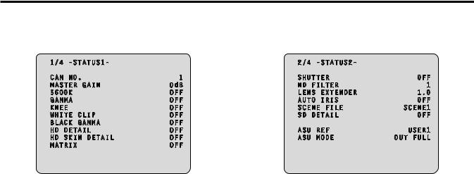
1/4 -STATUS1- |
|
CAM NO. |
1 |
MASTER GAIN |
0dB |
5600K |
OFF |
GAMMA |
OFF |
KNEE |
OFF |
WHITE CLIP |
OFF |
BLACK GAMMA |
OFF |
HD DETAIL |
OFF |
HD SKIN DETAIL |
OFF |
MATRIX |
OFF |
zzStatus displays (page 2 of 4)
From the status displays (page 1 of 4) screen, press the CHARA button of the ROP to display the second page..
2/4 -STATUS2- |
|
|
SHUTTER |
OFF |
|
ND |
FILTER |
1 |
LENS EXTENDER |
1.0 |
|
AUTO IRIS |
OFF |
|
SCENE FILE |
SCENE1 |
|
SD |
DETAIL |
OFF |
ASU |
REF |
USER1 |
ASU |
MODE |
OUT FULL |
Item |
Display |
Remarks |
|
range |
|
|
|
|
CAM No.. |
1 |
The camera number is displayed here.. |
|
│ |
|
|
19 |
|
|
|
|
MASTER GAIN |
Setting |
The master gain value is displayed |
|
values on |
here.. |
|
camera |
zzFor the setting values, refer to the |
|
|
Operating Instructions for the camera.. |
|
|
|
5600K |
OFF |
The status of the 5600K switch is |
|
ON |
displayed here.. |
|
|
OFF: 3200K, ON: 5600K |
GAMMA |
OFF |
The status of the gamma correction is |
|
ON |
displayed here.. |
|
|
|
KNEE |
OFF |
The status of the knee function is |
|
ON |
displayed here.. |
|
|
zzThis function attenuates those parts |
|
|
that have exceeded the prescribed |
|
|
level (knee point) of the video signals |
|
|
to minimize saturation.. |
|
|
|
WHITE CLIP |
OFF |
The status of the white clip function is |
|
ON |
displayed here.. |
|
|
|
BLACK GAMMA |
OFF |
The status of the black gamma function |
|
ON |
is displayed here.. |
|
|
zzThis function changes the |
|
|
amplification rate of the video signals |
|
|
in the low-brightness areas.. |
|
|
|
HD DETAIL |
OFF |
The status of the detail function for the |
|
ON |
HD signals is displayed here.. |
|
|
zzThis function (detail enhancer) |
|
|
enhances (makes sharper or softer) |
|
|
the detail image quality of the video |
|
|
output signals.. |
|
|
|
HD SKIN DETAIL |
OFF |
The status of the skin tone detail |
|
ON |
function for the HD signals is displayed |
|
|
here.. |
|
|
zzThis function minimizes or |
|
|
emphasizes the detail components |
|
|
applied to the skin tone.. |
|
|
|
MATRIX |
OFF |
The status of the matrix function is |
|
ON |
displayed here.. |
|
|
zzThis function compensates the |
|
|
saturation and hue.. |
|
|
|
Item |
Display |
Remarks |
|
range |
|
|
|
|
SHUTTER |
Setting |
The speed of the electronic shutter is |
|
values on |
displayed here.. |
|
camera |
zzFor the setting values, refer to the |
|
|
Operating Instructions for the camera.. |
|
|
|
ND FILTER |
1 |
The names of the ND filters are |
|
│ |
displayed here.. |
|
4 |
The names (each consisting of 4 |
|
|
characters) correspond to filter 1, 2, 3 |
|
|
and 4.. |
|
|
zzDisplayed as the filter names are the |
|
|
names that were set using the unit’s |
|
|
menu.. |
|
|
|
LENS |
1..0 |
The magnification of the lens extender |
EXTENDER |
2..0 |
is displayed here.. |
|
|
|
AUTO IRIS |
OFF |
The status of the auto IRIS function is |
|
ON |
displayed here.. |
|
|
|
SCENE FILE |
SCENE1 |
The selected scene file is displayed |
|
│ |
here.. |
|
SCENE4 |
|
|
OFF |
|
|
|
|
SD DETAIL |
OFF |
The status of the detail function for the |
|
ON |
SD signals is displayed here.. |
|
|
|
ASU REF |
USER1 |
The reference file used during auto |
|
USER2 |
setup is displayed here.. |
|
USER3 |
|
|
FACTORY |
|
|
|
|
ASU MODE |
OUT FULL |
The auto setup mode is displayed here.. |
|
OUT EASY |
|
|
|
|
5

Picture monitor (PM) displays (Continued)
zzStatus displays (page 3 of 4)
From the status displays (page 2 of 4) screen, press the CHARA button of the ROP to display the third page..
3/4 -STATUS3- |
|
|
||
DOWNCONVERT |
MODE |
|
SC |
|
UPCONVERT MODE |
|
SC |
||
RETURN1 |
|
HD |
SDI1 |
|
RETURN2 |
|
HD |
SDI2 |
|
RETURN3 |
|
HD |
SDI1 |
|
RETURN4 |
|
HD |
SDI2 |
|
SDI RETURN1 |
|
|
HD |
|
SDI RETURN2 |
|
|
HD |
|
SDI OUTPUT1&2 |
|
HD |
||
SDI OUTPUT3&4 |
|
HD |
||
|
NORMAL/PM |
NORMAL |
||
COMPOSITE |
|
|
|
|
|
NORMAL/PM |
|
PM |
|
Item |
Display |
|
Remarks |
|
|
range |
|
|
|
DOWNCONVERT |
SC |
The setting information of the down- |
||
MODE |
SQ |
conversion system is displayed here.. |
||
|
LB |
|
|
|
UPCONVERT |
SC |
The setting information of the |
||
MODE |
SQ |
up-conversion system is displayed here.. |
||
|
LB |
|
|
|
RETURN1 |
HD SDI1 |
The statuses of the input format |
||
RETURN2 |
HD SDI2 |
allocations for SDI return signals 1 to 4 |
||
SD SDI1 |
are displayed here.. |
|
||
RETURN3 |
|
|||
SD SDI2 |
|
|
|
|
RETURN4 |
VBS |
|
|
|
|
|
|
|
|
SDI RETURN1 |
HD |
The format of the return signal to be |
||
|
SD |
input to [HD/SD SDI 1] of the RETURN |
||
|
|
IN connectors is displayed here.. |
||
SDI RETURN2 |
HD |
The format of the return signal to be |
||
|
SD |
input to [HD/SD SDI 2] of the RETURN |
||
|
|
IN connectors is displayed here.. |
||
SDI OUTPUT1&2 |
HD |
The format of the signals to be output |
||
|
SD |
from [1] and [2] of the HD/SD SDI OUT |
||
|
|
connectors is displayed here.. |
||
SDI OUTPUT3&4 |
HD |
The format of the signals to be output |
||
|
SD |
from [3/PM] and [4/PM] of the HD/SD |
||
|
|
SDI OUT connectors is displayed here.. |
||
SDI OUTPUT3&4 |
NORMAL |
The setting information for output from |
||
NORMAL/PM |
PM |
[3/PM] and [4/PM] of the HD/SD SDI |
||
|
|
OUT connectors is displayed here.. |
||
COMPOSITE |
NORMAL |
The signal to be output from [OUT/PM] |
||
NORMAL/PM |
PM |
of the VBS connectors is displayed |
||
|
|
here.. |
|
|
zzStatus displays (page 4 of 4)
From the status displays (page 3 of 4) screen, press the CHARA button of the ROP to display the fourth page..
4/4 -STATUS4-
HOURS CCU |
H |
CABLE OPEN
CABLE SHORT
CAM RECEIVE LEVEL
CCU RECEIVE LEVEL
VERSION 1.00-00-0.00
Item |
Display |
Remarks |
||||||||||
|
|
range |
|
|||||||||
|
|
|
|
|
|
|
|
|
|
|
|
|
HOURS CCU |
|
|
|
|
|
|
—— |
The unit’s cumulative operation time is |
||||
|
|
|
|
|
|
|
|
|
|
|
|
displayed here.. |
|
|
|
|
|
|
|
|
|
|
|
|
|
CABLE OPEN |
|
|
|
|
|
|
—— |
This item flashes when the optical fiber |
||||
|
|
|
|
|
|
|
|
|
|
|
|
multi cable is not connected.. |
|
|
|
|
|
|
|
|
|
|
|
|
|
CABLE SHORT |
|
|
|
|
|
|
—— |
This item flashes when the optical fiber |
||||
|
|
|
|
|
|
|
|
|
|
|
|
multi cable is short-circuited.. |
|
|
|
|
|
|
|
|
|
|
|
|
|
CAM RECEIVE |
|
|
|
|
|
|
|
|
|
|
|
The level of the optical signals received |
|
|
|
|
|
|
|
|
|
|
|
||
LEVEL |
|
|
|
|
|
|
|
|
|
│ |
by the camera is displayed in 5 |
|
|
|
|
|
|
|
|
|
|
|
|
|
gradations.. |
|
|
|
|
|
|
|
|
|
|
|
|
|
|
|
|
|
|
|
|
|
|
|
|
|
|
CCU RECEIVE |
|
|
|
|
|
|
|
|
|
|
|
The level of the optical signals received |
|
|
|
|
|
|
|
|
|
|
|
||
LEVEL |
|
|
|
|
|
|
|
|
|
│ |
by the unit is displayed in 5 gradations.. |
|
|
|
|
|
|
|
|
|
|
|
|
|
|
|
|
|
|
|
|
|
|
|
|
|
|
|
|
|
|
|
|
|
|
|
|
|
|
|
|
VERSION |
|
|
|
|
|
|
—— |
The unit’s software version is displayed |
||||
|
|
|
|
|
|
|
|
|
|
|
|
here.. |
|
|
|
|
|
|
|
|
|
|
|
|
|
6
Picture monitor (PM) displays (Continued)
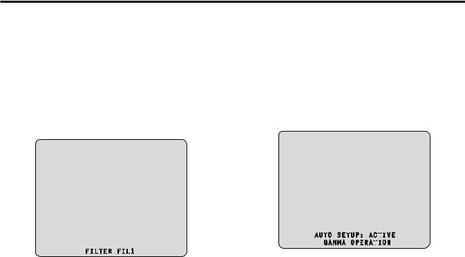
zzOperation displays (manual)
The operation displays appear at the bottom of the screen for 4 seconds when any of the following operations have been performed with the operation panel of the ROP..
zz“MASTER GAIN” is changed zz“SHUTTER” is changed zz“LENS EXT” is changed zz“FILTER” is changed zz“SCENE FILE” is changed zz“REF LOAD” is changed
The display time can be changed from “MAINTENANCE” menu → “PM OPERATION STATUS” → “STATUS DISP TIME”..
FILTER FIL1
Item |
Display |
Remarks |
|
range |
|
MASTER GAIN |
Setting |
The master gain value is displayed |
|
values on |
here.. |
|
camera |
(in 3 dB increments) |
|
|
zzFor the setting values, refer to the |
|
|
Operating Instructions for the camera.. |
|
|
|
SHUTTER |
Setting |
The speed of the electronic shutter is |
|
values on |
displayed here.. |
|
camera |
zzFor the setting values, refer to the |
|
|
Operating Instructions for the camera.. |
|
|
|
LENS EXT |
1..0 |
The magnification of the lens extender |
|
2..0 |
is displayed here.. |
|
|
zzWhen the magnification of the |
|
|
lens extender is set to 2×, “2..0” is |
|
|
displayed.. |
|
|
Otherwise, “1..0” is displayed.. |
|
|
|
FILTER |
4 characters |
The name of the ND filter is displayed |
|
|
here.. |
|
|
|
SCENE FILE |
SCENE1 |
This indicates the scene file name.. |
|
│ |
|
|
SCENE4 |
|
|
OFF |
|
|
|
|
REF LOAD |
FACTORY |
This indicates the reference file that was |
|
USER1 |
loaded using the SCENE command.. |
|
USER2 |
|
|
USER3 |
|
|
|
|
zzOperation displays (AUTO)
If the AWB function, ABB function, or AUTO SETUP function has been activated when a menu is not displayed on the picture monitor, information on the operation performed appears at the bottom of the screen..
When the AUTO SETUP operations are displayed, they will remain displayed until the operations are completed..
The display is cleared 4 seconds after the operations are completed.. If the operations cannot be completed, they will remain displayed until the NG (error) items of the AUTO function are released..
The display time can be changed from “MAINTENANCE” menu → “PM OPERATION STATUS” → “STATUS DISP TIME”..
|
|
|
|
|
|
|
|
|
|
|
|
|
AUTO SETUP: ACT |
IVE |
|||||||||
|
GAMMA |
OPERAT |
|
|
ION |
|
|||||
|
|
|
|
||||||||
|
|
|
|
|
|||||||
|
Display description: |
|
|||||||||
Item |
Appears on two lines at the bottom of the screen.. |
||||||||||
|
|
|
|
|
|
|
|
|
|
||
Top line: status |
|
||||||||||
|
|
||||||||||
|
Bottom line: Detailed information |
||||||||||
|
|
|
|
|
|
|
|
|
|
|
|
ABB START |
ABB: ACTIVE |
|
|
|
|
|
|
|
|
||
|
|
|
|
|
|
|
|
|
|
|
|
|
(None) |
|
|
|
|
|
|
|
|
||
|
|
|
|
|
|
|
|
|
|
|
|
AWB START |
AWB: ACTIVE |
|
|
|
|
|
|
|
|
||
|
|
|
|
|
|
|
|
|
|
|
|
|
(None) |
|
|
|
|
|
|
|
|
||
|
|
|
|
|
|
||||||
AUTO OK |
ABB: OK |
|
AWB: OK |
AUTO SETUP: OK |
|||||||
(Common to |
|
|
|
|
|
|
|
|
|
|
|
(None) |
|
|
|
|
|
|
|
|
|||
ABB, AWB, and |
|
|
|
|
|
|
|
|
|||
AUTO SETUP) |
|
|
|
|
|
|
|
|
|
|
|
|
|
|
|
||||||||
AUTO NG1*1 |
ABB: NG |
|
AWB: NG |
||||||||
(Only for ABB |
|
|
|
|
|
|
|
|
|
|
|
Detailed information of the NG (error) message is |
|||||||||||
and AWB) |
|||||||||||
displayed here*1.. |
|
||||||||||
|
|
||||||||||
AUTO SETUP |
AUTO SETUP: ACTIVE |
|
|||||||||
START*2 |
|
|
|
|
|
|
|
|
|
|
|
Detailed information is displayed here*2.. |
|||||||||||
|
|||||||||||
AUTO NG2*3 |
AUTO SETUP: NG |
|
|||||||||
(Only for AUTO |
|
||||||||||
Detailed information of the NG (error) message is |
|||||||||||
SETUP) |
displayed here*3.. |
|
|||||||||
|
|
||||||||||
AUTO BREAK |
ABB: BREAK |
|
AWB: BREAK |
AUTO SETUP: BREAK |
|||||||
(Common to |
|
|
|
|
|
|
|
|
|
|
|
(None) |
|
|
|
|
|
|
|
|
|||
ABB, AWB and |
|
|
|
|
|
|
|
|
|||
AUTO SETUP) |
|
|
|
|
|
|
|
|
|
|
|
|
|
|
|||||||||
AUTO READY |
AUTO SETUP: READY |
|
|||||||||
(Only for AUTO |
|
|
|
|
|
|
|
|
|
||
(None) |
|
|
|
|
|
|
|
|
|||
SETUP) |
|
|
|
|
|
|
|
|
|
|
|
7

Picture monitor (PM) displays (Continued)
*1: [AUTO NG1 detailed information]
The AUTO NG1 detailed information is displayed flashing on the screen..
Rch OUT RANGE
Gch OUT RANGE
Bch OUT RANGE
AWB LOW LIGHT
AWB HIGH LIGHT
*2: [AUTO SETUP operation information]
The AUTO SETUP operation information is displayed on the screen..
B..SHD OPERATION
FLARE OPERATION
ABB OPERATION
AWB OPERATION
*3: [AUTO NG2 detailed information]
The AUTO NG2 detailed information is displayed flashing on the screen..
ABB Gch OUT RANGE
ABB Bch OUT RANGE
ABB Rch OUT RANGE
B..SHD Gch OUT RANGE
B..SHD Bch OUT RANGE
B..SHD Rch OUT RANGE
FLARE Gch OUT RANGE
FLARE Bch OUT RANGE
FLARE Rch OUT RANGE
AWB Gch OUT RANGE
AWB Bch OUT RANGE
AWB Rch OUT RANGE
NOT RUNNING
ILLEGAL MODE(CINEGAMMA)
NOT RUNNING
ILLEGAL MODE(D..EXT)
NOT RUNNING
ILLEGAL MODE(SCANREVERSE)
NOT RUNNING
ILLEGAL MODE(BAR)
NOT RUNNING
ILLEGAL MODE(TESTSAW)
zzContrast automatic adjustment display
This appears when contrast automatic adjustment (DRS SWITCH) is set to ON by ROP operation..
<DRS ON>
zzFor details on contrast automatic adjustment, refer to the Operating Instructions for the ROP..
8

Menu operations
While viewing the menu screen of the picture monitor, operate the MENU button and SELECT dial on the front panel..
MENU button
SELECT dial
Displaying and hiding the menus
1.Hold down the MENU button
The menu screen appears and the MENU button lights.. “TOP MENU” appears first..
zzIf the MENU button is held down when the menu is displayed, the menu closes and the MENU button turns off..
Hold down the MENU button 
 Hold down the MENU button
TOP MENU
OPERATION
MAINTENANCE
Basic menu operations
Selecting a menu
1.Press the SELECT dial
Move the cursor to the desired item (OPERATION or MAINTENANCE) on the “TOP MENU” screen, and then press the SELECT dial to display the menu screen one level below the selected item..
zzWhen the SELECT dial is turned clockwise, the cursor moves down; conversely, when it is turned counterclockwise, the cursor moves up..
TOP MENU
 OPERATION
2.Turn the SELECT dial to move the cursor to the menu item you want to set, and then press the SELECT dial..
OPERATION
 SETTING1
SETTING2
HD/SD
 PHASE
PHASE
BAR ID
The setting screen one level below the selected menu item appears..
|
SETTING1 |
|
CCU |
MODE |
1080/59.94i |
SDI RETURN1 |
HD |
|
SDI RETURN2 |
HD |
|
SDI OUTPUT1&2 |
HD |
|
SDI |
OUTPUT3&4 |
HD |
zzMoving the cursor to the menu title and then pressing the SELECT dial redisplays “TOP MENU”..
TOP MENU
 OPERATION
9

Menu operations (Continued)
Changing the setting value of a setting item
A number of items and the set values are displayed on the setting screen at the lowest level..
1.Turn the SELECT dial to move the cursor to the menu item you want to set, and then press the SELECT dial..
The setting value of the selected menu item starts flashing and you can change it..
|
SETTING1 |
|
CCU |
MODE |
1080/59.94i |
SDI RETURN1 |
HD |
|
SDI RETURN2 |
HD |
|
SDI OUTPUT1&2 |
HD |
|
SDI |
OUTPUT3&4 |
HD |
Menu items with multiple setting items on one line and text input menu items
1.Turn the SELECT dial to move the cursor to the menu item you want to set, and then press the SELECT dial..
The cursor becomes “” and you can use the SELECT dial to move the cursor to a setting item in the selected menu item..
|
BAR ID |
|
BAR |
ID SWITCH |
OFF |
BRIGHTNESS |
100% |
|
ID1 |
POSITION |
V:00 H:00 |
2.Turn the SELECT dial to change the value, and then press the SELECT dial..
Turning the SELECT dial changes the setting value and pressing the SELECT dial confirms the setting value..
|
SETTING1 |
|
CCU |
MODE |
1080/59.94i |
SDI RETURN1 |
SD |
|
SDI RETURN2 |
HD |
|
SDI OUTPUT1&2 |
HD |
|
SDI |
OUTPUT3&4 |
HD |
Once the setting value has been confirmed, the flashing stops, and the cursor can be moved from one menu to another..
In some cases, the setting is reflected when the setting value is changed in the flashing state; in other cases, it is reflected when the SELECT dial is pressed to confirm the setting value..
2.Turn the SELECT dial to move the cursor to the item you want to set, and then press the SELECT dial..
The setting value of the selected item starts flashing and you can change it..
|
BAR ID |
|
BAR |
ID SWITCH |
OFF |
BRIGHTNESS |
100% |
|
ID1 |
POSITION |
V:00 H:00 |
3.Turn the SELECT dial to change the value, and then press the SELECT dial..
Turning the SELECT dial changes the setting value (or characters), and pressing the SELECT dial confirms the setting value (or characters)..
|
BAR ID |
|
BAR |
ID SWITCH |
OFF |
BRIGHTNESS |
100% |
|
ID1 |
POSITION |
V:02 H:00 |
When the setting value is confirmed and the flashing stops, you can move the cursor..
If you press the SELECT dial while the cursor is on the left of a menu item, the cursor becomes “” and you can select the menu item..
|
BAR ID |
|
BAR |
ID SWITCH |
OFF |
BRIGHTNESS |
100% |
|
ID1 |
POSITION |
V:02 H:03 |
10
Setting menu items
TOP MENU
This is the first screen displayed when you hold down the MENU button.. Select one of the menus..
TOP MENU
OPERATION
MAINTENANCE
zzOPERATION
Select this to open the OPERATION menu screen..
zzMAINTENANCE
Select this to open the MAINTENANCE menu screen..
OPERATION menu
This is the selection screen for the OPERATION menu..
Moving the cursor to the “OPERATION” menu title and then pressing the SELECT dial redisplays “TOP MENU”..
OPERATION
SETTING1
SETTING2
HD/SD
 PHASE
PHASE
BAR ID
INCOM/MIC
zzSETTING1
Select this to display the SETTING1 screen..
zzSETTING2
Select this to display the SETTING2 screen..
zzHD/SD PHASE
Select this to display the HD/SD PHASE screen..
zzBAR ID
Select this to display the BAR ID screen..
zzINCOM/MIC
Select this to display the INCOM/MIC screen..
zzSETTING1 Screen
This is the selection screen for the SETTING1 menu..
Moving the cursor to the “SETTING1” menu title and then pressing the SELECT dial redisplays the OPERATION menu one level up..
SETTING1 |
|
CCU MODE |
1080/59.94i |
SDI RETURN1 |
HD |
SDI RETURN2 |
HD |
SDI OUTPUT1&2 |
HD |
SDI OUTPUT3&4 |
HD |
NORMAL/PM |
PM |
COMPOSITE |
|
NORMAL/PM |
PM |
indicates the factory default setting..
Item |
Setting |
Remarks |
|
value |
|||
|
|
||
|
|
|
|
CCU MODE |
59..94 Hz: |
Set the format of the signal to be output |
|
|
1080/59..94i |
from the unit.. |
|
|
1080/50i |
|
|
|
|
|
|
|
50 Hz: |
|
|
|
1080/59..94i |
|
|
|
1080/50i |
|
|
|
|
|
|
SDI RETURN1 |
HD |
Set the format of the return signal to be |
|
|
SD |
input to [HD/SD SDI 1] of the RETURN |
|
|
|
IN connectors.. |
|
|
|
|
|
SDI RETURN2 |
HD |
Set the format of the return signal to be |
|
|
SD |
input to [HD/SD SDI 2] of the RETURN |
|
|
|
IN connectors.. |
|
|
|
|
|
SDI OUTPUT1&2 |
HD |
Set the format of the signals to be |
|
|
SD |
output from [1] and [2] of the HD/SD |
|
|
|
SDI OUT connectors.. |
|
|
|
|
|
SDI OUTPUT3&4 |
HD |
Set the format of the signals to be |
|
|
SD |
output from [3/PM] and [4/PM] of the |
|
|
|
HD/SD SDI OUT connectors.. |
|
|
|
|
|
SDI OUTPUT3&4 |
NORMAL |
Set the signal to be output from [3/PM] |
|
NORMAL/PM |
PM |
and [4/PM] of the HD/SD SDI OUT |
|
|
|
connectors.. |
|
|
|
NORMAL: |
|
|
|
Output the main line images.. |
|
|
|
PM: |
|
|
|
Output the picture monitor images.. |
|
|
|
|
|
COMPOSITE |
NORMAL |
Set the signal to be output from |
|
NORMAL/PM |
PM |
[OUT/PM] of the VBS connectors.. |
|
|
|
NORMAL: |
|
|
|
Output the main line images.. |
|
|
|
PM: |
|
|
|
Output the picture monitor images.. |
|
|
|
|
zzWhen the SDI OUTPUT3&4 NORMAL/PM item and COMPOSITE NORMAL/PM item are set to “NORMAL”, the menus and statuses will not be able to be displayed because the picture monitor images will not be output..
When one of items is set to “NORMAL”, the other one is set to “PM” as both of the items cannot be set to “NORMAL”..
11

Setting menu items (Continued)
zzSETTING2 Screen
This is the selection screen for the SETTING2 menu..
Moving the cursor to the “SETTING2” menu title and then pressing the SELECT dial redisplays the OPERATION menu one level up..
|
SETTING2 |
|
|
FS |
DELAY |
NORMAL |
|
HD |
BAR |
SELECT |
ARIB |
|
BAR |
LPF |
7TAP |
|
BAR |
USER1 |
75%WHITE |
|
BAR |
USER2 |
0%BLACK |
SETUP 7.5% |
OFF |
||
PATHO |
|
OFF |
|
indicates the factory default setting..
Item |
Setting |
Remarks |
|
value |
|||
|
|
||
|
|
|
|
FS DELAY |
NORMAL |
Select the delay mode for the HD return |
|
|
SHORT |
signals.. |
|
|
|
NORMAL: |
|
|
|
Matches return signal input that does |
|
|
|
not match the sync phase to the |
|
|
|
phase of the camera by delaying it by |
|
|
|
1 frame.. |
|
|
|
SHORT: |
|
|
|
Sets the shortest delay.. (5 H) |
|
|
|
However, if the following conditions |
|
|
|
are not met, it is delayed by |
|
|
|
1 frame + 5H.. |
|
|
|
zzHD signal |
|
|
|
zzThe SD-HD V item in the HD/SD |
|
|
|
PHASE screen is “ADVANCE” or |
|
|
|
“0H_SD_DLAY” |
|
|
|
zzWhen output from this unit is used |
|
|
|
as the return signal, the delay is |
|
|
|
less than 3H |
|
|
|
|
|
HD BAR SELECT |
FULL |
Select the color bar signals to be output |
|
|
BARS-1 |
from the HD/SD SDI OUT connectors |
|
|
ARIB |
and VBS connector when “BAR” has |
|
|
BARS-2 |
been selected on the operation panel |
|
|
BARS-3 |
of the ROP.. |
|
|
BARS-4 |
When they are output in VBS or SD |
|
|
BARS-5 |
format, color bars in HD format are |
|
|
BARS-6 |
output in the mode specified with |
|
|
|
DOWNCONVERT MODE*.. |
|
|
|
FULL: |
|
|
|
75 % full field color bar |
|
|
|
BARS-1: |
|
|
|
Color bar based on the SMPTE |
|
|
|
standard |
|
|
|
ARIB: |
|
|
|
ARIB multi-format color bar |
|
|
|
BARS-2: |
|
|
|
Color bar based on the EIAJ standard |
|
|
|
BARS-3: |
|
|
|
Split field color bar |
|
|
|
BARS-4: |
|
|
|
75 % full field color bar placed in an |
|
|
|
area with a 4:3 aspect ratio.. |
|
|
|
(Displayed 40 % gray outside the |
|
|
|
area..) |
|
|
|
BARS-5: |
|
|
|
Color bar based on the SMPTE |
|
|
|
standard that is placed in an area |
|
|
|
with a 4:3 aspect ratio.. |
|
|
|
(Displayed 40 % gray outside the |
|
|
|
area..) |
|
|
|
BARS-6: |
|
|
|
Color bar based on the EIAJ standard |
|
|
|
that is placed in an area with a 4:3 |
|
|
|
aspect ratio.. |
|
|
|
(Displayed 40 % gray outside the |
|
|
|
area..) |
|
|
|
|
Item |
Setting |
Remarks |
|
value |
|||
|
|
||
|
|
|
|
BAR LPF |
OFF |
Select the filter through which to pass |
|
|
3TAP |
the color bar signals to be output |
|
|
5TAP |
from the HD/SD SDI OUT connectors |
|
|
7TAP |
when BAR has been selected on the |
|
|
9TAP |
operation panel of the ROP.. |
|
|
|
zzA higher TAP value will ensure a |
|
|
|
smooth rise and fall of the waveforms |
|
|
|
and reduce both the overshoot and |
|
|
|
undershoot.. |
|
|
|
|
|
BAR USER1 |
75%WHITE |
Set user range 1 for when ARIB has |
|
|
100%WHITE |
been selected as the HD BAR SELECT |
|
|
+I_SIGNAL |
setting.. |
|
|
–I_SIGNAL |
This can be set when “ARIB” is selected |
|
|
|
for the HD BAR SELECT item.. |
|
|
|
In the case of another setting, “——” |
|
|
|
is displayed and a setting cannot be |
|
|
|
selected.. |
|
|
|
|
|
BAR USER2 |
0%BLACK |
Set user range 2 for when ARIB has |
|
|
+Q_SIGNAL |
been selected as the HD BAR SELECT |
|
|
|
setting.. |
|
|
|
This can be set when “ARIB” is selected |
|
|
|
for the HD BAR SELECT item.. |
|
|
|
In the case of another setting, “——” |
|
|
|
is displayed and a setting cannot be |
|
|
|
selected.. |
|
|
|
|
|
SETUP 7..5% |
ON |
Select whether to add the setup 7..5 % |
|
|
OFF |
level to the SD signals to be output from |
|
|
|
[OUT/PM] of the VBS connectors.. |
|
|
|
|
|
PATHO |
ON |
Select ON/OFF for the pathological |
|
|
OFF |
signals.. |
|
|
|
|
*: The DOWNCONVERT MODE setting can be configured by operating the REMOTE OPERATION menu with the ROP..
For details, refer to Operating Instructions <Operations and Settings> of AK-HRP200..
12
 Loading...