


SJDE-ANA-OY
Table of contents
 Loading...
Manual No.
TOEP-C71080603-01-OY
OMRON YASKAWA Motion Control B.V.
JUNMA SERIES SERVO DRIVE
Mechatrolink-II communications type
Model: SJDE- ANA-OY
USER´ S MANUAL

Copyright © 2006 YASKAWA ELECTRIC CORPORATION
All rights reserved. No part of this publication may be reproduced, stored in a retrieval
system, or transmitted, in any form, or by any means, mechanical, electronic, photocopying, recording, or otherwise, without the prior written permission of Yaskawa. No
patent liability is assumed with respect to the use of the information contained herein.
Moreover, because Yaskawa is constantly striving to improve its high-quality products,
the information contained in this manual is subject to change without notice. Every precaution has been taken in the preparation of this manual. Nevertheless, Yaskawa
assumes no responsibility for errors or omissions. Neither is any liability assumed for
damages resulting from the use of the information contained in this publication.
Introduction
This instruction manual describes the JUNMA series AC SERVOPACKs. To properly use the JUNMA
series AC SERVOPACKs, read these instructions thoroughly and retain for easy reference for inspections,
maintenance, and so on. Make sure that the end user receives this manual.
Related Manuals
Refer to the following manuals as required.
Manual Name Manual Number
JUNMA series AC SERVOMOTOR
INSTRUCTIONS
TOMPC23026100
or
TOEPC23026101
Safety Information
The following conventions are used to indicate precautions in this manual. Failure to heed these precautions can result in serious or possibly even fatal injury or damage to the products or to related equipment
and systems.
WARNING
CAUTION
PROHIBITED
MANDATORY
Indicates precautions that, if not heeded, could possibly result in loss of life or serious injury.
Indicates precautions that, if not heeded, could result in relatively serious or minor
injury, damage to the product, or faulty operation.
In some situations, the precautions indicated could have serious consequences if
not heeded.
Indicates prohibited actions that must not be performed. For example, this symbol
would be used as follows to indicate that fire is prohibited: .
Indicates compulsory actions that must be performed. For example, this symbol
would be used as follows to indicate that grounding is compulsory: .
Visual Aids
The following aids are used to indicate certain types of information for easier reference.
• Indicates important information that should be memorized, including precautions
IMPORTANT
INFOINFO
such as alarm displays to avoid damaging the devices.
• Indicates supplemental information.
Trademarks
MECHATROLINK is a trademark of the MECHATROLINK Members Association.
1

Notes for Safe Operation
Read these instructions thoroughly before checking products on delivery, storage and transportation,
installation, wiring, operation and inspection, and disposal of the AC SERVOPACK.
WARNING
• Be sure to correctly connect the SERVOPACK connectors.
Incorrect wiring may result in electric shock, fire, or damage to the equipment. For the wir-
ing method, refer to 3.4 Main Circuit Wiring.
• Use the emergency stop signal input E-STP to forcibly turn OFF the servo from an external
sequence, such as host controller, at occurrence of servo alarm or system emergency stop.
The residual voltage rotates the servomotor for a few seconds after the power supply has
been turned OFF, and may result in injury or damage to the equipment. Be sure to completely stop the motor by turning OFF the servo using the emergency stop.
• Configure the circuit’s power supply to be automatically cut off if E-STP signal is OFF at
occurrence of emergency stop
The residual voltage rotates the servomotor for a few seconds after the power supply has
been turned OFF, and may result in injury or damage to the equipment. Be sure to completely stop the motor by turning OFF the servo using the emergency stop.
Position information is not stored in the SERVOPACK, so this information will be lost if the
power supply is turned OFF. This information cannot be read again if the power supply is
turned OFF.
• Never touch any rotating motor parts while the motor is running.
Failure to observe this warning may result in injury.
• Before starting operation with a machine connected, make sure that an emergency stop can
be applied at any time. Also, configure the circuit’s power supply to be automatically cut off if
E-STP signal is OFF at occurrence of emergency stop.
Failure to observe this warning may result in injury.
• Never touch the inside of the SERVOPACK.
Failure to observe this warning may result in electric shock.
• Do not touch terminals for five minutes after the power is turned OFF.
Residual voltage may cause electric shock.
• Follow the procedures and instructions for trial operation precisely as described in this man-
ual.
Malfunctions that occur after the servomotor is connected to the equipment not only damage the equipment, but may also cause an accident resulting in death or injury.
• Do not remove cables, connectors, or optional items while the power is ON.
Failure to observe this warning may result in electric shock.
• Installation, wiring, advice on inspection and malfunction must be performed only by autho-
rized personnel.
Failure to observe this warning may result in fire, electric shock, or injury.
• Do not damage, press, exert excessive force or place heavy objects on the cables or the
cables between other objects where they might be pinched.
Failure to observe this warning may result in electric shock, stopping operation of the product, or burning.
2
WARNING
• Provide an appropriate stopping device on the machine side to ensure safety.
A holding brake for a servomotor with brake is not a stopping device for ensuring safety.
Failure to observe this warning may result in injury.
• Do not come close to the machine immediately after resetting momentary power loss to
avoid an unexpected restart.
Take appropriate measures to ensure safety against an unexpected restart. Failure to
observe this warning may result in injury.
• Never modify the product.
Failure to observe this warning may result in injury or damage to the product.
• Be sure to correctly ground the SERVOPACK and the servomotor.
• Connect the SERVOPACK’s ground terminal to electrical codes (ground resistance: 100 Ω
or less).
Improper grounding may result in electric shock.
Checking on Delivery
CAUTION
• Always use the servomotor and SERVOPACK in one of the specified combinations.
Failure to observe this caution may result in fire or malfunction.
Storage and Transportation
CAUTION
• Do not store or install the product in the following places.
Failure to observe this caution may result in damage to the product.
• Locations subject to direct sunlight.
• Locations subject to temperatures outside the range specified in the storage or installation temperature conditions.
• Locations subject to humidity outside the range specified in the storage or installation
humidity conditions.
• Locations subject to condensation as the result of extreme changes in temperature.
• Locations subject to corrosive or flammable gases.
• Locations subject to dust, salts, or iron dust.
• Locations subject to exposure to water, oil, or chemicals.
• Locations subject to shock or vibration.
• Do not hold the product by the cables or motor shaft while transporting it.
Failure to observe this caution may result in injury or malfunction.
• Do not place any load exceeding the limit specified on the packing box.
Failure to observe this caution may result in injury or malfunction.
3
Installation
CAUTION
• Make sure to follow the conditions on 2.1 Installation Conditions.
Failure to observe this caution may result in electric shock, fire, or SERVOPACK’s malfunc-
tion.
• Do not step on or place a heavy object on the product.
Failure to observe this caution may result in injury.
• Do not cover the inlet or outlet parts of the SERVOPACK and prevent any foreign objects,
such as metallic fragment, or combustibles from entering the product.
Failure to observe this caution may cause internal elements to deteriorate resulting in malfunction or fire.
• Be sure to install the product in the correct direction.
Failure to observe this caution may result in malfunction.
• Provide the specified clearances between the SERVOPACK and the control panel or with
other devices.
Failure to observe this caution may result in fire or malfunction.
• SERVOPACK and servomotor are precision equipment. Do not apply any strong impact.
Failure to observe this caution may result in malfunction.
4
Wiring
WARNING
• Be sure to correctly ground the SERVOPACK and the servomotor.
• Wiring must be performed by an authorized person qualified in electrical work.
• When using the servomotor for a vertical axis, install safety devices to prevent workpieces
from falling off because of alarms. Workpiece’s falling off may result in injury or malfunction.
• Configure the interlock circuit so that the system is interlocked to avoid injury whenever the
protective cover on the machine is opened or closed.
• Use the emergency stop signal input E-STP to forcibly turn OFF the servo from an external
sequence, such as host controller, at occurrence of servo alarm or system emergency stop.
The residual voltage rotates the servomotor for a few seconds after the power supply has
been turned OFF, and may result in injury or damage to the equipment. Be sure to completely stop the motor by turning OFF the servo using the emergency stop.
• When executing the JOG operation and the home position search operation using CX-Drive,
the E-STP signal will be ignored. Alternative measures must be taken in case an emergency stop is needed.
• Configure the circuit’s power supply to be automatically cut off if E-STP signal is OFF at
occurrence of emergency stop.
The residual voltage rotates the servomotor for a few seconds after the power supply has
been turned OFF, and may result in injury or damage to the equipment.
Position information is not stored in the SERVOPACK, so this information will be lost if the
power supply is turned OFF. This information cannot be read again if the power supply is
turned OFF.
• When executing JOG operation and the home position search operation using CX-Drive, the
P-OT and N-OT signals will be ignored. Alternative measures must be taken in case of
overtravel.
5
CAUTION
• Do not connect a three-phase power supply to the U, V, or W output terminals.
Failure to observe this caution may result in injury or fire.
• Securely connect the power supply terminals, regenerative unit connection terminal, and
motor main circuit cable terminals.
Failure to observe this caution may result in fire.
• Do not bundle or run power and signal lines together in the same duct. Keep power and sig-
nal lines separated by at least 300 mm. (11.81 in).
Failure to observe this caution may result in malfunction.
• Use twisted-pair shielded wires or multi-core twisted pair shielded wires for I/O signal cable
and encoder cable.
The maximum length is 3 m (118.11 in) for I/O signal cable and is 20 m (787.40 in) for
encoder cable.
• Do not touch the power terminals for five minutes after turning the power supply LED (PWR)
are OFF because high voltage may still remain in the SERVOPACK.
• Avoid frequently turning power ON and OFF. Do not turn power ON or OFF more than once
per minute.
Since the SERVOPACK has a capacitor in the power supply, a high charging current flows
when power is turned ON. Frequently turning power ON and OFF causes main power
devices such as capacitors and fuses to deteriorate, resulting in unexpected problems.
• Observe the following precautions when wiring connector for power supply/regenerative
unit.
• Remove the connector for power supply/regenerative unit from the SERVOPACK prior to
wiring.
• Insert only one wire per terminal on the connector for power supply/regenerative unit.
• Make sure that the core wire is not electrically shorted to adjacent core wires.
• Be sure to wire correctly and securely.
Failure to observe this caution may result in motor overrun, injury, or malfunction.
• Always use the specified power supply voltage of single-phase 200 V to 230 V without con-
necting directly to the power supply of 400 V.
The SERVOPACK will be destroyed.
• Take appropriate measures to ensure that the input power supply is supplied within the
specified voltage fluctuation range.
An incorrect power supply may result in damage to the product.
• Install external breakers or other safety devices against short-circuit in external wiring.
Failure to observe this caution may result in fire.
• Take appropriate and sufficient countermeasures for each when installing systems in the fol-
lowing locations.
Failure to observe this caution may result in damage to the product.
• Locations subject to static electricity or other forms of noise.
• Locations subject to strong electromagnetic fields and magnetic fields.
• Locations subject to possible exposure to radioactivity.
• Locations close to power supplies, including power supply lines.
• Do not reverse the polarity of the battery when wiring with regenerative unit.
Failure to observe this caution may result in damage to the product.
6
Operation
CAUTION
• Conduct trial operation on the servomotor alone with the motor shaft disconnected from
machine to avoid any unexpected accidents.
Failure to observe this caution may result in injury.
• During the JOG operation and the home position search operation using CX-Drive, the forward run prohibited (P-OT), reverse run prohibited (N-OT), and emergency stop (E-STP)
signals will be ignored. Alternative measures must be taken in case of overtravel and emergency stop.
• When using the servomotor for a vertical axis, install safety devices to prevent workpieces
from falling off because of alarms.
Workpiece’s falling off may result in injury or malfunction.
• Do not touch the SERVOPACK heat sinks, regenerative unit, or servomotor while power is
ON or soon after the power is turned OFF.
Failure to observe this caution may result in burns due to high temperatures.
• When an alarm occurs, remove the cause, turn OFF the power and ON again after confirming safety, and then resume operation.
Failure to observe this caution may result in injury.
• Do not use the holding brake of the servomotor for ordinary braking.
Failure to observe this caution may result in malfunction.
Maintenance and Inspection
CAUTION
• Do not open the SERVOPACK case for 5 minutes after the power supply indicator (PWR
LED) goes out. High voltage may remain in the SERVOPACK after the power supply has
been turned OFF.
• After turning OFF the power supply, wait 15 minutes before replacing the cooling fan.
Failure to observe this caution may result in burns because the heat sink is hot.
• Mount the cooling fan in the correct way explained in 9.3 Replacement of Cooling Fan.
Improper mounting may result in the breakdown of the SERVOPACK.
• Do not attempt to change wiring while the power is ON.
Failure to observe this caution may result in electric shock or injury.
• Do not touch the SERVOPACK heat sinks, regenerative unit, or servomotor while power is
ON or soon after the power is turned OFF.
Disposal
CAUTION
• When disposing of the products, treat them as general industrial waste.
7

General Precautions
Note the following to ensure safe application.
• The drawings presented in this manual are sometimes shown without covers or protective guards.
Always replace the cover or protective guard as specified first, and then operate the products in
accordance with the manual.
• The drawings presented in this manual are typical examples and may not match the product you
received.
• This manual is subject to change due to product improvement, specification modification, and manual improvement. When this manual is revised, the manual code is updated and the new manual is
published as a next edition.
• If the manual must be ordered due to loss or damage, inform your nearest Omron Yaskawa representative or one of the offices listed on the back of this manual.
• Omron Yaskawa will not take responsibility for the results of unauthorized modifications of this
product. Omron Yaskawa shall not be liable for any damages or troubles resulting from unauthorized modification.
8

CONTENTS
Introduction - - - - - - - - - - - - - - - - - - - - - - - - - - - - - - - - - - - - - - - - - - - - - -1
Related Manuals - - - - - - - - - - - - - - - - - - - - - - - - - - - - - - - - - - - - - - - - - -1
Safety Information - - - - - - - - - - - - - - - - - - - - - - - - - - - - - - - - - - - - - - - - -1
Visual Aids- - - - - - - - - - - - - - - - - - - - - - - - - - - - - - - - - - - - - - - - - - - - - - -1
Trademarks - - - - - - - - - - - - - - - - - - - - - - - - - - - - - - - - - - - - - - - - - - - - - -1
Notes for Safe Operation- - - - - - - - - - - - - - - - - - - - - - - - - - - - - - - - - - - - -2
1 Before Use- - - - - - - - - - - - - - - - - - - - - - - - - - - - - - - - - - - - - - - - - - - - 13
1.1 Checking Products - - - - - - - - - - - - - - - - - - - - - - - - - - - - - - - - - - - - - - - - - - - - - - - - 13
1.2 Warning Label- - - - - - - - - - - - - - - - - - - - - - - - - - - - - - - - - - - - - - - - - - - - - - - - - - - - 13
1.3 Model Designation - - - - - - - - - - - - - - - - - - - - - - - - - - - - - - - - - - - - - - - - - - - - - - - - 14
1.4 SERVOPACKs and Applicable Servomotors- - - - - - - - - - - - - - - - - - - - - - - - - - - - - - - 14
1.5 Part Names and Functions- - - - - - - - - - - - - - - - - - - - - - - - - - - - - - - - - - - - - - - - - - - 15
1.6 Applicable Standards- - - - - - - - - - - - - - - - - - - - - - - - - - - - - - - - - - - - - - - - - - - - - - - 16
1.6.1 North American Safety Standards (UL, CSA) - - - - - - - - - - - - - - - - - - - - - - - - - - - 16
1.6.2 European Directives - - - - - - - - - - - - - - - - - - - - - - - - - - - - - - - - - - - - - - - - - - - - - 16
2 Installation - - - - - - - - - - - - - - - - - - - - - - - - - - - - - - - - - - - - - - - - - - - -17
2.1 Installation Conditions - - - - - - - - - - - - - - - - - - - - - - - - - - - - - - - - - - - - - - - - - - - - - - 17
2.2 Installation Method - - - - - - - - - - - - - - - - - - - - - - - - - - - - - - - - - - - - - - - - - - - - - - - - 18
3 Wiring - - - - - - - - - - - - - - - - - - - - - - - - - - - - - - - - - - - - - - - - - - - - - - - 19
3.1 System Configuration - - - - - - - - - - - - - - - - - - - - - - - - - - - - - - - - - - - - - - - - - - - - - - 19
3.2 Standard Connection- - - - - - - - - - - - - - - - - - - - - - - - - - - - - - - - - - - - - - - - - - - - - - - 20
3.3 Precautions on Wiring - - - - - - - - - - - - - - - - - - - - - - - - - - - - - - - - - - - - - - - - - - - - - - 21
3.3.1 Protection for Power Supply Line - - - - - - - - - - - - - - - - - - - - - - - - - - - - - - - - - - - 21
3.3.2 Caution for Grounding - - - - - - - - - - - - - - - - - - - - - - - - - - - - - - - - - - - - - - - - - - - 21
3.3.3 Caution for Cable - - - - - - - - - - - - - - - - - - - - - - - - - - - - - - - - - - - - - - - - - - - - - - 22
3.3.4 Power Loss- - - - - - - - - - - - - - - - - - - - - - - - - - - - - - - - - - - - - - - - - - - - - - - - - - - 22
3.3.5 SERVOPACKs and Applicable Peripheral Devices - - - - - - - - - - - - - - - - - - - - - - - 22
3.3.6 Noise Prevention- - - - - - - - - - - - - - - - - - - - - - - - - - - - - - - - - - - - - - - - - - - - - - - 23
3.3.7 Installation and Wiring Conditions on CE Marking - - - - - - - - - - - - - - - - - - - - - - - 26
3.3.8 Other Precautions - - - - - - - - - - - - - - - - - - - - - - - - - - - - - - - - - - - - - - - - - - - - - - 27
3.4 Main Circuit Wiring - - - - - - - - - - - - - - - - - - - - - - - - - - - - - - - - - - - - - - - - - - - - - - - - 27
3.4.1 SERVOPACK Main Circuit Cables - - - - - - - - - - - - - - - - - - - - - - - - - - - - - - - - - - - 27
3.4.2 Wiring Connector for the Power Supply/Regenerative Unit (CNA) - - - - - - - - - - - - 32
3.4.3 Wiring Connector for the Servomotor Main Circuit Cable (CNB)- - - - - - - - - - - - - - 34
3.4.4 Wiring the Encoder Connector (CN2) - - - - - - - - - - - - - - - - - - - - - - - - - - - - - - - - 38
3.4.5 Wiring the I/O Signal Connector (CN1) - - - - - - - - - - - - - - - - - - - - - - - - - - - - - - - 39
3.4.6 Wiring the MECHATROLINK-II Communication Connectors (CN6A and CN6B) - - 41
9

3.4.7 Wiring the Personal Computer Connector (CN9)- - - - - - - - - - - - - - - - - - - - - - - - - 43
3.5 Connection Examples of Input Signal - - - - - - - - - - - - - - - - - - - - - - - - - - - - - - - - - - - 44
3.6 Connection Example of Output Signal- - - - - - - - - - - - - - - - - - - - - - - - - - - - - - - - - - - 45
3.7 I/O Signals - - - - - - - - - - - - - - - - - - - - - - - - - - - - - - - - - - - - - - - - - - - - - - - - - - - - - - 46
3.7.1 Homing Deceleration Signal Input - - - - - - - - - - - - - - - - - - - - - - - - - - - - - - - - - - - 46
3.7.2 External Latch Signal Input - - - - - - - - - - - - - - - - - - - - - - - - - - - - - - - - - - - - - - - - 46
3.7.3 Emergency Stop Signal Input - - - - - - - - - - - - - - - - - - - - - - - - - - - - - - - - - - - - - - 47
3.7.4 Forward/Reverse Run Prohibited Inputs (Overtravel Inputs) - - - - - - - - - - - - - - - - - 49
3.7.5 Servo Alarm Output - - - - - - - - - - - - - - - - - - - - - - - - - - - - - - - - - - - - - - - - - - - - - 50
3.7.6 Brake Interlock Output - - - - - - - - - - - - - - - - - - - - - - - - - - - - - - - - - - - - - - - - - - - 50
3.8 Setting MECHATROLINK-II Communications - - - - - - - - - - - - - - - - - - - - - - - - - - - - - 52
3.8.1 MECHATROLINK-II Communications - - - - - - - - - - - - - - - - - - - - - - - - - - - - - - - - 52
3.8.2 Wiring Specifications - - - - - - - - - - - - - - - - - - - - - - - - - - - - - - - - - - - - - - - - - - - - 52
3.8.3 Setting Communications Specifications - - - - - - - - - - - - - - - - - - - - - - - - - - - - - - - 53
3.8.4 Transmission Cycle and Number of Stations- - - - - - - - - - - - - - - - - - - - - - - - - - - - 54
3.8.5 MECHATROLINK-II Communications Status Indicator COM LED- - - - - - - - - - - - - 54
4 MECHATROLINK-II Commands - - - - - - - - - - - - - - - - - - - - - - - - - - - - 55
4.1 Lists of Commands - - - - - - - - - - - - - - - - - - - - - - - - - - - - - - - - - - - - - - - - - - - - - - - - 55
4.1.1 Main Commands List - - - - - - - - - - - - - - - - - - - - - - - - - - - - - - - - - - - - - - - - - - - - 55
4.1.2 Subcommands List - - - - - - - - - - - - - - - - - - - - - - - - - - - - - - - - - - - - - - - - - - - - - 57
4.2 Main Commands- - - - - - - - - - - - - - - - - - - - - - - - - - - - - - - - - - - - - - - - - - - - - - - - - - 58
4.2.1 Communication Phases- - - - - - - - - - - - - - - - - - - - - - - - - - - - - - - - - - - - - - - - - - 58
4.2.2 No Operation (NOP: 00H)- - - - - - - - - - - - - - - - - - - - - - - - - - - - - - - - - - - - - - - - - 60
4.2.3 Read Parameter (PRM_RD: 01H) - - - - - - - - - - - - - - - - - - - - - - - - - - - - - - - - - - - 61
4.2.4 Write Parameter (PRM_WR: 02H) - - - - - - - - - - - - - - - - - - - - - - - - - - - - - - - - - - 62
4.2.5 Read ID (ID_RD: 03H)- - - - - - - - - - - - - - - - - - - - - - - - - - - - - - - - - - - - - - - - - - - 63
4.2.6 Setup Device (CONFIG: 04H) - - - - - - - - - - - - - - - - - - - - - - - - - - - - - - - - - - - - - - 64
4.2.7 Read Alarm or Warning (ALM_RD: 05H) - - - - - - - - - - - - - - - - - - - - - - - - - - - - - - 65
4.2.8 Clear Alarm or Warning (ALM_CLR: 06H) - - - - - - - - - - - - - - - - - - - - - - - - - - - - - 66
4.2.9 Start Synchronous Communication (SYNC_SET: 0DH) - - - - - - - - - - - - - - - - - - - 67
4.2.10 Establish Connection (CONNECT: 0EH) - - - - - - - - - - - - - - - - - - - - - - - - - - - - - 68
4.2.11 Release Connection (DISCONNECT: 0FH) - - - - - - - - - - - - - - - - - - - - - - - - - - - 69
4.2.12 Write Stored Parameter (PPRM_WR: 1CH) - - - - - - - - - - - - - - - - - - - - - - - - - - - 69
4.2.13 Set Coordinates (POS_SET: 20H) - - - - - - - - - - - - - - - - - - - - - - - - - - - - - - - - - 70
4.2.14 Apply Brake (BRK_ON: 21H) - - - - - - - - - - - - - - - - - - - - - - - - - - - - - - - - - - - - - 70
4.2.15 Release Brake (BRK_OFF: 22H) - - - - - - - - - - - - - - - - - - - - - - - - - - - - - - - - - - 72
4.2.16 Turn Sensor ON (SENS_ON: 23H) - - - - - - - - - - - - - - - - - - - - - - - - - - - - - - - - - 73
4.2.17 Turn Sensor OFF (SENS_OFF: 24H) - - - - - - - - - - - - - - - - - - - - - - - - - - - - - - - 73
4.2.18 Stop Motion (HOLD: 25H) - - - - - - - - - - - - - - - - - - - - - - - - - - - - - - - - - - - - - - - 74
4.2.19 Request Latch Mode (LTMOD_ON: 28H) - - - - - - - - - - - - - - - - - - - - - - - - - - - - - 75
4.2.20 Release Latch Mode (LTMOD_OFF: 29H) - - - - - - - - - - - - - - - - - - - - - - - - - - - - 76
4.2.21 Status Monitoring (SMON: 30H) - - - - - - - - - - - - - - - - - - - - - - - - - - - - - - - - - - - 77
4.2.22 Servo ON (SV_ON: 31H) - - - - - - - - - - - - - - - - - - - - - - - - - - - - - - - - - - - - - - - - 78
4.2.23 Servo OFF (SV_OFF: 32H)- - - - - - - - - - - - - - - - - - - - - - - - - - - - - - - - - - - - - - - 79
4.2.24 Interpolation Feed (INTERPOLATE: 34H)- - - - - - - - - - - - - - - - - - - - - - - - - - - - - 80
4.2.25 Positioning (POSING: 35H)- - - - - - - - - - - - - - - - - - - - - - - - - - - - - - - - - - - - - - - 81
10

4.2.26 Constant Speed Feed (FEED: 36H) - - - - - - - - - - - - - - - - - - - - - - - - - - - - - - - - - 82
4.2.27 Interpolation Feeding with Position Detection (LATCH: 38H)- - - - - - - - - - - - - - - - 83
4.2.28 External Input Positioning (EX_POSING: 39H) - - - - - - - - - - - - - - - - - - - - - - - - - 84
4.2.29 Homing (ZRET: 3AH) - - - - - - - - - - - - - - - - - - - - - - - - - - - - - - - - - - - - - - - - - - - 85
4.2.30 Adjusting (ADJ: 3EH) - - - - - - - - - - - - - - - - - - - - - - - - - - - - - - - - - - - - - - - - - - - 87
4.3 Subcommands - - - - - - - - - - - - - - - - - - - - - - - - - - - - - - - - - - - - - - - - - - - - - - - - - - - 90
4.3.1 No Operation (NOP: 00H) - - - - - - - - - - - - - - - - - - - - - - - - - - - - - - - - - - - - - - - - 90
4.3.2 Read Parameter (PRM_RD: 01H) - - - - - - - - - - - - - - - - - - - - - - - - - - - - - - - - - - - 90
4.3.3 Write Parameter (PRM_WR: 02H) - - - - - - - - - - - - - - - - - - - - - - - - - - - - - - - - - - - 91
4.3.4 Read Alarm or Warning (ALM_RD: 05H) - - - - - - - - - - - - - - - - - - - - - - - - - - - - - - 91
4.3.5 Write Stored Parameter (PPRM_WR: 1CH) - - - - - - - - - - - - - - - - - - - - - - - - - - - - 92
4.3.6 Request Latch Mode (LTMOD_ON: 28H) - - - - - - - - - - - - - - - - - - - - - - - - - - - - - - 92
4.3.7 Release Latch Mode (LTMOD_OFF: 29H) - - - - - - - - - - - - - - - - - - - - - - - - - - - - - 93
4.3.8 Status Monitoring (SMON: 30H) - - - - - - - - - - - - - - - - - - - - - - - - - - - - - - - - - - - - 93
4.4 Combination of MECHATROLINK-II Main Commands and Subcommands - - - - - - - - - 94
4.5 Command Data Field- - - - - - - - - - - - - - - - - - - - - - - - - - - - - - - - - - - - - - - - - - - - - - - 95
4.5.1 Latch Signal Field Specifications: LT_SGN - - - - - - - - - - - - - - - - - - - - - - - - - - - - - 95
4.5.2 Option Field Specifications: OPTION - - - - - - - - - - - - - - - - - - - - - - - - - - - - - - - - - 95
4.5.3 Status Field Specifications: STATUS - - - - - - - - - - - - - - - - - - - - - - - - - - - - - - - - - 96
4.5.4 Monitor Selection and Monitor Information Field Specifications:
SEL_MON1/2/3/4, MONITOR1/2/3/4- - - - - - - - - - - - - - - - - - - - - - - - - - - - - - - - - - - - - 101
4.5.5 IO Monitor Field Specifications: IO_MON - - - - - - - - - - - - - - - - - - - - - - - - - - - - - 103
4.5.6 Substatus Field Specifications: SUBSTATUS - - - - - - - - - - - - - - - - - - - - - - - - - - 104
4.5.7 Alarm/Warning Field Specifications: ALARM- - - - - - - - - - - - - - - - - - - - - - - - - - - 105
4.6 Command and Response Timing - - - - - - - - - - - - - - - - - - - - - - - - - - - - - - - - - - - - - 108
4.6.1 Command Data Execution Timing - - - - - - - - - - - - - - - - - - - - - - - - - - - - - - - - - - 108
4.6.2 Monitor Data Input Timing- - - - - - - - - - - - - - - - - - - - - - - - - - - - - - - - - - - - - - - - 108
4.7 Operation Sequence - - - - - - - - - - - - - - - - - - - - - - - - - - - - - - - - - - - - - - - - - - - - - - 109
4.7.1 Operation Sequence for Managing Parameters Using a
Controller - - - - - - - - - - - - - - - - - - - - - - - - - - - - - - - - - - - - - - - - - - - - - - - - - - - - - - - - 109
4.7.2 Operation Sequence for Managing Parameters
Using SERVOPACK- - - - - - - - - - - - - - - - - - - - - - - - - - - - - - - - - - - - - - - - - - - - - - - - - 110
4.7.3 Operation Sequence to Turn the Servo ON- - - - - - - - - - - - - - - - - - - - - - - - - - - - 111
4.7.4 Operation Sequence When OT (Overtravel Limit Switch) Signal is Input - - - - - - - 111
4.7.5 Operation Sequence When E-STP Signal is Input - - - - - - - - - - - - - - - - - - - - - - - 111
5 Trial Operation - - - - - - - - - - - - - - - - - - - - - - - - - - - - - - - - - - - - - - - - 113
6 Functions - - - - - - - - - - - - - - - - - - - - - - - - - - - - - - - - - - - - - - - - - - - - 118
6.1 Filter Setting - - - - - - - - - - - - - - - - - - - - - - - - - - - - - - - - - - - - - - - - - - - - - - - - - - - - 118
6.2 Switching Servomotor Rotation Direction - - - - - - - - - - - - - - - - - - - - - - - - - - - - - - - - 119
6.3 Electronic Gear - - - - - - - - - - - - - - - - - - - - - - - - - - - - - - - - - - - - - - - - - - - - - - - - - - 120
6.3.1 Setting the Electronic Gear - - - - - - - - - - - - - - - - - - - - - - - - - - - - - - - - - - - - - - - 120
6.4 Position Management - - - - - - - - - - - - - - - - - - - - - - - - - - - - - - - - - - - - - - - - - - - - - 123
6.5 Motion Commands - - - - - - - - - - - - - - - - - - - - - - - - - - - - - - - - - - - - - - - - - - - - - - - 124
11

6.5.1 INTERPOLATE Related Commands - - - - - - - - - - - - - - - - - - - - - - - - - - - - - - - - -124
6.5.2 POSING Related Commands - - - - - - - - - - - - - - - - - - - - - - - - - - - - - - - - - - - - - -124
6.6 Software Limit Function - - - - - - - - - - - - - - - - - - - - - - - - - - - - - - - - - - - - - - - - - - - - -125
6.6.1 Conditions Needed to Enable the Software Limit Function - - - - - - - - - - - - - - - - - -125
6.6.2 Parameters Related Software Limit Function - - - - - - - - - - - - - - - - - - - - - - - - - - -125
6.6.3 Monitoring Software Limit - - - - - - - - - - - - - - - - - - - - - - - - - - - - - - - - - - - - - - - - -126
6.7 Latching Area - - - - - - - - - - - - - - - - - - - - - - - - - - - - - - - - - - - - - - - - - - - - - - - - - - - -127
7 Parameters - - - - - - - - - - - - - - - - - - - - - - - - - - - - - - - - - - - - - - - - - - 128
7.1 Parameter Editor- - - - - - - - - - - - - - - - - - - - - - - - - - - - - - - - - - - - - - - - - - - - - - - - - -128
7.2 List of Parameters- - - - - - - - - - - - - - - - - - - - - - - - - - - - - - - - - - - - - - - - - - - - - - - - -129
8 Troubleshooting- - - - - - - - - - - - - - - - - - - - - - - - - - - - - - - - - - - - - - - 134
8.1 Alarm Displays - - - - - - - - - - - - - - - - - - - - - - - - - - - - - - - - - - - - - - - - - - - - - - - - - - -136
8.2 Warning Displays - - - - - - - - - - - - - - - - - - - - - - - - - - - - - - - - - - - - - - - - - - - - - - - - -138
8.3 Alarm/Warning Display and Troubleshooting - - - - - - - - - - - - - - - - - - - - - - - - - - - - - -139
8.3.1 Alarm Display and Troubleshooting - - - - - - - - - - - - - - - - - - - - - - - - - - - - - - - - - -139
8.3.2 Warning Display and Troubleshooting - - - - - - - - - - - - - - - - - - - - - - - - - - - - - - - -149
8.4 Troubleshooting for Malfunction without Alarm Display - - - - - - - - - - - - - - - - - - - - - - -151
9 Inspections - - - - - - - - - - - - - - - - - - - - - - - - - - - - - - - - - - - - - - - - - - 156
9.1 Regular Inspections - - - - - - - - - - - - - - - - - - - - - - - - - - - - - - - - - - - - - - - - - - - - - - -156
9.2 Part’s Life Expectancy - - - - - - - - - - - - - - - - - - - - - - - - - - - - - - - - - - - - - - - - - - - - - -156
9.3 Replacement of Cooling Fan - - - - - - - - - - - - - - - - - - - - - - - - - - - - - - - - - - - - - - - - -157
10 Specifications - - - - - - - - - - - - - - - - - - - - - - - - - - - - - - - - - - - - - - - 163
10.1 Specifications - - - - - - - - - - - - - - - - - - - - - - - - - - - - - - - - - - - - - - - - - - - - - - - - - - -163
10.2 Allowable Moment of Inertia - - - - - - - - - - - - - - - - - - - - - - - - - - - - - - - - - - - - - - - - -165
10.3 Overload Characteristics - - - - - - - - - - - - - - - - - - - - - - - - - - - - - - - - - - - - - - - - - - -166
Revision History
12
1.1 Checking Products
1 Before Use
1.1 Checking Products
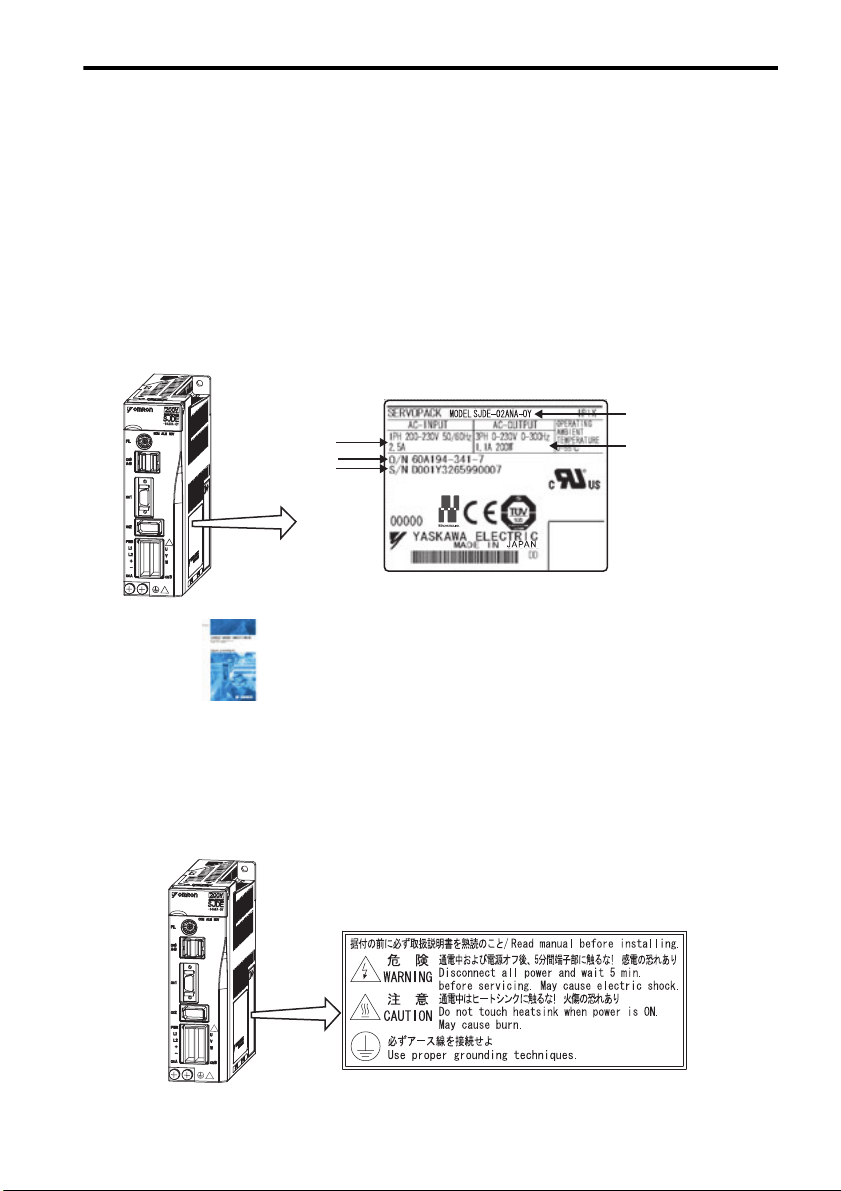
Confirm that the following items have been delivered together with the SERVOPACK. Verify that the
ordered product as received by the model number marked on the nameplate on the SERVOPACK.
If you find any irregularities such as incorrect SERVOPACK model, damages, and missing parts or
items, contact your Omron Yaskawa representative or the dealer from whom you purchased the products.
SJDE
SERVOPACK
Nameplate
Applicable
power supply
Order number
Serial number
One copy of this Instruction Manual 1 Connector Part Number JZSP-CHG9-1
SERVOPACK
model
Applicable motor
capacity
1.2 Warning Label
A warning label is located on the side of the SERVOPACK.
SJDE
SERVOPACK
13
SERVOPACK's Warning Label
1.3 Model Designation
1.3 Model Designation
SJDE—02 A N A - OY
JUNMA series SJDE SERVOPACK
Applicable servomotor capacity
Code
Output (W)
100
01
200
02
400
04
750
08
Power supply voltage
A: 200 VAC
Interface specification
N: MECHATROLINK-II
Design revision order
A
Sold by OMRON YASKAWA Motion Control B.V.
1.4 SERVOPACKs and Applicable Servomotors
Rated
Output
100 W SJME-01AM41-OY SJME-01AM4C-OY SJDE-01ANA-OY
200 W SJME-02AM41-OY SJME-02AM4C-OY SJDE-02ANA-OY
400 W SJME-04AM41-OY SJME-04AM4C-OY SJDE-04ANA-OY
750 W SJME-08AM41-OY SJME-08AM4C-OY SJDE-08ANA-OY
Without Brakes With Brakes
Servomotors SERVOPACKs
14
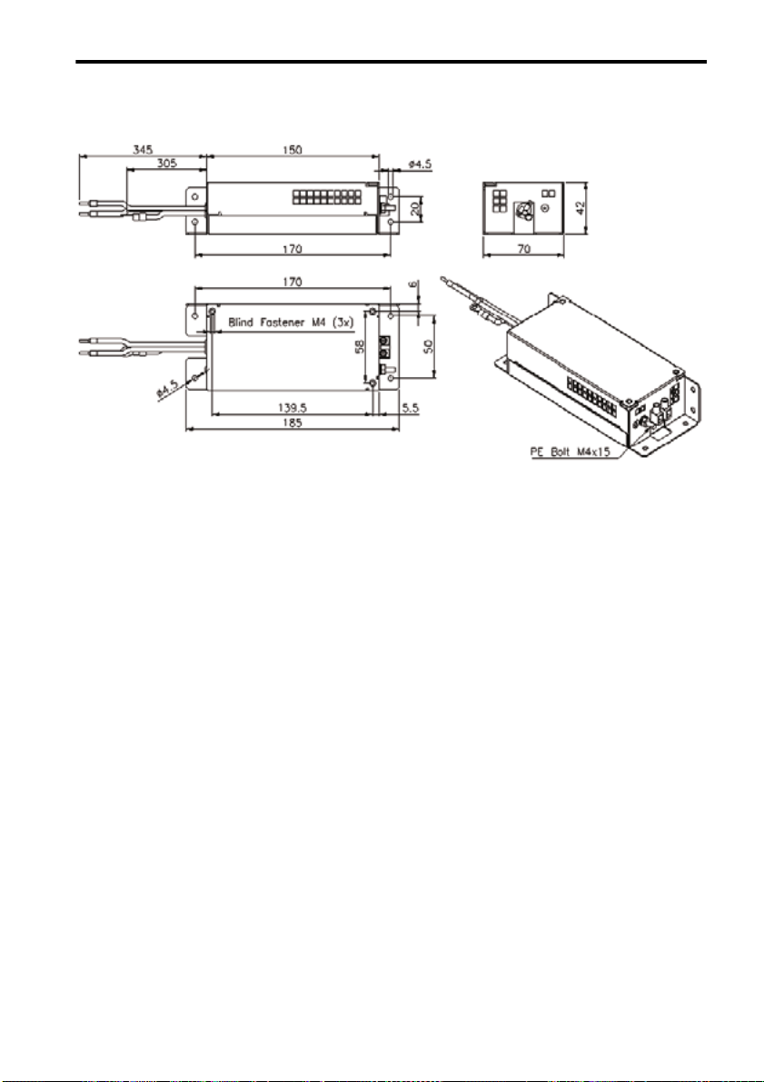
1.5 Part Names and Functions
Rotary switch for reference filter
setting(FIL)
Refer to 6.1 Filter Setting.
I/O signal connector (CN1)
Refer to 3.4 Main Circuit Wiring.
4
5
3
6
2
7
1
8
0
9
FIL
F
A
E
B
D
C
CN6
A/B
CN1
1.5 Part Names and Functions
Input voltage
Model
COM
ALM
RDY
Connector for MECHATROLINK-II
communications (CN6)
Refer to 3.4.6 Wiring the MECHATROLINK-
II Communication Connectors (CN6A and
CN6B).
Power supply indicator (PWR)
Connector for power supply/
regenerative unit (CNA)
Refer to 3.4.2 Wiring Connector for the
Power Supply/Regenerative Unit
(CNA).
CN2
PWR
L1
L2
U
V
W
CNBCNA
Encoder connector (CN2)
Refer to 3.4.4 Wiring the Encoder Connec-
tor (CN2).
Connector for servomotor main circuit
cable (CNB)
Refer to 3.4.3 Wiring Connector for the Ser-
vomotor Main Circuit Cable (CNB).
Ground terminal
MECHATROLINK-II Communications Settings
The SW1 and the SW2 switches set the MECHATROLINK-II communications settings. Settings that
have been changed are enabled when the power is turned OFF and then ON again.
DIP switch for MECHATROLINK-II
Rotary switch for MECHATROLINK-II
station address setting (SW1)
Refer to 3.8 Setting for
MECHATROLINK-II Communications.
Connector for personal
computer (CN9)
communications setting (SW2)
Refer to 3.8 Setting MECHATROLINK-II
Communications.
Servo status indicator (RDY)
Alarm indicator (ALM)
Refer to 8 Troubleshooting.
Indicator for MECHATROLINK-II
communications status (COM)
Refer to 3.8.5 MECHATROLINK-II
Communications Status Indicator COM LED
and 8 Troubleshooting.
15

1.6 Applicable Standards
1.6 Applicable Standards
JUNMA series SERVOPACKs comply with the following standards.
1.6.1 North American Safety Standards (UL, CSA)
Model
SERVOPACK SJDE
Servomotor SJME
* 1. Underwriters Laboratories Inc.
* 2. Canadian Standards Association.
UL∗1 Standards (UL File No.) CSA∗2 Standards
UL508C (E147823) CSA C22.2 No.14 UL
UL1004 (E165827) CSA C22.2 No.100 UL
1.6.2 European Directives
Model Low Voltage
SERVOPACK
Servomotor
* TÜV Product Services GmbH
Note: 1. Because SERVOPACKs and servomotors are built-in type, reconfirmation is
required after being installed in the final product.
SJDE EN50178 EN55011
SJME IEC60034-1
Directive
IEC60034-5
IEC60034-8
IEC60034-9
class A, group 1
class A, group 1
EMC Directive Certification
EMI EMS
EN61000-6-2 TUV PS*
EN55011
EN61000-6-2 TUV PS*
Certification
16
2 Installation
The following shows the installation location and method of the SERVOPACK.
2.1 Installation Conditions
Item Specifications
Operating temperature 0 ° C to +55 °C
Operating humidity 90% RH or less (with no condensation)
Storage temperature -20 ° C to +70 °C
Storage humidity 90% RH or less (with no condensation)
Installation site Free of corrosive gases
Altitude 1000 m or below
Vibration resistance
Shock resistance
Operating conditions Installation category (overvoltage category): II
Installation in a control
panel
Installation near a
Installation
Site
heating unit
Installation near a
source of vibration
Installation at a site exposed to corrosive gas
Free of dust and iron powder
Not subjected to moisture or lubrication oil such as cutting oil.
2
4.9m/s
2
19.6m/s
Pollution degree: 2
Protection class: IP1X (EN50178)
Design the control panel size, unit layout, and cooling method so that
the temperature around the SERVOPACK does not exceed 55 °C.
Note: To extend product life and maintain reli-
ability, keep the temperature inside the
control panel under 45 ° C.
Minimize the heat radiating from the heating unit as well as any
temperature rise caused by natural convection so that the temperature
around the SERVOPACK does not exceed 55 ° C.
Install a vibration isolator beneath the SERVOPACK to avoid subjecting
it to vibration.
Corrosive gas does not have an immediate effect on the SERVOPACK
but will eventually cause the electronic components and contactor-
related devices to malfunction. Take appropriate action to avoid corrosive gas.
2.1 Installation Conditions
17
2.2 Installation Method
2.2 Installation Method
Installation Method and Direction
• Install the SERVOPACK perpendicular to the wall.
• Connect the mounting holes securely to the mounting surface with M4 screws.
SJDE-08ANA-OY: Three mounting holes SJDE-01 to 04ANA-OY: Two mounting holes
SERVOPACK installation plate
M4 screw
M4 screw
M4 screw
SERVOPACK installation plate
M4 screw
M4 screw
Space between SERVOPACK Units
• Be sure to keep a space between adjacent SERVOPACK units as shown the following figure if they
are mounted inside the control panel. This allows the units to cool.
CAUTION
• Do not cover the inlet or outlet parts of the SERVOPACK and prevent any foreign objects, such as
metallic fragment, or combustibles from entering the product.
Failure to observe this caution may cause internal elements to deteriorate resulting in malfunction
or fire.
50 mm
min.
Air outlet
direction
30 mm
min.
10 mm
min.
18
50 mm
min.
Air inlet
direction
3 Wiring
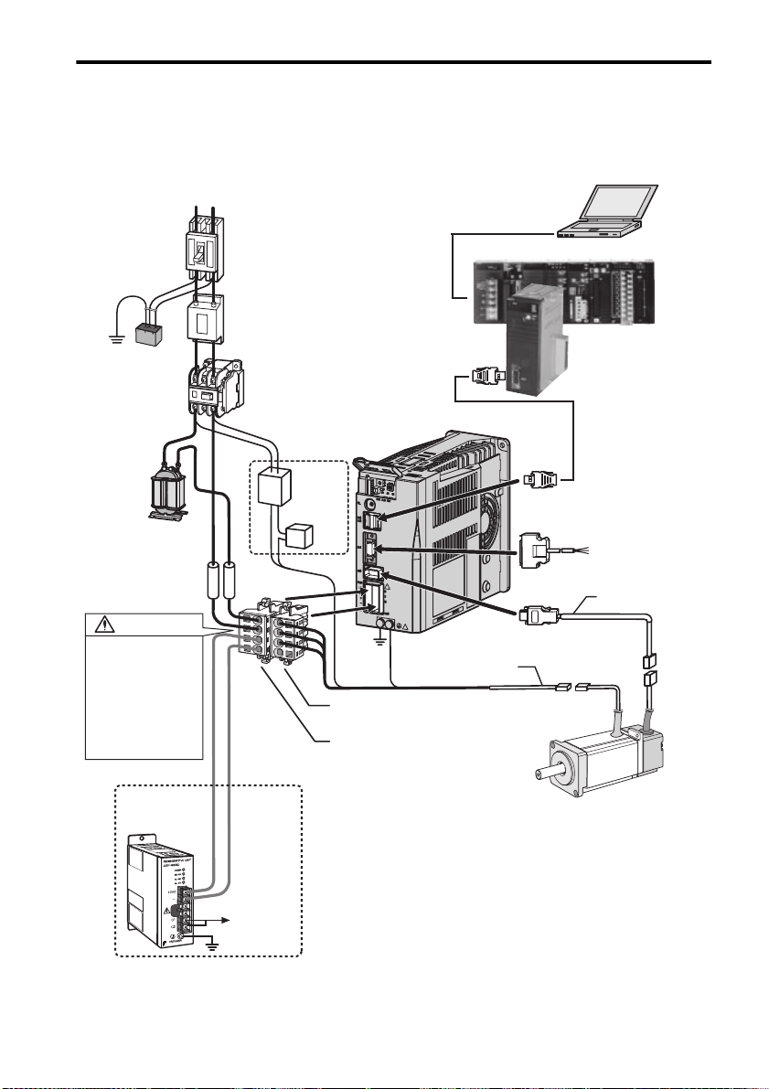
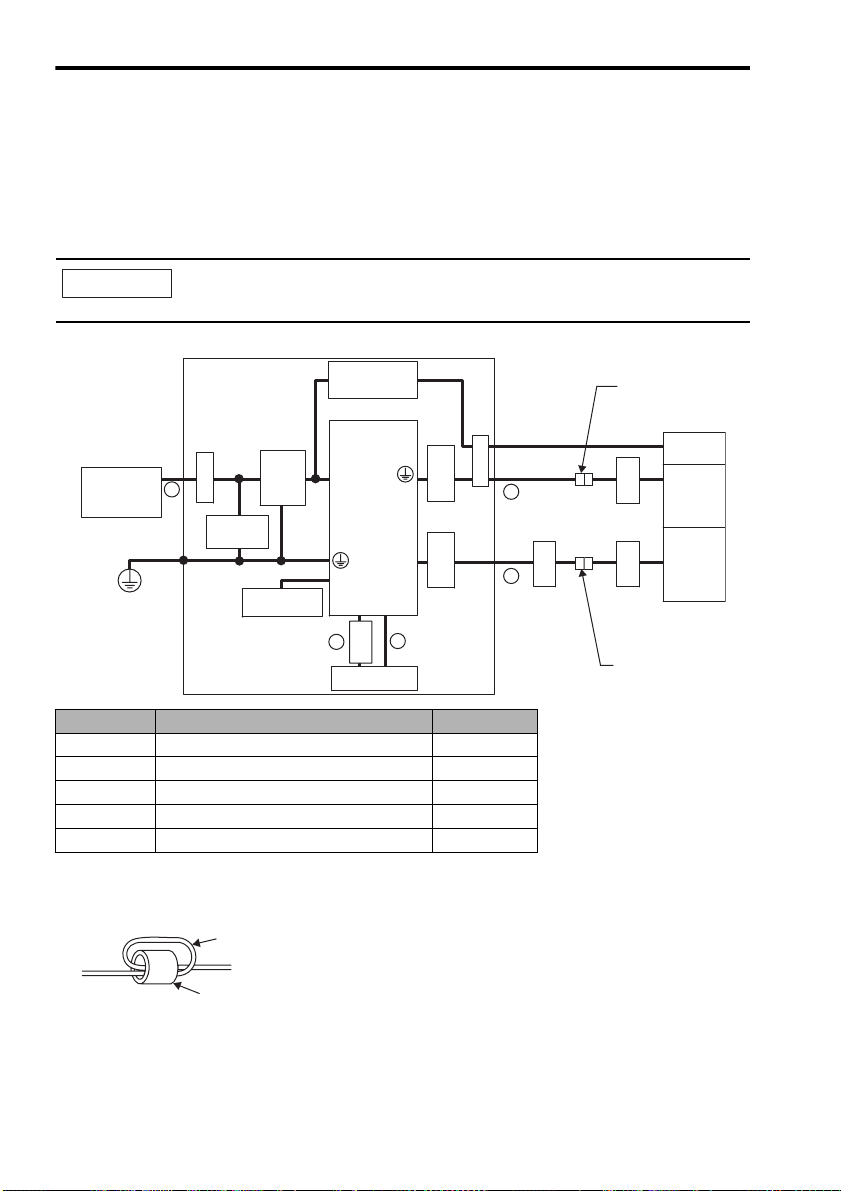
3.1 System Configuration
Power supply
Single-phase 200 VAC
L1 L2
Molded-case circuit breaker
To protect the equipment and wiring,
always connect a molded-case circuit
breaker.
Noise filter
Used to eliminate suppress noise
from power lines.
Surge protector
Protects the
system from
lightening surge.
AC reactor
Used for a power
supply harmonic
suppression.
Fuse
To protect the
equipment, always
install fuses.
WARNING
Correctly connect the
connectors CNA and CNB.
Incorrect wiring may result in
electric shock, injury, or
damage to the equipment.
After wiring, install the
connectors as explained in
3.8 Wiring the Power
Supply/Regenerative Unit
Connector (CNA) and 3.9
Wiring the Servomotor Main
Circuit Cable Connector
(CNB).
Used for a
regenerative unit.
Regenerative unit
Used if regenerative
energy is high.
Magnetic contactor
Used to turn OFF the servo
power supply when using a
regenerative unit or a
emergency stop.
Used for a
servomotor
with a brake.
24-VDC
power
supply
Brake relay
n
SJDE
SERVOPACKs
*1
*
Servomotor main circuit
cable (for relay)
Connectors for servomotor
main circuit cable (CNB
Connectors for power
supply/regenerative unit
(
)
CNA
Personal computer
software: CX-One
)
SJME
Servomotors
3.1 System Configuration
CJ-series PLC
CJ1 series
Position control unit
CJ1W-NCF71
MECHATROLINK-II
connection
I/O Signal cable
Connects to
CJ-Series PLC
To the control
circuits of
magnetic
contactor
* 1. Prepare a 24-VDC power supply for the brake separately from the sequence power supply.
19

3.2 Standard Connection
3.2 Standard Connection
Power supply
Single-phase 200 VAC to 230 VAC
50/60Hz
L1 L2
Molded-case circuit breaker
Surge protector
AVR 2
24 VDC power
supply
Noise
filter
200 VAC
to
230 VAC
+24V 0V
MC1
SW1 SW2
MC1
Regenerative unit
Controller
130Ω
MC1
Spark
killer
C1 C2
JUSP-
RG08D
MECHATROLINK-II
cable
Shielded wire
MC1
Ry1
Flywheel
diode
Shielded wire
AVR 1*
24 VDC
power supply
200 VAC to
230 VAC
CNA CNB
Fuse
1
L1
Reactor
Fuse
L2
2
3
/TXD
/RXD
GND
/S
Ter m i nator
130Ω
24VIN
/EXT1
/DEC
N-OT
P-OT
E-STP
ALM
/BK
SG_COM
+
4
-
CN9
1
2
3,4
CN6A
A2
S
A3
Shell
CN6B
B2
B3
CN1
5
1
2
3
4
6
12
13
7
+
Y4
Y5
+
24V
0V
SERVOPACK
3.3kΩ
3.3kΩ
3.3kΩ
3.3kΩ
3.3kΩ
Ry1
CN2
Shell
1
2
3
1
2
3
4
5
6
7
8
9
10
Varistor
PG5V
PG0V
U
V
W
Shielded wire
A+
A-
B+
B-
/Z
U
V
W
Shielded wire
5
6
1
2
V
3
4
1
2
3
4
5
6
7
8
9
10
12
Brake
U
Servomotor
W
FG
Encoder
Note: 1. AVR1:24 VDC
power supply for
brake
AVR2:24 VDC power supply for sequence
PB1:Power OFF switch
PB2:Power ON switch
MC1:Magnetic contactor
Ry1:Brake relay
• Parts example
Spark killer Okaya Electric Industries
Flywheel
diode
Co., Ltd.
Toshiba Corporation 1NH42
CRE-50500
Brake relay OMRON Corporation MY series
Varistor NIPPON CHEMI-CON
CORPORATION
TNR7V121K
20
3.3 Precautions on Wiring
2. The ground protection circuit is designed for ground fault inside the motor
windings while the motor is running. Therefore, it may not protect the system
under the following conditions.
• A low-resistance ground fault occurs between the main circuit cable and connector for the servomotor.
• The power supply is turned ON during a ground fault.
To configure a safer system, install an earth leakage breaker for protection
against overloads and short-circuit, or install an earth leakage breaker for
ground protection combined with a wiring circuit breaker.
3. Position information is not stored in the SERVOPACK, so this information will be
lost if the power supply is turned OFF. If this information is required for the
operation of the host controller, make sure that the system has an emergency
stop signal (E-STP) that will stop operations without turning OFF the power
supply.
* 1. Prepare a 24 VDC power supply for sequence separately from the 24 VDC power supply for brake.
3.3 Precautions on Wiring
WARNING
• Be sure to correctly ground the SERVOPACK and the servomotor.
• Wiring must be performed by an authorized person qualified in electrical work.
• Configure the circuit’s power supply to be automatically cut off if E-STP signal is OFF at occurrence of emergency stop. (Refer to 3.7.3 Emergency Stop Signal Input.)
The residual voltage rotates the servomotor for a few seconds after the power supply has been
turned OFF, and may result in injury or damage to the equipment. Be sure to completely stop the
motor by turning OFF the servo using the emergency stop.
Position information is not stored in the SERVOPACK, so this information will be lost if the power
supply is turned OFF. This information cannot be read again if the power supply is turned OFF.
• When using the servomotor for a vertical axis, install safety devices to prevent workpieces from falling off because of alarms. Workpiece’s falling off may result in injury or malfunction.
• Configure the interlock circuit so that the system is interlocked to avoid injury whenever the protective cover on the machine is opened or closed.
3.3.1 Protection for Power Supply Line
• Use a molded-case circuit breaker and fuse to protect the power supply line. The SERVOPACK connects directly to a commercial power supply without a transformer, so always use a circuit breaker
and fuse to protect the servo system from accidental high voltage.
3.3.2 Caution for Grounding
Consider the following conditions when grounding the SERVOPACK.
• For a ground wire, use as thick a cable as possible (2.0 mm2 or thicker).
• A ground resistance of 100 (Ω) or less is recommended.
• Ground to one point only.
21

3.3 Precautions on Wiring
3.3.3 Caution for Cable
• For wiring, use the specified cables. Use cables that are as short as possible.
• Do not bend or apply tension to cables. The conductor of a signal cable is thin (0.08 to 0.12 mm
so handle the cables carefully.
2
),
3.3.4 Power Loss
Power Loss with SERVOPACK Rated Output
Main
Circuit
Powe r
Supply
Single-
phase
200 V
Note: Values obtained with the servomotor rated output.
SERVOPACK Output Current
Model Capacity
SJDE-01ANA-OY 100 W 0.84 6 9 15
SJDE-02ANA-OY 200 W 1.1 8 17
SJDE-04ANA-OY 400 W 2.0 16 25
SJDE-08ANA-OY 750 W 3.7 27 36
(Effective
Val ue)
A
Main Circuit
Power Loss
W
Control Circuit
Power Loss
W
Tot a l Powe r
Loss
W
3.3.5 SERVOPACKs and Applicable Peripheral Devices
SERVOPACK Power
Ty pe Capa-
SJDE01ANA-OY
SJDE02ANA-OY
SJDE04ANA-OY
SJDE08ANA-OY
Manufacturer
Note: It is recommended to use a general-purpose circuit breaker of the sensed current 200 mA or more, or a cir-
* 1. Nominal value at the rated load. The specified derating is required to select the appropriate molded-case
circuit breaker.
* 2. Cut-off characteristics (25 °C): 200 % two seconds min. and 700 % 0.01 seconds min.
100 W
200 W
400 W
750 W
cuit breaker for inverters (for high-frequency).
city
Supply
Capacity
SERVO-
PAC K
Power sup-
ply
Capacity of
per
kVA
0.40 4 0KLK
0.75 X5053
1.2 8 X5054
2.2 16 0KLK
Molded-
case
Circuit
Breaker
Arms
--Littelfuse
*1 *2
Power
supply
Capacity
and
Model of
External
Fuse
015.T
(15 Arms)
030.T
(30 Arms)
Inc.
Inrus
Mag-
h
netic
Cur-
Contac-
rent
A0-p
tor
30 HI-11J R7A-
60 HI-15J R7A-
-Yaskawa
Controls
Co., Ltd.
Noise
Filter
FIZN105
-BE
FIZN109
-BE
Block
Elek-
tronik
Surge
Protector
xCxM-
R
601BQZ-4
Okaya
Electric
Industries
Co., Ltd.
AC
Reactor
X5052
X5056
Yaskawa
Controls
Co., Ltd.
IMPORTANT
Ground Fault
The ground protection circuit is designed for ground fault inside the motor windings while the
motor is running. Therefore, it may not protect the system under the following conditions.
• A ground fault occurs between the main circuit cable and connector for the servomotor.
• The power supply is turned ON during a ground fault.
To configure a safer system, install an ground fault detector for protection against overloads
22
and short-circuit, or install an ground fault detector combined with a wiring circuit breaker for
ground protection.
3.3.6 Noise Prevention
Example of Wiring for Noise Prevention
3.3 Precautions on Wiring
Noise filter
Min. wire
size
: 3.5 mm
*
1.
2LF
Casing
2
P
Operation relay sequence
User signal generating circuit
1LF
P
Casing
Casing
Min. wire size: 3.5 mm
*2.
P
2
*1.
AVR
(Grounding)
Casing
2 mm2 or larger
Min. wire size:
3.5 mm
Casing
200 VAC
* 1. For the wires connected to the casings for installation purposes, use wires with a diameter of 3.5 mm2 or
larger. Flat braided copper wires are recommended.
* 2. Use twisted pair wires for section P.
SJDE
SERVOPACK
L1
L2
2
*1.
Grounding plate
Groudning: Ground to one point only.
Min. grounding resistance: 100 Ω
CN1
CN2
U
V
W
Min. wire
size
: 3.5 mm
Min. wire
size
: 3.5 mm
2
2
Servomotor
M
(FG)
PG
Correct Grounding
• Servomotor frame grounding:
Be sure to connect the FG grounding terminal on the frame of the servomotor to the grounding terminal on the SERVOPACK.
• Be sure to ground the grounding terminal of the SERVOPACK.
• If the wires of the servomotor’s main circuit are laid in a metal conduit, ground the conduit and the
grounding box.
One-point grounding must be used.
23
3.3 Precautions on Wiring
Noise Filters
Use a block type noise filters to prevent any noise interference from the power-supply line.
The following table lists the recommended noise filters for several SERVOPACK models.
Application of Noise Filters
Power-Supply
Voltage
Single-
phase
230 V +10%
50-60 Hz
Filter dimensions for model R7A-FIZN105-BE
SERVOPACK
Model
SJDE-01ANA-OY
SJDE-02ANA-OY
SJDE-04ANA-OY
SJDE-08ANA-OY
Recommended Noise Filters
Model Specifications Manufacturer
R7A-FIZN105-BE Single-phase 250 VAC, 5A
R7A-FIZN109-BE Single-phase 250 VAC, 9A
Block
Transformatoren
Elektronik
GmbH & Co. KG.
24
Filter dimensions for model R7A-FIZN109-BE
3.3 Precautions on Wiring
25
3.3 Precautions on Wiring
3.3.7 Installation and Wiring Conditions on CE Marking
Installation Conditions of EMC Directives
To adapt a combination of a SJME servomotor and a SJDE SERVOPACK to EMC Directives
(EN55011, group 1, class A and EN61000-6-2), the following conditions must be satisfied.
Because SERVOPACKs are built-in type, reconfirmation is required after being installed in the final
product.
IMPORTANT
Power supply
Single-phase
200 VAC
PE
The actual EMC level may differ depending on the actual system’s configuration, wiring, and
other conditions.
Ground Plate
Brake power
supply
SERVOPACK
Noise
Surge
protector
filter
Regenerative
unit
5
Clamp
U, V, W
L1, L2
CN2
+,–
CN1CN6
2
1
core
Ferrite
Host controller
Clamp
core
Ferrite
Ferrite
core
3
core
4
Ferrite
Cable joint
core
Ferrite
core
Ferrite
Cable joint
Servomotor
Encoder
Symbol Cable Name Specifications
A I/O Signals cable Shielded wire
B MECHATROLINK-II Communication cable Shielded wire
C Servomotor Main circuit cable Shielded wire
D Encoder cable Shielded wire
E AC Line cable Shielded wire
Attaching the Ferrite Core
Coil the servomotor main circuit cable (as a connection) around the ferrite core with two turns, then
attach them by the SERVOPACK. Refer to the diagram in the previous page.
Cable (two turns)
Brake
Ferrite core
Note: Recommended Ferrite-core
Model: ESD-SR-25 (Tokin. Corp.)
26
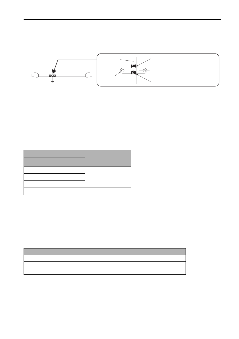
Fixing the Cable
Fix and ground the cable shield using a piece of conductive metal (cable clamp).
• Example of Cable Clamp
3.4 Main Circuit Wiring
Host
controller
side
Ground plate
Cable
Cable
clamp
Shield (cable sheath stripped)
Fix and ground the cable shield
using a piece of conductive metal.
Remove paint on mounting surface.
Shield Box
A shield box, which is a closed metallic enclosure, should be used for shielding magnetic interference
(EMI). The structure of the box should allow the main body, door, and cooling unit to be attached to the
ground. The box opening should be as small as possible.
3.3.8 Other Precautions
• Whether the electricity is served or not to the motor, do not use the motor being rotated from the
outside.
• When restarting the power supply soon after turning OFF, alarm may occur to the SERVOPACK.
Refer to the power supply holding time in the following table to restart the power supply correctly.
SERVOPACK Min. Waiting Time
Model Capacity
SJDE-01ANA-OY 100 W
SJDE-02ANA-OY 200 W
SJDE-04ANA-OY 400 W
SJDE-08ANA-OY 750 W
before Restarting
(s)
20
30
3.4 Main Circuit Wiring
• SJDE SERVOPACKs are suitable where the power supply is less than 5000 Arms (230 V max.).
• SERVOPACKs must be used with UL-listed fuses or molded-case circuit breakers, in accordance
with the National Electrical Code (NEC).
•Use 75 ° C heat-resistant copper wires or an equivalent.
3.4.1 SERVOPACK Main Circuit Cables
Cable Types
Symbol Name Allowable Conductor Temperature
PVC Normal vinyl cable
IV 600 V vinyl cable
HIV Temperature-resistant vinyl cable
• Wire sizes are selected for three cables per bundle at 40 ° C ambient temperature with the rated
current.
• Use cables with a minimum withstand voltage of 600 V for main circuits.
• If cables are bundled in PVC or metal ducts, consider the reduction ratio of the allowable current.
• Use heat-resistant cables under high ambient or panel temperatures where normal vinyl cables will
rapidly deteriorate and will not be able to use in a short period of time.
• Do not use cables under continuous regenerative state.
27
−
60 ° C
75 ° C
3.4 Main Circuit Wiring
Wire Size and Allowable Current
The following table shows the wire size and allowable current for three cables. Use a cable whose
specifications meet or are less than allowable current in the table.
• 600 V Heat-resistant Vinyl Cables (HIV)
AWG
Note: The values in the table are only for reference.
Nominal Cross
Size
Section Diameter
20 0.5 19/0.18 39.5 6.6 5.6 4.5
- 0.75 30/0.18 26.0 8.8 7.0 5.5
18 0.9 37/0.18 24.4 9.0 7.7 6.0
16 1.25 50/0.18 15.6 12.0 11.0 8.5
14 2.0 7/0.6 9.53 23 20 16
mm
2
Configuration
Number of
2
wires/mm
Conductive
Resistance
2
Ω/mm
Allowable Current at Ambient Temperature
A
30 ° C 40 ° C 50 ° C
Power Supply Input Terminals (L1, L2), Motor Connection Terminals (U, V,
W), and Regenerative Unit Connection Terminals (+, -)
CapacityWSERVOPACK Type Terminal Symbol
L1, L2 U, V, W +, 100
200
400
750
Note: Connectors are used for all wiring.
SJDE-01ANA-OY
SJDE-02ANA-OY
SJDE-04ANA-OY
SJDE-08ANA-OY
HIV1.25 mm
HIV2.0 mm
2
2
HIV1.25mm
Wiring length:
20 m max.
2
HIV1.25mm
Wiring length:
0.5 m max.
2
Ground Terminal ( )
Wire Size Terminal Screw Size Tightening Torque
HIV 2.0 mm
2
min.
M4 1.2 to 1.4 Nxm
28
Loading...