


 Loading...
Cat. No.Z249-E1-04
RFID System
V680 Series
ID Controller
USER´S MANUAL

RFID System
V680 Series
User's Manual
ID Controller
V680-CA5D01-V2
V680-CA5D02-V2
Cat. No. Z249-E1-04

Introduction
Thank you for purchasing a V680-series RFID System. This manual describes the functions, performance, and application methods needed for optimum use of the V680-series RFID System.
Please observe the following items when using the RFID System.
•Allow the RFID System to be installed and operated only by qualified specialist with a sufficient knowledge of electrical systems.
•Read and understand this manual before attempting to use the RFID System and use the RFID System correctly.
•Keep this manual in a safe and accessible location so that it is available for reference when required.

Introduction READ AND UNDERSTAND THIS DOCUMENT
SECTION 1 Product Overview
SECTION 2 Installation, Connections, and Wiring
SECTION 3 Preparations for Communications
SECTION 4 Functions
SECTION 5 Communications
SECTION 6 Troubleshooting
SECTION 7 Appendices
RFID System
V680-CA5D01-V2 |
ID Controller |
V680-CA5D02-V2 |
ID Controller |
7 SECTION 6 SECTION 5 SECTION 4 SECTION 3 SECTION 2 SECTION 1 SECTION Introduction
User’s Manual

Introduction
2
Introduction
READ AND UNDERSTAND THIS DOCUMENT
Please read and understand this document before using the products. Please consult your OMRON representative if you have any questions or comments.
WARRANTY
OMRON’s exclusive warranty is that the products are free from defects in materials and workmanship for a period of one year (or other period if specified) from date of sale by OMRON.
OMRON MAKES NO WARRANTY OR REPRESENTATION, EXPRESS OR IMPLIED, REGARDING NON-INFRINGEMENT, MERCHANTABILITY, OR FITNESS FOR PARTICULAR PURPOSE OF THE PRODUCTS. ANY BUYER OR USER ACKNOWLEDGES THAT THE BUYER OR USER ALONE HAS DETERMINED THAT THE PRODUCTS WILL SUITABLY MEET THE REQUIREMENTS OF THEIR INTENDED USE. OMRON DISCLAIMS ALL OTHER WARRANTIES, EXPRESS OR IMPLIED.
LIMITATIONS OF LIABILITY
OMRON SHALL NOT BE RESPONSIBLE FOR SPECIAL, INDIRECT, OR CONSEQUENTIAL DAMAGES, LOSS OF PROFITS OR COMMERCIAL LOSS IN ANY WAY CONNECTED WITH THE PRODUCTS, WHETHER SUCH CLAIM IS BASED ON CONTRACT, WARRANTY, NEGLIGENCE, OR STRICT LIABILITY.
In no event shall responsibility of OMRON for any act exceed the individual price of the product on which liability is asserted.
IN NO EVENT SHALL OMRON BE RESPONSIBLE FOR WARRANTY, REPAIR, OR OTHER CLAIMS REGARDING THE PRODUCTS UNLESS OMRON’S ANALYSIS CONFIRMS THAT THE PRODUCTS WERE PROPERLY HANDLED, STORED, INSTALLED, AND MAINTAINED AND NOT SUBJECT TO CONTAMINATION, ABUSE, MISUSE, OR INAPPROPRIATE MODIFICATION OR REPAIR.
SUITABILITY FOR USE
THE PRODUCTS CONTAINED IN THIS DOCUMENT ARE NOT SAFETY RATED. THEY ARE NOT DESIGNED OR RATED FOR ENSURING SAFETY OF PERSONS, AND SHOULD NOT BE RELIED UPON AS A SAFETY COMPONENT OR PROTECTIVE DEVICE FOR SUCH PURPOSES. Please refer to separate catalogs for OMRON's safety rated products.
OMRON shall not be responsible for conformity with any standards, codes, or regulations that apply to the combination of products in the customer’s application or use of the product.
At the customer’s request, OMRON will provide applicable third party certification documents identifying ratings and limitations of use that apply to the products. This information by itself is not sufficient for a complete determination of the suitability of the products in combination with the end product, machine, system, or other application or use.
The following are some examples of applications for which particular attention must be given. This is not intended to be an exhaustive list of all possible uses of the products, nor is it intended to imply that the uses listed may be suitable for the products:
•Outdoor use, uses involving potential chemical contamination or electrical interference, or conditions or uses not described in this document.
•Nuclear energy control systems, combustion systems, railroad systems, aviation systems, medical equipment, amusement machines, vehicles, safety equipment, and installations subject to separate industry or government regulations.
•Systems, machines, and equipment that could present a risk to life or property.
Please know and observe all prohibitions of use applicable to the products.
NEVER USE THE PRODUCTS FOR AN APPLICATION INVOLVING SERIOUS RISK TO LIFE OR PROPERTY WITHOUT ENSURING THAT THE SYSTEM AS A WHOLE HAS BEEN DESIGNED TO ADDRESS THE RISKS, AND THAT THE OMRON PRODUCT IS PROPERLY RATED AND INSTALLED FOR THE INTENDED USE WITHIN THE OVERALL EQUIPMENT OR SYSTEM.
PERFORMANCE DATA
Performance data given in this document is provided as a guide for the user in determining suitability and does not constitute a warranty. It may represent the result of OMRON’s test conditions, and the users must correlate it to actual application requirements. Actual performance is subject to the OMRON Warranty and Limitations of Liability.
CHANGE IN SPECIFICATIONS
Product specifications and accessories may be changed at any time based on improvements and other reasons.
It is our practice to change model numbers when published ratings or features are changed, or when significant construction changes are made. However, some specifications of the product may be changed without any notice. When in doubt, special model numbers may be assigned to fix or establish key specifications for your application on your request. Please consult with your OMRON representative at any time to confirm actual specifications of purchased products.
DIMENSIONS AND WEIGHTS
Dimensions and weights are nominal and are not to be used for manufacturing purposes, even when tolerances are shown.
ERRORS AND OMISSIONS
The information in this document has been carefully checked and is believed to be accurate; however, no responsibility is assumed for clerical, typographical, or proofreading errors, or omissions.
PROGRAMMABLE PRODUCTS
OMRON shall not be responsible for the user’s programming of a programmable product, or any consequence thereof.
COPYRIGHT AND COPY PERMISSION
This document shall not be copied for sales or promotions without permission. This document is protected by copyright and is intended solely for use in conjunction with the product. Please notify us before copying or reproducing this document in any manner, for any other purpose. If copying or transmitting this document to another, please copy or transmit it in its entirety.
RFID System
User's Manual

Introduction
Safety Precautions
● Alert Symbols for Safe Use
The following symbols are used in this manual to indicate precautions that must be observed to ensure safe use of the V680-CA5D01-V2 / -CA5D02-V2. The precautions provided here contain important safety informa-
tion. Be sure to observe these precautions.
The following signal words are used in this manual.
Indicates a potentially hazardous situation which, if not avoided, will result in minor or
 WARNING moderate injury, or may result in serious injury or death. Additionally, there may be significant property damage.
● Meanings of Alert Symbols
Indicates general prohibitions for which there is no specific symbol.
● Warning
 WARNING
This Product is not designed to be used either directly or indirectly in applications that detect human presence for the purpose of maintaining safety. Do not use this Product as a sensing device for protecting human lives.
Introduction
Regulations and Standards
The V680-CA5D01-V2 / -CA5D02-V2 conform to the following overseas regulations and standards. 1.UL Standards
The V680-CA5D01-V2 and V680-CA5D02-V2 meet UL (Underwriter's Laboratories Inc.) conditions. UL508
Connect to either circuit type (1) or (2) listed below.
(1) Limited Voltage/Current Circuit (Approved under UL508)
A circuit that uses the secondary windings of an isolation transformer as its power supply and fulfills the following conditions:
•Maximum voltage: 30 Vrms (42.4 V peak) and
•Maximum current: (a) 8 A (including short-circuits) or
(b)Current limited by a circuit protection device (e.g., fuse) with the ratings listed in the following table.
No-load voltage (V peak) |
Maximum current rating (A) |
||
|
|
|
|
0 to 20 |
5.0 |
|
|
|
|
|
|
Over 20 to 30 |
100 |
|
|
|
|
|
|
|
|
Peak voltage |
|
|
|
|
|
RFID System |
3 |
User's Manual |

Introduction
Introduction
(2) A class 2 circuit with a maximum voltage of 30 Vrms (42.4 V peak) that uses a class 2 power supply unit conforming to UL1310 or a class 2 transformer that conforms to UL1585 as its power source.
2. EMC Standards
The V680-CA5D01-V2 and V680-CA5D02-V2 meet the requirements of the following EC Directives. EMC Standard: EN 61000-6-2
EN 61000-6-4
Precautions for Safe Use
Be sure to observe the following precautions to ensure safe use of the Product.
1.Do not use the Product in environments with flammable, explosive, or corrosive gasses.
2.Do not attempt to disassemble, repair, or modify the Product.
3.Tighten the base mounting screws and terminal block screws securely.
4.Be sure to use crimp terminals of the specified size for wiring.
5.If any cable has a locking mechanism, make sure that it has been locked before using the cable.
6.Make sure the power supplied by the DC power supply unit is within the rated power supply voltage (24 VDC +10%/−15%) before using the Product.
7.Do not connect the power supply in reverse.
8.Do not allow water or wires to enter the Product through gaps in the case. Otherwise, fire or electric shock may occur.
9.Turn OFF the power to the Controller before attaching or removing an Amplifier or Antenna.
10.If an error is detected in the Product, immediately stop operation and turn OFF the power supply. Consult with an OMRON representative.
11.Dispose of the Product as industrial waste.
12.Observe all warnings and precautions given in the body of this manual.
4 |
RFID System |
User's Manual |

Introduction
Precautions for Correct Use
Always observe the following precautions to prevent operation failure, malfunctions, and adverse effects on
performance and equipment.
1. Installation Environment
Do not use the Product in the following locations.
•Locations exposed to corrosive gases, dust, metallic powder, or salts
•Locations not within the specified operating temperature range
•Locations subject to rapid changes in temperature or condensation
•Locations not within the specified operating humidity range
•Locations subject to direct vibration or shock outside the specified ranges
•Locations subject to spray of water, oil, or chemicals
2.Installation
•This Product uses a frequency band of 13.56 MHz to communicate with ID Tags. Some transceivers, motors, inverters, switching power supplies, etc., generate electrical noise that will affect these communications. If any of these devices are located in the vicinity of the Product, they may affect communications with ID Tags, and may possibly damage the ID Tags. Prior to using the Product in the vicinity of any of these devices, perform a test to determine whether the Product can be used under the resulting influence.
•Observe the following precautions to minimize the effects of normal noise.
(1)Ground the ground terminal on the Product and all metal objects in the vicinity of the Product to 100 Ω or less.
(2)Do not use the Product near high-voltage or high-current lines.
•The Product is not waterproof. Do not use it in an environment where mist is present.
•Do not expose the Product to chemicals that adversely affect the Product materials.
•Use a tightening torque of 1.2 N·m max.
•If multiple Antennas are mounted near each other, communications performance may decrease due to mutual interference. Refer to Installing Antennas in the V680 Series User's Manual for Amplifiers, Antennas, and ID Tags (Cat. No. Z262, Z248) and check to make sure there is no mutual interference.
3.Storage
Do not store the Product in the following locations.
•Locations exposed to corrosive gases, dust, metallic powder, or salts
•Locations not within the specified operating temperature range
•Locations subject to rapid changes in temperature or condensation
•Locations not within the specified storage humidity range
•Locations subject to direct vibration or shock outside the specified ranges
•Locations subject to spray of water, oil, or chemicals
4.Cleaning
•Do not clean the Product with paint thinner, benzene, acetone, or kerosene. These chemicals will dissolve the resin materials and case coating.
Introduction
RFID System |
5 |
User's Manual |

Symbols of Meanings Introduction
Introduction
5. Communications with the Host Device
Communicate with the host device only after confirming that the CIDRW Controller has started. Also, unstable signals may occur at the host interface when the CIDRW Controller is started. When initializing operation, clear the reception buffer at the host device or take other suitable methods to clear unwanted signals.
6. Startup Precaution
Never turn OFF the power supply while the CIDRW Controller is starting, including when power is turned ON, when the mode is changed, or when the CIDRW Controller is being reset. Doing so may damage the CIDRW Controller.
Meanings of Symbols
Indicates particularly important points related to a function, including precautions and application advice.
Indicates page numbers containing relevant information.
Indicates reference to helpful information and explanations for difficult terminology.
6 |
RFID System |
User's Manual |

|
|
Introduction |
|
|
|
Table of Contents |
|
|
|
|
|
|
|
|
|
|
|
Introduction |
|
|
|
|
|
|
|
|
|
Safety Precautions |
3 |
|
|
|
|
Regulations and Standards |
3 |
|
|
|
|
Precautions for Safe Use |
4 |
|
|
|
|
Precautions for Correct Use |
5 |
|
|
|
|
Meanings of Symbols |
6 |
|
|
|
|
Table of Contents |
7 |
|
|
|
Introduction
SECTION 1 Product Overview |
9 |
|
|
|
|
|
|
|
|
Features |
10 |
|
|
|
|
Part Names and Functions |
13 |
|
|
|
|
System Configuration |
19 |
|
|
|
|
Application Flowchart |
25 |
|
|
|
SECTION 2 Installation, Connections, and Wiring |
27 |
|
|
|
|
|
|
|
|
|
|
|
|
|
|
|
|
|
Installation |
28 |
|
|
|
|
|
|
|
|
|
|
Connection and Wiring |
30 |
|
|
|
|
|
|
|
|
|
SECTION 3 Preparations for Communications |
57 |
|
|
||
|
|
|
|
|
|
|
|
|
|
|
|
|
Switch Settings |
58 |
|
|
|
|
|
|
|
|
|
|
Trial Operation |
76 |
|
|
|
|
|
|
|
|
|
SECTION 4 Functions |
79 |
|
|
|
|
|
|
|
|
|
|
|
|
|
|
|
|
|
Trigger Input |
80 |
|
|
|
|
|
|
|
|
|
|
Write Protection |
81 |
|
|
|
|
|
|
|
|
|
|
Tag Service Life Check |
91 |
|
|
|
|
|
|
|
|
|
|
Tag Memory Check |
93 |
|
|
|
|
|
|
|
|
|
|
Tag Memory Error Correction |
94 |
|
|
|
|
|
|
|
|
|
|
Write Command Memory |
95 |
|
|
|
|
|
|
|
|
|
|
Noise Monitor Function |
96 |
|
|
|
|
|
|
|
|
|
|
|
RFID System |
|
7 |
|
|
|
|
|||
|
|
User’s Manual |
|
||
|
|
|
|
|
|
Introduction
Introduction
SECTION 5 Communications |
97 |
|
|
|
|
|
|
|
|
Tag Operation and Command Status |
98 |
|
|
|
|
V600-V680 Command Correspondence |
101 |
|
|
|
|
V680 Commands |
103 |
|
|
|
|
V600 Commands |
172 |
|
|
|
SECTION 6 Troubleshooting |
237 |
|
|
|
|
|
|
|
|
Self-diagnostic Function |
238 |
|
|
|
|
Error Lists |
240 |
|
|
|
|
Errors and Countermeasures |
244 |
|
|
|
|
Maintenance and Inspection |
245 |
|
|
|
|
Troubleshooting |
246 |
|
|
|
SECTION 7 Appendices |
251 |
|
|
|
|
|
|
|
|
Specifications and Dimensions |
252 |
|
|
|
|
Characteristics According to Operating Conditions |
256 |
|
|
|
|
Tag Memory Map |
265 |
|
|
|
|
Tag Memory Capacity and Memory Type |
266 |
|
|
|
|
ASCII Table |
267 |
|
|
|
|
Degree of Protection |
268 |
|
|
|
|
Revision History |
270 |
|
|
|
8 |
RFID System |
User’s Manual |
|
|
|

SECTION 1
Product Overview
|
|
Features |
10 |
|
|
|
|
|
|
Part Names and Functions |
13 |
|
|
||
|
|
|
|
|
|
System Configuration |
19 |
|
|
||
|
|
|
|
|
|
Application Flowchart |
25 |
|
|
||
|
|
|
|
RFID System
User’s Manual
Overview Product 1 SECTION
9
Features 1 SECTION
10
SECTION 1
Product Overview
Features
The V680-CA5D01-V2 / -CA5D02-V2 ID Controllers connect to V680-HA63 Amplifiers and V680-HS@@
Antennas, or to V680-H01 Antennas, to read and write data for V680-series ID Tags according to commands from the host device. The ID Controller returns the results of executing these commands as responses to the host device.
The ID Controller can communicate with Tags that conform to ISO 18000-3 (ISO 15693). The ID Controller may not be able to communicate with Tags that are not V680-series Tags. Always confirm that communications are possible in advance.
RFID System
User’s Manual

SECTION 1
Product Overview
Differences between the V680-CA5D@@ and V680-CA5D@@-V2
The following functions have been added to the V680-CA5D@@-V2 in addition to those found on the V680-CA5D@@. These functions are upward-compatible with the V680-CA5D@@, so the V680CA5D@@ can be directly replaced by the V680-CA5D@@-V2.
New Commands Added
The following commands have been added.
READ TAG MEMORY |
QR |
Reads the Tag's memory contents. Also uses a memory check code to inspect |
ERROR CORRECTION |
|
data reliability. |
|
|
|
WRITE TAG MEMORY |
QW |
Writes data to the memory of the Tag. Also writes the memory check code for the |
ERROR CORRECTION |
|
data reliability inspection to the memory of the Tag. |
|
|
|
READ ID |
ID |
Reads the Tag's ID code. |
|
|
|
UID ADDITION SET |
US |
Sets whether or not UID should be added to the read command (RD) response. |
|
|
|
Communications Designations Added
Multi-access, FIFO, and selective have been added to the communications designations.
Note: These designations cannot be used for communications with the V680-D1KP@@.
V680-H01 Antenna Connection Supported
The V680-H01 Antenna can be used by setting DIP SW4, pin 8.
The V680-H01 Antenna can be connected only to the V680-CA5D01-V2 ID Controller. It cannot be used with the V680- CA5D02-V2 ID Controller.
Features 1 SECTION
High-speed Data Transmission Supported
High-speed data transmission is possible by setting DIP SW4, pin 10.
The high-speed mode cannot be used with the V680-H01 Antenna.
DIP SW4
1 
2 
3 
4 
5 
6 
7 
8 
 V680-H01 Antenna connection setting (DIP SW4, pin 8)
9 
0 
 High-speed Data Transmission setting (DIP SW4, pin 10)
Differences between Version 2.0 and Version 2.1 and Newer
The following functions have been added to version 2.1 and newer models in addition to those found on version 2.0. These functions are upward-compatible with version 2.0, so version 2.0 can be directly replaced with version 2.1.
RFID System
User’s Manual 11

SECTION 1
Product Overview
Features 1 SECTION
12
Parameter Added to V600SP Command
A write protect method has been added to the V600SP command.
Write Protect Method Added
The above-mentioned V600SP command can be set in the V600 command format to use the V600 EEPROM write protection method or the V600 S-RAM write protection method.
RFID System
User’s Manual

SECTION 1
Product Overview
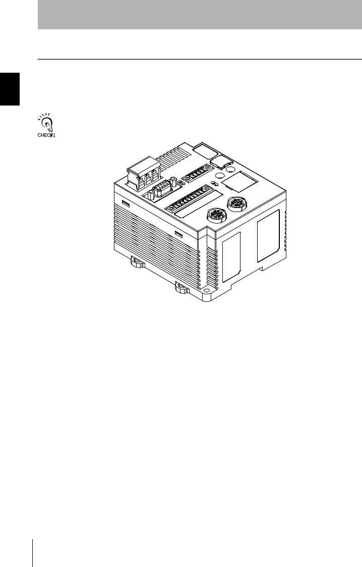
Part Names and Functions
Part Names
V680-CA5D01-V2
Controller Number Switches |
Main Indicators |
|
Switch Cover |
USB Port |
|
|
Monitor display |
|
Bar Indicator |
RS-422/RS-485 Port |
Mode Switch |
|
Antenna Port |
Terminating Resistance Switch |
|
Power Supply Terminals |
|
|
Antenna Operation Indicators |
Ground Terminal |
External I/O Port |
|
|
RS-232C Port |
|
Functions and Names Part 1 SECTION
V680-CA5D02-V2
Controller Number Switches Main Indicators
|
Switch Cover |
|
USB Port |
|
|
|
Monitor display |
|
RS-422/RS-485 Port |
Bar Indicator |
|
Mode Switch |
||
|
||
Terminating Resistance Switch |
Antenna Port |
|
|
||
Power Supply Terminals |
Antenna Operation |
|
|
||
|
Indicators |
|
Ground Terminal |
External I/O Port |
|
|
||
|
RS-232C Port |
RFID System
User’s Manual 13

Functions and Names Part 1 SECTION
SECTION 1
Product Overview
Power Supply and Ground Terminals
Description |
Description |
|
|
Power supply terminals |
Supply 24 VDC power to these terminals. |
|
Recommended power supply: OMRON S8VS-03024. |
|
|
Ground terminal |
The ground terminal. Connect this terminal to an independent ground line connected to 100 Ω. or |
|
less. |
|
|
External I/O Port
The external I/O port is used to connect external I/O signals.
There are two external I/O signal arrangements that can be used for the same port: the same signal arrangement as the V600-CA5D@@ and a signal arrangement unique to the V680-CA5D@@-V2. The desired I/O signal arrangement can be specified using the PARAMETER SET (SP) command. In Self-execution Mode, the use of ports other than RUN and RST can be set.
Description |
Description |
||
|
|
||
V600 I/O |
V680 I/O |
||
|
|||
|
|
|
|
RUN |
|
Turns ON when the ID Controller is operating normally and the communications are possible with the |
|
|
|
host device. |
|
|
|
|
|
BUSY |
OUT3 |
BUSY: Output from when a tag communications command is received from the host device until tag |
|
|
|
communications have been completed. This is the default setting. |
|
|
|
OUT3: User output 3. This output can be controlled with the CONTROLLER CONTROL (CC) com- |
|
|
|
mand. |
|
|
|
|
|
ERROR |
OUT4 |
ERROR: Output for 500 ms when a tag communications error, host communications error, or hard- |
|
|
|
ware error has occurred. The output time can be changed with the PARAMETER SET (SP) |
|
|
|
command. This is the default setting. |
|
|
|
OUT4: User output 4. This output can be controlled with the CONTROLLER CONTROL (CC) com- |
|
|
|
mand. |
|
|
|
|
|
OUT1 |
|
OUT1: User output 1. This output can be controlled with the CONTROLLER CONTROL (CC) com- |
|
|
|
mand. |
|
|
|
|
|
OUT2 |
|
OUT2: User output 2. This output can be controlled with the CONTROLLER CONTROL (CC) com- |
|
|
|
mand. |
|
|
|
|
|
COM_O |
|
Common terminal for outputs. |
|
|
|
|
|
RST |
|
External reset input for emergency stops. The ID Controller is reset when an input is received. |
|
|
|
|
|
TRG1 |
|
V680 Command System |
|
|
|
If a trigger communications designation (SI, RI, or PI) is specified, the command received by Antenna |
|
|
|
1 will be executed on the rising edge of the TRG1 input. If any other communications designation is |
|
|
|
specified, TRG1 is used as user input 1, which can be read using the CONTROLLER CONTROL |
|
|
|
(CC) command. |
|
|
|
V600 Command System |
|
|
|
If pin 6 on DIP switch SW4 (Lower Trigger Execution Setting) is turned ON, any command already |
|
|
|
received by Antenna 1 will be executed on the rising edge of the TRG1 Input. If pin 6 is turned OFF, |
|
|
|
TRG1 is used as user input 1, which can be read using the CONTROLLER CONTROL (CC) com- |
|
|
|
mand. |
|
|
|
|
|
TRG2 |
|
V680 Command System |
|
|
|
If a trigger communications designation (SI, RI, or PI) is specified, the command received by Antenna |
|
|
|
2 will be executed on the rising edge of the TRG2 input. If any other communications designation is |
|
|
|
specified, TRG2 is used as user input 2, which can be read using the CONTROLLER CONTROL |
|
|
|
(CC) command. |
|
|
|
V600 Command System |
|
|
|
If pin 6 on DIP switch SW4 (Lower Trigger Execution Setting) is turned ON, any command already |
|
|
|
received by Antenna 2 will be executed on the rising edge of the TRG2 input. If pin 6 is turned OFF, |
|
|
|
TRG2 is used as user input 2, which can be read using the CONTROLLER CONTROL (CC) com- |
|
|
|
mand. |
|
|
|
|
|
COM_I |
|
Common terminal for inputs |
|
|
|
|
|
14 |
RFID System |
User’s Manual |
|
|
|

SECTION 1
Product Overview
RS-232C Port
The RS-232C port is used to communicate with a host device. A computer, PLC, or similar host device with an RS-232C interface can be connected.
RS-422/RS-485 Port
The RS-422/RS-485 port is used to communicate with a host device. Computers, PLCs, and similar host devices with RS-422/RS-485 interfaces can be connected.
USB Port
The USB port is used to connect to a computer via a USB cable. The port is USB 1.1. Communications with host devices using USB connections can be made using only 1:1 protocol, regardless of the setting of pin 9 on DIP switch SW3.
The USB port is not a control port. Always use the RS-232C port or RS-422/RS-485 port when building systems.
p. 19
Functions and Names Part 1 SECTION
Antenna Port
The antenna port is used to connect V680-series Amplifiers and Antennas.
Controller Number Switches
The Controller number switches are used to set the number of the ID Controller when connecting more than one ID Controller to one host device.
Refer to Controller Number Switch Settings (SW1, SW2) for details on this switch.
p. 60
Switch Cover
There are two DIP switches behind the switch cover for making settings.
Refer to DIP Switch Settings (SW3, SW4) for details on these switches.
p. 61
Mode Switch
The mode switch is used to change the ID Controller's operation mode (between Run and Maintenance Mode).
Refer to Mode Switch Setting for details on this switch.
p. 63
Terminating Resistance Switch
This switch can be use to connect or disconnect the internal terminating resistance.
Refer to Terminating Resistance for details on this switch.
p. 63
RFID System
User’s Manual 15

Functions and Names Part 1 SECTION
SECTION 1
Product Overview
Main Indicators
Indicator |
Color |
Description |
|
|
|
RUN/RST |
Green |
Lit while the ID Controller is operating normally. |
|
|
|
|
Red |
Lit while external reset signal is being input. |
|
|
|
COMM |
Green |
Lit during normal communications with a host device. |
|
|
|
|
Red |
Lit when an error is detected for communications with a host device. |
|
|
|
Antenna Operation Indicators
Indicator |
Color |
Description |
|
|
|
|
|
COMM1 |
Yellow |
Lit during processing of commands for Tag communications by Antenna 1. |
|
|
|
|
|
NORM1/ |
Green |
Lights once upon normal completion of processing by Antenna 1. |
|
ERR1 |
|
|
|
Red |
Lights once when processing ends in an error at Antenna 1. |
||
|
|||
|
|
|
|
COMM2 |
Yellow |
Lit during processing of commands for communications with Tags by Antenna 2. |
|
(See note.) |
|
||
|
|
||
|
|
|
|
NORM2/ |
Green |
Lights once upon normal completion of processing by Antenna 2. |
|
ERR2 |
|
|
|
Red |
Lights once when processing ends in an error at Antenna 2. |
||
(See note.) |
|||
|
|||
|
|
||
|
|
|
Note: The V680-CA5D01-V2 does not have COMM2 or NORM2/ERR2 indicators.
Monitor Display
Indicator |
Color |
|
Mode |
Description |
|
|
|
|
|
7-segment |
Red |
Run Mode |
Command Execution |
Displays end codes. |
display |
|
|
Mode |
|
(2 digits) |
|
|
|
|
|
|
Self-execution Mode |
|
|
|
|
|
|
|
|
|
|
|
|
|
|
Maintenance |
Distance Level Measure- |
Converts and measures the Antenna output at six levels. |
|
|
Mode |
ment Mode |
The level is displayed as either “EE” or 01 to 06. |
|
|
|
|
“--” will be displayed if there is no Tag in the Antenna’s com- |
|
|
|
|
munications area. |
|
|
|
|
|
|
|
|
Tag Communications |
Communicates with Tags and displays end codes. |
|
|
|
Test Mode |
p. 147 |
|
|
|
|
|
|
|
|
Speed Level Measure- |
Repeatedly communicates with moving Tags and displays |
|
|
|
ment Mode (read/write) |
the number of successful communications between 01 and |
|
|
|
|
99. The display will show 99 even if more than 99 success- |
|
|
|
|
ful communications were made. |
|
|
|
|
“EE” will be displayed if the first communication after the |
|
|
|
|
Tag entered the communications area fails. |
|
|
|
|
|
|
|
|
Noise Level Measure- |
Displays the ambient noise level between 00 and 99. |
|
|
|
ment Mode |
|
|
|
|
|
|
|
|
|
Communications Suc- |
Communicates 100 times with a Tag with no retries, and |
|
|
|
cess Rate Measurement |
displays the communications success rate between 01 and |
|
|
|
Mode |
99 (%). If no communications were successful, “EE” is dis- |
|
|
|
|
played. If all communications were successful, “FF” is dis- |
|
|
|
|
played. |
|
|
|
|
|
16 |
RFID System |
User’s Manual |
|
|
|
SECTION 1
Product Overview
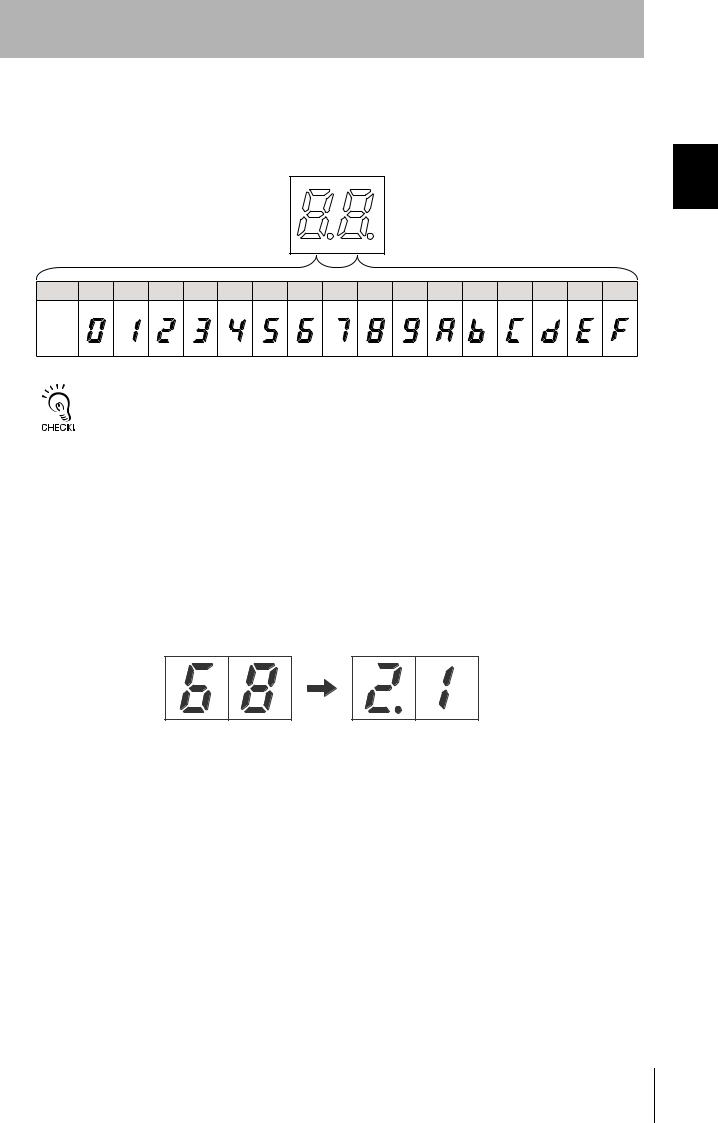
Run Mode (SW5 OFF)
In Run Mode, the end codes for command processing is displayed. The end code is displayed in 2-digit
hexadecimal, as shown below.
The display is lit for normal and warning responses and flashes for error responses.
Hexa- |
0 |
1 |
2 |
3 |
4 |
5 |
6 |
7 |
8 |
9 |
A |
B |
C |
D |
E |
F |
|
decimal |
|||||||||||||||||
|
|
|
|
|
|
|
|
|
|
|
|
|
|
|
|
||
Display |
|
|
|
|
|
|
|
|
|
|
|
|
|
|
|
|
The error code “15” will be displayed if the operation conditions have not been set and operation is switched to
Self-execution Mode.
Maintenance Mode (SW5 ON)
In Maintenance Mode, the measurement results for each measurement mode is displayed in 2-digit decimal.
Checking the Version
The version can be checked on the monitor display when turning ON the power.
Checking Method (example shows version 2.1)
1.Turn ON the power for the V680-CA5D0@-V2.
2.The following appears on the monitor display.
Functions and Names Part 1 SECTION
Bar Indicator
Indicator |
Color |
|
Description |
|
|
|
|
|
|
1 |
Yellow |
The Antenna and the Tag are far apart. |
|
The Tag travel speed is fast. |
|
|
↑ |
|
↑ |
2 |
Yellow |
|
||
|
|
| |
|
| |
3 |
Yellow |
|
||
|
|
| |
|
| |
4 |
Yellow |
|
||
|
|
↓ |
|
↓ |
5 |
Yellow |
|
||
|
|
|
|
|
6 |
Yellow |
The Antenna and Tag are close. |
|
The Tag travel speed is slow. |
|
|
|
|
|
RFID System
User’s Manual 17
SECTION 1
Product Overview
Functions and Names Part 1 SECTION
18 |
RFID System |
User’s Manual |
|
|
|
 Bar Indicator
1 6
SECTION 1
Product Overview
System Configuration
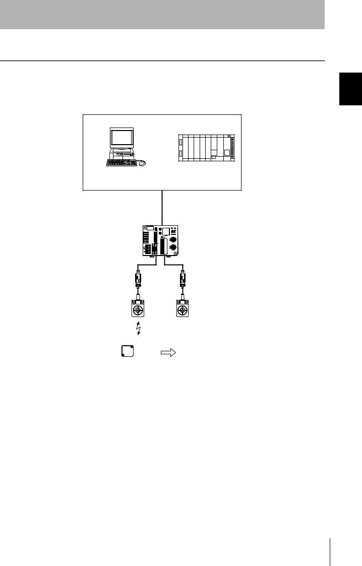
 1:1 Connection
One host device is connected via the RS-232C, RS-422, or RS-485 interface.
• Using an Antenna Other than the V680-H01
Personal computer |
Programmable Controller |
|
(PLC) |
||
|
RS-232C, RS-422, or
RS-485 interface
ID Controller
V680-CA5D01-V2
V680-CA5D02-V2
Amplifiers
V680-HA63 A/B
Antennas
V680-HS52
V680-HS63
V680-HS65
V680-HS51
|
|
|
|
|
|
|
|
|
|
|
|
|
|
|
|
|
|
|
|
|
Tag |
Pallet or other object |
||
Configuration System 1 SECTION
RFID System
User’s Manual 19

Configuration System 1 SECTION
SECTION 1
Product Overview
• Using a V680-H01 Antenna
Personal computer |
Programmable Controller |
|
(PLC) |
||
|
RS-232C, RS-422, or
RS-485 interface
ID Controller
V680-CA5D01-V2
Antennas
V680-H01
Tag |
Pallet or other object |
The V680-H01 Antenna can be connected only to the V680-CA5D01-V2 ID Controller. It cannot be used with the V680-
CA5D02-V2 ID Controller
20 |
RFID System |
User’s Manual |
|
|
|

SECTION 1
Product Overview
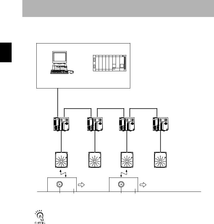
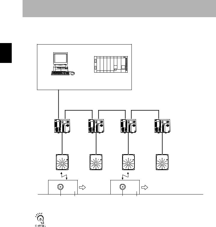
 1:N Connections with RS-232C Connection to Host Device
The host device can be connected via RS-232C and then other ID Controllers can be connected via
RS-422/RS-485 interfaces.
• Using an Antenna Other than the V680-H01
Personal computer |
Programmable Controller |
|
(PLC) |
||
|
RS-232C
RS-422/RS-485 |
|
RS-422/RS-485 |
|
RS-422/RS-485 |
|
|
|
|
|
ID Controller
V680-CA5D01-V2
V680-CA5D02-V2
 Amplifiers
V680-HA63 A/B
Antennas
V680-HS52
V680-HS63
V680-HS65
V680-HS51
Tag |
Pallet or other object |
Tag |
Pallet or other object |
Configuration System 1 SECTION
RFID System
User’s Manual 21
Configuration System 1 SECTION
SECTION 1
Product Overview
• Using a V680-H01 Antenna
Personal computer |
Programmable Controller |
|
(PLC) |
||
|
RS-232C
RS-422/RS-485 |
RS-422/RS-485 |
RS-422/RS-485 |
ID Controller
V680-CA5D01-V2
Antennas
V680-H01
Tag |
Pallet or other object |
Tag |
Pallet or other object |
The V680-H01 Antenna can be connected only to the V680-CA5D01-V2 ID Controller. It cannot be used with the V680-
CA5D02-V2 ID Controller
22 |
RFID System |
User’s Manual |
|
|
|

SECTION 1
Product Overview
 1:N Connections with RS-422/RS-485 Connection to Host Device
The host device and other ID Controllers can all be connected via RS-422 or RS-485 interfaces.
• Using an Antenna Other than the V680-H01
Personal computer |
Programmable Controller |
|
(PLC) |
||
|
RS-422/RS-485
RS-422/RS-485 |
|
RS-422/RS-485 |
|
RS-422/RS-485 |
|
|
|
|
|
|
|
|
|
|
ID Controller
V680-CA5D01-V2
V680-CA5D02-V2
 Amplifiers
V680-HA63 A/B
Antennas
V680-HS52
V680-HS63
V680-HS65
V680-HS51
Tag |
Pallet or other object |
Tag |
Pallet or other object |
Configuration System 1 SECTION
RFID System
User’s Manual 23
Configuration System 1 SECTION
SECTION 1
Product Overview
• Using a V680-H01 Antenna
Personal computer |
Programmable Controller |
|
(PLC) |
||
|
RS-422/RS-485
RS-422/RS-485 |
RS-422/RS-485 |
RS-422/RS-485 |
ID Controller
V680-CA5D01-V2
Antennas
V680-H01
Tag |
Pallet or other object |
Tag |
Pallet or other object |
The V680-H01 Antenna can be connected only to the V680-CA5D01-V2 ID Controller. It cannot be used with the V680-
CA5D02-V2 ID Controller
24 |
RFID System |
User’s Manual |
|
|
|
SECTION 1
Product Overview
Application Flowchart
|
|
|
|
|
|
|
|
|
|
|
|
|
|
|
|
|
|
|
|
|
|
|
|
|
|
|
Install the system. |
|
|
|
Preparation |
|
p. 28 |
|
|
|
|
|
|
|
|
|
|
|
|
|
|
|
Connect the system. |
|
|
||
|
|
|
p. 30 |
|
|
|
|
|
|
|
|
|
|
|
|
|
|
preparation |
|
|
|
Set the ID Controller's communications conditions. |
|
||
Communications |
|
p. 58 |
|
|
|
|
|
|
|
|
|
|
|
|
|
Perform a communications test between the ID Controller and host device.

 p. 77
p. 77
operation |
|
p. 78. |
|
|
Perform a communications test between the Tags and Antennas. |
Trial |
|
|
|
|
|
|
Check the ambient environment. |
|
p. 245 |
|
|
Communications |
|
|
|
Perform actual communications using commands. |
|
||
|
|
|
|
|
|
p. 97 |
|
|
|
|
|
|
|
|
|
Flowchart Application 1 SECTION
RFID System
User’s Manual 25

SECTION 1
Product Overview
MEMO
Flowchart Application 1 SECTION
26 |
RFID System |
User’s Manual |

SECTION 2
Installation, Connections, and Wiring
|
|
Installation |
28 |
|
|
|
|
|
|
Connection and Wiring |
30 |
|
|
||
|
|
|
|
RFID System
User’s Manual
Wiring and Connections, Installation, 2 SECTION
27
Loading...