


 Loading...
NT-series
NT20M/NT600M Support Tool
Operation Manual
Revised August 1993
Notice:
OMRON products are manufactured for use according to proper procedures by a qualified operator and only for the purposes described in this manual.
The following conventions are used to indicate and classify precautions in this manual. Always heed the information provided with them. Failure to head precautions can result in injury to people or damage to the product.
DANGER! Indicates information that, if not heeded, is likely to result in loss of life or serious injury.
WARNING Indicates information that, if not heeded, could possibly result in loss of life or serious injury.
Caution Indicates information that, if not heeded, could result in relative serious or minor injury, damage to the product, or faulty operation.
OMRON Product References
All OMRON products are capitalized in this manual. The word ªUnitº is also capitalized when it refers to an OMRON product, regardless of whether or not it appears in the proper name of the product.
The abbreviation ªCh,º which appears in some displays and on some OMRON products, often means ªwordº and is abbreviated ªWdº in documentation in this sense.
The abbreviation ªPCº means Programmable Controller and is not used as an abbreviation for anything else.
Visual Aids
The following headings appear in the left column of the manual to help you locate different types of information.
Note Indicates information of particular interest for efficient and convenient operation of the product.
1, 2, 3... Indicates lists of one sort or another, such as procedures, precautions, etc.
OMRON, 1991
All rights reserved. No part of this publication may be reproduced, stored in a retrieval system, or transmitted, in any form, or by any means, mechanical, electronic, photocopying, recording, or otherwise, without the prior written permission of OMRON.
No patent liability is assumed with respect to the use of the information contained herein. Moreover, because OMRON is constantly striving to improve its high-quality products, the information contained in this manual is subject to change without notice. Every precaution has been taken in the preparation of this manual. Nevertheless, OMRON assumes no responsibility for errors or omissions. Neither is any liability assumed for damages resulting from the use of the information contained in this publication.
v
TABLE OF CONTENTS
SECTION 1 |
|
|
Introduction . . . . . . . . . . . . . . . . . . . . . . . . . . . . . . . . . . . . . |
1 |
|
1-1 |
Terminology and NT-series Manuals . . . . . . . . . . . . . . . . . . . . . . . . . . . . . . . . . . . . . . . . . . |
2 |
1-2 |
Using Older Models . . . . . . . . . . . . . . . . . . . . . . . . . . . . . . . . . . . . . . . . . . . . . . . . . . . . . . . |
2 |
1-3 |
System Configuration . . . . . . . . . . . . . . . . . . . . . . . . . . . . . . . . . . . . . . . . . . . . . . . . . . . . . . |
3 |
1-4 |
Creating a Work Disk . . . . . . . . . . . . . . . . . . . . . . . . . . . . . . . . . . . . . . . . . . . . . . . . . . . . . . |
4 |
1-5 |
Starting and Exiting . . . . . . . . . . . . . . . . . . . . . . . . . . . . . . . . . . . . . . . . . . . . . . . . . . . . . . . |
5 |
1-6 |
Main Menu . . . . . . . . . . . . . . . . . . . . . . . . . . . . . . . . . . . . . . . . . . . . . . . . . . . . . . . . . . . . . . |
5 |
1-7 |
File Selection . . . . . . . . . . . . . . . . . . . . . . . . . . . . . . . . . . . . . . . . . . . . . . . . . . . . . . . . . . . . |
6 |
1-8 |
Screen Selection . . . . . . . . . . . . . . . . . . . . . . . . . . . . . . . . . . . . . . . . . . . . . . . . . . . . . . . . . . |
7 |
1-9 |
Inputting Screen Comments, File Names, and Titles . . . . . . . . . . . . . . . . . . . . . . . . . . . . . . |
10 |
1-10 |
Editing Screens . . . . . . . . . . . . . . . . . . . . . . . . . . . . . . . . . . . . . . . . . . . . . . . . . . . . . . . . . . . |
11 |
1-11 |
Inputting Character Strings and Numbers . . . . . . . . . . . . . . . . . . . . . . . . . . . . . . . . . . . . . . |
12 |
1-12 |
Basic Operation . . . . . . . . . . . . . . . . . . . . . . . . . . . . . . . . . . . . . . . . . . . . . . . . . . . . . . . . . . |
13 |
1-13 |
Tool Settings . . . . . . . . . . . . . . . . . . . . . . . . . . . . . . . . . . . . . . . . . . . . . . . . . . . . . . . . . . . . . |
15 |
1-14 |
Environment Settings . . . . . . . . . . . . . . . . . . . . . . . . . . . . . . . . . . . . . . . . . . . . . . . . . . . . . . |
16 |
1-15 |
Direct Connection . . . . . . . . . . . . . . . . . . . . . . . . . . . . . . . . . . . . . . . . . . . . . . . . . . . . . . . . |
17 |
SECTION 2 |
|
|
Creating Screens . . . . . . . . . . . . . . . . . . . . . . . . . . . . . . . . . |
21 |
|
2-1 |
Inputting Character Strings . . . . . . . . . . . . . . . . . . . . . . . . . . . . . . . . . . . . . . . . . . . . . . . . . |
22 |
2-2 |
Numeral Displays . . . . . . . . . . . . . . . . . . . . . . . . . . . . . . . . . . . . . . . . . . . . . . . . . . . . . . . . . |
28 |
2-3 |
Character String Displays . . . . . . . . . . . . . . . . . . . . . . . . . . . . . . . . . . . . . . . . . . . . . . . . . . . |
34 |
2-4 |
Lamps . . . . . . . . . . . . . . . . . . . . . . . . . . . . . . . . . . . . . . . . . . . . . . . . . . . . . . . . . . . . . . . . . . |
40 |
2-5 |
Touch Switches . . . . . . . . . . . . . . . . . . . . . . . . . . . . . . . . . . . . . . . . . . . . . . . . . . . . . . . . . . |
46 |
2-6 |
Bar Graphs . . . . . . . . . . . . . . . . . . . . . . . . . . . . . . . . . . . . . . . . . . . . . . . . . . . . . . . . . . . . . . |
51 |
2-7 |
Editing Memory Tables . . . . . . . . . . . . . . . . . . . . . . . . . . . . . . . . . . . . . . . . . . . . . . . . . . . . |
59 |
2-8 |
Numeral Editing . . . . . . . . . . . . . . . . . . . . . . . . . . . . . . . . . . . . . . . . . . . . . . . . . . . . . . . . . . |
62 |
2-9 |
Polylines . . . . . . . . . . . . . . . . . . . . . . . . . . . . . . . . . . . . . . . . . . . . . . . . . . . . . . . . . . . . . . . . |
71 |
2-10 |
Circles . . . . . . . . . . . . . . . . . . . . . . . . . . . . . . . . . . . . . . . . . . . . . . . . . . . . . . . . . . . . . . . . . . |
73 |
2-11 |
Continuous and Overlapping Screens . . . . . . . . . . . . . . . . . . . . . . . . . . . . . . . . . . . . . . . . . |
75 |
2-12 |
Screen Attributes . . . . . . . . . . . . . . . . . . . . . . . . . . . . . . . . . . . . . . . . . . . . . . . . . . . . . . . . . |
78 |
2-13 |
Screen Check . . . . . . . . . . . . . . . . . . . . . . . . . . . . . . . . . . . . . . . . . . . . . . . . . . . . . . . . . . . . |
80 |
2-14 |
Marks . . . . . . . . . . . . . . . . . . . . . . . . . . . . . . . . . . . . . . . . . . . . . . . . . . . . . . . . . . . . . . . . . . |
82 |
2-15 |
Stand-alone Operation . . . . . . . . . . . . . . . . . . . . . . . . . . . . . . . . . . . . . . . . . . . . . . . . . . . . . |
85 |
2-16 |
Edit . . . . . . . . . . . . . . . . . . . . . . . . . . . . . . . . . . . . . . . . . . . . . . . . . . . . . . . . . . . . . . . . . . . . |
87 |
SECTION 3 |
|
|
Managing Screen Data . . . . . . . . . . . . . . . . . . . . . . . . . . . . |
89 |
|
3-1 |
Copying Screens . . . . . . . . . . . . . . . . . . . . . . . . . . . . . . . . . . . . . . . . . . . . . . . . . . . . . . . . . . |
90 |
3-2 |
Deleting Screens . . . . . . . . . . . . . . . . . . . . . . . . . . . . . . . . . . . . . . . . . . . . . . . . . . . . . . . . . . |
91 |
3-3 |
Changing Screen Comments . . . . . . . . . . . . . . . . . . . . . . . . . . . . . . . . . . . . . . . . . . . . . . . . |
92 |
3-4 |
Reading Data from Other Files . . . . . . . . . . . . . . . . . . . . . . . . . . . . . . . . . . . . . . . . . . . . . . |
93 |
SECTION 4 |
|
|
Managing File Data . . . . . . . . . . . . . . . . . . . . . . . . . . . . . . . |
95 |
|
4-1 |
Copying Files . . . . . . . . . . . . . . . . . . . . . . . . . . . . . . . . . . . . . . . . . . . . . . . . . . . . . . . . . . . . |
96 |
4-2 |
Deleting Files . . . . . . . . . . . . . . . . . . . . . . . . . . . . . . . . . . . . . . . . . . . . . . . . . . . . . . . . . . . . |
97 |
4-3 |
Changing File Titles . . . . . . . . . . . . . . . . . . . . . . . . . . . . . . . . . . . . . . . . . . . . . . . . . . . . . . . |
98 |
4-4 |
Saving PT Histories in Files . . . . . . . . . . . . . . . . . . . . . . . . . . . . . . . . . . . . . . . . . . . . . . . . . |
98 |
4-5 |
Setting Initial Screens . . . . . . . . . . . . . . . . . . . . . . . . . . . . . . . . . . . . . . . . . . . . . . . . . . . . . |
99 |
vii
SECTION 5 |
|
|
Printing . . . . . . . . . . . . . . . . . . . . . . . . . . . . . . . . . . . . . . . . . |
101 |
|
5-1 |
Printing Features . . . . . . . . . . . . . . . . . . . . . . . . . . . . . . . . . . . . . . . . . . . . . . . . . . . . . . . . . |
102 |
5-2 Printing from the File Selection Display . . . . . . . . . . . . . . . . . . . . . . . . . . . . . . . . . . . . . . . |
102 |
|
5-3 Printing from the Screen Selection Display . . . . . . . . . . . . . . . . . . . . . . . . . . . . . . . . . . . . . |
103 |
|
SECTION 6 |
|
|
Transmitting Data . . . . . . . . . . . . . . . . . . . . . . . . . . . . . . . . |
105 |
|
6-1 Connecting to the PT . . . . . . . . . . . . . . . . . . . . . . . . . . . . . . . . . . . . . . . . . . . . . . . . . . . . . . |
106 |
|
6-2 |
Transmitting Data . . . . . . . . . . . . . . . . . . . . . . . . . . . . . . . . . . . . . . . . . . . . . . . . . . . . . . . . . |
106 |
6-3 |
Receiving Data . . . . . . . . . . . . . . . . . . . . . . . . . . . . . . . . . . . . . . . . . . . . . . . . . . . . . . . . . . . |
110 |
6-4 |
Deleting PT Screens . . . . . . . . . . . . . . . . . . . . . . . . . . . . . . . . . . . . . . . . . . . . . . . . . . . . . . . |
114 |
SECTION 7 |
|
|
PROM Writer Operations . . . . . . . . . . . . . . . . . . . . . . . . . |
117 |
|
7-1 Connecting to a PROM Writer . . . . . . . . . . . . . . . . . . . . . . . . . . . . . . . . . . . . . . . . . . . . . . . |
118 |
|
7-2 Transmitting Data to a PROM Writer . . . . . . . . . . . . . . . . . . . . . . . . . . . . . . . . . . . . . . . . . |
118 |
|
7-3 Transmitting Data with Verification to a PROM Writer . . . . . . . . . . . . . . . . . . . . . . . . . . . |
119 |
|
7-4 Receiving Data from a PROM Writer . . . . . . . . . . . . . . . . . . . . . . . . . . . . . . . . . . . . . . . . . |
120 |
|
Appendix: Special Characters . . . . . . . . . . . . . . . . . . . . . . |
123 |
|
Index . . . . . . . . . . . . . . . . . . . . . . . . . . . . . . . . . . . . . . . . . . . |
125 |
|
Revision History . . . . . . . . . . . . . . . . . . . . . . . . . . . . . . . . . |
127 |
|
viii
About this Manual:
This manual describes the installation and operation of the Support Tool and includes the sections described below. The Support Tool is a software package for creating and managing displays for the NT20M and NT600M Programmable Terminals (PTs).
Please read this manual completely and be sure you understand the information provided before attempting to install and operation the Support Tool.
Section 1 provides an overview of Support Tool operation and its operating environment. Basic operating and input methods common to most Support Tool features are covered. The last section, Tool Settings, describes how to set Support Tool operating parameters, which affect overall operation.
Section 2 describes the specific operations used to create displays for Programmable Terminals. Special features include numeral displays, character string displays, lamps, and bar graphs, all of which can be used to display on-screen data transferred to the PT from the PT's host, and numeral editing and touch switches, both of which can be used to input data on-screen for transfer to the host from the PT.
Section 3 describes how to manage screens as whole units.
Section 4 describes how to manage files.
Section 5 describes how to print screen images.
Section 6 describes the setup and methods for transferring data between the Support Tool and the PT. This section also includes remote operations for deleting screens from the PT.
Section 7 describes the setup and methods for transferring data between the Support Tool and a PROM writer.
The Appendix provides a table of English character codes.
WARNING Failure to read and understand the information provided in this manual may result in personal injury or death, damage to the product, or product failure. Please read each section in its entirety and be sure you understand the information provided in the section and related sections before attempting any of the procedures or operations given.
ix
SECTION 1
Introduction
This section outlines the operations of the Support Tool. It includes general operating procedures and installation procedures, as well as miscellaneous information, such as the functional limitations when creating screens for older PT models. Refer to the other sections in this manual for details on specific operations. Reference pages are given in this section for many operations.
1-1 |
Terminology and NT-series Manuals . . . . . . . . . . . . . . . . . . . . . . . . . . . . . . . . . . . . . . . . . . |
2 |
|
1-2 |
Using Older Models . . . . . . . . . . . . . . . . . . . . . . . . . . . . . . . . . . . . . . . . . . . . . . . . . . . . . . . |
2 |
|
1-3 |
System Configuration . . . . . . . . . . . . . . . . . . . . . . . . . . . . . . . . . . . . . . . . . . . . . . . . . . . . . . |
3 |
|
|
1-3-1 |
NT20M and NT600M Support Tool Operations . . . . . . . . . . . . . . . . . . . . . . . . . . |
3 |
|
1-3-2 |
Menu Configuration . . . . . . . . . . . . . . . . . . . . . . . . . . . . . . . . . . . . . . . . . . . . . . . . |
3 |
|
1-3-3 |
Support Tool System . . . . . . . . . . . . . . . . . . . . . . . . . . . . . . . . . . . . . . . . . . . . . . . |
4 |
1-4 |
Creating a Work Disk . . . . . . . . . . . . . . . . . . . . . . . . . . . . . . . . . . . . . . . . . . . . . . . . . . . . . . |
4 |
|
1-5 |
Starting and Exiting . . . . . . . . . . . . . . . . . . . . . . . . . . . . . . . . . . . . . . . . . . . . . . . . . . . . . . . |
5 |
|
1-6 |
Main Menu . . . . . . . . . . . . . . . . . . . . . . . . . . . . . . . . . . . . . . . . . . . . . . . . . . . . . . . . . . . . . . |
5 |
|
1-7 |
File Selection . . . . . . . . . . . . . . . . . . . . . . . . . . . . . . . . . . . . . . . . . . . . . . . . . . . . . . . . . . . . |
6 |
|
1-8 |
Screen Selection . . . . . . . . . . . . . . . . . . . . . . . . . . . . . . . . . . . . . . . . . . . . . . . . . . . . . . . . . . |
7 |
|
1-9 |
Inputting Screen Comments, File Names, and Titles . . . . . . . . . . . . . . . . . . . . . . . . . . . . . . |
10 |
|
|
1-9-1 |
Screen Comments . . . . . . . . . . . . . . . . . . . . . . . . . . . . . . . . . . . . . . . . . . . . . . . . . |
10 |
|
1-9-2 |
File Names and Titles . . . . . . . . . . . . . . . . . . . . . . . . . . . . . . . . . . . . . . . . . . . . . . |
10 |
1-10 |
Editing Screens . . . . . . . . . . . . . . . . . . . . . . . . . . . . . . . . . . . . . . . . . . . . . . . . . . . . . . . . . . . |
11 |
|
1-11 |
Inputting Character Strings and Numbers . . . . . . . . . . . . . . . . . . . . . . . . . . . . . . . . . . . . . . |
12 |
|
1-12 |
Basic Operation . . . . . . . . . . . . . . . . . . . . . . . . . . . . . . . . . . . . . . . . . . . . . . . . . . . . . . . . . . |
13 |
|
|
1-12-1 Cursors . . . . . . . . . . . . . . . . . . . . . . . . . . . . . . . . . . . . . . . . . . . . . . . . . . . . . . . . . . |
13 |
|
|
1-12-2 |
Screen Buttons . . . . . . . . . . . . . . . . . . . . . . . . . . . . . . . . . . . . . . . . . . . . . . . . . . . . |
14 |
|
1-12-3 Mouse . . . . . . . . . . . . . . . . . . . . . . . . . . . . . . . . . . . . . . . . . . . . . . . . . . . . . . . . . . . |
14 |
|
|
1-12-4 |
Positioning Operations . . . . . . . . . . . . . . . . . . . . . . . . . . . . . . . . . . . . . . . . . . . . . . |
14 |
1-13 |
Tool Settings . . . . . . . . . . . . . . . . . . . . . . . . . . . . . . . . . . . . . . . . . . . . . . . . . . . . . . . . . . . . . |
15 |
|
1-14 |
Environment Settings . . . . . . . . . . . . . . . . . . . . . . . . . . . . . . . . . . . . . . . . . . . . . . . . . . . . . . |
16 |
|
1-15 |
Direct Connection . . . . . . . . . . . . . . . . . . . . . . . . . . . . . . . . . . . . . . . . . . . . . . . . . . . . . . . . |
17 |
|
|
1-15-1 |
Specifying PC Addresses for Direct Connection . . . . . . . . . . . . . . . . . . . . . . . . . . |
18 |
|
1-15-2 |
Direct Connection Information . . . . . . . . . . . . . . . . . . . . . . . . . . . . . . . . . . . . . . . |
19 |
1

Using Older Models Section 1-2
1-1 |
Terminology and NT-series Manuals |
||
|
|
Names of items in this manual related to the NT Series of Programmable Ter- |
|
|
|
minals and SYSMAC C-series Programmable Controllers are defined next. |
|
Abbreviations |
The following abbreviations are used in the text. |
||
|
|
|
|
Abbreviation |
Term |
Meaning |
|
|
|
|
|
PT |
|
Programmable Terminal |
Refers to an OMRON NT-series Programmable Terminal. |
|
|
|
|
PC |
|
Programmable |
Refers to an OMRON SYSMAC C-series or CV-series Programmable |
|
|
Controller |
Controller, or programmable controllers manufactured by other companies. |
|
|
|
|
I/F |
|
interface |
A communications device that connects the Programmable Terminal with |
|
|
|
peripheral devices. |
|
|
|
|
I/O |
|
input/output |
Refers to PT and PC inputs and outputs. |
SYSMAC Terminology
Terminology |
Explanation |
|
|
SYSMAC |
A generic name for OMRON's Programmable Controllers. |
|
|
Host Link System |
A system employing SYSMAC C-series Host Link Units used to create a communications bus |
(SYSMAC WAY) |
between PCs, between PCs and PTs, etc. |
|
|
SYSMAC BUS |
A remote I/O network created between SYSMAC C-series PCs and input/output devices. |
Reference Manuals |
The NT20M/NT2000M Series and NT600M Series are covered in the six |
|
|
manuals described below. Actual manual numbers also include suffixes indi- |
|
|
cating the version of the manual. |
|
|
|
|
Name of Manual |
Contents |
Manual No. |
|
|
|
NT20M/NT2000M Operation |
This manual provides specifications, functions, and operating |
V001 |
Manual |
instructions for the NT20M and NT2000M Programmable Terminals. |
|
|
|
|
NT600M Operation Manual |
This manual provides specifications, functions, and operating |
V002 |
|
instructions for NT600M Programmable Terminals. |
|
|
|
|
NT-series Host Interface Unit |
This manual covers the commands, controls, and communications |
V003 |
Operation Manual |
specifications for operating the NT20M and the NT600M. Refer to |
|
|
this manual when programming host computer communications. |
|
|
|
|
NT20M/NT600M Support Tool |
This manual covers methods for creating screens, including screen |
V004 |
Operation Manual |
data preparation, switches, lights, and alarms. |
|
|
|
|
NT-series Host Interface Unit |
This manual covers the Direct Connection feature which has been |
V015 |
Direct Operation Manual |
added to the Host Interface Unit. |
|
|
|
|
NT-series RS-232C/RS-422 |
This manual covers the commands, controls, and communications |
V016 |
Interface Unit Operation Manual |
specifications for operating the NT20M and the NT600M with the |
|
|
RS-232C/RS-422 Interface Unit. Refer to this manual when |
|
|
programming host computer communications. |
|
1-2 Using Older Models
The NT Series of Programmable Terminals is constantly being improved to better serve the needs of our customers. This manual describes features available for the newest PTs. Not all of these features are available with previous versions of the Host Interface Units and System ROM, as shown in the following table. Refer to your PT's operation manuals for details on limitations when using older models.
2

System Configuration |
|
Section 1-3 |
|
|
|
|
|
Host Interface Unit and/or |
|
Unsupported features |
|
System ROM |
|
|
|
|
|
|
|
Host Interface Units |
Lamps and touch switches |
Lamp flashing for bit input designations |
|
NT20M-LK201-EV1 |
|
Round lamp displays |
|
NT20M-LK202-EV1 |
|
3D frame displays for touch switch |
|
NT20M-LK203-EV1 |
|
||
|
Reverse video display for touch switch inputs |
||
NT20M-RT121-EV1 |
|
||
|
Mark input for labels |
||
System ROM |
|
||
|
|
|
|
NT600M-SMR01-E |
Bar graphs |
Vertical displays |
|
|
|
Enlarged display widths (2 to 255 dots) |
|
|
|
+/± displays |
|
|
|
Enlarged percentage displays |
|
|
|
|
|
|
Numeral displays |
Enlarged displays |
|
|
|
Increased display quantity (50) |
|
|
|
|
|
|
Numeral tables |
Keypad layout designations |
|
|
|
Increased quantity (50) |
|
|
|
|
|
|
Stand-alone operation |
|
|
|
|
|
|
|
Backlight red/white color changes and light/flash designations |
||
1-3 System Configuration
The NT20M/NT600M Support Tool is a software package for creating and maintaining display Screens, memory tables, and custom characters (called marks) for the NT20M and NT600M Programmable Terminals. The Support Tool uses a complete system of menus to facilitate operation.
1-3-1 NT20M and NT600M Support Tool Operations
The Support Tool can be used to create and modify screens, memory tables, and marks, and save resulting data as files. Data created on the Support Tool can be transmitted to the NT20M or NT600M Programmable Terminal. In addition, the Support Tool can receive data from a Programmable Terminal, or data created on the Support Tool can be transmitted to a PROM writer. Also, the Support Tool can receive data from PROM writers. The Support Tool can read history records stored in a Programmable Terminal, and save them in files.
1-3-2 Menu Configuration
|
|
|
Edit Screen |
|
File Selection |
|
Screen |
|
Editing |
|
|
|
|
|
|
|
|
Selection |
|
|
|
|
|
|
|
|
Copy |
Copy |
Input String |
|||
|
|
|
|
|
Delete |
Delete |
Numeral Display |
|||
|
|
|
|
|
String Display |
|||||
Main Menu |
|
|
Tool Settings |
|
Title Change |
Attributes |
Lamps |
|||
|
|
|
||||||||
|
|
|
|
|
ROM |
Reading from other Files |
Touch Switches |
|||
|
|
|
See page 15 for |
History |
Table Edit |
Bar Graphs |
||||
|
|
|
specific settings. |
Transmit |
Transmit |
Table Editing |
||||
|
|
|
|
|
Receive |
Receive |
Numeral Editing |
|||
|
|
|
|
|
Initial Screen |
Continuous/Overlapping |
Graphics |
|||
|
|
|
Exit |
|
Change Capacity |
Screens |
Marks |
|||
|
|
|
|
|
Change Title |
Check |
Edit |
|||
|
|
|
|
|
Tool Settings |
Marks |
Extended Functions |
|||
|
|
|
|
|
|
Change Comment |
Environment Settings |
|||
|
|
|
|
|
|
Direct Connection Settings |
|
|
||
3

Creating a Work Disk Section 1-4
1-3-3 |
Support Tool System |
|
|
|
|
|
Model |
NT20M-ZA5AT-EV4 |
|
|
|
System disk |
|
3.5-inch (2DD) and 5-inch (2HD) disks |
|
|
|
Applicable computers |
IBM PC/AT or IBM PC/AT compatible (note 1) |
|
|
|
|
Floppy disk drives necessary |
One min. (note 2) |
|
|
|
|
Graphic monitor |
VGA |
|
|
|
|
Printer |
|
Epson dot matrix or HP laser printer |
|
|
|
PROM writer |
|
Commercially available PROM writer (note 3) |
|
|
|
Mouse |
|
Serial mouse (note 4) |
|
|
|
MS-DOS |
|
Version 3.3 or later |
Note 1. The computer must have 640 KB of memory.
2.The Support Tool can also use built-in RAM or a hard disk.
3.The following communications settings must be supported. The Intel HEX
file format can be used.
Baud rate: |
9,600 bps |
Stop bits: |
1 bit |
Data length: |
8 bits |
Parity: |
None |
4.The mouse.com file must be installed before using the Support Tool with a mouse.
1-4 Creating a Work Disk
It is recommended that you backup the Support Tool either onto floppy disks or onto your hard disk, store the originals (the floppy disks, hereafter referred to as the ªmaster disksº) and use the backup disks (hereafter referred to as the ªwork disksº) for routine work. The method for backing up onto a hard disk is explained below. If there are any points pertaining to MS-DOS which are unclear, please refer to your MS-DOS manual.
1, 2, 3... 1. Turn on the power to your computer, and start up MS-DOS.
C >
2.Insert the master disk into the floppy disk drive and switch to drive A. (Input the underlined part from the keyboard.)
C > A: 


3.Type NTINSTALspaceC:return to designate the drive onto which the Support Tool is to be installed, i.e., the work disk.
A >NTINSTAL C:
or From the A: drive, it is possible to designate the C: drive directory.
A >NTINSTAL C:\NT\ 


4.If the installation program is successfully completed, then the Support Tool will be installed in the NT directory on the work disk. Switch from the A: drive to the C: drive. In the C: drive, switch to the NT directory.
A > C: 


C >CD \NT


4
Main Menu |
|
|
|
|
|
|
Section 1-6 |
||
|
|
5. Input NTMreturn to start and use the Support Tool. |
|
||||||
|
|
C > NTM |
|||||||
|
|
|
|
|
|
|
|
|
|
|
|
This completes the backup. When starting up the next time, change directo- |
|||||||
|
|
ries to the NT directory and then input ªNTMº to start the Support Tool. |
|||||||
|
|
C >CD \NT |
|||||||
|
|
|
|
|
|
|
|
|
|
|
|
C > NTM |
|||||||
1-5 |
Starting and Exiting |
||||||||
Startup Procedure |
If working from a floppy, insert the start-up disk into disk drive A and a data |
||||||||
|
|
disk into disk drive B, then turn on the power. When using a hard disk, first |
|||||||
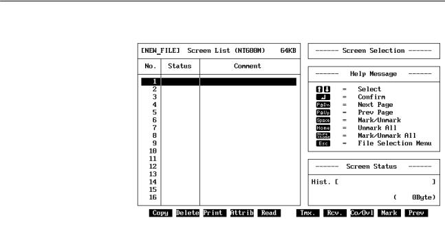
start up MS-DOS from the hard disk, then input NTMreturn from the NT directory. When the Support Tool has started, the following display will appear.
Main Menu
|
Note While the Support Tool is operating with the system disks, do not pull out the |
|
disks from the floppy disk drive or an operation error will result. |
Exiting |
While the Main Menu is displayed, use the Up Key or the Down Key to move |
|
the bar cursor to Exit, and then press the Enter Key. The MS-DOS prompt |
|
will be displayed. At this point, eject the floppy disks and turn off the power to |
|
the computer. Always be sure to follow this procedure when exiting the Sup- |
|
port Tool. |
1-6 |
Main Menu |
|
|
|
|
When you start up the Support Tool, the Main Menu will displayed and the |
|
|
|
following items will be available. |
|
Main Menu Items |
|
||
|
|
|
|
|
Item |
Function |
Page |
|
|
|
|
Edit Screen |
When you select Edit Screen from the Main Menu, you can manage files and manipulate |
15 |
|
|
|
and edit screens. |
|
|
|
|
|
Tool Settings |
With this item you select the Programmable Terminal, set the memory capacity, specify the |
11 |
|
|
|
printer to be used, and make other settings. Perform this operation first. The values that you |
|
|
|
set here are saved, so there is no need to reset them unless you want to make a change. |
|
|
|
|
|
Exit |
|
Select Exit from the Main Menu when you want to exit the Support Tool. Be sure to exit in |
5 |
|
|
this way when Support Tool operations are finished. |
|
5
File Selection |
Section 1-7 |
|
|
|
|
1-7 File Selection
When you select Edit Screen from the Main Menu, the File Selection Display is displayed. Move the bar cursor to the desired file name and press the Enter Key, or click the desired file name once to move the bar cursor and then again to open the file.
Each file contains screen data, memory table data (for numeral and character string tables), and mark data for a maximum of 250 screens for the NT20M or 1,000 screens for the NT600M. When you want to create a new file, select NEW_FILE. The Screen Selection Display will then appear to select from and a file name and title are input when returning to the File Selection Display. Refer to page 10 for name and title input procedures. If you want to modify a file that has already been created, select the file that you want to modify.
The help message area will display the direct connection setting and file size for the file indicated by the bar cursor.
Caution Check the direct connection setting before reading files. If files created with the direct connection setting turned OFF are read when the Tool Settings is set to ON, the screens will be converted to direct connection data. It is not possible to convert from direct connection data to data without direct connection.
File Selection Menu
Caution Data Compatibility with the Old Version of Software (EV1):
The EV4 version of the software can read and edit data created by the EV1. However, once the data is read by the EV4, it no longer can be read or edited by the EV1, even if the file name has not been changed. This occurs because the EV4 expands the data previously saved with the EV1.
Before using any EV1 data with the EV4, it is recommended that a backup copy of the EV1 be made.
6

Screen Selection |
Section 1-8 |
|||
File Operations |
You can perform file operations by using the function keys while the File Se- |
|
||
|
|
lection Display is being displayed. |
|
|
|
|
|
|
|
Function key |
Name |
Function |
Page |
|
|
|
|
|
|
F1 |
Copy |
Copies the contents of one file to another file. |
96 |
|
|
|
|
|
|
F2 |
Delete |
Completely deletes the contents of a file. |
97 |
|
|
|
|
|
|
F3 |
Prints screen images or data, and cross references of character string and |
101 |
|
|
|
|
numeral table usage. |
|
|
|
|
|
|
|
F4 |
ROM |
Transmits data from the Support Tool to a PROM writer and receives data |
117 |
|
|
|
sent from a PROM writer to the Support Tool. |
|
|
|
|
|
|
|
F5 |
History (HIST.) |
Receives history records from a Programmable Terminal and saves them |
98 |
|
|
|
in a file. |
|
|
|
|
|
|
|
F6 |
Transmit |
Transmits screen data from the Support Tool to a Programmable Terminal. |
106 |
|
|
(TMX.) |
The data can be sent as file units. |
|
|
|
|
|
|
|
F7 |
Receive (RCV.) |
Receives screen data sent from a Programmable Terminal to the Support |
110 |
|
|
|
Tool. The data can be received as file units. |
|
|
|
|
|
|
|
F8 |
Initial Screen |
Sets the screen number of the first screen to be displayed (the initial |
99 |
|
|
(In. Scr) |
screen) when the Programmable Terminal is powered up or reset. |
|
|
|
|
|
|
|
F9 |
Title Change |
Changes a file title that has previously been set. |
98 |
|
|
(TITLE) |
|
|
|
|
|
|
|
|
F10 |
Next Functions |
Use to change the functions allocated to the function keys. |
--- |
|
|
(NEXT) |
|
|
|
|
|
|
|
|
NEXT, F1 |
Tool Settings |
Accesses the Tool Settings menu. |
15 |
|
|
(TOOLS) |
|
|
|
|
|
|
|
|
NEXT, F10 |
Previous |
Use to change the functions allocated to the function keys. |
--- |
|
|
Functions |
|
|
|
|
(PREV) |
|
|
|
Note 1. The maximum number of files that can be managed by the Support Tool is 254. Any files beyond this number cannot be accessed. If this situation occurs, use another data directory.
2.The only items displayed on the File Selection Display are the models and memory capacity that have been set with Tool Settings. For example, if the NT20M is set as the model and 32 KB is set as the memory, then NT600M files and 64 KB or 128KB NT20M files will not be displayed. Use the Memory Capacity Function Key to alter the memory capacity data set in the file.
1-8 Screen Selection
When you select either NEW_FILE or an existing file from the File Selection Display, the Screen Selection Display is displayed. If you select an existing file, the Screen Listing for that file is displayed. Move the bar cursor to the desired screen and press the Enter Key, or click the desired screen once to move the bar cursor and then again to edit the screen.
Screen numbers may be from 1 to 250 for the NT20M and from 1 to 1,000 for the NT600M. Only screen numbers 1 to 16 are displayed on the first display. Press the Pg Dn Key to see the next display, and the Pg Up Key to see previous display. When creating a new screen, select a screen number for which nothing is displayed under Status in the Screen Listing.
Screen comments can be input for new screens or for changed screens when returning from the Edit Display to the Screen Selection Display. Refer to page 10 for input procedures.
7
Screen Selection |
Section 1-8 |
|
|
Screen Selection Display |
|
|
|
|
Screen Status |
Symbols displayed in the status column (A to E, !) express screen attribute |
||
|
settings for the each screen. Symbols displayed in the status column are ex- |
||
|
plained in more detail in the Screen Status box, which is in the lower |
||
|
right-hand corner of the screen. |
|
|
|
|
|
|
|
Symbol |
Screen status |
Meaning |
|
|
|
|
|
(Blank) |
No data |
Indicates a screen for which no data has been |
|
|
|
created. |
|
|
|
|
|
! |
Data exists |
Indicates a screen for which data has been |
|
|
|
created. |
|
|
|
|
|
A |
A: Cont |
Indicates a parent screen for continuous |
|
|
|
screens. |
|
|
|
|
|
|
A: Ovlp |
Indicates a parent screen for overlapping |
|
|
|
screens. |
|
|
|
|
|
B |
B: Buzz |
Continuous sound is set as the buzzer attribute. |
|
|
|
|
|
|
B: Beep |
Intermittent sound is set as the buzzer attribute. |
|
|
|
|
|
C |
C: Err |
History attribute is set. |
|
|
|
|
|
D |
D: Bit |
Bit input attribute is set. |
|
|
|
|
|
E |
E: Alrm |
Alarm attribute is set. |
|
|
|
|
|
F |
F:Keypad |
Indicates a keypad has been set for numeral |
|
|
|
editing. |
|
|
|
|
|
G |
G:Extend |
Indicates that the backlight has been set to red |
|
|
|
or that the backlight has been set to flash for |
|
|
|
the NT20-DT131/DN131. |
8

Screen Selection |
|
Section 1-8 |
|||
Screen Selection |
You can perform screen operations by using the function keys while the File |
|
|||
Operations |
|
Selection Display is displayed. |
|
|
|
|
|
|
|
|
|
Function key |
Name |
|
Function |
Page |
|
|
|
|
|
|
|
F1 |
Copy |
|
Copies previously created screen data to another screen number. |
90 |
|
|
|
|
|
|
|
F2 |
Delete |
|
Deletes designated screen data. Can also be used to delete |
91, |
|
|
|
|
multiple screens, or to delete screens from the Programmable |
114 |
|
|
|
|
Terminal one screen at a time. |
|
|
|
|
|
|
|
|
F3 |
|
Prints designated screen data. Can also be used to print multiple |
101 |
|
|
|
|
|
screens. |
|
|
|
|
|
|
|
|
F4 |
Attribute Change |
|
Sets buzzer attributes, bit inputs, history records, and alarms. |
78 |
|
|
(ATTRIB) |
|
|
|
|
|
|
|
|
|
|
F5 |
Read |
|
Loads screen data from other files. The data can include screens, |
93 |
|
|
|
|
marks, the numeral table, the character string table, I/O |
|
|
|
|
|
comments, and direct connection information. |
|
|
|
|
|
|
|
|
F6 |
Transmit (TMX.) |
|
Transmits data from the Support Tool to a Programmable |
108 |
|
|
|
|
Terminal. The data to be transmitted can be a single screen, |
|
|
|
|
|
multiple screens, or a memory table. |
|
|
|
|
|
|
|
|
F7 |
Receive (RCV.) |
|
Receives data sent from a Programmable Terminal to the |
111 |
|
|
|
|
Support Tool. The data to be received can be a single screen, |
|
|
|
|
|
multiple screens, or a memory table. |
|
|
|
|
|
|
|
|
F8 |
Continuous or |
|
Creates Continuous or Overlapping Screens. |
75 |
|
|
Overlapping Screen |
|
|
|
|
|
Creation (Co/Ovl) |
|
|
|
|
|
|
|
|
|
|
F9 |
Marks (MARK) |
|
Creates and modifies marks. |
82 |
|
|
|
|
|
|
|
F10 |
Next Item (NEXT) |
Use to change the functions allocated to the function keys. |
--- |
|
|
|
|
|
|
|
|
NEXT, F1 |
Comment Change |
Changes screen comments that have previously been set. |
92 |
|
|
|
(CMNT) |
|
|
|
|
|
|
|
|
|
|
NEXT, F2 |
Table Edit (TABLE) |
Edits memory tables |
59 |
|
|
|
|
|
|
|
|
NEXT, F3 |
Check (CHECK) |
|
Checks whether there are any errors in continuous or overlapping |
80 |
|
|
|
|
screens, and displays or prints the results. |
|
|
|
|
|
|
|
|
NEXT, F4 |
Direct Connection |
Sets data area allocations, comments, and other information for |
17 |
|
|
|
(DIRECT) |
|
use with direct connection operation. This function key appears |
|
|
|
|
|
only if direct connection has been turned ON in the Tool Settings. |
|
|
|
|
|
|
|
|
NEXT, F10 |
Previous Item (PREV) |
Use to change the functions allocated to the function keys. |
--- |
|
|
Handling Multiple Screens Tags can be used to handle multiple screens simultaneously. For example, several screens can be deleted at the same time by tagging them and then executing Delete from the Screen Selection Display.
Use the following keys to attach or remove tags.
Key(s) |
Operation |
|
|
Space |
Reverses the tag of the screen with the bar cursor. |
|
|
Home |
Clears all tags. |
|
|
Shift+Home |
Reverses all tags. |
Tags are indicated by asterisks. By using tags effectively, you can handle multiple screens as a single group.
9

Inputting Screen Comments, File Names, and Titles |
Section 1-9 |
|
|
|
|
1-9 Inputting Screen Comments, File Names, and Titles
Screen comments, file names, and file titles can be input whenever new screens are created or when existing screens are modified. The methods for inputting these are described in this section.
1-9-1 Screen Comments
Screen comments can be input or changed when shifting from the Edit Display to the Screen Selection Display. Use the following procedure.
1, 2, 3... 1. Press the Escape Key from the Edit Display after creating a new screen or editing an existing one. A message will appear asking you to confirm returning to the Screen Selection Display.
2.To confirm and to save the new screen data, press the Enter Key. To return to the Screen Selection Display without saving the new data, press the Space Key. To cancel returning to the Screen Selection display and continue editing screen data, press the Escape Key.
3.If the Enter Key is pressed to return to the Screen Selection Display, an input area will appear for the screen comment. If you have modified an existing screen, any comment previously input for it will appear. Input or change the comment as desired (24 characters) and press the Enter Key. Press the Escape Key to return to step 2.
1-9-2 File Names and Titles
File names and titles can be input when shifting from the Screen Selection
Display to the File Selection Display. Use the following procedure.
1, 2, 3... 1. Press the Escape Key from the Screen Selection Display after creating new screens and/or editing existing ones. A message will appear asking if the new data should be saved.
2.To confirm and to save the new screen data, press the Enter Key. To return to the File Selection Display without saving the new data, press the Space Key. To cancel returning to the File Selection Display and return to the Screen Selection Display, press the Escape Key.
3.If the Enter Key is pressed to return to the File Selection Display, an input area will appear for the file name. Input the file name (8 characters) and press the Enter Key. Press the Escape Key to return to step 1.
4.If you specify an existing file name, you will be asked to confirm overwriting the file. Press the Enter Key to confirm overwriting or press any other key to return to step 3.
5.After the file name is input, and input area for the title will appear. Input the title as desired (28 characters) and press the Enter Key. Press the Escape Key to return to step 1.
Data will be saved to the specified file when the Enter Key is pressed for the title input step. The display, however, will not change until the operation is completed, at which time the File Selection Display will appear.
10
Editing Screens |
Section 1-10 |
|
|
|
|
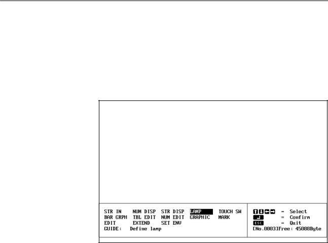
1-10 Editing Screens
If you select a screen number from the Screen Selection Display, the Initial Edit Display will be displayed. If the NT20M has been selected with Tool Settings, then the NT20M screen image display area will be shown in the rectangular box at the top of the display. If the NT600M has been selected, then the entire display becomes a display area and this box will not appear.
Initial Edit Display
Screen Edit Operations |
The following operations can be performed on the Edit Display. |
|
|
|
|
|
|
Item |
|
Function |
Page |
|
|
|
|
Input string (STR |
Inputs character strings to be displayed on the screen and sets their display positions and |
22 |
|
IN) |
the manner in which they are to be displayed. Character strings input in this way are treated |
|
|
|
as fixed displays, and their displays cannot be changed while the Programmable Terminal is |
|
|
|
operating. |
|
|
|
|
|
|
Numeral display |
Sets numeric displays for the screen by designating the numeral table entry to be referenced |
28 |
|
(NUM DISP) |
at the time of display, the display position, and the method of display. |
|
|
|
|
|
|
String display (STR |
Sets character string displays for the screen by designating the string table entry to be |
34 |
|
DISP) |
referenced at the time of display, the display position, and the method of display. |
|
|
|
|
|
|
Lamps (LAMP) |
Sets lamps for the screen by designating the size/shape of lamp areas, numbers, and labels. |
40 |
|
|
|
|
|
Touch switches |
Sets touch switches for the screen by designating the size of touch switch areas, numbers, |
46 |
|
(TOUCH SW) |
and labels. |
|
|
|
|
|
|
Bar graphs (BAR |
Sets bar graphs for the screen by designating the numeral table entry to use, the display |
51 |
|
GRPH) |
positions/directions, and the method of display. The display of percentage calculations is |
|
|
|
also set. |
|
|
|
|
|
|
Table editing (TBL |
Edits numeral table and character string table contents, and is the same as the table editing |
59 |
|
EDIT) |
operation entered from the Screen Selection Display. |
|
|
|
|
|
|
Numeral editing |
Creates screens for numeric input via function keys, touch switches, or Expansion I/O Units |
62 |
|
(NUM EDIT) |
(32/16 Terminals or Function Key Units (12 keys)) and designates the numeral table to which |
|
|
|
the input will be written. |
|
|
|
|
|
|
Graphic input |
Polylines (a broken line made up of one or more line segments) and circles can be created |
71 |
|
(GRAPHIC) |
on screen. |
|
|
|
|
|
|
Marks (MARK) |
Creates and modifies marks. |
82 |
|
|
|
|
|
Edit (EDIT) |
Copies, moves, or deletes text or graphics on the screen. |
87 |
|
11

Inputting Character Strings and Numbers |
Section 1-11 |
|||
|
|
|
|
|
Item |
Function |
|
Page |
|
|
|
|
|
|
Extended |
Enables usage of stand-alone operation. In stand-alone operation, screens can be changed |
85 |
|
|
Functions |
from PT touch switches/function keys or from Expansion I/O Units. |
|
|
|
(EXTEND) |
Sets data area allocations, comments, and other information for use with direct connection |
19 |
|
|
|
|
|||
|
operation. This function key appears only if direct connection has been turned ON in the Tool |
|
|
|
|
Settings. |
|
|
|
|
|
|
|
|
Set Environment |
Accesses a modified version of the Tool Settings to enable changing certain Support Tool |
16 |
|
|
(SET ENV) |
operating parameters during operation. |
|
|
|
Changing Menu Position and Grid Display
While creating data for the NT600M, there may be times when the screen data and the menu box overlap, making it difficult to see what you are doing. In such cases, you cam move or delete the menu box. The grid display can also be turned ON and OFF for either the NT600M or NT20M by pressing the Delete Key as long as grid display has been enabled in the tool settings (See page 15). The display position of the menu box and will change each time you press the Home Key as shown in the following tables.
NT600M with Grid Enabled
Delete Key |
Initial |
1 |
2 |
3 |
4 |
5 |
6 |
inputs |
|
|
|
|
|
|
|
|
|
|
|
|
|
|
|
Menu |
Bottom |
Top |
None |
Bottom |
Top |
None |
Bottom |
|
|
|
|
|
|
|
|
Grid |
ON |
ON |
OFF |
OFF |
OFF |
ON |
ON |
NT600M with Grid Disabled |
Delete Key inputs |
Initial |
1 |
2 |
3 |
|
|
|
|
|
|
Menu |
Bottom |
Top |
None |
Bottom |
|
Grid |
OFF |
OFF |
OFF |
OFF |
|
|
|
|
|
|
|
|
|
|
|
|
|
NT20M |
|
|
|
|
|
|
|
|
|
|
|
|
Delete Key inputs |
Initial |
1 |
2 |
|
|
|
|
|
|
|
|
Menu |
Bottom |
Bottom |
Bottom |
|
|
|
|
|
|
|
|
Grid |
ON |
OFF |
ON |
|
Note 1. The display position of the menu cannot be changed for the NT20M.
2.Screen data cannot be created and you cannot switch to the Screen Selection Display unless the menu is displayed.
1-11 Inputting Character Strings and Numbers
Inputting Character Strings You can use the Left, Right, Backspace, Delete, Insert, and Escape Keys when inputting character strings. Their functions are described below.
|
|
Moves the cursor to the left. |
|
|
Moves the cursor to the right. |
|
|
Deletes one character to the left of the cursor. |
BS |
||
|
|
Deletes one character at the cursor position. |
DEL |
|
|
|
|
Switches between insert mode and overwrite mode. |
INS |
|
|
|
|
Cancels character input string and returns to previous operation. |
ESC |
|
In insert mode, the cursor becomes a flashing rectangle and character strings are inserted at the cursor position. When text is inserted in this way, character strings to the right of the cursor position move to the right.
12

Basic Operation |
Section 1-12 |
|
|
|
|
In overwrite mode, the cursor becomes a reversed rectangle and character strings delete previously input characters at the cursor position.
Inputting Numbers |
Inputting numbers is basically the same as inputting character strings, except |
|
that you cannot change between insert mode and overwrite mode with the |
|
Insert Key. The overwrite mode is always used. |
|
The Home Key can be used to change to 0 any numbers previously input, |
|
and the Minus (±) Key can be used to change between positive and negative |
|
numbers. |
Control Key Combinations The Control Key can be used in combination with other keys to move the cursor, delete characters, and achieve other operations. These combinations are shown in the following table.
Keys |
Same as |
|
|
CTRL + S |
Left Cursor Key |
|
|
CTRL + D |
Right Cursor Key |
|
|
CTRL + E |
Up Cursor Key |
|
|
CTRL + X |
Down Cursor Key |
|
|
CTRL + R |
Page Up Key |
|
|
CTRL + C |
Page Down Key |
|
|
CTRL + H |
Backspace Key |
|
|
CTRL + G |
Delete Key |
|
|
CTRL + I |
Tab Key |
|
|
CTRL + M |
Enter Key |
|
|
CTRL + [ |
Escape Key |
1-12 Basic Operation
1-12-1 Cursors
Several different cursors will appear depending on Support Tool operation.
Special cursors are described in the following table.
Cursor |
Meaning |
|
|
|
The arrow cursor is used in combination with the cursor to specify |
|
menu items and icons. Refer to page 14 for details on the mouse. |
|
|
|
A cup will appear when the Support Tool is accessing data on the |
|
disk. When accessing has finished, the arrow cursor will return. |
|
|
|
A question mark will appear when the Support Tool is waiting for |
|
a Yes/No response from the user. Press the Enter Key or the left |
|
mouse button to answer Yes (confirm) or press the Escape Key |
|
or right mouse button to answer No (cancel). |
|
|
|
A hand and keyboard will appear at the end of processing to |
|
request user acknowledgement. Press any key or either mouse |
|
button to continue operation. |
13

Basic Operation |
Section 1-12 |
|
|
|
|
1-12-2 Screen Buttons
There are many buttons in the shape of keys that can appear during Support Tool operation. These buttons can be clicked with the mouse to achieve the same operation as the equivalent keyboard keys. Included are the Enter Key (carriage return arrow), Escape Key, cursor keys, PgUp Key, PgDn Key, Space Bar, Shift+Home (clear) Key (one button combining two keys), the Home (clear) Key, and function keys.
1-12-3 Mouse
|
A mouse can be connected to the Support Tool and used to input coordinates |
|
to specify display positions for text strings or numerals and to create poly- |
|
lines, circles, and other graphics. |
|
To use a mouse, connect a two-button mouse to the computer's mouse con- |
|
nector and prepare a level, smooth surface, such as a mouse pad, to operate |
|
it on. The mouse can then be used to move labels, the + cursor, and other |
|
objects on the screen (see below). |
|
Procedures in this manual are generally written for operation from the key- |
|
board. There are, however, often three means to execute an operation, i.e., |
|
from the keyboard, using on-screen buttons, and using the mouse and cursor |
|
directly. It is generally a matter of preference on which method is used; the |
|
results will be the same. |
Left Button |
The left mouse button can be used in place of the Enter Key to achieve the |
|
following. |
|
•To specify items on menus. Click the mouse once to move the cursor and |
|
then again to execute. |
|
•To click on-screen buttons to replace keyboard key inputs. See page 14 for |
|
details. |
|
•Double-clicking to end polyline input (instead of Shift + Enter). |
|
•Dragging to move objects on screen or draw lines. |
|
•To designate display positions for text or numerals |
|
•To designate display positions for touch switches, lamps, and bar graphs |
|
•To designate center, start, and end points for graphics |
Right Button |
The right mouse button can be clicked in place of pressing the Escape Key to |
|
move backward through processing steps or to cancel an operation. |
|
Caution Although either the mouse or the keyboard can be used for most operations, |
|
some operations have been restricted to only keyboard operation for safety. If |
|
the software does not respond when a mouse button is pressed, use the key- |
|
board instead. |
1-12-4 Positioning Operations
Grid display can be set via the Tool Settings, and grid display and snap-to- grid operation can be set via the Set Environment settings. The grid can be used either to visually align objects on the display or it can be combined with snap-to-grid operation to force objects to be positioned exactly on the grid. Refer to pages 15 and 16 for details.
14
Tool Settings |
Section 1-13 |
|
|
|
|
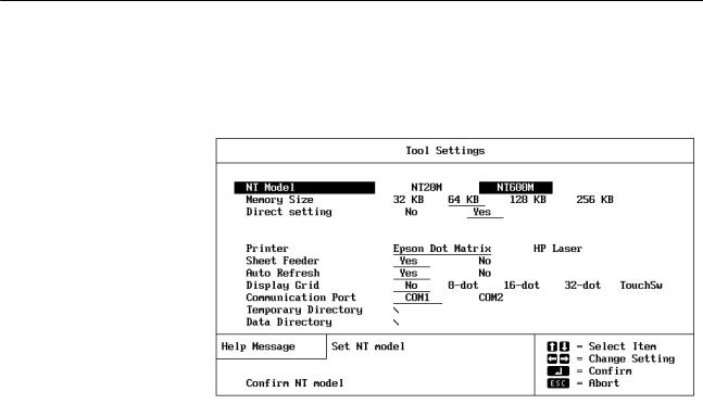
1-13 Tool Settings
If you start up the Support Tool and select Tool Settings from the Main Menu, the Tool Settings Display will appear.
Contents of Tool Settings
Name |
Content |
|
|
NT Model |
Sets the model of Programmable Terminal being used. |
|
|
Memory Size |
Sets the memory capacity of the Programmable Terminal. |
|
|
Direct Setting |
Turns ON and OFF the direct connection operation. Refer to |
|
page 17 for details. |
|
|
Printer |
Sets the printer model to be used. |
|
|
Sheet Feeder |
Sets a sheet feeder for the printer. |
|
|
Auto Refresh |
Sets whether or not the screen will be automatically |
|
refreshed when you make screen data additions, deletions, |
|
or modifications. |
|
|
Display Grid |
Controls the grid display. If ªTouchSWº is specified, each grid |
|
unit will be the size of a touch switch. |
|
|
Communication |
Specify the port on the computer to be used to communicate |
Port |
with the PT. If possible, do not specify the same port as the |
|
one used for the mouse. |
|
|
Temporary |
Sets the file name for the work file that is temporarily used by |
Directory |
the Support Tool. |
|
|
Data Directory |
Sets directory names for saving screen data which is |
|
created. |
|
Press the Enter Key when you want to save the contents of the Tool Settings. |
|
Then either press the Enter Key again to return to the Main Menu, or press |
|
the Escape Key to return to the Tool Settings Display to correct settings. |
|
If you press the Space Key, the tool settings will be changed without being |
|
saved to a file, and you will be returned to the Main Menu. |
|
Press the Escape Key to cancel changing tool settings. |
Auto Refresh |
When screen data is added, deleted, or modified with the Support Tool, the |
|
screen display may be temporarily disordered. If Auto Refresh is set to ªYes,º |
|
then the screen display will be automatically rewritten when you return to the |
|
Initial Edit Screen. When creating large amounts of screen data, however, |
|
some time may be required for screen refreshing. Auto Refresh can be set to |
15
Environment Settings |
Section 1-14 |
|
|
ªNoº to save time. You can manually rewrite the screen by pressing the Tab |
|
|
Key during operation. |
|
Temporary Directory |
The Support Tool will create a temporary work file when creating screens or |
|
|
transferring data to or from ROM. Most write operations are performed on |
|
|
this temporary file. To increase overall operating speed, this file should be |
|
|
created on your hard disk or in RAM. |
|
Tool Settings File |
File settings are saved in the root directory for the Support Tool, i.e., the di- |
|
|
rectory from which the Support Tool is started. The file name is |
|
|
NTMSET.ENV. If this file exists in the root directory when the Support Tool is |
|
|
started, the setting in the file will be read and the Support Tool will operate |
|
|
according to them. Tool settings files can be used to eliminate the need to |
|
|
reset tool setting each time the Support Tool is started. |
|
Display Grid |
A grid can be displayed to aid in positioning objects when creating screens. |
|
|
The Tool Settings can be used to disable the grid or to set its size to 8, 16, or |
|
|
32 dots. The grid size can also be set to the same size as a touch switch by |
|
|
specifying ªTouchSW.º The grid, once enabled, can be turned ON or OFF as |
|
|
desired during operation. Refer to page 12 for details. |
|
1-14 Environment Settings
A modified version of the Tool Settings can be accessed from the Initial Edit
Display. The following display will appear when SET ENV is specified.
Set the PT operating environment as described in the following table.
16

Direct Connection |
|
Section 1-15 |
||
|
|
|
|
|
|
Item |
Settings |
Setting |
|
|
|
|
|
|
|
Display grid |
No |
Display grid is not displayed. |
|
|
|
|
|
|
|
|
8-dot |
Display grid is displayed at the specified width. Screen |
|
|
|
16-dot |
objects can be snapped to the grid if one of these |
|
|
|
32-dot |
settings is made and the snap ON function is turned |
|
|
|
|
ON (see below). |
|
|
|
|
|
|
|
|
Touch |
Display grid is displayed at the minimum width for |
|
|
|
switch |
touch switches. This setting is useful to draw lamps to |
|
|
|
|
the same size as touch switches. It functions the same |
|
|
|
|
way as the other grids. |
|
|
|
|
|
|
|
Snap ON |
Off |
Allows graphics to be drawn and screen objects to be |
|
|
function |
|
positioned without interference from the grid, i.e., the |
|
|
|
|
grid, if displayed, is used only as a visual guide. |
|
|
|
|
|
|
|
|
On |
Allows graphics to be drawn and screen object to be |
|
|
|
|
positioned only to the intersection points of the grid. |
|
|
|
|
|
|
|
Lamp/touch |
No |
Lamp/touch switch numbers or bit addresses are not |
|
|
switch number |
|
displayed. |
|
|
display |
|
|
|
|
1/16 |
Indicates lamp/touch switch specifications and the |
||
|
|
|||
|
|
1/4 |
allocated lamp/touch switch number or the allocated |
|
|
|
|
PC bit on the display at the specified character size. |
|
|
|
|
For example, ªLH001015º would be displayed for a |
|
|
|
|
lamp display allocated to HR 1015 using direction |
|
|
|
|
connection, ªTA001012ºwould be displayed for a touch |
|
|
|
|
switch display allocated to AR 1012 using direction |
|
|
|
|
connection, L000 would be displayed for lamp #0 when |
|
|
|
|
not using direction connection, and T010 would be |
|
|
|
|
displayed for touch switch #10. |
|
|
|
|
|
|
|
Memory table |
No |
Memory table entry numbers are not displayed. |
|
|
entry number |
|
|
|
|
1/16 |
Indicates the allocated memory table number on the |
||
|
display |
|||
|
1/4 |
display at the specified character size for numeral |
||
|
|
|||
|
|
|
displays, character string displays, bar graphs, and |
|
|
|
|
numeral editing areas. ªNº is also displayed for |
|
|
|
|
numeral table entry numbers and ªSº is displayed for |
|
|
|
|
character string table entry numbers. |
|
1-15 Direct Connection
The PT can be set for direct connection to an OMRON PC to allow numeral displays, character displays, numeral editing, lamps, touch switches, and bar graphs to be directly connected to specific bits and words in PC memory. Bits can also be set that will change the displayed screen. This is possible only when the NT600M-DT121/DT211 or NT20M-DT121-V1/DT131 PTs and only when a NT600M-LK201 SYSMAC WAY Host Interface Unit is used. Also, either an NT600M-SMR31 or NT20M-SMR31 System ROM must be used in the PT.
The direct connection setting in the Tool Settings greatly affects the operation of the screen functions that read or write PC memory. Although using direction connection will greatly reduce programming burden for the PC, careful preparation is required to coordinate PC memory and programming with the PT settings for direct connection. The general procedure for this is as follows:
1, 2, 3... 1. Design the required PT screens.
2.Allocate PC memory to the function elements of the screens, i.e., those elements that will directly read or write PC memory. Be sure to list specific PC memory addresses, including areas, and to consider numeral table and character string table capacities.
3.Turn ON direct connection operation in the Tool Settings.
17

Direct Connection |
|
Section 1-15 |
|
|
4. |
Create the required screens, making all settings required for direct con- |
|
|
|
nection. |
|
|
5. |
Save the screens. |
|
|
6. |
Transfer the screens to the PT or write them to ROM. |
|
Conversion |
Screen files that were created with direct connection turned OFF can be |
||
|
loaded with direct connection turned ON to convert the screens for use with |
||
|
direct connection. Once files are created for or converted to direct connec- |
||
|
tion, they cannot be loaded with direct connection turned OFF in the Tool |
||
|
Settings and cannot be converted back for use without direct connection. |
||
Indication on Displays |
Displays on the File Selection Display and the Screen Selection display will |
||
|
indicate whether or not direct connection has been set. If direct connection |
||
has been set, ª-Oº (for OMRON) will be added after the PT model name following the ªFile Listº title on the File Selection Display. The help message area on the Screen Selection Display will also indicate whether or not direct connection has been used together with the file size.
1-15-1 Specifying PC Addresses for Direct Connection
The function keys are allocated as shown in the following table when specifying bit and word addresses in PC memory. The values in parentheses indicate the maximum word address possible for the largest PC memory. Actual memory sizes vary, however, with the model of PC. Refer to your PC's operation manual for specific limits.
Key |
Area |
|
|
F1 |
AR (511) |
|
|
F2 |
HR (99) |
|
|
F3 |
LR (63) |
|
|
F4 |
DM (9999) |
|
|
F5 |
CNT (1023) |
|
|
F6 |
TIM (1023) |
|
|
F7 |
CIO, IR, SR (2555) (displayed as |
|
I/S) |
|
|
Home |
None |
The areas that can be designated for direct connection are as shown in the following table.
Item |
Memory unit |
Designation |
|
|
|
Lamps |
Bit |
IR, SR (CIO), AR, or LR bit addresses. |
|
|
DM word address can also be designated with |
|
|
bit specifications. |
Touch switches |
|
|
|
Timers and counters cannot be designated. |
|
|
|
|
|
|
(See note.) |
|
|
|
Numeral display |
Word |
IR, SR (CIO), AR, LR, or DM word addresses. |
|
|
Timer and counter numbers can also be |
Bar graphs |
|
|
|
|
specified to designate PVs. |
Numeral editing |
|
|
|
|
|
|
|
|
Character string |
|
IR, SR (CIO), AR, LR, or DM word addresses. |
display |
|
Timer and counter numbers cannot be |
|
|
|
|
|
specified. |
Note If touch switches are set to write to bits in the DM area (notify bits), the touch switch will control the status of the specified bit and all other bits in the specified word will be turned OFF (0).
18
Direct Connection |
Section 1-15 |
|
|
|
|
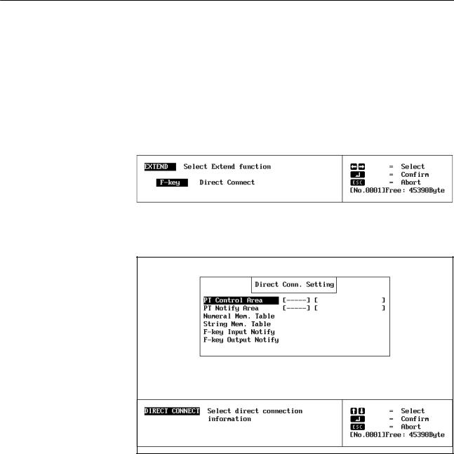
1-15-2 Direct Connection Information
Settings for the direct connection information are made from the extended functions display. Direct connection information settings will not appear on the extended function display unless direct connection is turned ON in the Tool Settings.
Use the following procedure to set the direct connection information settings.
1, 2, 3... 1. Specify EXTEND from the Initial Edit Display. The following display will appear at the bottom of the screen
2.Specify direct connection. (F-key is not supported by PTs with touch panels and cannot be specified.) The following display will appear.
3.Set the direct connection information as described in the following table.
Item |
Setting |
|
|
PT control area |
Set the address of the first word in the PC to be used to |
|
control PT status. This setting must be made. A user |
|
comment may also be input if desired. |
|
|
PT notify area |
Set the address of the first word in the PC to be used to |
|
store PT status. This setting must be made. A user |
|
comment may also be input if desired. |
|
|
Numeral mem. table |
The contents of the numeral table used in the file can be |
|
seen in list form. Data can be input or changed. |
|
|
String mem. table |
The contents of the character string table used in the file |
|
can be seen in list form. Data can be input or changed. |
|
|
F-key input/output notify |
Function keys cannot be set for PTs with touch panels. |
|
These settings are not required and will be ignored if |
|
input. |
4.When the settings have been completed, press the Escape Key once to return to the beginning of the operation and twice to end.
19
SECTION 2
Creating Screens
This section describes the procedures used to create and check screens and to input screen attributes. The procedures for creating special display characters, called marks, and for controlling screens during stand-alone operation are also provided here.
2-1 |
Inputting Character Strings . . . . . . . . . . . . . . . . . . . . . . . . . . . . . . . . . . . . . . . . . . . . . . . . . |
22 |
|
|
2-1-1 |
New Character Strings . . . . . . . . . . . . . . . . . . . . . . . . . . . . . . . . . . . . . . . . . . . . . . |
22 |
|
2-1-2 |
Deleting Character Strings . . . . . . . . . . . . . . . . . . . . . . . . . . . . . . . . . . . . . . . . . . . |
25 |
|
2-1-3 |
Modifying Character Strings . . . . . . . . . . . . . . . . . . . . . . . . . . . . . . . . . . . . . . . . . |
26 |
2-2 |
Numeral Displays . . . . . . . . . . . . . . . . . . . . . . . . . . . . . . . . . . . . . . . . . . . . . . . . . . . . . . . . . |
28 |
|
|
2-2-1 |
Normal Numeral Displays . . . . . . . . . . . . . . . . . . . . . . . . . . . . . . . . . . . . . . . . . . . |
28 |
|
2-2-2 Direct Connection Numeral Displays . . . . . . . . . . . . . . . . . . . . . . . . . . . . . . . . . . |
31 |
|
2-3 |
Character String Displays . . . . . . . . . . . . . . . . . . . . . . . . . . . . . . . . . . . . . . . . . . . . . . . . . . . |
34 |
|
|
2-3-1 Normal Character String Displays . . . . . . . . . . . . . . . . . . . . . . . . . . . . . . . . . . . . . |
35 |
|
|
2-3-2 Direct Connection Character String Displays . . . . . . . . . . . . . . . . . . . . . . . . . . . . |
37 |
|
2-4 |
Lamps . |
. . . . . . . . . . . . . . . . . . . . . . . . . . . . . . . . . . . . . . . . . . . . . . . . . . . . . . . . . . . . . . . . . |
40 |
|
2-4-1 |
Normal Lamps . . . . . . . . . . . . . . . . . . . . . . . . . . . . . . . . . . . . . . . . . . . . . . . . . . . . |
40 |
|
2-4-2 |
Direct Connection Lamps . . . . . . . . . . . . . . . . . . . . . . . . . . . . . . . . . . . . . . . . . . . |
43 |
2-5 |
Touch Switches . . . . . . . . . . . . . . . . . . . . . . . . . . . . . . . . . . . . . . . . . . . . . . . . . . . . . . . . . . |
46 |
|
|
2-5-1 |
Normal Touch Switches . . . . . . . . . . . . . . . . . . . . . . . . . . . . . . . . . . . . . . . . . . . . . |
46 |
|
2-5-2 Direct Connection Touch Switches . . . . . . . . . . . . . . . . . . . . . . . . . . . . . . . . . . . . |
48 |
|
2-6 |
Bar Graphs . . . . . . . . . . . . . . . . . . . . . . . . . . . . . . . . . . . . . . . . . . . . . . . . . . . . . . . . . . . . . . |
51 |
|
|
2-6-1 Creating Normal Bar Graphs . . . . . . . . . . . . . . . . . . . . . . . . . . . . . . . . . . . . . . . . . |
52 |
|
|
2-6-2 Direct Connection Bar Graphs . . . . . . . . . . . . . . . . . . . . . . . . . . . . . . . . . . . . . . . . |
55 |
|
2-7 |
Editing Memory Tables . . . . . . . . . . . . . . . . . . . . . . . . . . . . . . . . . . . . . . . . . . . . . . . . . . . . |
59 |
|
|
2-7-1 |
Normal Operation . . . . . . . . . . . . . . . . . . . . . . . . . . . . . . . . . . . . . . . . . . . . . . . . . |
59 |
|
2-7-2 |
Direction Connection Operation . . . . . . . . . . . . . . . . . . . . . . . . . . . . . . . . . . . . . . |
61 |
2-8 |
Numeral Editing . . . . . . . . . . . . . . . . . . . . . . . . . . . . . . . . . . . . . . . . . . . . . . . . . . . . . . . . . . |
62 |
|
|
2-8-1 |
Normal Numeral Editing . . . . . . . . . . . . . . . . . . . . . . . . . . . . . . . . . . . . . . . . . . . . |
63 |
|
2-8-2 Direct Connection Numeral Editing . . . . . . . . . . . . . . . . . . . . . . . . . . . . . . . . . . . |
68 |
|
|
2-8-3 Precautions for Numeral Editing . . . . . . . . . . . . . . . . . . . . . . . . . . . . . . . . . . . . . . |
70 |
|
2-9 |
Polylines . . . . . . . . . . . . . . . . . . . . . . . . . . . . . . . . . . . . . . . . . . . . . . . . . . . . . . . . . . . . . . . . |
71 |
|
|
2-9-1 |
Creating New Polylines . . . . . . . . . . . . . . . . . . . . . . . . . . . . . . . . . . . . . . . . . . . . . |
71 |
|
2-9-2 |
Deleting Polylines . . . . . . . . . . . . . . . . . . . . . . . . . . . . . . . . . . . . . . . . . . . . . . . . . |
72 |
|
2-9-3 |
Modifying Polylines . . . . . . . . . . . . . . . . . . . . . . . . . . . . . . . . . . . . . . . . . . . . . . . |
72 |
2-10 |
Circles . |
. . . . . . . . . . . . . . . . . . . . . . . . . . . . . . . . . . . . . . . . . . . . . . . . . . . . . . . . . . . . . . . . . |
73 |
|
2-10-1 |
Creating New Circles . . . . . . . . . . . . . . . . . . . . . . . . . . . . . . . . . . . . . . . . . . . . . . . |
73 |
|
2-10-2 |
Deleting Circles . . . . . . . . . . . . . . . . . . . . . . . . . . . . . . . . . . . . . . . . . . . . . . . . . . . |
74 |
|
2-10-3 |
Modifying Circles . . . . . . . . . . . . . . . . . . . . . . . . . . . . . . . . . . . . . . . . . . . . . . . . . |
74 |
2-11 |
Continuous and Overlapping Screens . . . . . . . . . . . . . . . . . . . . . . . . . . . . . . . . . . . . . . . . . |
75 |
|
2-12 |
Screen Attributes . . . . . . . . . . . . . . . . . . . . . . . . . . . . . . . . . . . . . . . . . . . . . . . . . . . . . . . . . |
78 |
|
2-13 |
Screen Check . . . . . . . . . . . . . . . . . . . . . . . . . . . . . . . . . . . . . . . . . . . . . . . . . . . . . . . . . . . . |
80 |
|
2-14 |
Marks . |
. . . . . . . . . . . . . . . . . . . . . . . . . . . . . . . . . . . . . . . . . . . . . . . . . . . . . . . . . . . . . . . . . |
82 |
2-15 |
Stand-alone Operation . . . . . . . . . . . . . . . . . . . . . . . . . . . . . . . . . . . . . . . . . . . . . . . . . . . . . |
85 |
|
2-16 |
Edit . . . . |
. . . . . . . . . . . . . . . . . . . . . . . . . . . . . . . . . . . . . . . . . . . . . . . . . . . . . . . . . . . . . . . . |
87 |
21
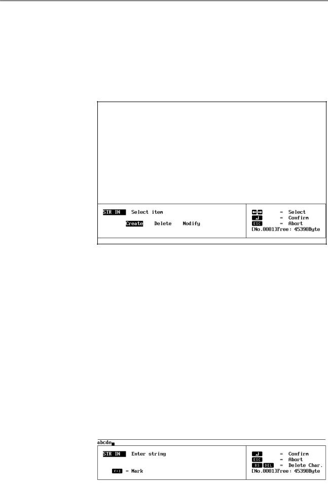
Inputting Character Strings |
Section 2-1 |
|
|
|
|
2-1 Inputting Character Strings
With the Character Input Display, you set characters to be displayed on the PT. You set character sizes, character scaling factors, manner of display, and display positions.
If you select STR IN from the Initial Edit Display, the Initial Character Input
Display will appear.
Initial Character Input Display
The following pages explain how to use this display, taking the creation of
NT20M screen data as an example.
2-1-1 |
New Character Strings |
||
Inputting Strings |
This example shows how to input the roman letters ªabcde.º |
||
|
|
You can display up to 32 characters per line on a NT20M screen, and up to |
|
|
|
80 per line on a NT600M screen. |
|
|
1, 2, 3... |
1. |
Specify CREATE. |
|
|
2. |
Input the characters, e.g., ªabcde.º The following display will appear. |
|
|
|
|
|
|
|
|
22
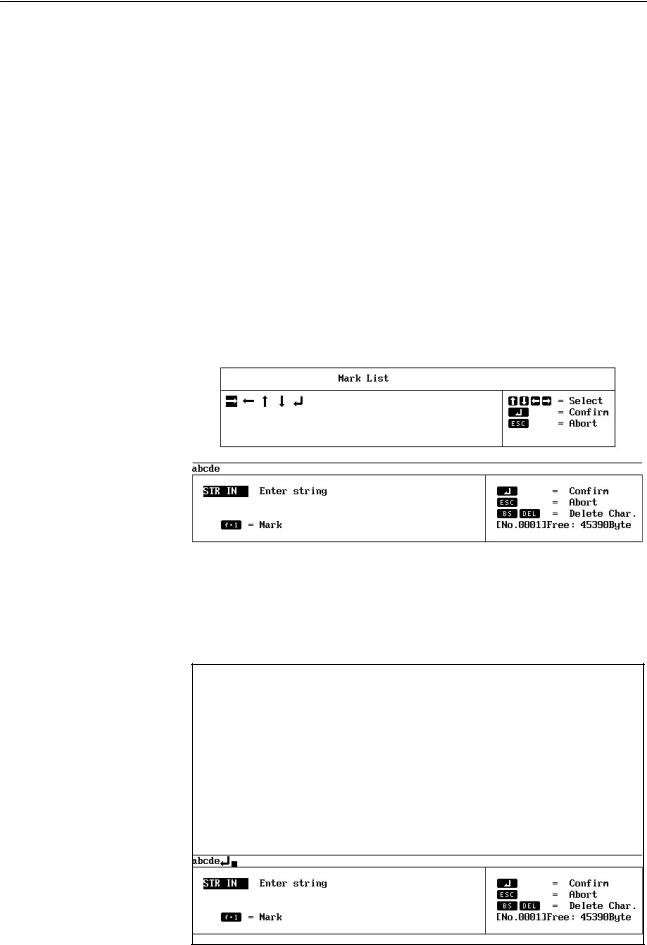
Inputting Character Strings |
|
Section 2-1 |
|
|
|
|
|
|
3. |
If the input is correct, press the Enter Key to enter the characters and go |
|
|
|
to the String Attributes section on page 24. Special characters or Marks |
|
|
|
can also be input as display characters as described below. |
|
Special Characters |
Characters not on the keyboard can be input via character codes. A list of |
||
|
character codes is provided at the end of the manual. To input a character |
||
|
code, press the ALT Key followed by the decimal code. |
||
Marks |
You can input marks while inputting characters. |
||
1, 2, 3... |
1. |
Press F1 (Mark) while inputting a string. The Mark List will appear. |
|
|
|
|
|
|
|
|
|
2.Use the direction keys to select the mark you want to input, and then press the Enter Key to enter them, or press the Escape Key to cancel mark input and return to character input.
23
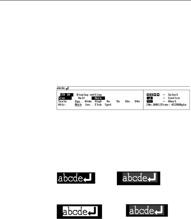
Inputting Character Strings |
Section 2-1 |
||
String Attributes |
Here you set the size, scale, and attributes for character strings that have |
|
|
|
been input. |
||
|
|
|
|
|
|
|
|
1, 2, 3... 1. Set the size to be used for each 1-byte character.
2.Set the scale factor for the characters. NT600M strings can be set to 64X in addition to the ones shown in the above display.
3.Set display attributes. ªSpotº is for flashing characters in reverse video. Display attributes will be displayed on the computer screen as shown below. (Although the contrast of most displays in this manual is reversed, the contrast of these examples is the same of that on the screen.
Normal |
Flashing |
Inverse |
Spot (Inverse Blinking) |
4.Press the Enter Key after checking the settings.
A display for designating string position will appear next.
Designating Display |
Designate the display position for the string. |
Position |
1. A rectangular guide box showing the size of the input character string |
1, 2, 3... |
|
|
will be displayed. The guide box is displayed according to the number of |
|
characters input to that point, and the scale which has been set. Set the |
|
display position on the screen with the direction keys. By operating the |
|
direction keys while pressing the Shift Key, you can move the guide box |
|
16 dots at a time. The X and Y coordinates of the display position (the X |
|
and Y coordinates of the lower left-hand corner of the guide box) are |
24
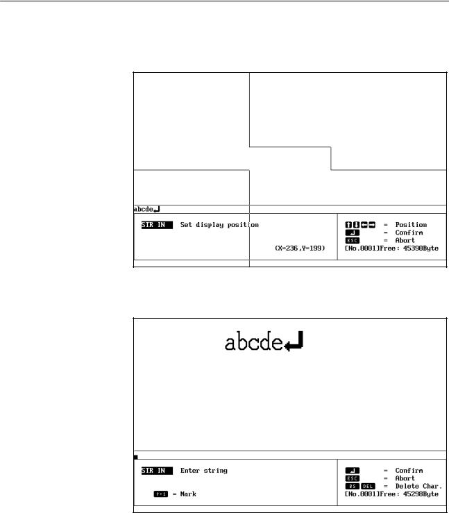
Inputting Character Strings |
Section 2-1 |
|
|
|
|
displayed. You cannot set a display position that allows the guide box to extend off the screen.
2.When you have set the display position, press the Enter Key.
3.You will be returned to the Initial Text Input Display, and the contents set up to this point are displayed. At this time, a message again appears in the command box instructing you to enter text. If you are inputting text to different places on the same screen, repeat the operations described above. When you have finished inputting text, press the Escape Key. You will be returned to the Initial Edit Display.
2-1-2 Deleting Character Strings
You can delete strings that have already been set by using the procedure given below. When you delete a string, a portion of the display may be left empty. If this happens, press the TAB Key to rewrite the display.
25

Inputting Character Strings |
Section 2-1 |
|
|
|
|
1, 2, 3... 1. Specify DELETE. The cross-shaped cursor will be displayed.
2.Line up the center of the cross-shaped cursor with the string you want to delete, and press the Enter Key. The string which you have selected will be outlined by a guide box. A message will appear in a comment box to verify whether you actually want to delete that string. If a number of characters have been input at one time, then it makes no difference which character you place the cross-shaped cursor on.
3.To delete the string, press the Enter Key, or to cancel, press any key other than the Enter Key.
The basic delete operation for other data on the Edit Display, e.g., numeral displays, is the same.
Note If the screen is not properly displayed after deleting, press the Tab Key to rescan the display.
2-1-3 Modifying Character Strings
You can modify strings that have already been set.
26
Loading...