


 Loading...
Cat. No. Z264-E1-06A
Smart Sensor ZFX-C
Vision Sensor
with built-in LCD monitor
USERS MANUAL
Introduction
Thank you for purchasing the ZFX-C.
This manual provides information regarding functions, performance and operating methods that are required for using the ZFX-C.
When using the ZFX-C, be sure to observe the following:
•The ZFX-C must be operated by personnel knowledgeable in electrical engineering.
•To ensure correct use, please read this manual thoroughly to deepen your understanding of the product.
•Please keep this manual in a safe place so that it can be referred to whenever necessary.
Manuals Provided with this Product
Smart Sensor
Vision Sensor with built-in LCD monitor
ZFX-C
User's Manual
Cat. No. XXXX-XX-XX
Smart Sensor
Vision Sensor with built-in LCD monitor
ZFX-C
Serial Communication
Command Reference
User's Manual (this document)
This manual describes basic operations, such as installation and connections, and information on settings and specifications to ensure safe and correct use of this product.
Serial Communication Command
Reference
This manual provides reference information for when this product performs communications with an external device, such as a PC or a programmable controller, via the serial interface.
Cat. No. XXXX-XX-XX
User's Manual
Smart Sensor
Vision Sensor with built-in LCD monitor ZFX-C
APPLICATION CONSIDERATIONS |
1 |
(Please Read) |
|
|
|
|
|
BEFORE USE |
1 |
|
|
|
|
BASIC OPERATIONS |
2 |
|
|
|
|
SETTING THE MEASUREMENT |
3 |
CONDITIONS |
|
|
|
FUNCTIONS USED DURING OPERA- |
4 |
TION |
|
|
|
ADDITIONAL FUNCTIONS |
5 |
|
|
|
|
PARALLEL INTERFACE |
6 |
|
|
|
|
APPENDICES |
7 |
|
|

READ AND UNDERSTAND THIS DOCUMENT
Please read and understand this document before using the products. Please consult your OMRON representative if you have any questions or comments.
WARRANTY
OMRON’s exclusive warranty is that the products are free from defects in materials and workmanship for a period of one year (or other period if specified) from date of sale by OMRON.
OMRON MAKES NO WARRANTY OR REPRESENTATION, EXPRESS OR IMPLIED, REGARDING NONINFRINGEMENT, MERCHANTABILITY, OR FITNESS FOR PARTICULAR PURPOSE OF THE PRODUCTS. ANY BUYER OR USER ACKNOWLEDGES THAT THE BUYER OR USER ALONE HAS DETERMINED THAT THE PRODUCTS WILL SUITABLY MEET THE REQUIREMENTS OF THEIR INTENDED USE. OMRON DISCLAIMS ALL OTHER WARRANTIES, EXPRESS OR IMPLIED.
LIMITATIONS OF LIABILITY
OMRON SHALL NOT BE RESPONSIBLE FOR SPECIAL, INDIRECT, OR CONSEQUENTIAL DAMAGES, LOSS OF PROFITS OR COMMERCIAL LOSS IN ANY WAY CONNECTED WITH THE PRODUCTS, WHETHER SUCH CLAIM IS BASED ON CONTRACT, WARRANTY, NEGLIGENCE, OR STRICT LIABILITY.
In no event shall responsibility of OMRON for any act exceed the individual price of the product on which liability is asserted.
IN NO EVENT SHALL OMRON BE RESPONSIBLE FOR WARRANTY, REPAIR, OR OTHER CLAIMS REGARDING THE PRODUCTS UNLESS OMRON’S ANALYSIS CONFIRMS THAT THE PRODUCTS WERE PROPERLY HANDLED, STORED, INSTALLED, AND MAINTAINED AND NOT SUBJECT TO CONTAMINATION, ABUSE, MISUSE, OR INAPPROPRIATE MODIFICATION OR REPAIR.
SUITABILITY FOR USE
THE PRODUCTS CONTAINED IN THIS DOCUMENT ARE NOT SAFETY RATED. THEY ARE NOT DESIGNED OR RATED FOR ENSURING SAFETY OF PERSONS, AND SHOULD NOT BE RELIED UPON AS A SAFETY COMPONENT OR PROTECTIVE DEVICE FOR SUCH PURPOSES.
Please refer to separate catalogs for OMRON’s safety rated products.
OMRON shall not be responsible for conformity with any standards, codes, or regulations that apply to the combination of products in the customer’s application or use of the product.
At the customer’s request, OMRON will provide applicable third party certification documents identifying ratings and limitations of use that apply to the products. This information by itself is not sufficient for a complete determination of the suitability of the products in combination with the end product, machine, system, or other application or use.
The following are some examples of applications for which particular attention must be given. This is not intended to be an exhaustive list of all possible uses of the products, nor is it intended to imply that the uses listed may be suitable for the products:
•Outdoor use, uses involving potential chemical contamination or electrical interference, or conditions or uses not described in this document.
2 |
ZFX-C User’s Manual |
|

•Nuclear energy control systems, combustion systems, railroad systems, aviation systems, medical equipment, amusement machines, vehicles, safety equipment, and installations subject to separate industry or government regulations.
•Systems, machines, and equipment that could present a risk to life or property.
Please know and observe all prohibitions of use applicable to the products.
NEVER USE THE PRODUCTS FOR AN APPLICATION INVOLVING SERIOUS RISK TO LIFE OR PROPERTY WITHOUT ENSURING THAT THE SYSTEM AS A WHOLE HAS BEEN DESIGNED TO ADDRESS THE RISKS, AND THAT THE OMRON PRODUCT IS PROPERLY RATED AND INSTALLED FOR THE INTENDED USE WITHIN THE OVERALL EQUIPMENT OR SYSTEM.
PERFORMANCE DATA
Performance data given in this document is provided as a guide for the user in determining suitability and does not constitute a warranty. It may represent the result of OMRON’s test conditions, and the users must correlate it to actual application requirements. Actual performance is subject to the OMRON Warranty and Limitations of Liability.
CHANGE IN SPECIFICATIONS
Product specifications and accessories may be changed at any time based on improvements and other reasons.
It is our practice to change model numbers when published ratings or features are changed, or when significant construction changes are made. However, some specifications of the product may be changed without any notice. When in doubt, special model numbers may be assigned to fix or establish key specifications for your application on your request. Please consult with your OMRON representative at any time to confirm actual specifications of purchased products.
DIMENSIONS AND WEIGHTS
Dimensions and weights are nominal and are not to be used for manufacturing purposes, even when tolerances are shown.
ERRORS AND OMISSIONS
The information in this document has been carefully checked and is believed to be accurate; however, no responsibility is assumed for clerical, typographical, or proofreading errors, or omissions.
PROGRAMMABLE PRODUCTS
OMRON shall not be responsible for the user’s programming of a programmable product, or any consequence thereof.
COPYRIGHT AND COPY PERMISSION
This document shall not be copied for sales or promotions without permission.
This document is protected by copyright and is intended solely for use in conjunction with the product. Please notify us before copying or reproducing this document in any manner, for any other purpose. If copying or transmitting this document to another, please copy or transmit it in its entirety.
|
3 |
|
ZFX-C User’s Manual |
||
|
Meanings of Signal Words
The following signal words are used in this manual.
Indicates a potentially hazardous situation which, if not avoided, will result in minor or moderate injury, or may result in serious injury or death. Additionally there may be significant property damage.
Meanings of Alert Symbols
The following alert symbols are used in this manual
Indicates general prohibitions for which there is no specific symbol.
Indicates the possibility of laser radiation.
Indicates the possibility of explosion under specific conditions.
This product is not designed or rated for ensuring safety of persons.
Do not use it for such purposes.
The camera with lighting emits visible light, which may adversely affect the eyes in rare instances. Do not look directly into the light emitted from the Camera. When the subject is a specular reflective object, protect your eyes from reflected light.
A lithium battery is built into the Controller and may occasionally combust, explode, or burn if not treated properly.
Dispose of the Controller as industrial waste, and never disassemble, apply pressure that would deform, heat to 100 °C or higher, or incinerate the Controller.
4 |
ZFX-C User’s Manual |
|

Precautions for Safe Use
The following points are important to ensure safety, so make sure that they are strictly observed.
1.Installation Environment
•Do not use the product in environments where it can be exposed to inflammable/explosive gas.
•To secure the safety of operation and maintenance, do not install the product close to high-voltage devices and power devices.
•Install the product in such a way that its ventilation holes are not blocked.
•Tighten mounting screws at the torque specified in this manual.
2.Power Supply and Wiring
•The voltage and AC power supply must be within the rated range (24 VDC ±10%).
•Reverse connection of the power supply is not allowed.
•Use the power supply within the rated load.
•High-voltage lines and power lines must be wired separately from this product. Wiring them together or placing them in the same duct may cause induction, resulting in malfunction or damage.
•Use the product within the power supply voltage specified in this manual.
•Use a DC power supply with safety measures against high-voltage spikes (safety extra low-voltage circuits on the secondary side).
•Tighten mounting screws at the torque specified in this manual.
3.Other
•Do not use this product in safety circuits associated with nuclear power and human life.
•Do not disassemble, repair, modify, deform by pressure, or incinerate this product.
•Dispose of this product as industrial waste.
•Connect the exclusive devices (Camera, Controller, Strobe Controller, Cable). The product might break down or malfunction if you use a part not included in the exclusive products.
•Should you notice any abnormalities, immediately stop use, turn OFF the power supply, and contact your OMRON representative.
4.Laws and Regulations, Standards
•This product complies with the following EC and EN directives: EC Directive No.2004/108/EC
EN Standards EN61326
|
5 |
|
ZFX-C User’s Manual |
||
|

Precautions for Correct Use
Observe the following precautions to prevent failure to operate, malfunctions, or undesirable effects on product performance.
1.Installation Site
Do not install this product in locations subjected to the following conditions:
•Ambient temperature outside the rating
•Rapid temperature fluctuations (causing condensation)
•Relative humidity outside the range of 35 to 85%
•Direct vibration or shock
•Reflection of intense light (such as other laser beams, electric arc-welding machines, or ultra-violet light)
•Direct sunlight or near heaters
•Strong magnetic or electric field
Also, do not install this product in locations subjected to the following conditions to ensure its protective performance as described in the specifications:
•Presence of corrosive or flammable gases
•Presence of dust, salt, or iron particles
•Water, oil, or chemical fumes or spray, or mist atmospheres
2.Power Supply and Wiring
•When using a commercially available switching regulator, make sure that the FG terminal is grounded.
•If surge currents are present in the power lines, connect surge absorbers that suit the operating environment.
•Before turning ON the power after the product is connected, make sure that the power supply voltage is correct, there are no incorrect connections (e.g. load short-circuit) and the load current is appropriate. Incorrect wiring may result in breakdown of the product.
•Before connecting/disconnecting cables, make sure that the product is turned OFF. The product may break down if it is connected/disconnected while the power is ON.
•For cables, use only the exclusive products specified in this manual.
 p.14, p.15
•Use only combinations of the Camera, Controller and Strobe Controller specified in this manual. Using other combinations may cause malfunction or damage.
•Do not turn the power OFF in the following instances. Doing so will damage data that is in the process of being saved.
-While data is being saved on the Controller
-While data is being saved on the SD card
•The LCD panel has been made using precision technology, and sometimes a few pixels are missing in the panel. This is due to the structure of the LCD panel, and is not a malfunction.
•Do not remove the base from the Camera.
3.Maintenance and Inspection
Do not use thinner, benzene, acetone or kerosene to clean the Camera and Controller. If large dust particles adhere to the Camera, use a blower brush (used to clean camera lenses) to blow them off. Do not use breath from your mouth to blow the dust off. To remove dust particles from the Camera, wipe gently with a soft cloth (for cleaning lenses) moistened with a small amount of alcohol. Do not use excessive force to wipe off dust particles. Scratches to the Camera might cause error.
4.Ventilation Film
•Do not peel of the ventilation film or prod it with a sharp-pointed object. This might impair its protective structure.
•Do not cover the ventilation film. Doing so might cause the Camera's front panel to cloud.
6 |
ZFX-C User’s Manual |
|

5.Optional Lighting Connector
When the optional lighting is not connected, be sure to attach the connector cap. Otherwise, its protective structure might be impaired.
6.Camera's Connector Cap
When using only one camera, attach the connector cap to cameras that are not in use.
7.Communication with a Host Device
Before communicating with a host device, make sure that the product has started up.
Also, clear the receive buffers on the device in use or perform other measures since undetermined signals might be output from the host interface when this product is started up.
|
7 |
|
ZFX-C User’s Manual |
||
|
Editor's Note
■ Meaning of Symbols
Menu items that are displayed on the Controller's LCD screen, and windows, dialog boxes and other GUI elements displayed on the PC are indicated enclosed by brackets "[ ]".
■ Visual Aids
|
|
|
Indicates points that are important to achieve the full product performance, |
|
Important |
||||
such as operational precautions. |
||||
|
|
|
||
|
|
|
Indicates application procedures. |
|
Note |
|
|||
|
|
|
Indicates pages where related information can be found. |
|
|
|
|
||
■ Difference between the ZFX-C20/C25, ZFX-C10H/C15H and ZFX-C10/C15
This manual is intended for the ZFX-C20/C25, ZFX-C10H/C15H and ZFX-C10/C15 Controllers.
Unless otherwise specified, explanations are given for the ZFX-C20/C25. The following table summarizes the main differences.
Item |
ZFX-C20/C25 |
ZFX-C10H/C15H |
ZFX-C10/C15 |
|
|
|
|
Number of connected cameras |
2 |
1 |
1 |
|
|
|
|
Available measurement items |
All available |
|
Only the following items are available: |
|
|
|
Pattern search |
|
|
|
Sensitive search |
|
|
|
Area |
|
|
|
Position |
|
|
|
Width |
|
|
|
Count |
|
|
|
Angle |
|
|
|
Bright |
|
|
|
Hue |
|
|
|
Defect |
|
|
|
|
Available position correction items |
All available |
|
Only the following items are available: |
|
|
|
Edge position |
|
|
|
Area |
|
|
|
1 model |
|
|
|
2 model |
|
|
|
Angle |
|
|
|
|
Number of measurement items that |
Max. 128 items/bank |
Max. 32 items/bank |
|
can be measured simultaneously |
|
|
|
|
|
|
|
Logging monitor function |
Available |
|
Not available |
|
|
|
|
8 |
ZFX-C User’s Manual |
|

CONTENTS
1.BEFORE USE
ZFX-C . . . . . . . . . . . . . . . . . . . . . . . . . . . . . . . . . . . . . . . . . . . . . . . . . . . . . . 14
System Configuration. . . . . . . . . . . . . . . . . . . . . . . . . . . . . . . . . . . . . . . . . . . . . . 14
Part Names and Functions . . . . . . . . . . . . . . . . . . . . . . . . . . . . . . . . . . . . . . . . . 16
Mounting and Connecting Devices . . . . . . . . . . . . . . . . . . . . . . . . . . . . . . 19
Installing Cameras . . . . . . . . . . . . . . . . . . . . . . . . . . . . . . . . . . . . . . . . . . . . . . . . 19
Installing the Controller . . . . . . . . . . . . . . . . . . . . . . . . . . . . . . . . . . . . . . . . . . . . 25
Connecting Devices . . . . . . . . . . . . . . . . . . . . . . . . . . . . . . . . . . . . . . . . . . . . . . . 28
Overview of Settings and Measurement . . . . . . . . . . . . . . . . . . . . . . . . . . 31
Operation Modes . . . . . . . . . . . . . . . . . . . . . . . . . . . . . . . . . . . . . . . . . . . . . . . . . 31 Outline of MENU mode . . . . . . . . . . . . . . . . . . . . . . . . . . . . . . . . . . . . . . . . . . . . 32 Measurement Items and Banks . . . . . . . . . . . . . . . . . . . . . . . . . . . . . . . . . . . . . . 33 Initializing Controller Settings. . . . . . . . . . . . . . . . . . . . . . . . . . . . . . . . . . . . . . . . 35 Saving Setup Data . . . . . . . . . . . . . . . . . . . . . . . . . . . . . . . . . . . . . . . . . . . . . . . . 36
2.BASIC OPERATIONS
Inspection Setup and Measurement . . . . . . . . . . . . . . . . . . . . . . . . . . . . . 38
Setting Measurement Conditions - MENU Mode . . . . . . . . . . . . . . . . . . . . . . . . . 38
Checking the Measurement Status - ADJ Mode . . . . . . . . . . . . . . . . . . . . . . . . . 42
Starting Measurement - RUN Mode. . . . . . . . . . . . . . . . . . . . . . . . . . . . . . . . . . . 42
Troubleshooting . . . . . . . . . . . . . . . . . . . . . . . . . . . . . . . . . . . . . . . . . . . . . 43
Clear Images Cannot be Obtained . . . . . . . . . . . . . . . . . . . . . . . . . . . . . . . . . . . 43 Measurement Target Cannot be Measured Accurately Due to Movement . . . . . 43 To Output Measurement Values to a PC or PLC. . . . . . . . . . . . . . . . . . . . . . . . . 44 To Output Position Information of Measurement Targets as Actual Coordinates 44
CONTENTS
|
9 |
|
ZFX-C User’s Manual |
||
|

3.SETTING THE MEASUREMENT CONDITIONS
Setting Measurement Items . . . . . . . . . . . . . . . . . . . . . . . . . . . . . . . . . . . . 46
Shape Inspection . . . . . . . . . . . . . . . . . . . . . . . . . . . . . . . . . . . . . . . . . . . . . . . . . 46
Pattern Search . . . . . . . . . . . . . . . . . . . . . . . . . . . . . . . . . . . . . . . . . . . . . . . . . 46 Graphic Search . . . . . . . . . . . . . . . . . . . . . . . . . . . . . . . . . . . . . . . . . . . . . . . . 51 Flexible Search. . . . . . . . . . . . . . . . . . . . . . . . . . . . . . . . . . . . . . . . . . . . . . . . . 56 Sensitive Search . . . . . . . . . . . . . . . . . . . . . . . . . . . . . . . . . . . . . . . . . . . . . . . 59 Size Inspection. . . . . . . . . . . . . . . . . . . . . . . . . . . . . . . . . . . . . . . . . . . . . . . . . . . 63
Area . . . . . . . . . . . . . . . . . . . . . . . . . . . . . . . . . . . . . . . . . . . . . . . . . . . . . . . . . 63 Labeling . . . . . . . . . . . . . . . . . . . . . . . . . . . . . . . . . . . . . . . . . . . . . . . . . . . . . . 67 Edge Inspection . . . . . . . . . . . . . . . . . . . . . . . . . . . . . . . . . . . . . . . . . . . . . . . . . . 71
Position. . . . . . . . . . . . . . . . . . . . . . . . . . . . . . . . . . . . . . . . . . . . . . . . . . . . . . . 71 Width . . . . . . . . . . . . . . . . . . . . . . . . . . . . . . . . . . . . . . . . . . . . . . . . . . . . . . . . 76 Count . . . . . . . . . . . . . . . . . . . . . . . . . . . . . . . . . . . . . . . . . . . . . . . . . . . . . . . . 80 Angle . . . . . . . . . . . . . . . . . . . . . . . . . . . . . . . . . . . . . . . . . . . . . . . . . . . . . . . . 83 Bright/Color Inspection. . . . . . . . . . . . . . . . . . . . . . . . . . . . . . . . . . . . . . . . . . . . . 87
Bright . . . . . . . . . . . . . . . . . . . . . . . . . . . . . . . . . . . . . . . . . . . . . . . . . . . . . . . . 87 HUE . . . . . . . . . . . . . . . . . . . . . . . . . . . . . . . . . . . . . . . . . . . . . . . . . . . . . . . . . 89 Inspection by Individual Application . . . . . . . . . . . . . . . . . . . . . . . . . . . . . . . . . . . 92
Grouping. . . . . . . . . . . . . . . . . . . . . . . . . . . . . . . . . . . . . . . . . . . . . . . . . . . . . . 92 Defect . . . . . . . . . . . . . . . . . . . . . . . . . . . . . . . . . . . . . . . . . . . . . . . . . . . . . . . . 95 Image Adjustment . . . . . . . . . . . . . . . . . . . . . . . . . . . . . . . . . . . . . . . . . . . . . . . . 99
Cameras/Lighting . . . . . . . . . . . . . . . . . . . . . . . . . . . . . . . . . . . . . . . . . . . 104
Shutter Speed . . . . . . . . . . . . . . . . . . . . . . . . . . . . . . . . . . . . . . . . . . . . . . . . . . 104
Gain Setting . . . . . . . . . . . . . . . . . . . . . . . . . . . . . . . . . . . . . . . . . . . . . . . . . . . . 104
Partial Function Settings . . . . . . . . . . . . . . . . . . . . . . . . . . . . . . . . . . . . . . . . . . 105
Image Rate . . . . . . . . . . . . . . . . . . . . . . . . . . . . . . . . . . . . . . . . . . . . . . . . . . . . 105
Light Control (Recipe Functions) . . . . . . . . . . . . . . . . . . . . . . . . . . . . . . . . . . . . 106
Calibration . . . . . . . . . . . . . . . . . . . . . . . . . . . . . . . . . . . . . . . . . . . . . . . . . . . . . 107
Registering Images . . . . . . . . . . . . . . . . . . . . . . . . . . . . . . . . . . . . . . . . . . 112
Position Correction . . . . . . . . . . . . . . . . . . . . . . . . . . . . . . . . . . . . . . . . . . 113
Additional Functions. . . . . . . . . . . . . . . . . . . . . . . . . . . . . . . . . . . . . . . . . 115
Calculation . . . . . . . . . . . . . . . . . . . . . . . . . . . . . . . . . . . . . . . . . . . . . . . . . . . . . 115
Setting Reflection of Individual Results . . . . . . . . . . . . . . . . . . . . . . . . . . . . . . . 119
Logging Monitor . . . . . . . . . . . . . . . . . . . . . . . . . . . . . . . . . . . . . . . . . . . . . . . . . 120
4.FUNCTIONS USED DURING OPERATION
Monitoring the Measurement Status - RUN Mode . . . . . . . . . . . . . . . . . 124
Displaying Measurement Information . . . . . . . . . . . . . . . . . . . . . . . . . . . . . . . . 124
Switching the Image Display Method. . . . . . . . . . . . . . . . . . . . . . . . . . . . . . . . . 126
Checking/Adjusting the Measurement - ADJ Mode . . . . . . . . . . . . . . . . 127
Checking Measurement Status . . . . . . . . . . . . . . . . . . . . . . . . . . . . . . . . . . . . . 127 Switching the Image Display Method. . . . . . . . . . . . . . . . . . . . . . . . . . . . . . . . . 129 Using a Saved Image to Perform Re-measurement . . . . . . . . . . . . . . . . . . . . . 129 Adjusting Measurement Conditions . . . . . . . . . . . . . . . . . . . . . . . . . . . . . . . . . . 130
10 |
ZFX-C User’s Manual |
|

5.ADDITIONAL FUNCTIONS
Bank Settings . . . . . . . . . . . . . . . . . . . . . . . . . . . . . . . . . . . . . . . . . . . . . . 134
Bank Data Operations . . . . . . . . . . . . . . . . . . . . . . . . . . . . . . . . . . . . . . . . . . . . 135
Bank Group Operations . . . . . . . . . . . . . . . . . . . . . . . . . . . . . . . . . . . . . . . . . . . 135
System Settings . . . . . . . . . . . . . . . . . . . . . . . . . . . . . . . . . . . . . . . . . . . . 136
Camera Specifications . . . . . . . . . . . . . . . . . . . . . . . . . . . . . . . . . . . . . . . . . . . . 136 Communication Setup . . . . . . . . . . . . . . . . . . . . . . . . . . . . . . . . . . . . . . . . . . . . 136 Output Settings . . . . . . . . . . . . . . . . . . . . . . . . . . . . . . . . . . . . . . . . . . . . . . . . . 140 Display Settings . . . . . . . . . . . . . . . . . . . . . . . . . . . . . . . . . . . . . . . . . . . . . . . . . 142 Operation Settings . . . . . . . . . . . . . . . . . . . . . . . . . . . . . . . . . . . . . . . . . . . . . . . 145 Measurement Control Conditions . . . . . . . . . . . . . . . . . . . . . . . . . . . . . . . . . . . 147 Operation Conditions during Startup . . . . . . . . . . . . . . . . . . . . . . . . . . . . . . . . . 148 Setting/Changing the Display Language . . . . . . . . . . . . . . . . . . . . . . . . . . . . . . 149 Setting/Changing the Date. . . . . . . . . . . . . . . . . . . . . . . . . . . . . . . . . . . . . . . . . 149 Clearing Saved Images . . . . . . . . . . . . . . . . . . . . . . . . . . . . . . . . . . . . . . . . . . . 149
Tools. . . . . . . . . . . . . . . . . . . . . . . . . . . . . . . . . . . . . . . . . . . . . . . . . . . . . . 150
Saving/Loading Data . . . . . . . . . . . . . . . . . . . . . . . . . . . . . . . . . . . . . . . . . . . . . 150 SD Card Operations. . . . . . . . . . . . . . . . . . . . . . . . . . . . . . . . . . . . . . . . . . . . . . 151 Checking Density Distribution (Profile) . . . . . . . . . . . . . . . . . . . . . . . . . . . . . . . 151 Checking the Communication Status with External Devices . . . . . . . . . . . . . . . 152 Displaying the Controller Information. . . . . . . . . . . . . . . . . . . . . . . . . . . . . . . . . 153
6.PARALLEL INTERFACE
Connection. . . . . . . . . . . . . . . . . . . . . . . . . . . . . . . . . . . . . . . . . . . . . . . . . 156
Parallel Connector Specifications . . . . . . . . . . . . . . . . . . . . . . . . . . . . . . . . . . . 156
Internal Specifications . . . . . . . . . . . . . . . . . . . . . . . . . . . . . . . . . . . . . . . 160
Signal I/O . . . . . . . . . . . . . . . . . . . . . . . . . . . . . . . . . . . . . . . . . . . . . . . . . . 162
Input Signal . . . . . . . . . . . . . . . . . . . . . . . . . . . . . . . . . . . . . . . . . . . . . . . . . . . . 162
Output Signal . . . . . . . . . . . . . . . . . . . . . . . . . . . . . . . . . . . . . . . . . . . . . . . . . . . 164
Timing Charts . . . . . . . . . . . . . . . . . . . . . . . . . . . . . . . . . . . . . . . . . . . . . . 167
Measurement (Handshaking OFF) . . . . . . . . . . . . . . . . . . . . . . . . . . . . . . . . . . 167 Measurement (Handshaking ON) . . . . . . . . . . . . . . . . . . . . . . . . . . . . . . . . . . . 170 Commands Other than for Measurement . . . . . . . . . . . . . . . . . . . . . . . . . . . . . 171 Signal Operation in terms of Measurement . . . . . . . . . . . . . . . . . . . . . . . . . . . . 172
CONTENTS
|
11 |
|
ZFX-C User’s Manual |
||
|

7.APPENDICES
Error Messages and Corrective Actions . . . . . . . . . . . . . . . . . . . . . . . . . 176 List of Available Functions for Each Camera . . . . . . . . . . . . . . . . . . . . . 177 AUTO Setting . . . . . . . . . . . . . . . . . . . . . . . . . . . . . . . . . . . . . . . . . . . . . . . 178
AUTO Setting of Measurement Items . . . . . . . . . . . . . . . . . . . . . . . . . . . . . . . . 178 AUTO Setting in Individual Adjustment Screens . . . . . . . . . . . . . . . . . . . . . . . . 179
Specifications and External Dimensions . . . . . . . . . . . . . . . . . . . . . . . . 181
Camera . . . . . . . . . . . . . . . . . . . . . . . . . . . . . . . . . . . . . . . . . . . . . . . . . . . . . . . 181 Controller . . . . . . . . . . . . . . . . . . . . . . . . . . . . . . . . . . . . . . . . . . . . . . . . . . . . . . 191 Accessories & Options. . . . . . . . . . . . . . . . . . . . . . . . . . . . . . . . . . . . . . . . . . . . 193
LED Safety . . . . . . . . . . . . . . . . . . . . . . . . . . . . . . . . . . . . . . . . . . . . . . . . . 206 Requirements from Regulations and Standards . . . . . . . . . . . . . . . . . . 207
Summary of Requirements to Manufactures . . . . . . . . . . . . . . . . . . . . . . . . . . . 207 Summary of Requirements to User . . . . . . . . . . . . . . . . . . . . . . . . . . . . . . . . . . 209 Definitions of Laser Classification . . . . . . . . . . . . . . . . . . . . . . . . . . . . . . . . . . . 210
Basic Knowledge for Operation. . . . . . . . . . . . . . . . . . . . . . . . . . . . . . . . 211 Menu List . . . . . . . . . . . . . . . . . . . . . . . . . . . . . . . . . . . . . . . . . . . . . . . . . . 215 INDEX . . . . . . . . . . . . . . . . . . . . . . . . . . . . . . . . . . . . . . . . . . . . . . . . . . . . . 219 How Color Images are Processed . . . . . . . . . . . . . . . . . . . . . . . . . . . . . . 225
Color Filter . . . . . . . . . . . . . . . . . . . . . . . . . . . . . . . . . . . . . . . . . . . . . . . . . . . . . 226
Color Pickup. . . . . . . . . . . . . . . . . . . . . . . . . . . . . . . . . . . . . . . . . . . . . . . . . . . . 228
Hue, Saturation and Brightness Value. . . . . . . . . . . . . . . . . . . . . . . . . . . . . . . . 230
Version Upgrade Information. . . . . . . . . . . . . . . . . . . . . . . . . . . . . . . . . . 231
Revision History . . . . . . . . . . . . . . . . . . . . . . . . . . . . . . . . . . . . . . . . . . . . 232
12 |
ZFX-C User’s Manual |
|

BEFORE USE
ZFX-C |
14 |
System Configuration |
14 |
Part Names and Functions |
16 |
Mounting and Connecting Devices |
19 |
Installing Cameras |
19 |
Installing the Controller |
25 |
Connecting Devices |
28 |
Overview of Settings and Measurement |
31 |
Operation Modes |
31 |
Outline of MENU mode |
32 |
Measurement Items and Banks |
33 |
Initializing Controller Settings |
35 |
Saving Setup Data |
36 |
USE BEFORE 1
ZFX-C
The ZFX-C is a series of vision sensors that senses objects by their “surfaces.“ Objects captured by a camera can be checked on the built-in 3.5-inch LCD monitor.
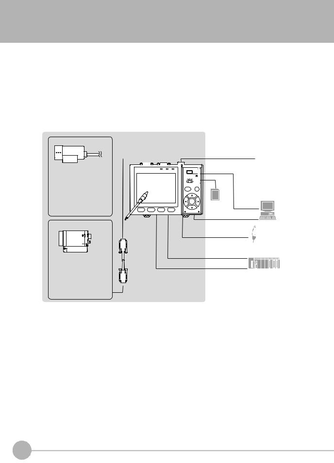
System Configuration
Basically, the ZFX-C is configured by the Controller and the camera.
Other external devices can be selected to be used in combination with the ZFX-C according to the user’s specific requirements.
Cameras with lighting
(cable built-in)
-Color camera ZFX-SC10_ ZFX-SC50_ ZFX-SC90_ ZFX-SC150_
-Monochrome camera ZFX-SR10_ ZFX-SR50_
Camera only
-Color camera ZFX-SC
-Monochrome camera ZFX-S
A CCTV lens and light source will be required.
|
Controller |
|
|
LCD monitor (option) |
||||||||||||||||||||
|
|
Monitor cable |
|
FZ-M08 (*2) |
||||||||||||||||||||
|
ZFX-C20/C25/C10H/C15H/C10/C15 (*5) |
|
|
|||||||||||||||||||||
|
|
FZ-VM |
|
|
|
|||||||||||||||||||
|
|
|
|
|
|
|
|
|
|
|
|
|
|
|
|
|
|
|
|
|
|
|
|
|
|
|
|
|
|
|
|
|
|
|
|
|
|
|
|
|
|
|
|
|
|
|
|
|
|
|
|
|
|
|
|
|
|
|
|
|
|
|
|
|
|
|
|
|
|
|
|
|
|
|
|
|
|
|
|
|
|
|
|
|
|
|
|
|
|
|
|
|
|
|
|
|
|
|
|
|
|
|
|
|
|
|
|
|
|
|
|
|
|
|
|
|
|
|
|
|
|
|
|
|
PC
2 3 4 |
SD Card (*4) |
USB |
|
|
Ethemet
Touch pen
(*1)
Console
ZFX-KP
(*3)
RS-232C cable ZFX-XPT_A PLC
RS-422 cable ZFX-XPT_B
Parallel I/O cable
ZFX-VP
Camera cable
ZFX-VS__/VSR__
*1: The Touch Pen (ZFX-TP) is supplied with the Controller.
*2: The same image as in the Controller's LCD monitor can be displayed in the LCD monitor (option). *3: The console can be used instead of the Controller's keys and menu buttons.
*4: Conforms to the SD Card “Physical layer specifications 1.01.” File format: FAT16
*5: Only connector 1 for camera 1 is provided on the ZFX-C10H/C15H/C10/C15.
14 |
ZFX-C |
ZFX-C User’s Manual |
|
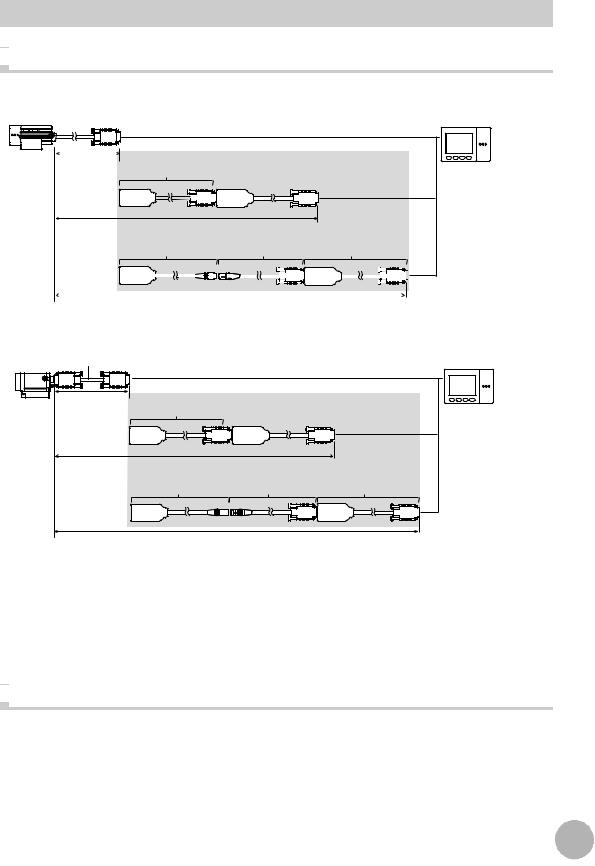
Options

 Extension cable for connecting cameras and the Controller
Cameras with Lighting
Extension cable
2 m |
ZFX-XC_A/XC_AR |
(cable built-in) |
3m/8m |
(*1)
5 to 18 m
ZFX-XEQ01 |
|
|
|
|
|
|
|
|
|
|
ZFX-XC_BR |
|
|
|
ZFX-XEQ02 |
|
|
|
|
|
||||||||||||||||||||||
|
|
0.2m |
|
|
|
|
|
|
|
|
|
|
|
|
15m/25m |
|
|
|
|
|
0.2m |
|
|
|
|
|
||||||||||||||||
|
|
|
|
|
|
|
|
|
|
|
|
|
|
|
|
|
|
|
|
|
|
|
|
|
|
|
|
|
|
|
|
|
|
|
|
|
|
|
|
|
|
|
|
|
|
|
|
|
|
|
|
|
|
|
|
|
|
|
|
|
|
|
|
|
|
|
|
|
|
|
|
|
|
|
|
|
|
|
|
|
|
|
|
|
|
18 to 27.4 m
Camera only
Camera cable
ZFX-VS/VSR
3 m/8 m |
ZFX-XC_A/XC_AR |
Extension cable |
|
|
|
||
|
3m/8m |
(*1,*2) |
|
|
|
|
|
8 to 19 m |
|
|
|
|
ZFX-XEQ01 |
ZFX-XC_BR |
ZFX-XEQ02 |
|
0.2m |
15m/25m |
0.2m |
19 to 28.4 m (*3) |
|
|
|
*1: Up to two ZFX-XC_A/XC-AR can be connected between the camera cable and the Controller.
*2: Up to two ZEX-XC_A/XC-AR can be connected to the camera cable as long as the total cable length between the Controller and the camera does not exceed 19 m.
*3: The total cable length between the Controller and the camera cannot exceed 28.4 m including camera cables. The ZFX-XC_A/XC_AR cannot be used in this combination.

 Optional lighting
The following optional lighting can be connected to ZFX-SC50_/SC90_.
•Bar lighting ZFV-LTL01
•Bar double-lighting ZFV-LTL02
•Bar low-angle lighting ZFV-LTL04
•Light Source for Through-beam Lighting ZFV-LTF01
USE BEFORE 1
|
|
15 |
|
ZFX-C User’s Manual |
ZFX-C |
||
|
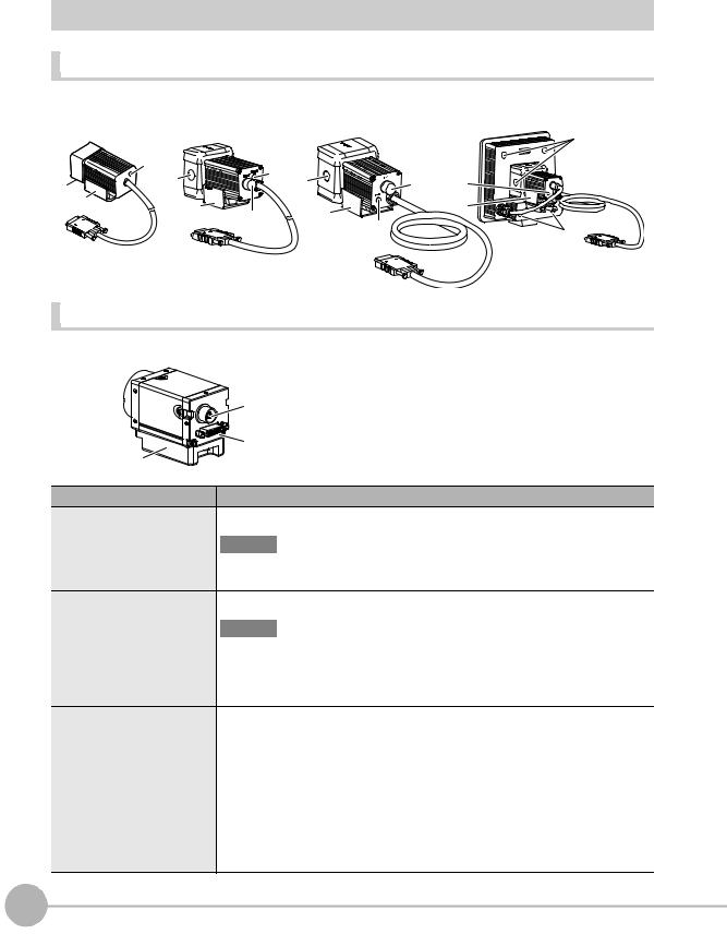
Part Names and Functions
Cameras
Cameras with lighting |
ZFX- |
ZFX-SC50_ |
|
ZFX-SC90_ |
|
ZFX-SC150_ |
SC10_/SR10_/SR50_ |
|
|
|
|
(2) |
|
|
|
|
|
|
(3) |
|
|
(3) |
|
|
(2) |
|
|
|
|
|
|
|
(2) |
(1) |
(3) |
|
(2) |
|
|
|||
(4) |
(4) |
|
|
|
(4) |
|
|
(4) |
|
||
|
|
(1) |
|
|
|
|
|
|
|
|
|
|
|
|
(3) |
|
(2) |
|
|
|
|
|
Camera only (C-mount type) |
ZFX-S/SC
|
(5) |
|
(6) |
(7) |
|
Name. |
Description |
(1) Optional lighting connector |
This connector is used to connect an optional lighting. (ZFX-SC50_/SC90_) |
Important
When no optional lighting is used, make sure that the connector is covered with the cap. If not, water-resistant performance will be deteriorated.
(2) Ventilation film |
This film prevents the front panel from condensation. |
Important
•Do not peel off or probe the ventilation film with a sharp-pointed object. If you do that the protective structure rating may no longer be satisfied.
•Do not cover the ventilation film rating. Doing so might cause the front panel to be condensed.
(3) |
Focus adjustment control |
This control is used for adjusting the focus of the image. |
|
|
|
(4) |
Mounting fixture |
This mounting fixture is used for fastening the camera when installing it. The mount- |
|
|
ing fixture can be installed on all of the four mounting surfaces. |
|
|
|
(5) |
Lighting connector |
This connector is used to connect external lighting (Strobe Controller: 3Z4S-LT |
|
|
MLEK-C100E1TSX). Note, however, that the Strobe Controller cannot be connected |
|
|
when the right angle camera cable is used. |
|
|
|
(6) |
Camera cable connector |
This connector is used for connecting to the Controller via a camera cable (ZFX-VS__/VSR__). |
|
|
|
(7) |
Camera mounting base |
This camera mounting base is fastened with screws to hold the camera in place. The camera |
|
|
mounting base can be installed on all of the four mounting surfaces. |
16 |
ZFX-C |
ZFX-C User’s Manual |
|
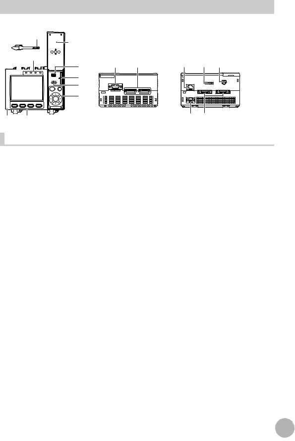
Controller
Front |
Operation |
Top |
Bottom |
(4) |
panel cover |
|
|
(1)
OMRON |
|
|
USB |
|
ZFX-C10 |
OUTPUT |
RUN |
ERROR ENABLE |
|
|
|
|
|
SD |
|
|
|
|
CARD |
|
|
|
ADJ |
|
|
|
|
MENU |
RUN |
|
(2) |
|
AUTO |
ESC |
|
|
|
|
SET |
1 |
2 |
3 |
4 |
|
|
|
|
|
PULL OPEN |
(1) |
(2) |
(1) |
(2) |
(3) |
(5) |
|
|
|
|
(6) |
|
CONSOLE |
|
RS-232C |
|
(7) |
ETHERNET |
|
|
|
|
|
PARALLEL1 |
PARALLEL0 |
|
RGB |
|
CAMERA2 |
CAMERA1 |
(8)
(9) |
(3) |
(4) (5) |
|
Front |
Name |
Function |
|
|
|
|
(1) |
Indicator |
“Measuring” indicator (RUN): Lights in green when in the RUN mode. |
|
|
Error indicator (ERROR): Lights in red when an error occurs. |
|
|
Judgment indicator (OUTPUT): Lights in orange when the judgment result is |
|
|
OK or NG according to the setting. (Note) |
|
|
Trigger indicator (ENABLE): Lights in blue when the ZFX-C is ready for the |
|
|
measurement trigger input. |
|
|
|
(2) |
LCD monitor/touch panel |
The LCD monitor displays setup menus and images captured from the cam- |
|
|
eras. Various settings can be made on the touch panel by tapping menu but- |
|
|
tons in the LCD monitor using the touch pen. |
|
|
|
(3) |
Function keys |
Specific functions are allocated to the Function keys. |
|
|
|
(4) |
Touch pen |
The touch pen is used to operate the touch panel. This pen can be attached to |
|
|
the Controller by tying its strap to the strap holder for the touch pen. |
|
|
|
(5) |
USB port |
This port is for connecting to a personal computer via a USB cable. |
|
|
|
(6) |
SD card slot |
This slot is for inserting the SD Card. |
|
|
When the SD Card is inserted, the SD mark is displayed at the top right of the |
|
|
screen. |
|
|
Blue SD mark: The SD card is inserted but not being accessed. |
|
|
Red SD mark: The SD card is being accessed. |
|
|
|
(7) |
Mode switch |
This switch selects the operation mode. |
|
|
MENU: Select this mode when setting measurement conditions. |
|
|
ADJ: Select this mode when adjusting setting parameters as necessary refer- |
|
|
encing the image and values displayed on the LCD monitor during con- |
|
|
tinuous test measurement (measurement without measurement data |
|
|
output to external devices). |
|
|
RUN: Select this mode when performing measurement. |
|
|
|
(8) |
Control keys |
These keys are used to perform operations without the use of the touch pen. |
|
|
|
(9) |
Strap holder for touch pen |
This holder is for attaching the touch pen. |
|
|
|
Note: The judgment result is output to the OR signal via the parallel interface.
USE BEFORE 1
|
|
17 |
|
ZFX-C User’s Manual |
ZFX-C |
||
|
Top |
Name |
Function |
|
|
|
|
(1) |
Monitor connector |
This connector is for connecting to the LCD monitor (option) via a monitor |
|
|
cable. |
|
|
|
(2) |
Camera connector |
This connector is for connecting to a camera. |
|
|
|
Bottom |
Name |
Function |
|
|
|
|
||
|
|
|
|
|
|
||
(1) |
Ethernet port |
This port is for connecting to a personal computer via a 100Base-TX/10Base-T |
|||||
|
|
cable. |
|
|
|
|
|
|
|
|
|
|
|
||
(2) |
RS-232C/422 connector |
This connector is for connecting to a PLC via an RS-232C or an RS-422 cable. |
|||||
|
|
|
p.14 |
|
|
|
|
|
|
|
|
|
|
|
|
|
|
|
|
|
|
|
|
(3) |
Console connector |
This port is for connecting to the Console. |
|
p.14 |
|
|
|
|
|
|
|||||
|
|
|
|
|
|||
|
|
|
|
|
|
|
|
(4) |
Power connector |
This connector is for connecting to the DC power supply. |
|
p.28 |
|||
|
|||||||
|
|
|
|||||
|
|
|
|
|
|
|
|
(5)Parallel port |
This port is for connecting to devices such as a PLC using the parallel cable. |
||||||
|
|
|
p.14, p.156 |
|
|
|
|
|
|
|
|
|
|
|
|
|
|
|
|
|
|
|
|
Important
•Attach the connector caps to connectors that are not in use to prevent dust or dirt from getting inside the connectors and to prevent the Controller from static electricity.
18 |
ZFX-C |
ZFX-C User’s Manual |
|
Mounting and Connecting Devices
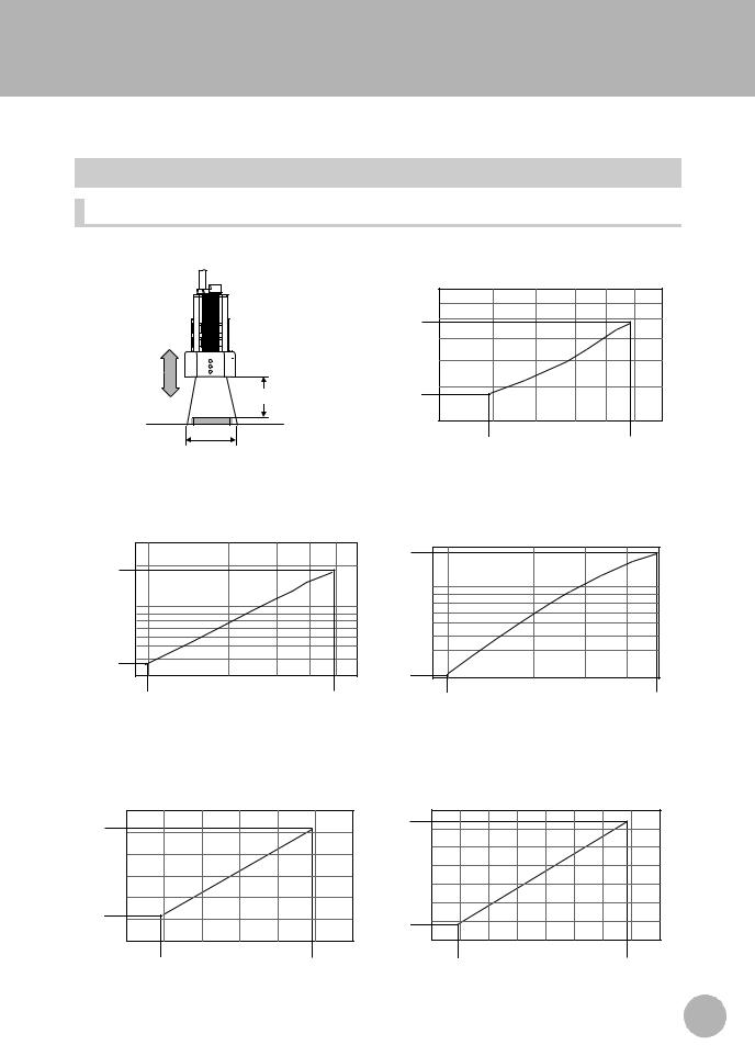
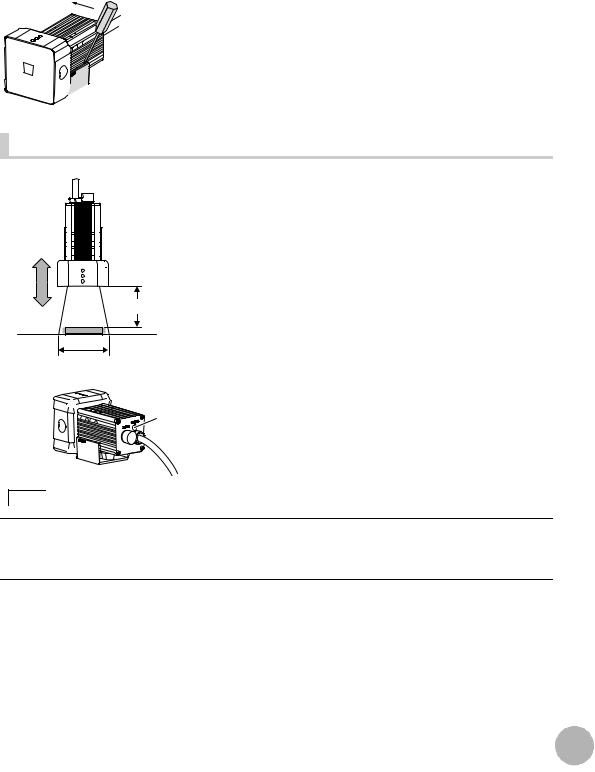
Installing Cameras
Camera with Lighting
Optical chart |
Setting distance (L)
Detection range (H)
 ZFX-SC10_/SR10_
Setting distance L (mm)
60 |
|
50 |
|
49 |
|
34 |
|
0 |
|
4 |
10 |
4.9 |
8.9 |
Detection range H (mm)
ZFX-SR50_ |
ZFX-SC50_ |
Setting distance L (mm) |
Setting distance L (mm) |
300 |
|
187 |
190 |
|
|
|
|
|
|
|
|
194 |
|
|
|
|
|
|
|
|
|
100 |
|
100 |
|
|
|
|
|
38 |
30 |
|
31 |
30 |
|
|
9 |
60 |
|
||
|
9.8 |
49 |
|
9.8 |
49 |
|
|
Detection range H (mm) |
|
|
Detection range H (mm) |
USE BEFORE 1
ZFX-SC90_ |
ZFX-SC150_ |
Setting distance L (mm) |
Setting distance L (mm) |
160 |
|
|
240 |
|
|
|
142 |
|
227 |
|
|
|
|
|
|
|
|
|
||
100 |
|
|
180 |
|
|
|
|
|
|
|
|
||
67 |
|
115 |
|
|
|
|
40 |
|
100 |
|
|
||
|
|
80 |
120 |
160 |
||
40 |
70 |
100 |
||||
|
|
|
||||
49 |
|
89 |
89 |
|
148 |
|
|
Detection range H (mm) |
|
Detection range H (mm) |
|||
|
|
19 |
|
ZFX-C User’s Manual |
Mounting and Connecting Devices |
||
|
Note
•The lens has a fixed focal point. The actual detection range and focal point vary from lens to lens, so adjust the distance to the measurement target after replacing the lens or camera.
•The camera mounting distance listed in the following tables is an approximate value. Mount the Camera so that the distance to the measurement target can be adjusted easily.
•If the object size and detection range are incompatible, use a combination of a camera (without lighting), standard CCTV lens and light source.
 Camera Only p.22

 Installing the mounting fixture
The mounting fixture can be installed on all of the four mounting surfaces.
ZFX-SR10R/SR50R/SC10R/SC50R/SC90R (robot cable type)
1
Bracket
2
Base
3
Install the mounting fixture with the protrusion on its base (black) aligned with the groove on the camera body.
Install the mounting fixture on the camera body with the bracket (silver) aligned with the base.
Tighten the base and the bracket with the provided screws (M3 x 6).
Tightening torque: 0.54N m
4 Fasten the base at the mounting position with screws.
Tightening torque
M4: 1.2 N m 1/4"-20UNC: 2.6 N m
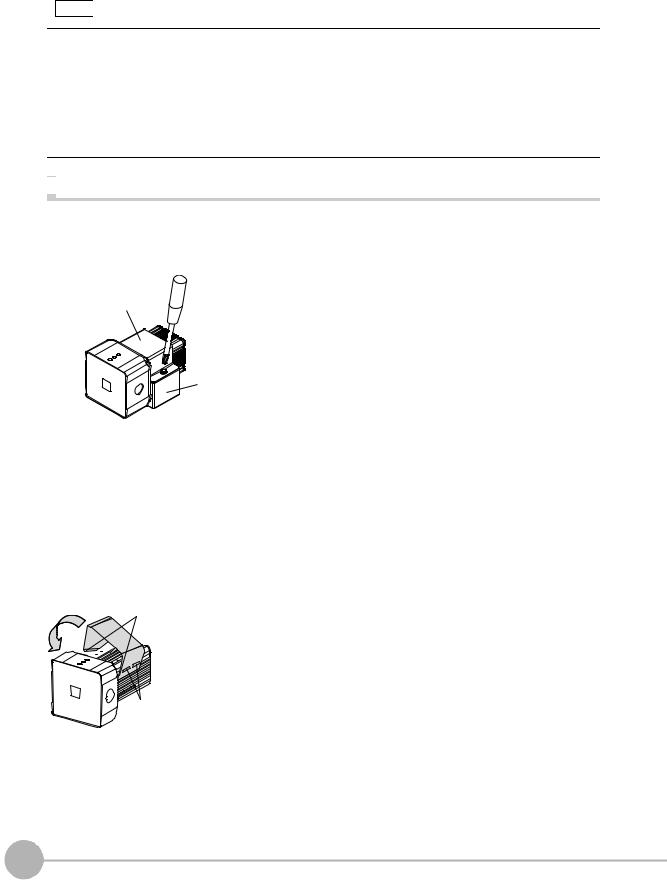
Except ZFX-SR10R/SR50R/SC10R/SC50R/SC90R (normal cable type)
Hooks
Mounting 

 fixture
Grooves on camera
1
2
Align the two hooks on one side of the mounting fixture with the two grooves on the camera body.
Push the other hook down until it is snapped into
place.
Make sure that the mounting fixture is firmly fixed on the camera.
20 |
Mounting and Connecting Devices |
ZFX-C User’s Manual |
|
3 Fasten the mounting fixture at the mounting location
with screws.
Tightening torque M4: 1.2 N•m
1/4”-20 UNC: 2.6 N•m
 Removal procedure
1 Insert a screwdriver into the gap (one of the two gaps) be-
tween the mounting fixture and the camera case, and re-
move the mounting fixture.


 Mounting fixture
Adjusting the camera focus |
1
Setting distance (L)
Detection range (H)
Focus |
|
|
adjustment |
2 |
|
control |
||
|
Note
Adjust the distance between the camera and the mea-
surement target and fasten the camera.
Refer to the optical chart and set the camera in a position so that the area to be checked is within the detection area (LCD monitor).
 Optical chart p.19
Turn the focus adjustment control to the left and right to adjust the focus.
First turn the focus adjustment control slightly to the left and right, to make sure that the Focus adjustment control is not at the upper or lower limit positions. Do not exert unnecessary force to turn the control at the upper or lower limit positions as this might damage the control.
(For ZFX-SC90_/SC150_, the control stops turning at the nearest position. It turns free at the farthest position.)
USE BEFORE 1
|
|
21 |
|
ZFX-C User’s Manual |
Mounting and Connecting Devices |
||
|

Camera Only
Optical chart |
The values in the following chart are approximations, and the Camera must be adjusted after it is mounted.
Lens model 3Z4S-LE
Camera distance A (mm)
ML-5018
10000  ML-3519
|
|
|
|
|
|
|
t0 |
t0 |
t0 |
|
|
|
|
|
|
|
|
|
ML-2514 |
||
|
|
|
|
|
|
|
|
|
|
|
|
|
|
|
|
|
|
|
t0 |
|
ML-1614 |
|
|
|
|
|
|
|
|
|
|
|
|
|
|
|
|
|
|
|
t0 |
|
ML-1214 |
|
|
|
|
|
|
|
|
|
|
|
1000 |
|
|
|
|
|
t1 |
|
|
|
|
|
|
|
|
|
t2 |
|
|
|
|
|
|
|
|
|
|
|
t0 |
|
|
ML-0813 |
|
|
|
|
|
|
|
|
|
|
||
|
|
|
|
|
t5 |
|
|
|
|
|
|
|
|
|
|
t1 |
|
|
|
|
|
|
|
|
|
|
|
|
|
|
|
|
|
|
|
|
t10 |
t2 |
t1 |
|
|
|
ML-0614 |
|
|
|
|
t0.5 |
t0 |
|
|
|||
|
|
|
t15 |
|
|
|
|
|
||
|
t35 |
t25 t20 |
t5 |
t2 |
|
|
|
|
||
|
|
|
|
|
|
|||||
|
|
t1 |
|
|
|
|
||||
|
t40 |
t30 |
t10 |
t1.5 |
|
|
|
|
||
|
t25 t20 t15 |
|
t5 |
|
|
|
|
|
||
|
|
t2 |
|
t0.5 |
|
|
|
|||
|
|
t15 t10 |
|
|
|
t1 |
|
|
|
|
100 |
t20 |
t5 |
|
|
|
|
|
|
||
|
|
|
|
|
t0.5 |
|
|
|
|
|
|
|
t10 |
|
t2 |
|
t0.5 |
|
|
|
t: Extension tube |
|
|
|
|
|
|
|
|
|
||
|
|
|
|
t1.5 |
t1 |
t1.5 |
|
|
|
|
|
|
|
|
|
|
|
|
|
Example |
|
|
|
|
|
|
|
t1 |
|
|
|
|
|
|
|
|
|
|
|
|
|
|
t0: Extension tube |
|
|
|
|
|
|
|
|
|
|
is not required. |
10 |
|
|
|
|
|
|
|
|
|
t5: 5-mm extension |
|
|
|
|
|
|
|
|
|
tube is required. |
|
|
1 |
|
10 |
|
|
|
100 |
|
1000 |
|
|
|
|
|
|
|
|
||||
Detection range (mm)
|
|
|
|
|
Lens model |
|
|
|
|
|
3Z4S-LE |
|
|
|
|
|
ML-10035 |
A (mm) |
10000 |
|
|
|
ML-7527 |
|
|
|
|
||
|
|
|
|
t0 |
|
|
|
|
t2 |
|
|
distance |
|
|
|
|
|
|
|
|
|
t0 |
|
|
|
|
t5 |
|
|
amera |
|
|
|
|
|
|
|
|
t10 |
|
|
|
|
|
t15 |
|
|
C |
|
t30 |
t20 |
|
|
|
t40 |
|
|
||
|
|
|
|
|
|
|
1000 |
|
|
|
|
|
t50 |
|
|
|
|
|
t60 |
|
|
t2 |
|
|
|
|
|
|
|
|
|
|
|
t5 |
|
|
|
|
|
t10 |
|
|
t50 |
|
|
t15 |
|
|
|
t20 |
|
|
|
|
t40 |
t30 |
|
|
|
|
100 |
|
|
|
|
|
1 |
|
10 |
100 |
1000 |
Detection range (mm)
22 |
Mounting and Connecting Devices |
ZFX-C User’s Manual |
|
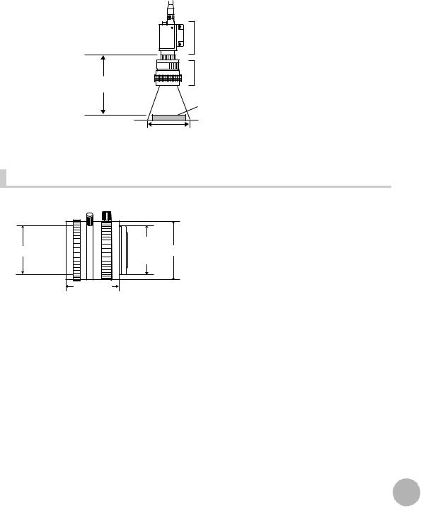
The X axis of the optical chart shows detection range L (mm), and the Y axis shows the camera distance A (mm). The curves on the optical chart show the relationship between the detection range and camera distance for each CCTV lens. The values are significantly different for each lens, so double-check the model of the lens before using the graph. The “t” values indicate the lengths of the Extension Tubes. The value “t0” shows the case where an Extension Tube is not required and the value “t5.0” shows the case where a 5-mm Extension Tube is used.
 Example
When a 3Z4S-LE ML-5018 CCTV Lens is being used and a detection range of 40 mm is required at the measurement target, a camera distance of 500 mm and 5-mm Extension Tube are required.
Camera
 Extension Tube t_ (mm)
Lens
Camera distance A (mm) 
Measurement object
Detection range L (mm)
Lenses and lens diameters |
|
1-32 UNF |
|
Filter thread |
(C-mount |
Max. dia. |
|
thread) |
|
|
Total length |
|
Lens |
Focal length |
Brightness |
Maximum outer diameter |
Total length |
Filter size |
|
|
|
|
|
|
3Z4S-LE ML-0614 |
6 mm |
F1.4 |
30 mm dia. |
30 mm |
M27 P0.5 |
|
|
|
|
|
|
3Z4S-LE ML-0813 |
8 mm |
F1.3 |
30 mm dia. |
34.5 mm |
M25.5 P0.5 |
|
|
|
|
|
|
3Z4S-LE ML-1214 |
12 mm |
F1.4 |
30 mm dia. |
34.5 mm |
M27 P0.5 |
|
|
|
|
|
|
3Z4S-LE ML-1614 |
16 mm |
F1.4 |
30 mm dia. |
24.5 mm |
M27 P0.5 |
|
|
|
|
|
|
3Z4S-LE ML-2514 |
25 mm |
F1.4 |
30 mm dia. |
24.5 mm |
M27 P0.5 |
|
|
|
|
|
|
3Z4S-LE ML-3519 |
35 mm |
F1.9 |
30 mm dia. |
29 mm |
M27 P0.5 |
|
|
|
|
|
|
3Z4S-LE ML-5018 |
50 mm |
F1.8 |
32 mm dia. |
37 mm |
M30.5 P0.5 |
|
|
|
|
|
|
3Z4S-LE ML-7527 |
75 mm |
F2.7 |
32 mm dia. |
42.5 mm |
M30.5 P0.5 |
|
|
|
|
|
|
3Z4S-LE ML-10035 |
100 mm |
F3.5 |
32 mm dia. |
43.9 mm |
M30.5 P0.5 |
|
|
|
|
|
|
USE BEFORE 1
|
|
23 |
|
ZFX-C User’s Manual |
Mounting and Connecting Devices |
||
|
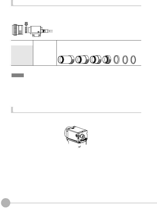
Extension Tubes |
One or more Extension Tubes can be inserted between the lens and the Camera to focus the Camera image. Use a combination of one or more of the seven tubes to achieve the required length.
Extension Tube
Model |
Maximum outer diameter |
Length |
|
|
|
3Z4S-LE ML-EXR |
31 dia. |
Set of 7 tubes |
Length: 40 mm 20 mm 10 mm 5 mm 2 mm 1 mm 0.5 mm
Important
•Do not use the 0.5-mm, 1.0-mm and 2.0-mm Extension Tubes attached to each other. Since these Extension Tubes are placed over the threaded section of the Lens or other Extension Tube, the connection may loosen when more than one 0.5-mm, 1.0-mm or 2.0-mm Extension Tube are used together.
•Reinforcement may be required for combinations of Extension Tubes exceeding 30 mm if the Camera is subject to vibration.
Installing the Camera Mounting Base |
The camera mounting base mounted on the bottom of the camera can be installed on all of the four mounting surfaces. To change the mounting surface, remove the three mounting screws (M2 x 6) from the camera.
Camera Mounting Base


• Tightening torque when fastening the camera mounting base at the mounting location M4: 1.2 N•m
1/4”-20 UNC: 2.6 N•m
24 |
Mounting and Connecting Devices |
ZFX-C User’s Manual |
|
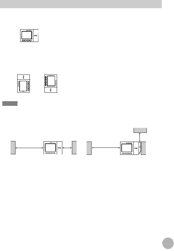
Installing the Controller
Installation Precautions
To improve heat radiation, install the Controller only in the orientation show below.
Right
Do not install the Controller in the following orientations.
Wrong Wrong
Important
•Install the Controller so that the distance between the Controller and other devices is at least the dimensions shown in the figure below to improve the ventilation.
When installing Controller only:
Min. |
Min. |
50 mm |
15 mm |
When installing the Controller With the Exhaust Unit attached:
Min. 15 mm
Min. 50 mm
•Keep the ambient temperature less than 50 °C. If the ambient temperature is higher than 50 °C, install a fan forced cooling system or an air conditioner to keep the temperature lower than 50 °C.
•Avoid mounting on a panel, in which high-voltage emitting devices are installed to prevent ZFX-C operation from being affected by noise.
•Allow at least 10 m between the Controller and power lines to keep noise at a low level in the operating environment.
USE BEFORE 1
|
|
25 |
|
ZFX-C User’s Manual |
Mounting and Connecting Devices |
||
|
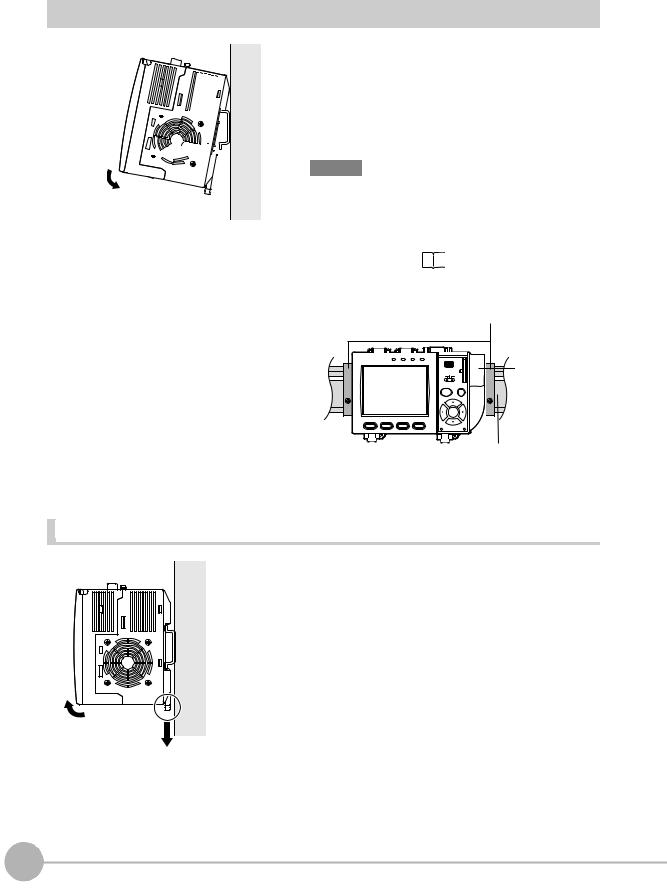
Installing on the DIN Track


 1
1 


 2
2
1
2
Hook the Controller’s upper hook onto the DIN track.
Push the Controller down onto the DIN track until its lower hook is snapped into place.
Important
•Attach the End Plate (sold separately) to both sides of the Controller on the DIN track.
•Attach the Exhaust Unit (supplied) to the Controller when installing other devices adjacently on the same DIN track
as the Controller. |
p.30 |
End Plate (sold separately)
PFP-M
OMRON |
|
OUTPUT RUN ERROR ENABLE |
USB |
|
Exhaust Unit |
|
ZFX-C10 |
|
|
SD |
|||
|
|
|
|
|
||
|
|
|
|
|
CARD |
|
|
|
|
|
ADJ |
|
|
|
|
|
MENU |
RUN |
|
|
|
|
|
AUTO |
ESC |
|
|
|
|
|
|
SET |
|
|
1 |
2 |
3 |
4 |
|
|
|
PULL OPEN
DIN track (sold separately)
PFP-100N (1 m)
PFP-50N (0.5 m)
PFP-100N2 (1 m)
Removing procedure |
1 |
2 |
1
2
Pull the Controller’s lower hook downwards.
Lift up the Controller from its bottom to remove it from the DIN track.
26 |
Mounting and Connecting Devices |
ZFX-C User’s Manual |
|
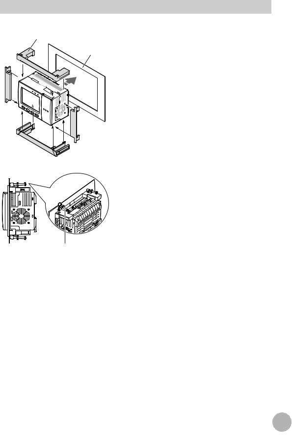
Mounting on a Panel
Panel mount adapters
Panel


 1
1


 3 2
3 2 


1 |
2 |
|
1 Install the long Panel Mount Adapters on the four holes on the Controller.
2 Install the short Panel Mount Adapters on the two holes on the long Panel Mount Adapter.
3 Install the Controller with Mount Adapters attached onto the panel from the front.
USE BEFORE 1
4
Mounting bracket
4 Hook the hooks of the mounting bracket onto the two
holes (two each at top and bottom) of the longer Mount Adapters and tighten the screws.
Tightening torque: 1.2 N•m.
5 Make sure that the Controller is firmly fixed on the panel.
|
|
27 |
|
ZFX-C User’s Manual |
Mounting and Connecting Devices |
||
|
Loading...