


 Loading...
NT-series
RS-232C/RS422 Interface Unit
Operation Manual
Produced October 1993
Notice:
OMRON products are manufactured for use according to proper procedures by a qualified operator and only for the purposes described in this manual.
The following conventions are used to indicate and classify precautions in this manual. Always heed the information provided with them. Failure to head precautions can result in injury to people or damage to the product.
DANGER! Indicates information that, if not heeded, is likely to result in loss of life or serious injury.
WARNING Indicates information that, if not heeded, could possibly result in loss of life or serious injury.
Caution Indicates information that, if not heeded, could result in relative serious or minor injury, damage to the product, or faulty operation.
OMRON Product References
All OMRON products are capitalized in this manual. The word “Unit” is also capitalized when it refers to an OMRON product, regardless of whether or not it appears in the proper name of the product.
The abbreviation “Ch,” which appears in some displays and on some OMRON products, often means “word” and is abbreviated “Wd” in documentation in this sense.
The abbreviation “PC” means Programmable Controller and is not used as an abbreviation for anything else.
Visual Aids
The following headings appear in the left column of the manual to help you locate different types of information.
Note Indicates information of particular interest for efficient and convenient operation of the product.
1, 2, 3... 1. Indicates lists of one sort or another, such as procedures, checklists, etc.
©OMRON, 1993
!
|
|
|
|
||
|
|
||||
|
|
|
|||
|
|
|
|||
|
|
||||
|
|
! |
" |
||
|
|
|
|
||
! |
|
||||
|
! |
|
|
||
|
## $ |
|
|||
|
% |
|
|||
|
|
|
|
||
" ! |
# |
||||
|
! |
|
" |
||
|
&$ |
" |
|||
|
% |
' |
|||
|
|
|
|
||
$ |
|
||||
|
|
|
|||
|
|
|
|||
|
(# & # ) |
|
|||
|
* |
|
+ |
||
% |
|
|
|
||
$" |
&& ! |
|
|||
, $ % ! |
|
||||
, $ *- |
" |
||||
' |
|
|
|
||
& |
&& ! |
|
|||
|
-# |
|
|
||
# |
|
|
|
||
|
&& ! |
( |
|||
. |
/ # - |
' |
|||
. |
- *- % ! |
' |
|||
. |
) $ 0 -! |
|
|||
. |
- 0 ) # |
|
|||
. |
0 !# % 0 |
|
|||
) |
|
|
|
||
&$ * " & |
|
%% |
|||
" |
1 * |
|
|||
" |
* |
|
. |
||
( |
|
|
|
||
|
+,- |
" |
'% |
||
+ |
/ |
&$ $ * & - ) |
|
||
+ |
-,#$ / |
|
|||
$$!
2 |
! |
+ |
|
|
,# |
. |
|
|
0 ,# -! |
. |
|
0 |
! # $ |
|
. |
. |
/ |
## |
|

About this Manual:
This manual describes the installation and operation of the NT-series RS-232C/RS422 Interface Unit and includes the sections described below.
Please read this manual carefully and be sure you understand the information provided before attempting to install and operate the NT-series RS-232C/RS422 Interface Unit.
Section 1 describes the role and operation of the RS232C/RS422 Interface Unit, and its relationship to the PT features and provides a command reference table.
Section 2 describes how to connect the RS-232C Interface Unit to the PT and the PT to the host computer.
Section 3 describes how to set the RS-422 Interface Unit and how to connect the PT to the host computer. Installation of the RS-422 Interface Unit in the PT and the PT DIP switch settings are identical to the RS-232C Interface Unit.
Section 4 describes RS-232C/RS-422 Interface Unit communication procedures and how to use the commands.
Section 5 describes the functions of the operating commands and how to use them. The operating commands allows control of the PT by the host computer and notification of PT operations to the host computer.
Section 6 describes the functions of the terminal commands and how to use them. Terminal commands allow the display of information from the host computer as text and graphics, independently of the screens stored in the PT.
Section 7 describes the functions of the online transfer commands to transfer screen and memory table data between the host computer and PT. The commands cannot be used with PTs fitted with an EPROM or EEPROM image memory.
Section 8 provides some sample programs using the Transfer commands. Refer to these sample programs for actual information on using the commands.
Section 9 describes the cause of errors and possible remedies.
This manual also contains four Appendices which provide information on communication specifications, preparing RS-232C/RS422 Connector Cables, and connections using different cable types.
WARNING Failure to read and understand the information provided in this manual may result in personal injury or death, damage to the product, or product failure. Please read each section in its entirety and be sure you understand the information provided in the section and related sections before attempting any of the procedures or operations given.
0
-$ , $ # ! $ 3 #$! $ *-
! 4 ,#
|
|
|
|
|
|
|
|
|
|
! |
" |

|
Section 1-1 |
|
|
|
|
1-1 Getting Started
|
To ensure that the RS-232C/RS-422 Interface Unit works correctly, carefully ob- |
|
serve the following when positioning and handling it. |
Location |
Do not install the RS-232C/RS-422 Interface Unit in a location subject to the fol- |
|
lowing conditions: |
|
∙ Dust, chemicals, or steam |
|
∙ Severe temperature fluctuations |
|
∙ High humidity and condensation |
|
∙ Direct sunlight |
|
∙ Strong electrical or magnetic fields |
|
∙ Poor ventilation |
|
∙ Severe vibration |
Handling |
Do not: |
|
∙ Subject the Unit to strong shocks or vibrations |
|
∙ Position the Unit’s PCB downward |
|
∙ Touch the Unit’s PCB |
|
∙ Put heavy objects on the unit |
|
∙ Supply a voltage different from the specified voltage |
|
To ensure that the RS-232C/422 Interface Unit works correctly, carefully follow |
|
the advice below on positioning and handling the unit. |

|
|
|
|
|
Section 1-1 |
|||
System Configuration |
The equipment and parts required |
to configure the system to use the |
|
|||||
|
|
RS-232C/RS-422 Interface Unit are shown below. |
|
|
|
|||
|
|
|
|
|
|
|
|
|
Programmable Terminal |
Screen-data |
Host I/F |
System |
Support |
Expansion I/O |
System |
||
|
|
Memory Board/ |
Unit |
ROM |
tools |
Unit |
Key Unit |
|
|
|
Screen Memory |
|
|
|
|
|
|
|
|
|
|
|
|
|
|
|
NT20M/ |
Monochrome LCD: |
Screen Memory |
RS-232C |
NT20M- |
NT20M- |
For connection |
NT-FK200 |
|
NT2000M |
NT20M-DT121-V2 |
SRAM/32 KB: |
I/F Unit |
SMR01- |
ZASAT- |
to a without |
for con- |
|
|
NT600M- |
E |
EV4: |
touch-panel |
nection to |
|||
|
Touch-panel Model |
RAM22-15 |
||||||
|
LK201 |
|
3.5-inch |
model |
NT2000M |
|||
|
NT20M-DN121-V2 |
SRAM/128 KB: |
|
|||||
|
|
|
(2DD) and |
|
|
|
||
|
Without Touch- |
RAM13-10 |
RS-422 |
|
NT20M-FK210 |
|
|
|
|
|
5.25-inch |
|
|
||||
|
panel Model |
EPROM/64 KB: |
I/F Unit |
|
12-key Function |
|
|
|
|
|
(2HD) |
|
|
||||
|
|
ROM-KD-B |
NT600M- |
|
Key Unit |
|
|
|
|
Backlit replaceable: |
|
disks |
|
|
|||
|
EPROM/128 KB: |
LK202 |
|
|
|
|
||
|
|
|
|
|
|
|
||
|
NT20M-DT131 |
ROM13-12B |
|
|
|
|
|
|
|
Touch-panel Model |
EEPROM/32 KB: |
|
|
|
|
|
|
|
NT20M-DN131 |
EER22-20 |
|
|
|
|
|
|
|
Without Touch- |
|
|
|
|
|
|
|
|
panel Model |
|
|
|
|
|
|
|
|
|
|
|
|
|
|
|
|
|
Large size: |
|
|
|
|
|
|
|
|
NT2000M- |
|
|
|
|
|
|
|
|
DT131/DN131 With- |
|
|
|
|
|
|
|
|
out Touch-panel |
|
|
|
|
|
|
|
|
Model |
|
|
|
|
|
|
|
|
|
|
|
|
|
|
|
|
NT600M |
Monochrome LCD: |
Screen-data |
|
NT600M- |
|
For connection |
--- |
|
|
NT600M-DT122 |
Memory Board |
|
SMR01- |
|
to a without |
|
|
|
|
|
EV1 |
|
touch-panel |
|
|
|
|
Touch-panel Model |
IC socket type: |
|
|
|
|
||
|
|
|
|
model |
|
|
||
|
NT600M-DF122 |
NT600M-MP251 |
|
|
|
|
|
|
|
|
|
|
|
|
|
||
|
Function Key Model |
64K-byte SRAM: |
|
|
|
NT600M-FK210 |
|
|
|
|
NT600M-MR641 |
|
|
|
12-key Function |
|
|
|
|
128K-byte |
|
|
|
Key Unit |
|
|
|
|
SRAM: |
|
|
|
|
|
|
|
|
NT600M-MR151 |
|
|
|
|
|
|
|
|
256K-byte |
|
|
|
|
|
|
|
|
SRAM: |
|
|
|
|
|
|
|
|
NT600M-MR251 |
|
|
|
|
|
|
|
|
Screen Memory |
|
|
|
|
|
|
|
|
The screen |
|
|
|
|
|
|
|
|
memory chip |
|
|
|
|
|
|
|
|
must be inserted |
|
|
|
|
|
|
|
EL display: |
|
|
|
|
|
|
|
|
in the IC socket. |
|
|
|
|
|
|
|
|
NT600M-DT211 |
|
|
|
|
|
|
|
|
Screen data is |
|
|
|
|
|
|
|
|
Touch-panel Model |
written with a |
|
|
|
|
|
|
|
NT600M-DN211 |
PROM writer. |
|
|
|
|
|
|
|
Without Touch- |
|
|
|
|
|
|
|
|
panel Model |
|
|
|
|
|
|
|
|
|
|
|
|
|
|
|
|

|
|
|
Section 1-1 |
||
Table of Commands |
|
|
|
|
|
Polling Commands |
|
|
|
|
|
|
|
|
|
|
|
Type |
Command |
Name |
|
Page |
|
|
|
|
|
|
|
Polling |
[ESC] @ |
Start Polling (RS-422 I/F Unit Read) |
|
25 |
|
|
|
|
|
|
|
|
[ESC] A |
End Polling (RS-422 I/F Unit Read) |
|
25 |
|
Operating Commands |
|
|
|
|
|
|
|
|
|
|
|
Type |
Command |
Name |
|
Page |
|
|
|
|
|
|
|
Screen control |
[ESC] 0 |
Display Specified Screen |
|
32 |
|
|
|
|
|
|
|
|
[ESC] X |
Request Screen Number |
|
32 |
|
|
|
|
|
|
|
Memory table op- |
[ESC] B |
Write Character-string Memory Table |
|
32 |
|
eration |
|
|
|
|
|
[ESC] C |
4-digit Write Numeral Table |
|
33 |
|
|
|
|
|
|||
|
|
|
|
|
|
|
[ESC] D |
8-digit Write Numeral Table |
|
33 |
|
|
|
|
|
|
|
|
[ESC] / |
Copy Memory Table |
|
33 |
|
|
|
|
|
|
|
Lamp and Touch |
[ESC] K |
Lamp and Touch Switch Display (Bit Specification) |
|
34 |
|
Switch Display |
|
|
|
|
|
[ESC] Q |
Lamp and Touch Switch Display (Address Specification) |
|
34 |
|
|
|
|
|
|||
|
|
|
|
|
|
|
[ESC] R |
Lamp and Touch Switch Display Status Enquiry |
|
35 |
|
|
|
|
|
|
|
Touch Switch and |
[ESC] U |
Touch Switch and Function Key Disable |
|
35 |
|
Function Key Input |
|
|
|
|
|
[ESC] V |
Touch Switch and Function Key Enable |
|
35 |
|
|
|
|
|
|||
|
|
|
|
|
|
System Control |
[ESC] O |
Backlight Color Switching (NT20M, NT2000M) |
|
36 |
|
|
|
|
|
|
|
|
[ESC] P |
Screen Display Control |
|
36 |
|
|
|
|
|
|
|
|
[ESC] T |
Buzzer Control |
|
36 |
|
|
|
|
|
|
|
|
[ESC] W |
Mode Switch Enable |
|
36 |
|
|
|
|
|
|
|
|
[ESC] Z |
PT Battery Status Enquiry |
|
37 |
|
|
|
|
|
|
|
|
[ESC] ] |
Initialize Display History |
|
37 |
|
|
|
|
|
|
|
|
[ESC] ^ |
Alarm Output Control |
|
37 |
|
|
|
|
|
|
|
|
[ESC] _ |
Display Mode Control (NT600M-D 122 Read) |
|
37 |
|
|
|
|
|
|
|
Notification |
[ESC] Y |
Screen Number Response |
|
38 |
|
|
|
|
|
|
|
|
[ESC] E |
4-digit Number Input Notify |
|
38 |
|
|
|
|
|
|
|
|
[ESC] F |
8-digit Number Input Notify |
|
38 |
|
|
|
|
|
|
|
|
[ESC] G |
Function Key Number Output |
|
39 |
|
|
|
|
|
|
|
|
[ESC] H |
Touch Switch Number Output |
|
39 |
|
|
|
|
|
|
|
|
[ESC] I |
Function Key Bit Output |
|
39 |
|
|
|
|
|
|
|
|
[ESC] J |
Touch Switch Bit Output |
|
40 |
|
|
|
|
|
|
|
|
[ESC] S |
Lamp/Touch Switch Display Status Response |
|
40 |
|
|
|
|
|
|
|
|
[ESC] [ |
PT Battery Status Response |
|
41 |
|

|
Section 1-2 |
|||||
Terminal Commands |
|
|
|
|
||
|
|
|
|
|
|
|
|
Type |
Command |
Name |
|
Page |
|
|
|
|
|
|
|
|
Delete |
|
[ESC] & |
Clear Screen |
|
44 |
|
|
|
|
|
|
|
|
Character Size |
[ESC] ) |
Character Specify Size |
|
44 |
|
|
|
|
|
|
|
|
|
|
|
[ESC] |
Specify Character Enlargement |
|
44 |
|
|
|
|
|
|
|
|
Character Display |
[ESC] ! |
Normal Display |
|
45 |
|
|
Attributes |
|
|
|
|
|
|
[ESC] ” |
Set Inverse Display |
|
45 |
|
||
|
|
|
|
|||
|
|
|
|
|
|
|
|
|
[ESC] # |
End Inverse Display |
|
45 |
|
|
|
|
|
|
|
|
|
|
[ESC] $ |
Set Flashing Display |
|
45 |
|
|
|
|
|
|
|
|
|
|
[ESC] % |
End Flashing Display |
|
46 |
|
|
|
|
|
|
|
|
Character String |
[ESC] + |
Set Cursor Position |
|
46 |
|
|
Display |
|
|
|
|
|
|
|
[ESC] 4 |
Specify Displayed Characters |
|
46 |
|
|
|
|
|
|
|||
|
|
|
|
|
|
|
Graphic Display |
[ESC] 7 |
Draw Polyline |
|
47 |
|
|
|
|
|
|
|
|
|
|
|
[ESC] 8 |
Draw Circle |
|
47 |
|
Online Transfer Commands |
|
|
|
|
||
|
|
|
|
|
|
|
|
Type |
Command |
Name |
|
Page |
|
|
|
|
|
|
|
|
Start/Stop Online |
[ESC] x |
Online Transfer Start |
|
50 |
|
|
Transfer |
|
|
|
|
|
|
[ESC] y |
Online Transfer End |
|
50 |
|
||
|
|
|
|
|||
|
|
|
|
|
|
|
Set Transfer from |
[ESC] s |
Specify Transfer Screen Number (Host Computer to PT) |
|
50 |
|
|
PT to Host Comput- |
|
|
|
|
|
|
[ESC] u |
Specify Transfer Non-screen Data (Host Computer to PT) |
|
51 |
|
||
er |
|
|
|
|||
|
|
|
|
|
|
|
Data Type Notifica- |
[ESC] r |
Transfer Screen Number Notify (PT to Host Computer) |
|
51 |
|
|
tion |
|
|
|
|
|
|
|
[ESC] t |
Transfer Non-screen Data Notify (PT to Host Computer) |
|
52 |
|
|
|
|
|
|
|||
|
|
|
|
|
|
|
Data Transfer and |
[ESC] z |
Transfer Data |
|
52 |
|
|
Result Notification |
|
|
|
|
|
|
[ESC] } |
Acknowledged |
|
52 |
|
||
|
|
|
|
|||
|
|
|
|
|
|
|
|
|
[ESC] ~ |
Not-acknowledged |
|
53 |
|
|
|
|
|
|
|
|
|
|
Note The commands are only applicable to NT20M or NT600M PTs fitted with SRAM |
||||
|
|
|
memory. |
|
|
|
1-2 |
RS-232C/RS-422 Interface Unit |
|
|
|
||
|
|
|
The RS-232C/RS-422 Interface Unit supports three command types for control |
|||
|
|
|
of the PT by the host computer. |
|
|
|
Operating Commands |
Commands for control of the PT display, status, and notification during run op- |
|||||
|
|
|
eration. The commands write screen displays and data, and make enquiries. |
|||
|
|
|
The commands notify the host computer of operations at the PT. |
|||
Terminal Commands |
Commands for use of the PT as a terminal for the host computer. The commands |
|||||
|
|
|
allow display of information from the host computer as text and graphics, inde- |
|||
pendently of the screens stored in the PT. The commands are used to handle unforeseen events.
Online Transfer Commands Commands for transfer of screen and memory table data between the host computer and PT.
Types of data transferred:
∙Screen data (1 screen/all screens)
∙System memory
∙Memory table data
∙Mark data
%
|
Section 1-3 |
|
∙ Display history data by sequence or by frequency (from PT to host computer |
|
only) |
|
The online transfer commands allow batch data transfer which simplifies system |
|
modification and maintenance. |
|
Main applications: |
|
∙ Partial screen modification |
|
∙ Screen switching when setting up a production line |
|
∙ Data backup |
1-3 |
System Configuration |
|
|
|
The system configuration using the RS-232C Interface Unit or the RS-422 Inter- |
|
|
face Unit is shown below. |
PT |
|
The PT displays monitored data from the production line and instructions to the |
|
|
factory workers. It notifies the host computer of switch ON/OFF settings and nu- |
|
|
meric inputs. |
Host Computer |
Controls the PT display and status. Processes data notified by the PT. |
|
Support Tool |
Creates the screens for display by the PT. |
|
RS-232C Interface Unit System Configuration
Create a one-to-one connection between the host computer and PT when the RS-232C Interface Unit is used.
Host computer: Personal computer or FA computer
|
|
|
|
|
|
|
|
|
|
|
|
|
|
|
|
|
IBM PC/AT or |
NT-series |
|
|
|
|
|
|
|
|
|
|
|
|
|
|
|
|
|
||
|
|
|
|
|
|
|
|
|
|
|
|
|
|
|
|
|
||
|
|
|
|
|
|
|
|
|
|
|
|
|
|
|
|
|
||
|
|
|
|
|
|
|
|
|
|
|
|
|
|
|
|
|
||
|
|
|
|
|
|
|
|
|
|
|
|
|
|
|
|
|
||
|
|
|
|
|
|
|
|
|
|
|
|
|
|
|
|
|
||
|
|
|
|
|
|
|
|
|
|
|
|
|
|
|
|
|
||
|
|
|
|
|
|
|
|
|
|
|
|
|
|
|
|
|
||
|
|
|
|
|
|
|
|
|
|
|
|
|
|
|
|
|
compatible |
|
|
|
|
|
|
|
|
|
|
|
|
|
|
|
|
|
|
Support Tool |
|
|
|
|
|
|
|
|
|
|
|
|
|
|
|
|
|
|
|
RS-232C cable (max. 15 m)
RS-232C
Interface
Unit
RS-232C cable
'

|
Section 1-3 |
|
|
|
|
RS-422 Interface Unit System Configuration
Connect a single host computer to a maximum of 16 PTs when the RS-422 Interface Unit is used.
Host computer: Personal computer or FA computer
|
B500-AL004 |
|
|
Link Adaptor |
NT-series |
|
IBM PC/AT or |
|
|
compatible |
Support Tool |
|
RS-422 cable |
|
B500-AL001 |
PT |
|
Link Adaptor |
|
|
|
RS-232C cable |
|
RS-422 |
|
|
Interface Unit |
|
|
B500-AL001 |
PT |
|
|
|
|
Link Adaptor |
|
|
RS-422
Interface Unit
#

|
Section 1-4 |
|
|
|
|
1-4 Before Operating
Follow the procedure indicated below before operating a PT with
RS-232C/RS-422 Interface Unit installed.
PC
Check and change the host computer connections.
Refer to the appropriate
Host Computer Manual
Create the host computer program.
Refer to the appropriate
Host Computer Manual
PT
Check the PT power supply and ground cable connections.
Refer to the appropriate
PT Manual
Install the RS-232C/RS422
Interface Unit.
Refer to page 12.
Check and set the PT and RS-232C/RS422 Interface Unit.
Refer to page 13.
Connection to the host computer.
Refer to page 15.
Check settings and communications.
Transfer screen data
Refer to the appropriate
PT Manual
Support Tool
Create screens with the Support Tool
Refer to the NT-series
Support Tool Manual.
Trial operation
)

|
|
Section 1-4 |
||
Reference Manuals |
The NT20M/NT2000M Series and NT600M Series are covered in the six |
|
||
|
manuals described below. |
|
|
|
|
|
|
|
|
Name of Manual |
Contents |
|
Manual No. |
|
|
|
|
|
|
NT20M/NT2000M Operation |
This manual provides specifications, functions, and operating |
|
V001 |
|
Manual |
instructions for the NT20M and NT2000M Programmable Terminals. |
|
|
|
|
|
|
|
|
NT600M Operation Manual |
This manual provides specifications, functions, and operating |
|
V002 |
|
|
instructions for NT600M Programmable Terminals. |
|
|
|
|
|
|
|
|
NT-series Host Interface Unit |
This manual covers the commands, controls, and communications |
|
V003 |
|
Operation Manual |
specifications for operating the NT20M and the NT600M. Refer to |
|
|
|
|
this manual when programming host computer communications. |
|
|
|
|
|
|
|
|
NT20M/NT600M Support Tool |
This manual covers methods for creating screens, including screen |
|
V004 |
|
Operation Manual |
data preparation, switches, lights, and alarms. |
|
|
|
|
|
|
|
|
NT-series Host Interface Unit |
This manual covers the Direct Connection feature which has been |
|
V015 |
|
Direct Connection Operation |
added to the Host Interface Unit. |
|
|
|
Manual |
|
|
|
|
|
|
|
|
|
NT-series RS-232C/RS-422 |
This manual covers the commands, controls, and communications |
|
V016 |
|
Interface Unit Operation Manual |
specifications for operating the NT20M and the NT600M with the |
|
|
|
|
RS-232C/RS-422 Interface Unit. Refer to this manual when |
|
|
|
|
programming host computer communications. |
|
|
|
(
!
-$ , $& $ $ *- $ *- $ $ !
|
! |
|
|
|
## $ |
|
|
|
|
## |
|
|
|
&$ |
|
|
*- &$ |
|
|
|
% |
|
|
|
|
% ! |
|
|
|
* 2 |
|
|
Section 2-2 |
|
|
|
|
2-1 Components
Before explaining how to connect the RS-232C Interface Unit to the PT, the names and functions of the RS-232C Interface Unit components are described.
Description of Components
The names and functions of the components of the RS-232C Interface Unit are shown in the diagram below.
NT600M-LK201 RS-232C Interface Unit
RS-232C Interface Unit front face
Switch cover:
Open this cover to reveal the DIP switches (SW4) which set the basic operation of the RS-232C Interface Unit.
Host Interface RS-232C Connector: |
RS-232C Interface Unit rear |
|
|
Connector for connection to the host computer. |
face |
Unit connector for connection to the PT.
2-2 Installing the RS-232C Interface Unit
The methods of installing the RS-232C Interface Unit in the PT and setting the
DIP switches are described below.
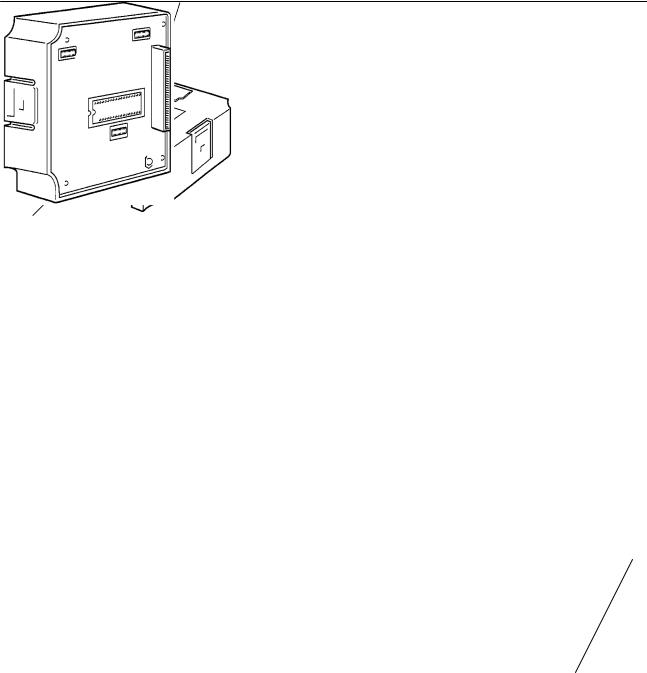
2-2-1 Installation
Turn the cut-out in the RS-232C Interface Unit to the left and push the Unit in until a “click” is heard.
In difficult-to-connect situations move the Unit when connecting the RS-232C
Interface Unit.
Note Turn off the PT power supply when installing or removing the RS-232C/RS-422 Interface Unit.

|
Section 2-2 |
|
|
|
|
Installation in the NT600M
NT600M
Rear face
Cut-out
Removal from the NT600M Hold the RS-232C/RS-422 Interface Unit by the indentations at each side, press inwards and pull out the Unit.
NT600M
Rear face
Rear face
2-2-2 RS-232C Interface Unit Switch Settings
Set the communication conditions with the RS-232C Interface Unit DIP switches (SW4).
The DIP switches are under Switch cover the switch cover on the front
of the Interface Unit.
1 2 3 4 5 6 7 8 9 0
SW4-1 Data Bits |
Data bits (see note following the switch settings) |
|
|
|
ON: 8 bits, OFF: 7 bits |
|
|
SW4-2 Stop Bits |
Stop bits (see note following the switch settings) |
|
|
|
ON: 1 bit, OFF: 2 bits |
|
|
SW4-3/4 Parity Check |
Also see note following the switch settings. |
|
|
|
|
|
|
|
None |
Even |
Odd |
|
|
|
|
|
SW4-3: ON |
SW4-3: OFF |
SW4-3: OFF |
|
SW4-4: ON |
SW4-4: ON |
SW4-4: OFF |
SW4-5/6 Flow Control |
|
|
|
|
|
|
|
|
|
|
|
|
None |
RS/CS control |
XON/XOFF control |
|
|
|
|
|
SW4-5: ON |
SW4-5: OFF |
SW4-5: OFF |
|
SW4-6: OFF |
SW4-6: ON |
SW4-6: OFF |

|
|
|
|
Section 2-2 |
|||
SW4-7/8/9 Baud Rate |
Sets the PT Baud Rate |
|
|
|
|
||
|
|
Set to the maximum baud rate supported by both the PT and the host computer. |
|||||
|
|
However, the baud rate must be set to the same value on both devices. |
|||||
|
|
|
|
|
|
|
|
19,200 bps |
9,600 bps |
4,800 bps |
2,400 bps |
1,200 bps |
600 bps |
300 bps |
|
|
|
|
|
|
|
|
|
SW4-7: ON |
SW4-7: ON |
SW4-7: ON |
SW4-7: OFF |
SW4-7: OFF |
SW4-7: OFF |
SW4-7: OFF |
|
SW4-8: ON |
SW4-8: OFF |
SW4-8: OFF |
SW4-8: ON |
SW4-8: ON |
SW4-8: OFF |
SW4-8: OFF |
|
SW4-9: OFF |
SW4-9: ON |
SW4-9: OFF |
SW4-9: ON |
SW4-9: OFF |
SW4-9: ON |
SW4-9: OFF |
|
SW4-10 Not Used
Note Set the data, stop, parity, flow control, and baud rate bits to match one of the combinations as shown in the following.
7 data bits, Even parity, 2 stop bits |
8 data bits, No parity, 2 stop bits |
|
|
7 data bits, Odd parity, 2 stop bits |
8 data bits, No parity, 1 stop bit |
|
|
7 data bits, Even parity, 1 stop bit |
8 data bits, Even parity, 1 stop bit |
|
|
7 data bits, Odd parity, 1 stop bit |
8 data bits, Odd parity, 1 stop bit |
Caution Turn off the power supply before setting the DIP switches.
2-2-3 PT Switch Settings
NT20M |
NT2000M |
Switch cover
Switch cover
NT600M
Switch cover
|
The DIP switches are under the switch |
1 2 3 4 5 6 7 8 |
cover on the rear of the PT. |
SW1-1 |
Automatic release after communication error. |
|
ON: No automatic release |
|
OFF: Automatic release |
SW1-2 |
Enable/Disable host RUN |
|
ON: Disable |
|
OFF: Enable |
SW1-3 |
Reserved for system use. Always set ON. |
SW1-4/5 |
Not used |
SW1-6 |
Mode change Enable/Disable (NT20M/NT2000M/NT600M) |
|
ON: Enable |
|
OFF: Disable |

|
|
|
|
Section 2-3 |
||
|
|
|
|
|
|
|
SW1-7 |
|
|
Not used |
|
|
|
SW1-8 |
|
|
Communication specification setting |
|||
|
|
|
|
Always set OFF when the RS-232C Interface Unit is installed. |
||
|
|
|
Note Turn off the power supply before setting the DIP switches. |
|||
|
|
|
|
SW1-8 can be set ON or OFF when the RS-422 Interface Unit is installed. |
||
2-3 |
Host Connections |
|
|
|||
|
|
|
|
Connect a PT with an RS-232C Interface Unit installed to the host computer with |
||
|
|
|
|
an RS-232C cable. |
|
|
|
|
|
|
RS-232C connection allows a single PT to be connected to the host. |
||
|
|
|
|
A computer or other control device with a built-in RS-232C interface is a suitable |
||
|
|
|
|
host for connection to the PT. |
||
2-3-1 Host Computer Communication Settings |
||||||
|
|
|
|
Set the host communication conditions according to the following table. |
||
|
|
|
|
|
|
|
|
|
|
|
Item |
Setting |
|
|
|
|
|
|
|
|
|
|
|
|
Baud rate |
Set to the same baud rate as the PT: 300, 600, 1200, 2400, |
|
|
|
|
|
|
4800, 9600, 19200 |
|
|
|
|
|
|
|
|
|
|
|
|
Data bits |
7 bits/8 bits |
|
|
|
|
|
|
|
|
|
|
|
|
Stop bits |
1 bit/2 bits |
|
|
|
|
|
|
|
|
|
|
|
|
Parity |
Even, Odd, None |
|
|
|
|
|
|
|
|
|
|
|
|
Flow control |
RS/CS control |
|
|
|
|
|
|
XON/XOFF control |
|
|
|
|
|
|
None |
|
|
|
|
Note Set the same communication conditions at the PT and host computer. |
|||
|
|
|
|
Refer to the appropriate instruction manuals for the method of setting the host |
||
|
|
|
|
computer communication conditions. |
||
|
|
|
|
Set to the maximum baud rate supported by both the PT and host computer. |
||
2-3-2 |
Connector Pin Arrangement |
|
|
|||
|
|
|
|
The RS-232C connection between the PT and host computer is described be- |
||
|
|
|
|
low. |
|
|
RS-232C Interface Unit |
|
The connector and cable specifications are described below. |
||||
|
|
|
|
Electrical characteristics: Conforms to EIA RS-232C specifications. |
||
|
|
|
|
Signal direction: Signal input and output are relative to the host computer. |
||
1 |
14 |
|
13 25
%

|
|
|
Section 2-3 |
|||
|
|
|
|
|
|
|
|
Connec- |
Signal name |
Abbrevi- |
Signal direction |
||
|
tor pin # |
|
ation |
|
|
|
|
|
Input |
Output |
|||
|
|
|
|
|||
|
|
|
|
|
|
|
|
1 |
Frame ground |
FG |
--- |
--- |
|
|
|
|
|
|
|
|
|
2 |
Send data |
SD (TXD) |
--- |
Yes |
|
|
|
|
|
|
|
|
|
3 |
Receive data |
RD (RXD) |
Yes |
--- |
|
|
|
|
|
|
|
|
|
4 |
Request to send |
RS (RTS) |
--- |
Yes |
|
|
|
|
|
|
|
|
|
5 |
Clear to send |
CS (CTS) |
Yes |
--- |
|
|
|
|
|
|
|
|
|
7 |
Signal ground |
SG (GND) |
--- |
--- |
|
|
|
|
|
|
|
|
|
14 |
Optical connector +5V |
+5 V |
--- |
--- |
|
Note 1. FG is not connected internally in the PT.
2. Unlisted pins are not used.
Refer to Appendix B RS-232C/RS-422 Connector Cables for details on cable parts and wiring connections.
Connecting to the Host Computer
NT600M |
RS-232C Interface Unit |
PT
rear face
25-pin |
Host Interface |
25-pin connector |
|
connector (RS-232C, |
|||
connector |
|
||
25-pin type) |
|
||
|
|
||
|
RS-232C cable |
|
Note
Connection Using RS-422 or Optical-fiber Cable
Turn off the PT power supply when connecting or disconnecting connectors.
In addition to RS-232C the following two other connection methods are available to connect the PT to host computer. Refer to Appendix C Connections Using Different Cable Types for more information on these connection methods.
RS-422
Use RS-422 connections if the PT is more than 15 m from the host computer. Communication is possible up to 500 m through a multicore shielded cable.
Optical-fiber
Optical-fiber cable connections are used in situations where unstable communication occurs because of noise problems. Communication is possible up to 500 m through optical-fiber cable.
'
" !
-$ , $& $ $& $ *- $ $ ! ## $
$ *- $ *- 0 * &$ # $
#
|
! |
" |
|
|
&$ |
" |
|
|
|
&$ |
" |
|
|
-# ) , |
+ |
|
% |
' |
|
|
|
% ! |
' |
|
|
* 2 |
' |
|
|
* |
|
#

! |
Section 3-2 |
|
|
|
|
3-1 Components
Before explaining how to connect the RS-422 Interface Unit to the PT, the names and functions of the RS-422 Interface Unit Components are described.
Description of Components
The names and functions of the components of the RS-422 Interface Unit are shown in the diagram below.
Switch cover:
The DIP switch to set the basic operation (SW6) and the
RS-422 Front Face rotary switches to set the terminal number (SW4, 5) are under the switch cover on the front of the RS-422 Inter-
face Unit.
RS-422 Rear Face
Host Interface RS-422 Connector:
Connector for connection to the host computer.
PT Unit Connector:
Connector for connection to the PT.
Installation of the RS-422 Interface Unit in the PT is identical to the RS-232C Interface Unit. Refer to Section 2 RS-232C Interface Unit Installation and Connection for details.
3-2 RS-422 Interface Unit Switch Settings
3-2-1 Switch Settings
Set the RS-422 Interface Unit rotary and DIP switches.
|
|
|
|
|
|
|
|
|
Switch cover |
The DIP switches are under the switch |
|
|
|
|
|
|
|
|
|
|
|
|
|
|
|
|
|
|
|
|
|
cover on the front of the Interface Unit. |
|
|
|
|
|
|
|
|
|
|
|
1 2 3 4 5 6 7 8 9 0
SW6-1 Data Bits |
Data bits (see note below) |
|
ON: 8 bits, OFF: 7 bits |
SW6-2 Stop Bits |
Stop bits (see note below) |
|
ON: 1 bit, OFF: 2 bits |
)

! |
|
|
|
|
|
|
Section 3-2 |
|||||
SW6-3/4 Parity Check |
|
|
|
|
|
|
|
|
|
|
|
|
|
|
|
|
|
|
|
|
|
|
|
|
|
|
|
|
None |
|
|
Even |
|
|
Odd |
|||
|
|
|
|
|
|
|
|
|
|
|
|
|
|
|
|
SW6-3: ON |
|
SW6-3: OFF |
|
SW6-3: OFF |
|||||
|
|
|
SW6-4: ON |
|
SW6-4: ON |
|
SW6-4: OFF |
|||||
SW6-5/6 XON/XOFF Control |
|
|
|
|
|
|
|
|
|
|
|
|
|
|
|
|
|
|
|
|
|
|
|
||
|
|
|
|
|
|
|
|
|
|
|
|
|
|
|
|
|
|
ON |
|
|
|
OFF |
|
|
|
|
|
|
|
|
|
|
|
|
|
|
|
|
|
|
|
SW6-5: OFF |
|
|
|
SW6-5: ON |
|
|
|||
|
|
|
SW6-6: OFF |
|
|
|
SW6-6: OFF |
|
|
|||
SW6-7/8/9 Baud Rate |
|
|
|
|
|
|
|
|
|
|||
|
Sets the PT Baud Rate |
|
|
|
|
|
|
|||||
|
|
|
Set to the maximum baud rate supported by both the PT and the host computer. |
|||||||||
|
|
|
However, the baud rate must be set to the same value on both devices. |
|||||||||
|
|
|
|
|
|
|
|
|
|
|||
19,200 bps |
9,600 bps |
|
4,800 bps |
|
2,400 bps |
1,200 bps |
600 bps |
300 bps |
||||
|
|
|
|
|
|
|
|
|
||||
SW6-7: ON |
SW6-7: ON |
SW6-7: ON |
|
SW6-7: OFF |
SW6-7: OFF |
SW6-7: OFF |
SW6-7: OFF |
|||||
SW6-8: ON |
SW6-8: OFF |
SW6-8: OFF |
|
SW6-8: ON |
SW6-8: ON |
SW6-8: OFF |
SW6-8: OFF |
|||||
SW6-9: OFF |
SW6-9: ON |
SW6-9: OFF |
|
SW6-9: ON |
SW6-9: OFF |
SW6-9: ON |
SW6-9: OFF |
|||||
SW6-10 Terminal
Resistance
Sets the internal 220 Ω termination resistance.
ON: Terminal resistance ON
OFF: Terminal resistance OFF
Note Set the data, stop , parity, and XON/XOFF, baud rate, and terminal resistance bits to match one of the combinations as shown in the following.
7 data bits, Even parity, 2 stop bits |
8 data bits, No parity, 2 stop bits |
|
|
7 data bits, Odd parity, 2 stop bits |
8 data bits, No parity, 1 stop bit |
|
|
7 data bits, Even parity, 1 stop bit |
8 data bits, Even parity, 1 stop bit |
|
|
7 data bits, Odd parity, 1 stop bit |
8 data bits, Odd parity, 1 stop bit |
Caution Turn off the power supply before setting the DIP switches.
3-2-2 RS-422 Interface Unit Terminal Number
One host computer can be connected to a maximum of 16 PTs with RS-422 cables. A number, called a terminal number, is allocated to identify each PT.
The PT terminal number is set with the RS-422 Interface Unit rotary switches (SW4, 5).
Set the terminal number as a decimal number between 0 and 15.
Turn the switch with a flathead screwdriver to the required number setting. Set the tens digit on switch SW4 and the Units digit on switch SW5. The terminal numbers are set independently of the order in which the PTs were connected. The numbers do not have to begin from 0 and do not have to be consecutive.
(
Loading...