


 Loading...
Omron NS15-TX01S-V2, NS15-TX01B-V2, NS12-TS00-V1, NS12-TS00B-V1, NS12-TS01-V1 PROGRAMMING MANUAL
...NS-Series
Cat. No. V073-E1-26 NS15-TX01@-V2
NS12-TS00@-V1/-V2, NS12-TS01@-V1/-V2 NS10-TV00@-V1/-V2, NS10-TV01@-V1/-V2 NS8-TV00@-V1/-V2, NS8-TV01@-V1/-V2 NS8-TV10@-V1, NS8-TV11@-V1 NS5-SQ00@-V1/-V2, NS5-SQ01@-V1/-V2 NS5-SQ10@-V2, NS5-SQ11@-V2 NS5-TQ00@-V2, NS5-TQ01@-V2 NS5-TQ10@-V2, NS5-TQ11@-V2 NS5-MQ00@-V2, NS5-MQ01@-V2 NS5-MQ10@-V2, NS5-MQ11@-V2
Programmable Terminals
PROGRAMMING MANUAL

NOTE
All rights reserved. No part of this publication may be reproduced, stored in a retrieval system, or transmitted, in any form, or by any means, mechanical, electronic, photocopying, recording, or otherwise, without the prior written permission of OMRON.
No patent liability is assumed with respect to the use of the information contained herein. Moreover, because OMRON is constantly striving to improve its high-quality products, the information contained in this manual is subject to change without notice. Every precaution has been taken in the preparation of this manual. Nevertheless, OMRON assumes no responsibility for errors or omissions. Neither is any liability assumed for damages resulting from the use of the information contained in this publication.
Trademarks
•Microsoft, and Windows are either registered trademarks or trademarks of Microsoft Corporation in the United States and other countries.
•ODVA, CIP, CompoNet, DeviceNet, and EtherNet/IP are trademarks ODVA.
Other company names and product names in this document are the trademarks or registered trademarks if their respective companies.
Copyright
Microsoft product screen shots reprinted with permission from Microsoft Corporation.

Preliminary Material |
Introduction |
NS Series Programming Manual
Introduction
Thank you for purchasing an NS-series Programmable Terminal.
NS-series PTs are designed to transfer data and information in FA production sites.
The CX-Designer is a software package that enables creating and maintaining screen data for OMRON NS-series Programmable Terminals.
Please be sure that you understand the functions and performance of the PT before attempting to use it. When using an NS-series PT, please also refer to the NS Series Setup Manual and the CX-Designer Online Help.
Intended Audience
This manual is intended for the following personnel, who must also have knowledge of electrical systems (an electrical engineer or the equivalent).
•Personnel in charge of introducing FA systems into production facilities.
•Personnel in charge of designing FA systems.
•Personnel in charge of installing and connecting FA systems.
•Personnel in charge of managing FA systems and facilities.
Precaution
•The user must operate the product according to the performance specifications described in the operation manuals.
•Do not use the PT touch switch input functions for applications where danger to human life or serious property damage is possible, or for emergency switch applications.
•Before using the product under conditions which are not described in the manual or applying the product to nuclear control systems, railroad systems, aviation systems, vehicles, combustion systems, medical equipment, amusement machines, safety equipment, and other systems, machines and equipment that may have a serious influence on lives and property if used improperly, consult your OMRON representative.
•Make sure that the ratings and performance characteristics of the product are sufficient for the systems, machines, and equipment, and be sure to provide the systems, machines, and equipment with double safety mechanisms.
•This manual provides information for connecting and setting up an NS-series PT. Be sure to read this manual before attempting to use the PT and keep this manual close at hand for reference during installation and operation.
P-1

Preliminary Material |
Terms and Conditions Agreement |
NS Series Programming Manual
Terms and Conditions Agreement
WARRANTY
•The warranty period for the Software is one year from the date of purchase, unless otherwise specifically
•If the User discovers defect of the Software (substantial non-conformity with the manual), and return it to OMRON within the above warranty period, OMRON will replace the Software without charge by offering media or download from OMRON’s website. And if the User discovers defect of media which is attributable to OMRON and return it to OMRON within the above warranty period, OMRON will replace defective media without charge. If OMRON is unable to replace defective media or correct the Software, the liability of OMRON and the User’s remedy shall be limited to the refund of the license fee paid to OMRON for the Software.
LIMITATION OF LIABILITY
•THE ABOVE WARRANTY SHALL CONSTITUTE THE USER’S SOLE AND EXCLUSIVE REMEDIES AGAINST OMRON AND THERE ARE NO OTHER WARRANTIES, EXPRESSED OR IMPLIED, INCLUDING BUT NOT LIMITED TO, WARRANTY OF MERCHANTABILITY OR FITNESS FOR PARTICULAR PURPOSE. IN NO EVENT, OMRON WILL BE LIABLE FOR ANY LOST PROFITS OR OTHER INDIRECT, INCIDENTAL, SPECIAL OR CONSEQUENTIAL DAMAGES ARISING OUT OF USE OF THE SOFTWARE.
•OMRON SHALL HAVE NO LIABILITY FOR DEFECT OF THE SOFTWARE BASED ON MODIFICATION OR ALTERNATION TO THE SOFTWARE BY THE USER OR ANY THIRD PARTY
•OMRON SHALL HAVE NO LIABILITY FOR SOFTWARE DEVELOPED BY THE USER OR ANY THIRD PARTY BASED ON THE SOFTWARE OR ANY CONSEQUENCE THEREOF.
APPLICABLE CONDITIONS
USER SHALL NOT USE THE SOFTWARE FOR THE PURPOSE THAT IS NOT PROVIDED IN THE ATTACHED USER MANUAL.
CHANGE IN SPECIFICATION
The software specifications and accessories may be changed at any time based on improvements and other reasons.
ERRORS AND OMISSIONS
The information in this manual has been carefully checked and is believed to be accurate; however, no responsibility is assumed for clerical, typographical, or proofreading errors, or omissions.
P-2

Preliminary Material |
Notation and Terminology |
NS Series Programming Manual
Notation and Terminology
The following notation and terminology are used in this programming manual.
Notation
The following notation is used in this manual.
Note
Indicates additional information on operation, descriptions, or settings.
Nottte
♦
Precautions for Correct Use
Precautions for correct use describe items that are essential for functionality and performance when using the product, and operating methods for maintaining reliability.
P-3

Preliminary Material |
Notation and Terminology |
NS Series Programming Manual |
|
Terminology
PT |
In this manual, indicates an NS-series Programmable Terminal. |
NS Series |
Indicates products in the OMRON NS@@ Series of Programmable Terminals. |
PLC |
Indicates Programmable Controllers in the OMRON SYSMAC CS/CJ, C, or |
|
CVM1/CV Series of Programmable Controllers. |
NJ Series |
Indicates a Controller in the OMRON NJ Series of Controllers: |
|
(Only models that can be connected to NS-series PTs are given.): NJ101, |
|
NJ301, NJ501 |
NX Series |
Indicates Controllers in the OMRON NX Series of Controllers: |
|
(Only models that can be connected to NS-series PTs are given.): NX701, |
|
NX102, or NX1P2 |
CS Series |
Indicates Programmable Controllers in the OMRON SYSMAC CS Series of |
|
Programmable Controllers: CS1G, CS1H, CS1G-H, or CS1H-H |
CJ Series |
Indicates Programmable Controllers in the OMRON SYSMAC CJ Series of |
|
Programmable Controllers: CJ1G, CJ1G-H, CJ1H-H, CJ1M, CP1H, CP1L, |
|
CP1E, CP2E, CJ2H, CJ2M |
|
References to “CJ1H-H” in this manual indicate the CJ1H-CPU@@H-R and |
|
CJ1H-CPU@@H. References to “CJ1H-H-R” indicate the CJ1H-CPU@@H-R. |
|
“CJ2” is used when referring specifically to only the CJ2 CPU Units. |
C Series |
Indicates Programmable Controllers in the OMRON SYSMAC C Series of Pro- |
|
grammable Controllers: C200HS, C200HX/HG/HE-E/-ZE, CQM1, CQM1H, |
|
CPM1A, CPM2A, CPM2C |
CVM1/CV Series |
Indicates Programmable Controllers in the OMRON SYSMAC CV/CVM1 Series |
|
of Programmable Controllers: CV500, CV1000, CV2000, CVM1 |
Serial Communications Unit |
Indicates a Serial Communications Unit for an OMRON CS/CJ-series PLC. |
Serial Communications Board |
Indicates a Serial Communications Board for an OMRON CS-series or CQM1H |
|
PLC. |
Communications Board |
Indicates a Communications Board for an OMRON C200HX/HG/HE-E/-ZE PLC. |
CPU Unit |
Indicates a CPU Unit in the OMRON SYSMAC CS/CJ, C, or CVM1/CV Series of |
|
Programmable Controllers. |
CX-Designer |
Indicates the OMRON CX-Designer. |
Host |
Indicates the PLC, FA computer, or personal computer functioning as the control |
|
device and interfaced with the NS-series PT. |
Setup Manual |
Unless otherwise indicated, indicates the NS Series -V1/-V2 Setup Manual |
|
(V083-E1-0@). |
P-4

Preliminary Material |
Related Manuals |
NS Series Programming Manual
Related Manuals
The following manuals are used for NS-series PTs. (The boxes at the end of the catalog numbers indicate the revision code.)
Confirming Screen Configurations, Object Functions, and Host
Communications
|
• NS Series Programming Manual |
V073-E1-@ |
This manual |
||
|
|
|
Setting methods for normal functional objects and fixed objects can be displayed in the CX-Designer using online help. Use the online help for normal operation.
Use the NS Series Programming Manual for information on the operation of the PT or when setting methods are not clear or not complete enough when using the CX-Designer.
The NS Series Programming Manual describes mainly the operation of the PT and setting methods for functional and fixed objects. It does not provide detailed operating procedures for the CX-Designer. Use the online help provided with the CX-Designer to obtain information on CX-Designer operating methods.
• NS Series -V1/-V2 Setup Manual....................................................................... |
V083-E1-@ |
Provides information on NS Series V1 and V2 PTs (i.e., NS15-V2, NS12-V@, NS10-V@, NS8-V@, and NS5-V@).
Describes how to connect the PT to the host and peripheral devices, methods to setup communications and operation, and procedures for maintenance.
Refer to the NS Series Programming Manual (V073-E1-@) for information on PT functions and specific operating procedures.
Confirming PT Functions, Operations, and Procedures
• NS Series Setup Manual.................................................................................... |
V072-E1-@ |
Provides information on existing NS Series models (i.e., NS12, NS10, and NS7).
Using the NS-series Macro Function
• Macro Reference
The online help for the CX-Designer contains detailed information on the macro function of the NS-series macro functions. The Macro Reference contains essentially the same information, and it is installed on the hard disk as PDF Files when the CX-Designer is installed.
Use either the online help or the Macro Reference, whichever is more convenient.
Confirming PLC Functions and Operation
• PLC Operation Manuals
Refer to the operation manuals for individual PLC Units (e.g., the CPU Unit, Special I/O Units, CPU Bus Units, Communications Units, etc.) to obtain information on PLC functions and operation.
P-5

Contents
NS Series Programming Manual
Contents
Introduction ......................................................................................................................................................... |
P-1 |
Terms and Conditions Agreement ........................................................................................................................ |
P-2 |
Notation and Terminology.................................................................................................................................... |
P-3 |
Related Manuals................................................................................................................................................... |
P-5 |
Section 1 |
Overview |
|
|
1-1 |
NS-series PT Operation ............................................................................................................................... |
1-1 |
|
1-1-1 How NS-series PTs Work at FA Production Sites ............................................................................ |
1-1 |
||
1-1-2 |
NS-series PT Operation.................................................................................................................... |
1-2 |
|
1-2 |
NS-series PT Functions ............................................................................................................................... |
1-4 |
|
1-2-1 |
NS-series PT Functions.................................................................................................................... |
1-4 |
|
1-2-2 |
Differences between Models............................................................................................................ |
1-7 |
|
1-2-3 |
Main NS-series Functions................................................................................................................ |
1-9 |
|
1-2-4 |
NS-series Displays......................................................................................................................... |
1-11 |
|
1-3 Communicating with the Host................................................................................................................... |
1-20 |
||
1-3-1 |
Host Registration and Address....................................................................................................... |
1-20 |
|
1-3-2 |
Ethernet.......................................................................................................................................... |
1-20 |
|
1-3-3 |
Controller Link............................................................................................................................... |
1-20 |
|
1-3-4 |
NT Links ........................................................................................................................................ |
1-21 |
|
1-3-5 |
Host Link ....................................................................................................................................... |
1-22 |
|
1-3-6 |
EtherNet/IP .................................................................................................................................... |
1-22 |
|
1-3-7 |
PT Memory .................................................................................................................................... |
1-22 |
|
1-4 |
System Configuration................................................................................................................................ |
1-28 |
|
1-4-1 |
Peripheral Devices ......................................................................................................................... |
1-28 |
|
1-4-2 Connecting to the Host................................................................................................................... |
1-31 |
||
1-5 |
Procedure before Operation....................................................................................................................... |
1-32 |
|
Section 2 NS Series Functions |
|
||
2-1 |
Project Data ................................................................................................................................................. |
2-1 |
|
2-1-1 |
Project Configuration....................................................................................................................... |
2-1 |
|
2-1-2 |
Project Properties............................................................................................................................. |
2-3 |
|
2-2 NS Series Screen Types............................................................................................................................... |
2-9 |
||
2-2-1 |
Display Colors ................................................................................................................................. |
2-9 |
|
2-2-2 |
Screen Configuration ..................................................................................................................... |
2-10 |
|
2-2-3 |
Screen Numbers............................................................................................................................. |
2-11 |
|
2-2-4 |
Screen Types .................................................................................................................................. |
2-12 |
|
2-2-5 |
Screen Objects ............................................................................................................................... |
2-16 |
|
2-3 |
Internal Memory........................................................................................................................................ |
2-18 |
|
2-3-1 |
Bit Memory ($B)............................................................................................................................ |
2-18 |
|
2-3-2 |
Word Memory ($W)....................................................................................................................... |
2-18 |
|
2-3-3 |
Internal Holding Memory ($HB/$HW).......................................................................................... |
2-18 |
|
2-4 |
System Memory......................................................................................................................................... |
2-19 |
|
2-4-1 |
System Bit Memory ($SB)............................................................................................................. |
2-19 |
|
2-4-2 |
System Word Memory ($SW)........................................................................................................ |
2-35 |
|
2-4-3 System Memory Compatibility with the NT Series ....................................................................... |
2-42 |
||
i

Contents
NS Series Programming Manual |
|
||
2-5 |
Communications Address Settings ............................................................................................................ |
2-48 |
|
|
2-5-1 |
Register Host.................................................................................................................................. |
2-48 |
|
2-5-2 |
Communications Addresses ........................................................................................................... |
2-49 |
|
2-5-3 |
Directly Specifying Addresses....................................................................................................... |
2-50 |
|
2-5-4 |
Tags................................................................................................................................................ |
2-54 |
2-6 |
Fixed Objects............................................................................................................................................. |
2-61 |
|
|
2-6-1 |
Common Fixed Object Settings ..................................................................................................... |
2-61 |
2-7 |
Registering/Using Library ......................................................................................................................... |
2-67 |
|
2-8 Common Functional Object Functions...................................................................................................... |
2-68 |
||
|
2-8-1 |
Table of Functional Object Settings............................................................................................... |
2-68 |
|
2-8-2 |
Address Settings (General Tab and Other Tabs) ............................................................................ |
2-69 |
|
2-8-3 |
Unit and Scale (General Tab)......................................................................................................... |
2-72 |
|
2-8-4 |
Numeral Display and Storage Type (General Tab)......................................................................... |
2-74 |
|
2-8-5 |
Date and Time Format (General Tab)............................................................................................. |
2-84 |
|
2-8-6 |
Text Attributes................................................................................................................................ |
2-86 |
|
2-8-7 |
Setting Colors (Color/Shape Tab) .................................................................................................. |
2-91 |
|
2-8-8 |
Background.................................................................................................................................... |
2-92 |
|
2-8-9 |
Selecting Shape (Color/Shape Tab)................................................................................................ |
2-93 |
|
2-8-10 |
Labels............................................................................................................................................. |
2-95 |
|
2-8-11 |
Scroll Bars...................................................................................................................................... |
2-99 |
|
2-8-12 |
Frames.......................................................................................................................................... |
2-100 |
|
2-8-13 |
Flicker (Extension Tab)................................................................................................................ |
2-101 |
|
2-8-14 |
Write Settings (Extension Tab) .................................................................................................... |
2-106 |
|
2-8-15 |
Passwords (Extension Tab) .......................................................................................................... |
2-110 |
|
2-8-16 |
Control Flags (Extension Tab) ..................................................................................................... |
2-117 |
|
2-8-17 |
Macro (Extension Tab)................................................................................................................. |
2-118 |
|
2-8-18 |
Size/Position (Extension Tab) ...................................................................................................... |
2-119 |
|
2-8-19 |
Change Input Order...................................................................................................................... |
2-121 |
|
2-8-20 |
String Table.................................................................................................................................. |
2-122 |
2-9 |
Buttons..................................................................................................................................................... |
2-125 |
|
|
2-9-1 |
ON/OFF Buttons.......................................................................................................................... |
2-125 |
|
2-9-2 |
Word Buttons ............................................................................................................................... |
2-133 |
|
2-9-3 |
Command Buttons........................................................................................................................ |
2-141 |
2-10 Lamps |
..................................................................................................................................................... |
2-159 |
|
|
2-10-1 |
Bit Lamps..................................................................................................................................... |
2-159 |
|
2-10-2 |
Word Lamps................................................................................................................................. |
2-163 |
2-11 Multifunction Objects.............................................................................................................................. |
2-167 |
||
|
2-11-1 |
Functions That Can Be Executed Using Multifunction Objects .................................................. |
2-169 |
|
2-11-2 |
Execution Conditions for Multifunction Objects ......................................................................... |
2-171 |
|
2-11-3 |
Safety Functions........................................................................................................................... |
2-172 |
|
2-11-4 |
Writing and Reading Communications Addresses....................................................................... |
2-174 |
|
2-11-5 |
Canceling Multifunction Object Processing ................................................................................ |
2-175 |
|
2-11-6 |
Converting from Other Objects to Multifunction Objects ........................................................... |
2-176 |
|
2-11-7 |
Functional Object Property Settings ............................................................................................ |
2-177 |
|
2-11-8 |
Detailed Settings for Each Function ............................................................................................ |
2-186 |
ii

Contents
NS Series Programming Manual |
|
|
2-12 Display and Input Objects ....................................................................................................................... |
2-247 |
|
2-12-1 |
Numeral Display and Input.......................................................................................................... |
2-247 |
2-12-2 |
String Display and Input .............................................................................................................. |
2-255 |
2-12-3 |
Thumbwheel Switches................................................................................................................. |
2-260 |
2-12-4 |
List Selection ............................................................................................................................... |
2-265 |
2-12-5 |
Temporary Input Objects.............................................................................................................. |
2-275 |
2-13 Display..................................................................................................................................................... |
2-280 |
|
2-13-1 |
Text .............................................................................................................................................. |
2-280 |
2-13-2 |
Bitmaps ........................................................................................................................................ |
2-287 |
2-13-3 |
Level Meters ................................................................................................................................ |
2-292 |
2-13-4 |
Analogue Meter ........................................................................................................................... |
2-296 |
2-13-5 |
Video Display............................................................................................................................... |
2-301 |
2-13-6 |
Consecutive Line Drawings......................................................................................................... |
2-306 |
2-14 Alarms and Events................................................................................................................................... |
2-308 |
|
2-14-1 |
Outline ......................................................................................................................................... |
2-308 |
2-14-2 |
Alarm/Event Display Objects ...................................................................................................... |
2-319 |
2-14-3 |
Alarm/Event Summary and History............................................................................................. |
2-324 |
2-14-4 |
Searching for Alarms and Events Using the Ladder Monitor ...................................................... |
2-332 |
2-15 Data Logs................................................................................................................................................. |
2-337 |
|
2-15-1 |
Outline ......................................................................................................................................... |
2-337 |
2-15-2 |
Data Log Graphs.......................................................................................................................... |
2-346 |
2-15-3 |
Example Setting Procedure.......................................................................................................... |
2-357 |
2-16 Broken-line Graphs.................................................................................................................................. |
2-375 |
|
2-17 Data Blocks.............................................................................................................................................. |
2-388 |
|
2-17-1 |
What Is a Data Block? ................................................................................................................. |
2-388 |
2-17-2 |
Data Block Tables ........................................................................................................................ |
2-399 |
2-17-3 |
Using Data Blocks ....................................................................................................................... |
2-410 |
2-18 System Clock........................................................................................................................................... |
2-416 |
|
2-18-1 |
Date Object .................................................................................................................................. |
2-416 |
2-18-2 |
Time Objects................................................................................................................................ |
2-419 |
2-19 Machine Navigator Function ................................................................................................................... |
2-422 |
|
2-19-1 |
Machine Navigator....................................................................................................................... |
2-422 |
2-19-2 |
Contents Display.......................................................................................................................... |
2-431 |
2-19-3 |
Usage Examples for Machine Navigator Function ...................................................................... |
2-436 |
2-20 Special Functions..................................................................................................................................... |
2-441 |
|
2-20-1 |
Operation Log Function............................................................................................................... |
2-441 |
2-20-2 |
Alarm/Event History Function..................................................................................................... |
2-451 |
2-20-3 |
Data Log Function ....................................................................................................................... |
2-453 |
2-20-4 |
Error Log Function....................................................................................................................... |
2-457 |
2-20-5 |
Screen Saver Function ................................................................................................................. |
2-459 |
2-20-6 |
Buzzer Function........................................................................................................................... |
2-461 |
2-20-7 |
Clock Function............................................................................................................................. |
2-463 |
2-20-8 |
Starting External Applications ..................................................................................................... |
2-464 |
2-20-9 |
Device Monitor Function............................................................................................................. |
2-465 |
2-20-10 |
Video Configuration..................................................................................................................... |
2-490 |
2-20-11 |
Programming Console Functions................................................................................................. |
2-493 |
iii
Contents
NS Series Programming Manual |
|
||
2-20-12 |
PLC Data Trace............................................................................................................................ |
2-497 |
|
2-20-13 |
NJ-series Troubleshooter.............................................................................................................. |
2-509 |
|
2-21 System Settings and System Menu.......................................................................................................... |
2-523 |
||
2-22 Transferring Device Data......................................................................................................................... |
2-525 |
||
2-22-1 |
What Is Device Data Transfer? .................................................................................................... |
2-525 |
|
2-22-2 |
Device Data Setting Dialog Box.................................................................................................. |
2-526 |
|
Section 3 |
Using PTs |
|
|
3-1 |
Procedure before Operation......................................................................................................................... |
3-1 |
|
3-2 Controlling Buzzers, Backlights, and Display............................................................................................. |
3-2 |
||
3-2-1 |
Sounding Buzzers ............................................................................................................................ |
3-2 |
|
3-2-2 |
Stopping Buzzers ............................................................................................................................. |
3-2 |
|
3-2-3 |
Controlling Backlights..................................................................................................................... |
3-3 |
|
3-2-4 |
Turning OFF Screen Display ........................................................................................................... |
3-3 |
|
3-2-5 |
Displaying Cleared Screens ............................................................................................................. |
3-3 |
|
3-3 Screen Display and Notification.................................................................................................................. |
3-5 |
||
3-3-1 |
Switching Screens............................................................................................................................ |
3-5 |
|
3-3-2 |
Finding Current Screen Numbers..................................................................................................... |
3-9 |
|
3-4 Changing Numeral and Character String Display...................................................................................... |
3-10 |
||
3-4-1 |
Methods for Changing Numeral and Character String Display ..................................................... |
3-10 |
|
3-5 |
Displaying Graphs ..................................................................................................................................... |
3-15 |
|
3-5-1 |
Changing Graph Displays .............................................................................................................. |
3-15 |
|
3-6 Inputting Numeral and Character Strings .................................................................................................. |
3-17 |
||
3-6-1 |
Inputting Numerals ........................................................................................................................ |
3-17 |
|
3-6-2 |
Inputting Character Strings ............................................................................................................ |
3-20 |
|
3-7 Using Alarm/Event Summary History Functions ...................................................................................... |
3-22 |
||
3-8 Using Operation Log Functions................................................................................................................. |
3-26 |
||
3-8-1 |
Settings for Operation Logs ........................................................................................................... |
3-27 |
|
3-8-2 |
Checking Operation Logs .............................................................................................................. |
3-27 |
|
3-9 Displaying and Setting System Clock ....................................................................................................... |
3-28 |
||
3-9-1 |
Displaying Date and Time.............................................................................................................. |
3-28 |
|
3-9-2 |
Setting Date and Time.................................................................................................................... |
3-28 |
|
3-10 Prohibiting and Allowing PT Operation .................................................................................................... |
3-29 |
||
3-10-1 |
Prohibiting and Allowing System Menu Movement...................................................................... |
3-29 |
|
3-10-2 |
Prohibiting and Allowing Input to All Screen Functional Objects................................................. |
3-29 |
|
3-10-3 |
Prohibiting and Allowing Input for Individual Functional Objects................................................ |
3-30 |
|
3-11 Using Memory Cards................................................................................................................................. |
3-31 |
||
3-11-1 |
Transferring Data Using Memory Cards........................................................................................ |
3-31 |
|
3-11-2 |
Saving Alarm/Event Histories to Memory Cards........................................................................... |
3-31 |
|
3-11-3 |
Saving Data Logs to Memory Cards.............................................................................................. |
3-31 |
|
3-11-4 |
Saving Operation Logs to Memory Cards...................................................................................... |
3-32 |
|
3-11-5 |
Saving Error Logs to Memory Cards............................................................................................. |
3-32 |
|
3-11-6 |
Saving Data Blocks to Memory Cards........................................................................................... |
3-32 |
|
3-11-7 |
Saving Captured Images to Memory Cards ................................................................................... |
3-32 |
|
3-12 Function Key Settings (NS15 Only).......................................................................................................... |
3-33 |
||
iv

Contents
NS Series Programming Manual
Section 4 |
Using Functions |
|
|
4-1 |
Application .................................................................................................................................................. |
4-1 |
|
4-1-1 |
When Monitoring Bits Turn ON ...................................................................................................... |
4-1 |
|
4-1-2 |
Always Reading PLC Word Contents.............................................................................................. |
4-6 |
|
4-1-3 |
Changed Bit Status........................................................................................................................... |
4-8 |
|
4-1-4 |
For Numeral/String Input............................................................................................................... |
4-11 |
|
4-1-5 |
For Button Operation By User ....................................................................................................... |
4-12 |
|
4-1-6 |
When Screens Are Switched.......................................................................................................... |
4-12 |
|
Section 5 Troubleshooting and Maintenance |
|
||
5-1 |
Errors |
......................................................................................................................................................... |
5-1 |
5-2 |
Error Messages ............................................................................................................................................ |
5-6 |
|
5-2-1 |
Troubleshooting Data Transfers from the CX-Designer .................................................................. |
5-6 |
|
5-2-2 |
Troubleshooting Errors when Turning ON Power ........................................................................... |
5-9 |
|
5-2-3 |
Troubleshooting Errors at Startup .................................................................................................. |
5-12 |
|
5-2-4 |
Troubleshooting Errors when Switching Screens .......................................................................... |
5-13 |
|
5-2-5 |
Troubleshooting Errors for Functional Objects.............................................................................. |
5-15 |
|
5-2-6 |
Troubleshooting Errors during System Menu Operation ............................................................... |
5-16 |
|
5-2-7 |
Communications Errors and Countermeasures.............................................................................. |
5-18 |
|
5-2-8 |
Troubleshooting Macros ................................................................................................................ |
5-28 |
|
5-2-9 |
Troubleshooting Errors with EtherNet/IP Communications .......................................................... |
5-30 |
|
Appendices |
|
|
|
Appendix-1 Specifications.................................................................................................................................. |
A-1 |
||
A-1-1 |
Display Specifications..................................................................................................................... |
A-1 |
|
A-1-2 |
Specifications for Display Elements ............................................................................................... |
A-5 |
|
A-1-3 |
Special Functions.......................................................................................................................... |
A-10 |
|
Appendix-2 List of Models............................................................................................................................... |
A-11 |
||
A-2-1 |
PT Models..................................................................................................................................... |
A-11 |
|
Appendix-3 PLC Memory Areas ...................................................................................................................... |
A-13 |
||
A-3-1 |
OMRON C-series PLC Memory Areas (Same for 1:1 and 1:N NT Links)................................... |
A-13 |
|
A-3-2 |
OMRON CVM1 and CV-series PLC Memory Areas ................................................................... |
A-13 |
|
A-3-3 |
OMRON CS-series CS1G, CS1H, CS1G-H, and CS1H-H PLC Memory Areas.......................... |
A-14 |
|
A-3-4 |
OMRON CJ-series CJ1G, CJ1G/H-H, CJ1M, CJ2H, and CJ2M PLC Memory Areas ................. |
A-15 |
|
A-3-5 |
List of Areas with Bit Access........................................................................................................ |
A-16 |
|
Appendix-4 Addresses for Functional Objects ................................................................................................. |
A-17 |
||
A-4-1 |
Using Direct Addresses................................................................................................................. |
A-17 |
|
A-4-2 |
Using Tags..................................................................................................................................... |
A-23 |
|
Appendix-5 Controller Link Network Status Read List.................................................................................... |
A-31 |
||
Appendix-6 Additional NS Series Functions.................................................................................................... |
A-34 |
||
v

Contents
NS Series Programming Manual
vi

Section 1 Overview
NS Series Programming Manual
Section 1 |
Overview |
This section provides an outline of the NS-series PTs, including their functions, features, connection types, and communication methods. It gives an understanding of the capabilities of the NS-series PTs.
1-1 |
NS-series PT Operation................................................................................................................................ |
1-1 |
1-2 |
NS-series PT Functions ................................................................................................................................ |
1-4 |
1-3 Communicating with the Host.................................................................................................................... |
1-20 |
|
1-4 |
System Configuration................................................................................................................................. |
1-28 |
1-5 |
Procedure before Operation........................................................................................................................ |
1-32 |

Section 1 Overview |
1-1 NS-series PT Operation |
NS Series Programming Manual
1-1 NS-series PT Operation
The NS-series Programmable Terminals (PTs) are sophisticated operator interfaces that can automatically display information and perform operations as required at FA production sites. This section describes the role and operations of the NS-series PTs for beginning users.
1-1-1 How NS-series PTs Work at FA Production Sites
Monitoring Line Operating Status
The system and device operating status can be displayed in real time. Graphs can be used to improve visual expressions to display data in an easy-to-understand format.
Instructions for FA Staff
PTs can be used to notify operators if there is a system or device error and provides information on appropriate countermeasures.
Replacing Control Panel Switches
NS-series PTs have a touch panel. Buttons and other functional objects on the displayed screen can be operated by touch.
1-1
Section 1 Overview |
1-1 NS-series PT Operation |
NS Series Programming Manual
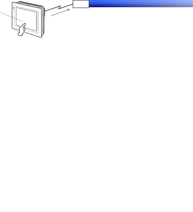
1-1-2 NS-series PT Operation
Displaying Screens
The data to be displayed on the screens (screen data) is created using the CX-Designer on a personal computer and the data is stored in the PT. The required screen can be displayed by a command from the host or by operating the touch switches.
Host
The required screens can be displayed by using commands from the host or touch switch operations.
Reading Data from the Host
NS-series PTs connect to the host using NT Links, Ethernet (for NS15-TX01@-V2, NS12-TS01(B)-V1/ -V2, NS10-TV01(B)-V1/-V2, NS8-TV@1(B)-V1/-V2, NS5-SQ@1(B)-V1, NS5-SQ@1(B)-V2, NS5-TQ@1(B)-V2, or NS5-MQ@1(B)-V2), or Controller Link (when Controller Link Interface Unit is installed) communications to automatically read required data from the host.
Host
NT Links, Ethernet, Controller Link
Sending Data to the Host
Data entered on the touch panel, (button ON/OFF status, numerals, and character strings) can be sent to the host.
Host
Touch panel
ON/OFF information, numeric data, etc.
1-2

Section 1 Overview |
1-1 NS-series PT Operation |
NS Series Programming Manual
Screen Data
The screen data displayed on PTs is created using CX-Designer on a personal computer. Screen data is transferred to the PT by connecting the PT and the personal computer using an RS-232C cable, a USB cable, or Ethernet (NS15-TX01@-V2, NS12-TS01(B)-V1/-V2, NS10-TV01(B)-V1/-V2, NS8-TV@1(B)-V1/-V2, NS5-SQ01(B)-V1, NS5-SQ@1(B)-V2, NS5-TQ@1(B)-V2, or S5-MQ@1(B)-V2).
RS-232C, USB, Create screen data.
Ethernet |
Computer |
|
(CX-Designer) |
Screen data |
|
Connect the computer to the PT only when transferring screen data to or from the CXDesigner.
Screen data can also be transferred using Memory Cards.
Memory Card
Computer (CX-Designer)
1-3

Section 1 Overview |
1-2 NS-series PT Functions |
NS Series Programming Manual
1-2 NS-series PT Functions
This section describes the features and main functions of the NS-series PTs.
1-2-1 NS-series PT Functions
Slim Body
1.Greater sophistication and reduced body thickness (panel depth 40 mm max.). (See note.)
2.Communications cable connectors housed inside Unit to eliminate protruding connectors.
Note: When mounted to a panel of the recommended thickness (1.6 to 4.8 mm).
Structure Suitable for FA Environments
1.Uses backlight with twice the life of previous OMRON PTs. (Return the PT to your nearest OMRON service center for replacement (at user expense).
2.IP65F (see note) or NEMA4 equivalent watertight construction.
Note: May not be applicable in environments with long-term exposure to oil.
Two standard-feature Ports for Serial Communications, Ports A and B, Enabling Connection to Both CX-Designer and the Host
1.Communications with the host via the other port are possible while still connected to CX-Designer.
2.Bar code data can be read from a bar code reader via the other port while communicating with the host.
Ethernet Interface
Ethernet communications with the host are possible for the NS15-TX01@-V2, NS12-TS01(B)-V1/-V2, NS10-TV01(B)-V1/-V2, NS8-TV@1(B)-V1/-V2, NS5-SQ01(B)-V1, NS5-SQ@1(B)-V2, NS5-TQ@1(B)-V2, or NS5-MQ@1(B)-V2.
Ethernet/IP communications with the host are also possible with for the NS15-TX01@-V2, NS12-TS01(B)-V2, NS10-TV01(B)-V2, NS8-TV01(B)-V2, NS5-SQ11(B)-V2, NS5-TQ11(B)-V2, and NS5-MQ11(B)-V2.
The CPU Units available with tag message communications through Ethernet/IP and the corresponding project versions are as follows:
Version 8.0 or higher: CJ2H-CPU@@-EIP, CJ2M-CPU3@ Version 8.5 or higher: NJ501-@@@@
Version 8.6 or higher: NJ101-@@@@, NJ301-@@@@
Version 8.9 or higher: NX701-@@@@
Version 8.93 or higher: NX1P2-@@@@
Version 8.96 or higher: NX102-@@@@
Controller Link Interface Unit
Installing a Controller Link Interface Unit enables using a Controller Link Network to send and receive large data packets flexibly and easily among OMRON PLCs and IBM PC/AT or compatible computers.
Note: The Controller Link Interface Unit is supported by the NS15, NS12, and NS10 only.
Display Video Images with a Video Input Unit
Installing a Video Input Unit enables displaying images from a video camera or Vision Sensor.
1-4

Section 1 Overview |
1-2 NS-series PT Functions |
NS Series Programming Manual
High Resolution and Large Display for a Wider Range of Display Possibilities
Display possibilities have been greatly increased with a larger display and higher resolution.
The NS15-TX01@-V2 uses an 1024-dot horizontal × 768-dot vertical, 256-color, 15.0-inch, bright TFT LCD.
The NS12-TS0@-V1/-V2 uses an 800-dot horizontal × 600-dot vertical, 256-color, 12.1-inch, bright TFT LCD.
The NS10-TV0@-V1/-V2 uses a 640-dot horizontal × 480-dot vertical, 256-color, 10.4-inch, bright TFT LCD.
The NS8-TV@@-V1 uses a 640-dot horizontal × 480-dot vertical, 256-color, 8.0-inch bright TFT LCD. The NS8-TV0@-V2 uses a 640-dot horizontal × 480-dot vertical, 256-color, 8.4-inch bright TFT LCD. The NS5-SQ0@-V1/V2 uses a 320-dot horizontal × 240-dot vertical, 256-color, 5.7-inch STN LCD.
The NS5-SQ1@-V2 uses a 320-dot horizontal × 240-dot vertical, 256-color, 5.7-inch bright TFT LCD. (Lot number 2110 or earlier: STN LCD.)
The NS5-TQ@@-V2 uses a 320-dot horizontal × 240-dot vertical, 256-color, 5.7-inch bright TFT LCD.
The NS5-MQ@@-V2 uses a 320-dot horizontal × 240-dot vertical, 16-grayscale monochrome, 5.7-inch bright STN LCD.
For BMP or JPEG images, 32,000-color displays (4,096 colors for the NS5-SQ0@, 16 grayscales for the NS5-MQ) are supported.
NS5-SQ1@-V2
NS5-TQ1@-V2
NS5-MQ1@-V2
More Precise Touch Switches
The NS12-TS0@-V1, NS10-TV0@-V1, NS5-SQ0@-V1, and NS5-SQ/TQ/MQ-V2 touch switches have 16-dot × 16-dot per element resolution and the NS8-TV@@-V1 touch switches have 20-dot × 20-dot per element resolution.
The NS15-TX01@-V2 uses an analog touch panel.
Fast System Program and Screen Data Replacement Using Memory Cards
1. Screen data can be written on site simply by mounting an HMC-EF*** Memory Card on the PT.
1-5

Section 1 Overview |
1-2 NS-series PT Functions |
NS Series Programming Manual
2.System programs can also be stored on Memory Cards with NS-series PTs.
3.Operation log data that contains alarm history data, data log data, error log data, functional object operations, screen display history, and macro execution history can be stored on Memory Cards. Data is saved in CSV files, which are easy to use on a personal computer.
Screen Data Confirmation Function
Screens can be checked even if CX-Designer is not connected, by using the System Menu on the PT.
Large Increase in Object Capacity
The number of objects that can be registered to screens has been increased dramatically. This allows screens with better display to be created. Refer to Display Specifications in Appendix 1 Specifications for details.
Character Display in Windows Fonts
Fonts used in Windows can be used in fixed (text) displays.
Simple Upgrades
The system program can be replaced using a Memory Card.
Conforms to International Standards
The PT conforms to UL standards, CSA standards, and EC Directives.
Multiple Windows
Up to 3 pop-up windows can be displayed at the same time on a normal screen. Commands to switch screens can also be given from the host.
Strong Processing Functions Using Macros
1.Various instructions are available, including arithmetic operations, bit operations, logic operations, comparison operations, screen controls (open, close, etc.), and object movement.
2.Processing can be performed independently from the host or data from the host can be further processed and the results can be displayed on the screen.
3.Host data processing can be transferred to macros to reduce the load on the host.
Multiple Label Registration
1.Up to 16 different languages or labels for production lines can be registered on one screen in the NS-series PTs.
2.The displayed label can be switched during operation.
More than 1,000 Standard Parts
NS-series PTs provide not only touch switches and lamps, but also complicated parts such as toggle switches and 7-segment displays. It is easy to create attractive screens simply by pasting on the CX-Designer.
1-6
Section 1 Overview |
1-2 NS-series PT Functions |
NS Series Programming Manual
1-2-2 Differences between Models
The NS15, NS12, NS10, NS8, and NS5 have different screen sizes.
Also, some models support only serial communications while others also support communications via the Ethernet.
Model |
Color |
Display panel |
Ethernet |
NS15-TX01S-V2 |
Silver |
15.0-inch bright TFT |
10/100Base-T |
NS15-TX01B-V2 |
Black |
15.0-inch bright TFT |
10/100Base-T |
NS12-TS00-V1 |
Ivory |
12.1-inch bright TFT |
Not available |
NS12-TS00B-V1 |
Black |
12.1-inch bright TFT |
Not available |
NS12-TS01-V1 |
Ivory |
12.1-inch bright TFT |
10/100Base-T |
NS12-TS01B-V1 |
Black |
12.1-inch bright TFT |
10/100Base-T |
NS10-TV00-V1 |
Ivory |
10.4-inch bright TFT |
Not available |
NS10-TV00B-V1 |
Black |
10.4-inch bright TFT |
Not available |
NS10-TV01-V1 |
Ivory |
10.4-inch bright TFT |
10/100Base-T |
NS10-TV01B-V1 |
Black |
10.4-inch bright TFT |
10/100Base-T |
NS8-TV@0-V1 |
Ivory |
8.0-inch bright TFT |
Not available |
NS8-TV@0B-V1 |
Black |
8.0-inch bright TFT |
Not available |
NS8-TV@1-V1 |
Ivory |
8.0-inch bright TFT |
10/100Base-T |
NS8-TV@1B-V1 |
Black |
8.0-inch bright TFT |
10/100Base-T |
|
|
|
|
NS12-TS00-V2 |
Ivory |
12.1-inch bright TFT |
Not available |
NS12-TS00B-V2 |
Black |
12.1-inch bright TFT |
Not available |
NS12-TS01-V2 |
Ivory |
12.1-inch bright TFT |
10/100Base-T |
NS12-TS01B-V2 |
Black |
12.1-inch bright TFT |
10/100Base-T |
NS10-TV00-V2 |
Ivory |
10.4-inch bright TFT |
Not available |
NS10-TV00B-V2 |
Black |
10.4-inch bright TFT |
Not available |
NS10-TV01-V2 |
Ivory |
10.4-inch bright TFT |
10/100Base-T |
NS10-TV01B-V2 |
Black |
10.4-inch bright TFT |
10/100Base-T |
NS8-TV00-V2 |
Ivory |
8.4-inch bright TFT |
Not available |
NS8-TV00B-V2 |
Black |
8.4-inch bright TFT |
Not available |
NS8-TV01-V2 |
Ivory |
8.4-inch bright TFT |
10/100Base-T |
NS8-TV01B-V2 |
Black |
8.4-inch bright TFT |
10/100Base-T |
NS5-SQ00-V1 |
Ivory |
5.7-inch STN |
Not available |
NS5-SQ00B-V1 |
Black |
5.7-inch STN |
Not available |
NS5-SQ01-V1 |
Ivory |
5.7-inch STN |
10/100Base-T |
NS5-SQ01B-V1 |
Black |
5.7-inch STN |
10/100Base-T |
NS5-SQ00-V2 |
Ivory |
5.7-inch STN |
Not available |
NS5-SQ00B-V2 |
Black |
5.7-inch STN |
Not available |
NS5-SQ01-V2 |
Ivory |
5.7-inch STN |
10/100Base-T |
NS5-SQ01B-V2 |
Black |
5.7-inch STN |
10/100Base-T |
NS5-SQ10-V2 |
Ivory |
5.7-inch TFT |
Not available |
(See note.) |
|
|
|
NS5-SQ10B-V2 |
Black |
5.7-inch TFT |
Not available |
(See note.) |
|
|
|
NS5-SQ11-V2 |
Ivory |
5.7-inch TFT |
10/100Base-T |
(See note.) |
|
|
|
NS5-SQ11B-V2 |
Black |
5.7-inch TFT |
10/100Base-T |
(See note.) |
|
|
|
NS5-TQ00-V2 |
Ivory |
5.7-inch bright TFT |
Not available |
NS5-TQ00B-V2 |
Black |
5.7-inch bright TFT |
Not available |
NS5-TQ01-V2 |
Ivory |
5.7-inch bright TFT |
10/100Base-T |
NS5-TQ01B-V2 |
Black |
5.7-inch bright TFT |
10/100Base-T |
1-7

Section 1 Overview |
|
|
1-2 NS-series PT Functions |
||
NS Series Programming Manual |
|
|
|
||
|
|
|
|
|
|
|
Model |
Color |
Display panel |
Ethernet |
|
|
NS5-TQ10-V2 |
Ivory |
5.7-inch bright TFT |
Not available |
|
|
NS5-TQ10B-V2 |
Black |
5.7-inch bright TFT |
Not available |
|
|
NS5-TQ11-V2 |
Ivory |
5.7-inch bright TFT |
10/100Base-T |
|
|
NS5-TQ11B-V2 |
Black |
5.7-inch bright TFT |
10/100Base-T |
|
|
NS5-MQ00-V2 |
Ivory |
5.7-inch monochrome STN |
Not available |
|
|
NS5-MQ00B-V2 |
Black |
5.7-inch monochrome STN |
Not available |
|
|
NS5-MQ01-V2 |
Ivory |
5.7-inch monochrome STN |
10/100Base-T |
|
|
NS5-MQ01B-V2 |
Black |
5.7-inch monochrome STN |
10/100Base-T |
|
|
NS5-MQ10-V2 |
Ivory |
5.7-inch monochrome STN |
Not available |
|
|
NS5-MQ10B-V2 |
Black |
5.7-inch monochrome STN |
Not available |
|
|
NS5-MQ11-V2 |
Ivory |
5.7-inch monochrome STN |
10/100Base-T |
|
|
NS5-MQ11B-V2 |
Black |
5.7-inch monochrome STN |
10/100Base-T |
|
Note: The specifications of NS5-SQ1@-V2 PTs with lot number 2110 (manufactured January 21, 2010)or earlier are given below.
Item |
Specification |
Display panel |
Color STN LCD |
Display colors |
256 colors (4,096 colors for BMP/JPEG images) |
View angle |
Left: 50°, Right: 50°, Top: 45°, Bottom: 50° |
1-8

Section 1 Overview |
1-2 NS-series PT Functions |
NS Series Programming Manual
1-2-3 Main NS-series Functions
The NS-series PTs have the following main functions.
Display Functions |
|
||
Screen Displays |
|
||
|
|
|
|
Large, high - resolution screen with many graphic functions. |
|
||
1024 x 768 - dot (horizontal x vertical), 256 - color, 15.0-in, bright TFT LCD |
|
||
NS15-TX01@-V2 |
|
||
800 x 600 - dot (horizontal x vertical), 256 - color, 12.1-in, bright TFT LCD |
|
||
NS10-TV0@-V1/-V2 |
|
||
640 x 480 - dot (horizontal x vertical), 256 - color, 10.4-in, bright TFT LCD |
|
||
NS8-TV@@-V1 |
|
||
640 x 480 - dot (horizontal x vertical), 256 - color, 8.0-in, bright TFT LCD |
|
||
NS8-TV0@-V2 |
|
||
640 x 480 - dot (horizontal x vertical), 256 - color, 8.4-in, bright TFT LCD |
|
||
NS5-SQ0@-V1/-V2 |
|
||
32 0 x 24 0 - dot (horizontal x vertical), 256 - color, 5.7-in, STN LCD |
|
||
NS5-SQ1@-V2 (See note.) |
|
||
320 x 240 - dot (horizontal x vertical), 256 - color, 5.7-in, TFT LCD |
RUN |
||
NS5-TQ@@-V2 |
|
||
32 0 x 24 0 - dot (horizontal x vertical), 256 - color, 5.7-in, bright TFT LCD |
|
||
NS5-MQ@@-V2 |
|
||
320 x 240 - dot (horizontal x vertical), 5.7-in, 16-grayscale monochrome |
|
||
STN LCD |
|
||
Characters |
|
||
Display characters at various sizes. Characters can be flashed or |
|
||
character colors can be changed. |
|
||
Fixed Objects |
|
||
Lines, poly lines, rectangles, polygons, circles, oval, arcs, and sectors |
|
||
can be displayed. Objects can be filled in various colors and flashed. |
|
||
Internal Memory Data |
|
||
The contents of registers in internal memory ($B, $W, $HB, $HW, $SB, |
|
||
and $SW) can be displayed. |
|
||
Graphs |
|
||
Bar graphs, analog meters, broken - line graphs, and trend (data |
|
||
logging) graphs are supported. |
|
||
Lamps |
|
||
Lamps controlled by the host can be lit or flashed. Different graphics |
|
||
can be used for lit and not lit status. |
|
||
Alarms/Events |
|
||
Host bit status can be used to automatically display messages and |
|
||
related information (e.g., time stamps). |
|
||
Alarms and events can be displayed one line at a time, in lists, |
|
||
or in histories. |
|
||
Note: Lot number 2110 or earlier use an STN LCD.
Communications Functions: Host Communications
Any of five communications methods can be used: 1:1 NT Links, 1:N NT
Links (standard or high speed), Ethernet, Ethernet/IP (Ethernet: NS15-TX01@-V2, NS12-TS01(B)- V1/-V2, NS10- TV01(B)-V1/-V2, NS8-TV@1(B)-V1/-V2, NS5- SQ01(B)-V1,
NS5-SQ@1(B)-V2, NS5-TQ@1-V2, and NS5-MQ@1-V2), or Controller Link. Host data can be read and displayed, and data can be input and sent to the host, for buttons, numeral display and input objects, and character display and input objects.
Output Functions: Buzzer
The buzzer in the PT can be controlled
1-9

Section 1 Overview |
1-2 NS-series PT Functions |
NS Series Programming Manual
Input Functions
Inputting via Touch Switches
Buttons can be displayed easy input by touching the screen. Input functions include sending data to the host and
switching the display screen.
Popup Windows
Windows that overlap the current screen can be opened, closed, and moved. Various objects can be registered for pop-up windows, and up to three popup windows can be displayed at the same time. Accessing the required
windows when needed enables more effective use of screens.
Numeral/Character String Input
Touch switches can be used to input numerals and character strings. The input data can be sent to the host, and inputs can also be prohibited using controls from the host.
Bar Code Reader Inputs
Data read from bar code readers can be input to character string display and input objects.
Control Flags
Allocating host addresses to control bits enables controlling display of functional objects and enabling or disabling input functions from the host.
System Functions
System Menu
System setting and maintenance are performed from the system menu displayed on the screen.
Creating Screen Data
The CX-Designer running on a personal computer is used to create screen data and record it in memory built into the PT. Screen data can also be saved on Memory Cards in the PT.
Screen Saver
A screen saver increases the life of the backlight.
Built-in Clock
The builtin clock enables displaying dates and times.
Device Monitor Function
When connected to a PLC via a 1:1 NT Link, 1:N NT Link, or Ethernet, the PLC’s operating mode can be changed, words in the PLC can be read or written, error information can be written, etc.
Data Transfers
Screen data and system programs can be transferred by the Transfer Data function on the CX-Designer or by using Memory Cards. Data can also be transferred to the PT through a PLC and ladder program data, for example, can be
transferred through a PT to a PLC.
Operation Logging and Alarm/Event History
A history can be kept of screen switches, functional object operation, and macro execution. The times and frequency
that specific addresses turn ON can also be kept in a history.
Data Logging for Trend Graphs and Background Execution
The contents of addresses displayed for trend graphs can be logged, even while the graph is not being displayed (background execution).
Macros
Calculations data can be set as screen data to perform calculations at specific times during PT operation.
Calculations include arithmetic, bit operations, logic operations, and comparisons. Various commands are also provided, e.g., to move objects or pop-up windows, manipulate character strings, etc.
Starting External Applications
Ladder monitor or other applications can be started from the system menu.
Printing
Screens can be printed out on a printer connected with an USB cable NS15, NS12, NS10, NS8, or NS5-@@1@-V2 only.
Programming Console Function
The PT can perform Programming Console functions by placing a Memory Card containing a program into the PT.
NS Switch Box
The comments of a specified PLC address can be displayed and data at the address can be monitored or changed.
1-10
Section 1 Overview |
1-2 NS-series PT Functions |
NS Series Programming Manual
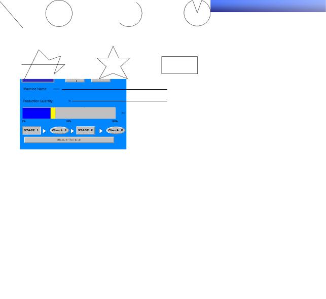
1-2-4 NS-series Displays
A variety of elements can be displayed on one screen, including character strings, numerals, graphs, lamps, and buttons. The screen data displayed on NS-series PTs is created using CX-Designer.
Characters (text)
 ON/OFF buttons
Characters (string display and input)
Numerals (numeral display and input)
 Graphs (level meter)
 Lamps (bit lamps)
 Fixed objects
 Alarm objects (Alarm/event display)
Fixed Objects
A fixed object is merely graphic data displayed on the screen. Unlike functional objects, fixed objects cannot exchange data with the host, execute operations, or change display attributes (except for flickering). There are seven types of fixed objects: Lines, circles/ovals, arcs, sectors, polylines, polygons, and rectangles.
Line |
Circle or Oval |
Arc |
Sector |
Polyline |
|
Polygon |
|
Rectangle |
Buttons
Button can be registered to the screens as required. There are three types of buttons: ON/OFF buttons, word buttons, and command buttons. The following functions can be executed by touching the buttons on the screen.
•Turn bits ON or OFF (ON/OFF buttons).
•Write numerals to words (word buttons).
•Switch the displayed screen (command buttons).
•Transfer numeral or character string data (command buttons).
•Open, close, or move pop-up screens (command buttons).
•Display the System Menu (command buttons).
•Stop the buzzer (command buttons).
Buttons can be lit depending on the status of the allocated address.
Also, inputs from the host can be controlled (enabled or disabled) by allocating the address of a control flag.
There are three display shapes for buttons: Rectangle, select shape (ON/OFF buttons and word buttons), and circle (for ON/OFF buttons only). When the select shape option is used, the display shape is specified for the ON and OFF status of the allocated address.
There are two types of button labels: Fixed string display and ON/OFF switch display (for ON/OFF buttons only). In addition, the label can be displayed on multiple lines.
1-11

Section 1 Overview |
1-2 NS-series PT Functions |
NS Series Programming Manual
Lamps
There are two types of functional objects, bit lamps and word lamps, that change the display status depending on the status of the allocated address.
The color and shape of the lamps can be changed depending on the ON/OFF status of bits for bit lamps or the contents of words for word lamps.
Allocated address |
Allocated address |
0, 1, 0, 1…… |
0, 1, 2, 3, 4, 5…… |
OFF, ON, OFF, ON…… |
Color 1, Color 2, Color 3, Color 4…… |
Bit lamp |
Word lamp |
Fixed character strings can be displayed as lamp labels. In addition, multiple lines can be displayed.
Numeral Display and Input
Numerals stored at the allocated address can be displayed and data can be input to the allocated address. Four different data formats can be displayed as required, including decimal and hexadecimal, and data can be stored as required in any of eleven data formats, including signed integers and BCD. Host values can be converted and displayed at a specified scale or displayed with units, such as mm or g.
Also, inputs from the host can be controlled (enabled or disabled) by assigning the address of a control flag.
Allocated address
12345
Keypad input
12345
1-12
Section 1 Overview |
1-2 NS-series PT Functions |
NS Series Programming Manual
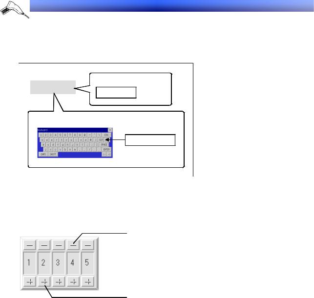
String Display and Input
Character string data stored at allocated addresses can be displayed and can be input to the address. Bar code data can be read using a bar code reader.
Also, inputs from the host can be controlled (enabled or disabled) by allocating the address of a control flag.
Barcode input
Character string
Character string
Virtual keyboard input
Character string
Thumbwheel Switches
The numerical contents of the allocated address can be input by incrementing or decrementing the numeral using the + and – buttons for each digit.
Also, inputs from the host can be controlled (enabled or disabled) by allocating the address of a control flag.
Decrement
Increment
1-13
Section 1 Overview |
1-2 NS-series PT Functions |
NS Series Programming Manual
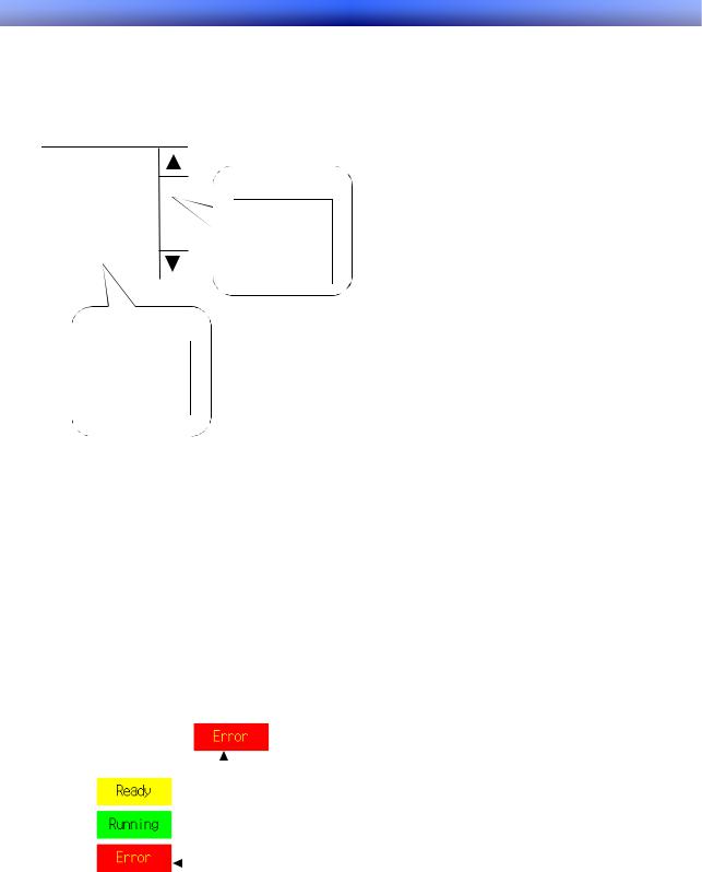
List Selections
Allocated addresses or character string data stored in text files can be displayed in a list and specific character strings can be specified from the list.
Also, inputs from the host can be controlled (enabled or disabled) by allocating the allocated address of a control flag.
Item 1 |
|
|
|
|
Item 2 |
|
|
Allocated address |
|
Item 3 |
|
|
|
|
|
|
Item 1 |
|
|
Item 4 |
|
|
|
|
Item 5 |
|
|
Item 2 |
|
Item 6 |
|
|
Item 3 |
|
Item 7 |
|
|
Item 4 |
|
|
|
|
|
|
|
|
|
|
|
|
|
|
|
|
Text files
Item 1
Item 2
Item 3
Item 4
Text
Preset character strings can be displayed.
Display characters can also be changed.
The following three methods are available for changing displayed characters.
•Indirect Specification From a Text File
A list of character strings to be displayed can be stored in a text file and any character string in the text file can be specified for display.
•Indirect Specification From a Character String Table
Any character string can be specified for display from preset character strings in a character string table.
•Message Indicator Function
Character strings and background colors to be displayed can be registered for each status number
and any registered status can be specified for display.
Text object
|
|
|
|
|
Displays status 3. |
|
|
|
|
||||
Status 1 |
|
|
|
|||
Status 2 |
|
Status switching |
|
|||
|
|
|
|
|
|
|
|
|
|
|
|
addresses |
|
Status 3 |
|
|
|
|
Specifies status 3. |
|
|
|
|
|
HOST1: 00001=2 |
||
|
|
|
|
|
||
|
|
|
|
|
|
|
Bitmaps
Bitmaps are functional objects that display bitmap files or JPEG files. Complex pictures or photographic images that cannot be drawn can be displayed on the screen. The display can also switch among different images depending on the contents of the specified address.
Level Meters
The current value of the allocated address can be displayed by coloring the specified range. The display
1-14

Section 1 Overview |
1-2 NS-series PT Functions |
NS Series Programming Manual
direction (up, down, left, or right), different color for each specified range, and whether or not scaling will be used can be set.
100
50
20
0
Allocated address |
Allocated address |
Allocated address |
contains 20. |
contains 50. |
contains 100. |
Analog Meters
An analog meter displays the current value for the allocated address by coloring regions or by means of a needle. The shape can be selected from a quarter circle, semi-circle, and full circle.
The display direction (up, down, left, or right), incremental direction for the meter (clockwise or an- ti-clockwise), and whether or not scaling will be used can be set.
Broken-line Graphs
Broken-line graphs display the present values for multiple consecutive allocated addresses on one graph.
Up to 256 line graphs can be displayed in one broken-line graph display region.
Data Log Graphs
The data log function saves changes over time in the contents of the allocated address. The saved data can be displayed for each data logging group.
Data can be read (sampled) even if the data log graph is not displayed.
1-15

Section 1 Overview |
1-2 NS-series PT Functions |
NS Series Programming Manual
Alarms and Events
The alarm/event function reports alarms based on changes in bit status. There are two functional objects: Alarm/event displays and alarm/event summary and history.
Alarm/event display objects display a pre-registered message and the date and time of the alarm or event when the monitored bit turns ON.
Either one message or multiple messages (using the flowing string function) can be displayed.
The alarm/event summary and history functional object displays a list of messages. The display order can be switched between displaying in order of occurrence, order of frequency, and by alarm level. Also, the history and data to be displayed when an alarm is generated can be selected.
System Clock
The system clock displays the current date and time. The date and time can also be changed.
Data Blocks
Data blocks (recipes) enable reading/writing values and character strings from/to memory areas, such as those in a PLC. Data blocks can be used to easily change the setup of the system. Create the data in a CSV file and store it in the PT beforehand. This data can be changed while operating the PT.
Example: Setting width (numeric value), height (numeric value), and color (character string) in the PLC. (Refer to the figure shown below.)
Set width: 150, height: 54, and color: blue for product B. Just select product B to set these three items in the PLC. If product A is selected a width for 100, a height of 52, and a color of red are set in the PLC.
Product B processing conditions
To machines
Data Block |
|
|
|
|
Width |
Height |
Color |
Product A |
100 |
52 |
Red |
Product B |
150 |
54 |
Blue |
Product C |
200 |
56 |
Yellow |
Product D |
|
|
Product B |
300 |
62 |
Red |
|
Product E |
Product B selected to set |
Blue |
|
|
|
||
1-16
Loading...