


Smart Sensor
Vision Sensor with built-in LCD monitor
ZFX-C20
Serial Communication
Command Reference
Cat. No. Z265-E1-01

Introduction
Thank you for purchasing the ZFX-C.
This manual provides information regarding functions, performance and operating methods that are required for using the ZFX-C.
When using the ZFX-C, be sure to observe the following:
•The ZFX-C must be operated by personnel knowledgeable in electrical engineering.
•To ensure correct use, please read this manual thoroughly to deepen your understanding of the product.
•Please keep this manual in a safe place so that it can be referred to whenever necessary.
Manuals Provided with this Product
Smart Sensor
Vision Sensor with built-in LCD monitor
ZFX-C20
User's Manual
Cat. No. Z264-E1-01
Smart Sensor
Vision Sensor with built-in LCD monitor
ZFX-C20
Serial Communication
Command Reference
User's Manual
This manual describes basic operations, such as installation and connections, and information on settings and specifications to ensure safe and correct use of this product.
Serial Communication Command Reference (this document)
This manual provides reference information for when this product performs communications with an external device, such as a PC or a programmable controller, via the serial interface.
Cat. No. Z265-E1-01

Contents
Communication Interface Specifications . . . . . . . . . . . . . . . . . . . . . . . . . . 2
Connection. . . . . . . . . . . . . . . . . . . . . . . . . . . . . . . . . . . . . . . . . . . . . . . . . . . 3
Connecting a PC . . . . . . . . . . . . . . . . . . . . . . . . . . . . . . . . . . . . . . . . . . . . . . . . . . . 3
Connecting a PLC . . . . . . . . . . . . . . . . . . . . . . . . . . . . . . . . . . . . . . . . . . . . . . . . . . 5
About Communication Commands . . . . . . . . . . . . . . . . . . . . . . . . . . . . . . . 6
Command/Response Format. . . . . . . . . . . . . . . . . . . . . . . . . . . . . . . . . . . . . . . . . . 6
Available Commands . . . . . . . . . . . . . . . . . . . . . . . . . . . . . . . . . . . . . . . . . . . . . . . . 9
Bank Control Commands. . . . . . . . . . . . . . . . . . . . . . . . . . . . . . . . . . . . . . . . . . . . 11
Measurement Control/Measurement Value Acquisition Commands . . . . . . . . . . . 13
Setting Acquisition/Change Commands . . . . . . . . . . . . . . . . . . . . . . . . . . . . . . . . 16
Backup/Restore Commands . . . . . . . . . . . . . . . . . . . . . . . . . . . . . . . . . . . . . . . . . 20
Utility Commands. . . . . . . . . . . . . . . . . . . . . . . . . . . . . . . . . . . . . . . . . . . . . . . . . . 30
Parameter List . . . . . . . . . . . . . . . . . . . . . . . . . . . . . . . . . . . . . . . . . . . . . . . . . . . . 31
Example of Usage . . . . . . . . . . . . . . . . . . . . . . . . . . . . . . . . . . . . . . . . . . . . 37
Version Upgrade Information. . . . . . . . . . . . . . . . . . . . . . . . . . . . . . . . . . . 41
Revision History . . . . . . . . . . . . . . . . . . . . . . . . . . . . . . . . . . . . . . . . . . . . . 44
|
1 |
|
ZFX-C Serial Communication Command Reference |
||
|

Communication Interface Specifications
You can use the USB port or RS-232C/422 connector of the Controller to perform serial communication with external devices such as a personal computer or programmable controller.
Serial communication functions in the RUN mode. Communication cannot be performed in the ADJ or MENU modes.
<USB>
This interface allows Full speed (12 Mbps) communications compliant with USB2.0 with a PC equipped with the same USB interface.
Synchronization method Start-stop
Transmission code |
ASCII (Binary format can be selected only when outputting measurement values set at |
|
[Setup] - [Support] - [Calculation] - [Data].) |
|
|
Communication speed |
USB2.0-compliant |
|
|
Data length |
- |
|
|
Parity |
- |
|
|
Stop bit |
- |
|
|
Delimiter |
CR, LF, CR+LF |
|
|
Transmission protocol |
Normal (Note, however, that XMODEM protocol is used when sending image data, system |
|
data and other data.) |
<RS-232C/422>
This interface allows data communications compliant with the EIA RS-232C/422 standards up to a maximum speed of 115200 bps.
Synchronization method Start-stop
Transmission code |
ASCII (Binary format can be selected only when outputting measurement values set at |
|
[Setup] - [Support] - [Calculation] - [Data].) |
|
|
Communication speed |
9600, 19200, 38400, 57600, 115200 |
|
|
Data length |
7 bits, 8 bits |
|
|
Parity |
None, even, odd |
|
|
Stop bit |
1 bit, 2 bits |
|
|
Delimiter |
CR, LF, CR+LF |
|
|
Transmission protocol |
Normal (Note, however, that XMODEM protocol is used when sending image data, system |
|
data and other data.) |
For details on how to set the communication specifications, refer to the User's Manual.
<Ethernet>
Communication protocol TCP/IP
Transmission mode |
Peer to Peer |
2 |
Communication Interface Specifications |
ZFX-C Serial Communication Command Reference |
|

Connection
Connecting a PC
<USB>
Use a USB cable (ZFX-XUSB) to connect the Controller to the
PC.
Important
• When connecting the PC, refer to the Instruction Manual for the PC.
• Attach the ferrite cores supplied to both ends of the USB cable.
Ferrite cores
Note
Installation of the USB driver is necessary only when connecting an external device to the USB interface for the first time.
For the USB driver, please contact your OMRON representative.
<Ethernet>
Use a commercially available LAN cable to connect the Controller to the PC.
There are two ways of making the LAN connection to the PC, directly to the PC or via a hub.
Important
The following communications are not possible:
•Communications with the Controller from outside the LAN
•Communications between the Controller and two or more PCs
•Communications between Controllers
•Communications between the Controller and the PLC
|
|
3 |
|
ZFX-C Serial Communication Command Reference |
Connection |
||
|

• 1:1 Connection
When connecting the Controller directory to the PC, use a 10BASE-T or 100BASE-TX cross cable (Category 5 or higher). Limit the cable length to 30 m.
Example: A measurement command is input and the result is acquired.
If communications software for a TELNET connection is activated on the PC to access the Controller, the Controller will automatically switch to the Ethernet connection.
Input command.
Execute
measurement. MEASURE
The parallel interface's ENABLE signal will be OFF during measurement.
Output the processing result.
Receive the |
To end the Ethernet connection, input the |
measurement result. |
EXIT command. |
• 1:N Connection
When connecting two or more Controllers to one PC via a hub, use a 10BASE-T or 100BASE-TX straight cable (Category 5 or higher). Also, limit the cable lengths between the PC and the hub, and the Controllers and the hub to 30 m, respectively. Be sure to set unique IP addresses to each Controller. Do not set duplicate IP addresses to Controllers.
Example:
IP address 192.168.250.010
Start the TELNET communications software on the PC, and specify individual IP addresses to access each Controller. The method for inputting commands is the same as for a 1:1 connection.
HUB
IP address |
IP address |
IP address |
192.168.250.100 |
192.168.250.101 |
192.168.250.102 |
4 |
Connection |
ZFX-C Serial Communication Command Reference |
|

Connecting a PLC
Use the exclusive RS-232C cable (ZFX-XPT2A) / RS-422 cable (ZFX-XPT2B) to connect the Controller to a PLC.
Important
When connecting to a PLC, refer to the Instruction Manual for the
PLC.
|
|
5 |
|
ZFX-C Serial Communication Command Reference |
Connection |
||
|
About Communication Commands
Command/Response Format
< Command >
Command data Delimiter
< Response >
When processing ends successfully
Response data |
Record |
separator |
Record
O K separator
When processing fails
E R Recordseparator
Command data |
Specifies the command and parameters in ASCII code. |
|
|
Response data |
Stores the acquired data. |
|
|
Delimiter |
This control code indicates the end of the data. |
|
|
Record separator |
This delimiter is appended to one session's worth of output data. (default delimiter: CR) |
|
|
6 |
About Communication Commands |
ZFX-C Serial Communication Command Reference |
|

Configuration of Measurement Value Data
The following explains the output format of measurement values.
To output measurement values by serial communication, the following items must be set.
Note
Output content
Set the output content as an expression.
Set the output content at [Setup] - [Support] - [Calculation] - [Data].
Output destination
Specify [RS-232C/422] or [USB] at [System] - [Output] - [Data output].
Output format
Set the output format at [System] - [Output] - [Serial output].
For detailed settings, refer to the User's Manual.
ASCII Format |
Up to 32 results are output as a data structure of fixed length of up to 12 characters including the sign.
|
Measurement value of data 0 |
|
|
Measurement value of data 1 |
Measurement value of data 31 |
|
|
|||||||||||||||||||||||||||||||||||||||||||||||||||
|
|
|
|
|
|
|
|
|
|
|
|
|
|
|
|
|
|
|
|
|
|
|
|
|
|
|
|
|
|
|
|
|
|
|
|
|
|
|
|
|
|
|
|
|
|
|
|
|
|
|
|
|
|
|
|
|
|
Record |
|
|
|
|
|
|
|
|
|
|
|
|
|
|
|
|
|
|
|
|
|
|
|
|
|
|
|
|
|
|
|
|
|
|
|
|
|
|
|
|
|
|
|
|
|
|
|
|
|
|
|
|
|
|
|
|
|
|
|
|
|
|
|
|
|
|
|
|
|
|
|
|
|
|
|
|
|
|
|
|
|
|
|
|
|
|
|
|
|
|
|
|
|
|
|
|
|
|
|
|
|
|
|
|
|
|
|
|
|
|
|
|
|
|
|
|
|
|
|
|
|
|
|
|
|
|
|
|
|
|
|
|
|
|
|
|
|
Field separator |
|
|
|
|
|
|
|
|
|
|
|
|
|
|
|
|
|
|
|
|
|
|
|
|
|
|
|
||||||||||||
|
|
|
|
|
|
|
|
|
|
|
|
|
|
|
|
|
|
|
|
|
|
|
|
|
|
|
|
|
|
|
|
|
|
|
|
|
|
|
|
|
|
|
|
|
|
|||||||||||||
|
|
|
|
|
|
|
|
|
|
|
|
|
|
|
|
|
|
|
|
|
|
|
|
|
|
|
|
|
|
|
|
|
|
|
|
|
|
|
|
|
|
|
|
|
|
|||||||||||||
|
|
|
|
|
|
|
|
|
|
|
|
|
|
|
|
|
|
|
|
|
|
|
|
|
|
|
|
|
|
|
|
|
|
|
|
|
|
|
|
|
|
|
|
|
||||||||||||||
|
|
|
|
|
|
|
|
|
|
|
|
|
|
|
|
|
|
|
Number of digits past the decimal point: max. 3 |
|
separator |
|||||||||||||||||||||||||||||||||||||
|
|
|
|
|
|
|
|
|
|
|
|
|
|
|
|
|
|
|
||||||||||||||||||||||||||||||||||||||||
|
|
|
|
|
|
|
|
|
|
|
|
|
|
|
|
|
|
|
Decimal separator: 1 digit |
|
|
|
|
|
|
|
|
|
|
|
|
|
|
|
|
|||||||||||||||||||||||
|
|
|
|
|
|
|
|
|
|
|
|
|
|
|
|
|
|
|
|
|
|
|
|
|
|
|
|
|
|
|
|
|
|
|
||||||||||||||||||||||||
|
|
|
|
|
|
|
|
|
|
|
|
|
|
|
|
|
|
|
Sign + number of digits of integer section: max. 8 digits |
|
|
|||||||||||||||||||||||||||||||||||||
|
|
|
|
|
|
|
|
|
|
|
|
|
|
|
|
|
|
|
(Insert "0" for spaces.) |
|
|
|
|
|
|
|
|
|
|
|
|
|
|
|
|
|||||||||||||||||||||||
|
|
|
|
|
|
|
|
|
|
|
|
|
|
|
|
|
|
|
|
|
|
|
|
|
|
|
|
|
|
|
|
|
|
|
|
|
|
|
|
|
|
|
|
|
|
|
|
|
|
|
|
|
|
|
|
|
|
|
|
Sign |
|
|
|
|
|
|
|
The sign of the measurement value is stored. Plus: 0/Minus: - |
|
|
|||||||||||||||||||||||||||||||||||||||||||||||
|
|
|
|
|
|
|
|
|
|
|
|
|
|
|
|
|
|
|
|
|
|
|
|
|
|
|
|
|
|
|
|
|
|
|
|
|
|
|
|
|
|
|
|
|
|
|
|
|
|
|
|
|
|
|
|
|
|
|
|
Number of digits of integer section |
|
|
|
|
"0" is inserted in spaces in the integer section and digits past the decimal |
||||||||||||||||||||||||||||||||||||||||||||||||||||
|
|
|
|
|
|
|
|
|
|
|
|
|
|
|
|
|
|
|
|
|
|
point. |
|
|
|
|
|
|
|
|
|
|
|
|
|
|
|
|
|
|
|
|
|
|
|
|
|
|
|
|
||||||||
|
Number of digits past the decimal point |
|
|
|
|
|
|
|
|
|
|
|
|
|
|
|
|
|
|
|
|
|
|
|
|
|
|
|
|
|||||||||||||||||||||||||||||
|
When a value is greater than the preset number of digits, all digits other |
|||||||||||||||||||||||||||||||||||||||||||||||||||||||||
|
Decimal separator |
|
|
|
|
|
|
|
than the sign digit become "9". |
|
|
|
|
|
|
|
|
|
|
|
|
|
|
|
|
|||||||||||||||||||||||||||||||||
|
|
|
|
|
|
|
|
|
|
|
|
|
|
|
|
|
|
|
|
|
|
Output range: -9999999.999 to 09999999.999 |
|
|
||||||||||||||||||||||||||||||||||
|
Field separator |
|
|
|
|
|
|
|
|
|
||||||||||||||||||||||||||||||||||||||||||||||||
|
|
|
|
|
|
|
|
|
|
|
|
|
|
|
|
|
|
|
|
|
|
|
|
|
|
|
|
|
|
|
|
|
|
|
|
|
|
|
|
|
|
|
|
|
||||||||||||||
|
|
|
|
|
|
|
|
|
|
|
|
|
|
|
|
|
|
|
|
|
|
|
|
|
|
|
|
|
|
|
|
|
|
|
|
|
|
|
|
|
|
|
|
|
|
|
|
|
|
|
|
|
|
|
|
|
|
|
|
Record separator |
|
|
|
|
|
|
|
|
|
|
|
|
|
|
|
|
|
|
|
|
|
|
|
|
|
|
|
|
|
|
|
|
|
|
|
|
|
|
|
|
|
|
|
|
|||||||||||||
|
|
|
|
|
|
|
|
|
|
|
|
|
|
|
|
|
|
|
|
|
|
|
|
|
|
|
|
|
|
|
|
|
|
|
|
|
|
|
|
|
|
|
|
|
|
|
|
|
|
|
|
|
|
|
|
|
|
|
|
Example: Number of digits of integer section: 7, number of digits past the decimal point: 3, |
|
|
|||||||||||||||||||||||||||||||||||||||||||||||||||||||
|
|
|
|
|
decimal separator: period |
|
|
|
|
|
|
|
|
|
|
|
|
|
|
|
|
|
|
|
|
|
|
|
|
|
|
|
|
|||||||||||||||||||||||||
|
|
|
< Measurement value > < Data structure > |
|
|
|
|
|
|
|
|
|
|
|
|
|
|
|
|
|
|
|
|
|
|
|
|
|
|
|
|
|||||||||||||||||||||||||||
|
|
|
|
|
|
|
|
|
|
|
|
|
|
|
|
|
|
|
|
|
|
|
|
|
|
|
|
|
|
|
|
|
|
|
|
|||||||||||||||||||||||
123456.789 |
|
|
|
|
|
|
|
0 |
1 |
2 |
3 |
4 |
5 |
6 |
. |
7 |
8 |
9 |
CR |
|
|
|
|
|
|
|
|
|
|
|
|
|
|
|
|
|
|
|
|
|||||||||||||||||||
|
|
|
|
|
|
|
|
|
|
|
|
|
|
|
|
|
|
|
|
|
|
|
|
|
|
|
|
|||||||||||||||||||||||||||||||
4567.8 |
|
|
|
|
|
|
|
|
|
0 |
0 |
0 |
4 |
5 |
6 |
7 |
. |
8 |
0 |
0 |
CR |
|
|
|
|
|
|
|
|
|
|
|
|
|
|
|
|
|
|
|
|
|||||||||||||||||
|
|
|
|
|
|
|
|
|
|
|
|
|
|
|
|
|
|
|
|
|
|
|
|
|
|
|
|
|||||||||||||||||||||||||||||||
-4567.8 |
|
|
|
|
|
|
|
|
|
- |
0 |
0 |
4 |
5 |
6 |
7 |
. |
8 |
0 |
0 |
CR |
|
|
|
|
|
|
|
|
|
|
|
|
|
|
|
|
|
|
|
|
|||||||||||||||||
|
|
7 |
|
ZFX-C Serial Communication Command Reference |
About Communication Commands |
||
|

Binary Format |
The value obtained by multiplying the measurement value by 1000 is output continuously as four bytes per single data item. Minus values are output as 2's complement. Up to 32 results can be output.
The binary format differs from the ASCII format in that data separators, such as field separator or record separator, do not exist.
Output range: -2147483.648 to 2147483.647
Measurement value |
Measurement value |
|
|
|
Measurement value |
|||||||||||
of data 0 x 1000 |
of data 1 x 1000 |
|
|
|
of data 31 x 1000 |
|||||||||||
|
|
|
|
|
|
|
|
|
|
|
|
|
|
|
|
|
|
|
|
|
|
|
|
|
|
|
|
|
|
|
|
|
|
|
|
|
|
|
|
|
|
|
|
|
|
|
|
|
|
|
|
|
|
|
|
|
|
|
|
|
|
|
|
|
|||
|
|
|
|
|
|
|
|
|
|
|
|
|
|
|
|
|
|
|
|
|
|
|
|
|
|
|
|
|
|
|
|||
|
4 bytes |
|
4 bytes |
|
|
|
|
|
4 bytes |
|||||||
Example: Data 0 "256.324" and data 1 "-1.000"
$00 $03 $E9 $44 $FF $FF $FC $18
|
|
Data 0: 256324 |
Data 1: -1000 |
(256.324 x 1000) |
(-1.000 x 1000) |
Note
•A value obtained by multiplying by 1000 also is output as the judgment result (JG). OK: 0
NG: -1000 (-1 x 1000)
•When the measurement value is less than -2147483.648, "-2147483.648" is output. When the measurement value is greater than 2147483.647, "2147483.647" is output.
8 |
About Communication Commands |
ZFX-C Serial Communication Command Reference |
|
Available Commands
Bank Control Commands
Command name |
Description |
Page |
|
|
|
BANK (or BK) |
This command acquires the current bank No. |
p.11 |
|
|
|
|
This command switches the bank to be used. |
p.11 |
|
|
|
BANKGROUP (or BG) |
This command acquires the current bank group No. |
p.12 |
|
|
|
|
This command switches the bank group to be used. |
p.12 |
|
|
|
Measurement Control/Measurement Value Acquisition Commands
Command name |
Description |
Page |
|
|
|
MEASDATA (or MD) |
This command acquires the measurement result of the measurement item. |
p.13 |
|
|
|
MEASURE (or M) |
This command executes a single measurement. |
p.14 |
|
|
|
|
This command starts continuous measurement. |
p.15 |
|
|
|
|
This command ends continuous measurement. |
p.15 |
|
|
|
Setting Acquisition/Change Commands
Command name |
Description |
Page |
|
|
|
DATE (or DT) |
This command acquires the date and time of the calendar timer incorporated |
p.16 |
|
into the Controller. |
|
|
|
|
|
This command changes the date and time of the calendar timer incorporated |
p.16 |
|
into the Controller. |
|
|
|
|
MODELSET (or MS) |
This command re-registers the model of the specified item. It does not reset |
p.17 |
|
filters, etc. |
|
|
|
|
PASSWORD (or PW) |
This command acquires the currently set password. |
p.18 |
|
|
|
|
It sets and changes the password character string. |
p.18 |
|
|
|
VERGET (or VR) |
This command acquires the version information of the Controller. |
p.19 |
|
|
|
Backup/Restore Commands
Command name |
Description |
Page |
|
|
|
BGRLOAD (or GL) |
This command uploads bank group data to the Controller from an external device. |
p.20 |
|
|
|
|
This command uploads bank group data to the Controller from an SD card. |
p.20 |
|
|
|
BGRSAVE (or GS) |
This command backs up bank group data to an external device from the Controller. |
p.21 |
|
|
|
|
This command backs up bank group data to an SD card from the Controller. |
p.21 |
|
|
|
BNKLOAD (or BL) |
This command uploads bank data to the Controller from an external device. |
p.22 |
|
|
|
|
This command uploads bank data to the Controller from an SD card. |
p.22 |
|
|
|
BNKSAVE (or BS) |
This command backs up bank data to an external device from the Controller. |
p.23 |
|
|
|
|
This command backs up bank data to an SD card from the Controller. |
p.23 |
|
|
|
DATASAVE (or SV) |
This command saves the current settings to the Controller. |
p.24 |
|
|
|
IMGLOAD (or IL) |
This command uploads image data to the Controller from an external device. |
p.24 |
|
|
|
|
This command uploads image data to the Controller from an SD card. |
p.25 |
|
|
|
IMGSAVE (or IS) |
This command backs up image data to an external device from the Controller. |
p.26 |
|
|
|
|
This command backs up image data to an SD card from the Controller. |
p.27 |
|
|
|
|
|
9 |
|
ZFX-C Serial Communication Command Reference |
About Communication Commands |
||
|

Command name |
Description |
Page |
|
|
|
SYSLOAD (or SL) |
This command uploads system data to the Controller from an external device. |
p.28 |
|
|
|
|
This command uploads system data to the Controller from an SD card. |
p.28 |
|
|
|
SYSSAVE (or SS) |
This command backs up system data to an external device from the Controller. |
p.29 |
|
|
|
|
This command backs up system data to an SD card from the Controller. |
p.29 |
|
|
|
Utility Commands
Command name |
Description |
Page |
|
|
|
RESET (or RS) |
This command restarts the Controller. |
p.30 |
|
|
|
EXIT |
This command ends the TELNET connection for Ethernet communications and |
p.30 |
|
disconnects the line. |
|
|
|
|
10 |
About Communication Commands |
ZFX-C Serial Communication Command Reference |
|
Bank Control Commands
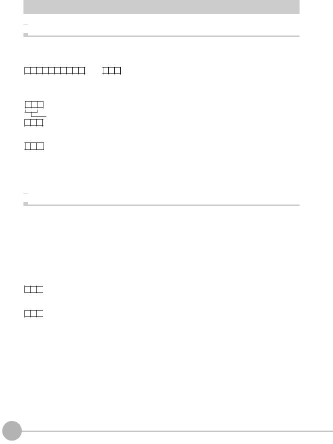
Acquiring/Switching the Bank No. < BANK command >

 Acquiring a bank No.
This command acquires the current bank No.
< Command format >
B |
A |
N |
K |
CR |
or |
B |
K |
CR |
< Response format >
When processing ends successfully
CR
 Bank No. (max. 2 digits)
O K CR
When processing fails
E R CR
< Explanation of parameters >
Bank No. |
The acquired bank No. is returned. (0 to 31) |
|
|

 Switching to another bank
This command switches the bank to be used.
< Command format >
B |
A |
N |
K |
|
|
|
CR |
|
or |
B |
K |
|
|
|
CR |
|
|
|
|
|
|
|
|
|
|
|
Bank No. |
|
|
|
|
|
|
|
Bank No. |
|
|
|
|
|
|
|
|
|
|
|
|
|
|
|
|||
|
|
|
|
|
|
|
|
|
(max. 2 digits) |
|
|
|
|
|
|
|
(max. 2 digits) |
< Response format >
When processing ends successfully
O K CR
When processing fails
E R CR
< Explanation of parameters >
Bank No. |
Specifies the bank No. after the bank is switched. (0 to 31) |
|
|
|
|
11 |
|
ZFX-C Serial Communication Command Reference |
About Communication Commands |
||
|
Acquiring/Switching the Bank Group No. < BANKGROUP command >

 Acquiring a bank group No.
This command acquires the current bank group No.
< Command format >
B A N K G R O U P CR or B G CR
< Response format >
When processing ends successfully
CR
Bank group No. (max. 2 digits)
O K CR
When processing fails
E R CR
< Explanation of parameters >
Bank group No. |
The acquired bank group No. is returned. (0 to 31) |
|
|

 Switching bank group Nos.
This command switches the bank group to be used.
< Command format >
B |
A |
N |
K |
G |
R |
O |
U |
P |
|
|
|
CR |
|
or |
B |
G |
|
|
|
CR |
|
|
|
|
|
|
|
|
|
|
|
|
|
|
|
|
Bank group No. |
|
|
|
|
|
|
|
Bank group No. |
|
|
|
|
|
|
|
|
|
|
|
|
|
|
|
|
|
|
|
|
|||
|
|
|
|
|
|
|
|
|
|
|
|
|
|
(max. 2 digits) |
|
|
|
|
|
|
|
(max. 2 digits) |
< Response format >
When processing ends successfully
O K CR
When processing fails
E R CR
< Explanation of parameters >
Bank group No. |
Specifies the bank group No. after the bank group is switched. (0 to 31) |
|
|
12 |
About Communication Commands |
ZFX-C Serial Communication Command Reference |
|

Measurement Control/Measurement Value Acquisition
Commands
Acquiring the Measurement Result of the Measurement Item < MEASDATA command >
This command acquires the measurement result of the measurement item.
< Command format >
|
M |
E |
A |
S |
D |
A |
T |
A |
|
|
|
|
|
|
|
|
|
|
CR |
|
|
or |
M |
D |
|
|
|
|
|
|
|
|
|
|
CR |
|
|
|
|
|
|
|
|
|
|
|
|
|
|
|
|
|
|
|
|
|
|
|
|
|
|
||||||||||||
|
|
|
|
|
|
|
|
|
|
|
|
|
|
|
|
|
|
|
|
|
|
Data No. |
|
|
|
|
|
|
|
|
|
|
|
|
|
|
|
|
|
|
|
|
|
|
|
|
|
|
|
|
|
|
|
|
|
|
|
|
|
|
|
|
|
|
|
|
|
|
|
|
|
|
|
|
|
|
|
|
|
|
|
|
|
|
|
|
|
|
|
|
|
|
|
|
|
|
|
|
|
|
|
|
|
|
|
|
|
|
||
|
|
|
|
|
|
|
|
|
|
|
|
|
|
|
|
|
|
|
|
|
|
(max. 3 digits) |
|
|
|
|
|
|
|
|
|
|
|
|
|
|
|
|
|
|
|
|
|
|
|
|
|
|
|
|
|
|
|
|
|
|
|
Measurement |
|
|
|
|
|
|
|
|
|
|
|
|
|
|
|
|
|
|
|
|
|
|
|
|
|
|
|
|
|
|
|
|
|
|
|
|
item No. |
|
|
|
|
|
|
|
|
|
|
|
|
|
|
|
|
|
|
|
|
|
|
|
|
|
|
|
|
|
|
|
|
|
|
|
|
|
|
|
|
|
|
|
|
|
|
|
|
|
|
||
|
|
|
|
|
|
|
|
|
|
|
|
|
|
|
|
|
|
|
|
|
(max. 3 digits) |
|
|
|
|
|
|
|
|
|
|
|
|
|
|
|
< Response format > |
|
|
|
|
|
|
|
|
|
|
|
|
|
|
|
|
|
|
|
|
|
|
|
|
|
|
||||||||||
When processing ends successfully
Measurement value |
CR |
O K CR
Data No. (max. 3 digits)
Measurement item No. (max. 3 digits)
When processing fails
ER CR
<Explanation of parameters >
Measurement item No. |
Specifies the measurement item No. (0 to 127) |
|
|
|
|
Data No. |
Specifies the data No. (0 to 127) |
|
|
|
For details, see "Parameter List (p.31)." |
|
|
|
|
|
|
Measurement value |
The acquired measurement value is returned in ASCII code. |
|
|
The measurement value is not dependent on the format (ASCII/binary) specified in the |
|
|
output conditions. |
|
|
• Minus sign: -, plus sign: none |
|
|
• The size of the integer section is variable. |
|
|
• The decimal point is indicated by a period ".". |
|
|
• The maximum number of digits past the decimal point is three. |
|
|
|
|
|
|
13 |
|
ZFX-C Serial Communication Command Reference |
About Communication Commands |
||
|
 Loading...