


 Loading...
Cat. No. W446-E1-10
SYSMAC
WS02-CXPC_-V9
CX-Programmer Ver. 9
OPERATION MANUAL
SYSMAC
WS02-CXPC@-V9
CX-Programmer Ver. 9.@
Operation Manual
Revised December 2009

OMRON |
CX-Programmer – Operation Manual |
|
|
|
|
About this Manual (W446):
This manual describes the operation of the CX-Programmer and consists of the following three parts.
•Part 1: CX-Programmer
This part describes the CX-Programmer software that is a PLC Programming Device, and also provides the overall precautions and the version upgrades information.
•Part 2: CX-Server PLC Tools
This part describes the CX-Server PLC Tools software, which is a collection of the following components:
PLC Memory, IO Table, PLC Setup, Data Trace/Time Chart Monitor, PLC Error, Memory Card, PLC-Clock, and CX-Net Network Configuration (including Data Link Editor and Routing Table).
•Part 3: CX-Server Runtime
This part describes the CX-Server software that is a communications middleware.
Note: References within each part are references to the pages or chapters within that part.
Related Manual
For details on the function block functions and ST programming, refer to the CX-Programmer Operation Manual Function Blocks and Structured Text (Cat. No. W447).
For details on the SFC programming functions, refer to the CX-Programmer Operation Manual SFC (Cat. No. W469).
For details on procedures for installing the CX-Programmer from the CX-One FA Integrated Tool Package, refer to the CX-One Setup Manual provided with CX-One.
Cat. No. |
Model |
Manual name |
Contents |
|
|
|
|
W463 |
CXONE-AL@@C-V4/ |
CX-One Setup Manual |
Installation and overview of CX-One FA |
|
AL@@D-V4 |
|
Integrated Tool Package. |
|
|
|
|
WARNING: Failure to read and understand the information provided in this manual may result in personal injury or death, damage to the product, or product failure. Please read each chapter in its entirety and be sure you understand the information provided in the chapter and related chapters before attempting any of the procedures or operations given.
CX-Programmer_Page (ii)

OMRON |
CX-Programmer – Operation Manual |
|
|
|
|
Read and Understand this Manual
Please read and understand this manual before using the product. Please consult your OMRON representative if you have any questions or comments.
Warranty and Limitations of Liability
WARRANTY
(1)The warranty period for the Software is one year from either the date of purchase or the date on which the Software is delivered to the specified location.
(2)If the User discovers a defect in the Software (i.e., substantial non-conformity with the manual), and returns it to OMRON within the above warranty period, OMRON will replace the Software without charge by offering media or downloading services from the Internet. And if the User discovers a defect in the media which is attributable to OMRON and returns the Software to OMRON within the above warranty period, OMRON will replace the defective media without charge. If OMRON is unable to replace the defective media or correct the Software, the liability of OMRON and the User’s remedy shall be limited to a refund of the license fee paid to OMRON for the Software.
LIMITATIONS OF LIABILITY
(1)THE ABOVE WARRANTY SHALL CONSTITUTE THE USER’S SOLE AND EXCLUSIVE REMEDIES AGAINST OMRON AND THERE ARE NO OTHER WARRANTIES, EXPRESSED OR IMPLIED, INCLUDING BUT NOT LIMITED TO, WARRANTY OF MERCHANTABILITY OR FITNESS FOR A PARTICULAR PURPOSE. IN NO EVENT WILL OMRON BE LIABLE FOR ANY LOST PROFITS OR OTHER INDIRECT, INCIDENTAL, SPECIAL, OR CONSEQUENTIAL DAMAGES ARISING OUT OF USE OF THE SOFTWARE.
(2)OMRON SHALL ASSUME NO LIABILITY FOR DEFECTS IN THE SOFTWARE BASED ON MODIFICATION OR ALTERATION OF THE SOFTWARE BY THE USER OR ANY THIRD PARTY.
(3)OMRON SHALL ASSUME NO LIABILITY FOR SOFTWARE DEVELOPED BY THE USER OR ANY THIRD PARTY BASED ON THE SOFTWARE OR ANY CONSEQUENCE THEREOF.
CX-Programmer_Page (iv)

OMRON |
CX-Programmer – Operation Manual |
|
|
|
|
Application Considerations
SUITABILITY FOR USE
THE USER SHALL NOT USE THE SOFTWARE FOR A PURPOSE THAT IS NOT DESCRIBED IN THE ATTACHED USER MANUAL.
CX-Programmer_Page (v)

OMRON |
CX-Programmer – Operation Manual |
|
|
|
|
Disclaimers
CHANGE IN SPECIFICATIONS
The software specifications and accessories may be changed at any time based on improvements or for other reasons.
EXTENT OF SERVICE
The license fee of the Software does not include service costs, such as dispatching technical staff.
ERRORS AND OMISSIONS
The information in this manual has been carefully checked and is believed to be accurate; however, no responsibility is assumed for clerical, typographical, or proofreading errors, or omissions.
CX-Programmer_Page (vi)

OMRON |
CX-Programmer – Operation Manual |
|
|
|
|
Precautions
Intended Audience
General Precautions


 WARNING
Safety Precautions


 WARNING
This manual is intended for the following personnel, who must also have knowledge of electrical systems (an electrical engineer or the equivalent).
•Personnel in charge of installing FA systems.
•Personnel in charge of designing FA systems.
•Personnel in charge of managing FA systems and facilities.
The user must operate the product according to the performance specifications described in the operation manuals.
Before using the product under conditions which are not described in the manual or applying the product to nuclear control systems, railroad systems, aviation systems, vehicles, combustion systems, medical equipment, amusement machines, safety equipment, and other systems, machines, and equipment that may have a serious influence on lives and property if used improperly, consult your OMRON representative.
Make sure that the ratings and performance characteristics of the product are sufficient for the systems, machines, and equipment, and be sure to provide the systems, machines, and equipment with double safety mechanisms.
This manual provides information for programming and operating the Unit. Be sure to read this manual before attempting to use the Unit and keep this manual close at hand for reference during operation.
It is extremely important that a PLC and all PLC Units be used for the specified purpose and under the specified conditions, especially in applications that can directly or indirectly affect human life. You must consult with your OMRON representative before applying a PLC System to the above-mentioned applications.
Confirm safety sufficiently before transferring I/O memory area status from the CX-Programmer to the PLC. The devices connected to Output Units may malfunction, regardless of the operating mode of the CPU Unit. Caution is required in respect to the following functions.
•Transferring from the CX-Programmer to real I/O (CIO Area) in the CPU Unit using the PLC Memory window.
•Transferring from file memory to real I/O (CIO Area) in the CPU Unit using the Memory Card window.
CX-Programmer_Page (vii)
OMRON |
|
|
CX-Programmer – Operation Manual |
|
|
|
WARNING |
Observe the following precautions when using the PLC Backup Tool. |
|
|
|
• Sufficiently check the data that is selected for restoring before performing |
||
|
|
|
||
|
|
|
the next step. If the correct data is not restored, unexpected operation |
|
|
|
|
may occur in the controlled system after the data is restored. |
|
•Some Special I/O Units and CPU Bus Units operate with parameters that are stored in the CPU Unit. If one of these Units is selected for backup, restrictions will be displayed in the Comments Area of the Backup from PLC Dialog Box. Confirm the restrictions, and always select the Special I/O Unit or CPU Bus Unit together with the CPU Unit when backing up or restoring data. If the data from both Units is not backed up or restored together, unexpected operation may occur in the controlled system.
•If there are any backup restrictions for the Units to which data is being restored, the restrictions will be displayed in the Comments Area of the Backup from PLC Dialog Box. Confirm the restrictions, and always take the required measures. If required measures are not taken, unexpected operation may occur in the controlled system after the data is restored.
•Forced status can be backed up, but it cannot be restored. If you restored data that contained forced status, use the CX-Programmer after restoring the data to force-set or force-reset bits as required. If required bits are not force-set or force-reset, differences in the forced status in memory may cause unexpected operation of the controlled system.
•Confirm that stopping PLC operation will not create any problems before restoring data during PLC operation. If the PLC stops at an unanticipated time, unexpected operation may occur in the controlled system.
•Always turn the power supply to the PLC OFF and then ON after restoring data. If the power supply is not turned OFF and then ON, memory in the PLC may not be updated to the restored data, which may cause unexpected operation of the controlled system.
Caution |
Observe the following precaution when specifying a symbol or word |
|
address for an array variable index in a ladder program or when specifying |
|
a symbol for an array variable index in an ST program. |
When using a symbol or address to indirectly specify the element number of an array variable, be sure that the resulting address is not outside the memory area that contains the first word in the array. For example, use a symbol comparison instruction or an IF statement to ensure that processing is performed only when the memory area is not exceeded. If an element number that exceeds the memory area is specified, data in another memory area will be read or written, possibly resulting in unexpected operation.
Caution |
Observe the following precaution when specifying a symbol or word |
|
address for an offset in a ladder program. |
When using a symbol or address to indirectly specify an offset for a memory address, be sure that the resulting address is not outside the memory area that contains original address. For example, use a symbol comparison instruction to ensure that processing is performed only when the memory area is not exceeded. If the final address (i.e., the original address plus the specified offset) exceeds the memory area, data in another memory area will be read or written, possibly resulting in unexpected operation.
CX-Programmer_Page (viii)
OMRON |
|
|
|
|
|
|
|
CX-Programmer – Operation Manual |
||||||||||||
|
|
|
Caution |
Confirm safety at the destination node before transferring a program to |
|
|||||||||||||||
|
|
|
|
|
|
|
|
|
|
another node or changing contents of the I/O memory area. Doing either of |
||||||||||
|
|
|
|
|
|
|
|
|
|
these without confirming safety may result in injury. |
|
|
||||||||
|
|
|
Caution |
Execute online edit only after confirming that no adverse effects will be |
||||||||||||||||
|
|
|
|
|
|
|
|
|
|
caused by extending the cycle time. Otherwise, the input signals may not |
||||||||||
|
|
|
|
|
|
|
|
|
|
be readable. |
|
|
|
|
|
|||||
|
|
|
Caution |
If synchronous unit operation is being used, perform online editing only |
||||||||||||||||
|
|
|
|
|
|
|
|
|
|
after confirming that an increased synchronous processing time will not |
||||||||||
|
|
|
|
|
|
|
|
|
|
affect the operation of the main and slave axes. |
|
|
||||||||
|
|
|
Caution |
Confirm safety sufficiently before monitoring power flow and present value |
||||||||||||||||
|
|
|
|
|
|
|
|
|
|
status in the Ladder Section window or when monitoring present values in |
||||||||||
|
|
|
|
|
|
|
|
|
|
the Watch window. If force-set/reset or set/reset operations are |
||||||||||
|
|
|
|
|
|
|
|
|
|
inadvertently performed by pressing short-cut keys, the devices connected |
||||||||||
|
|
|
|
|
|
|
|
|
|
to Output Units may malfunction, regardless of the operating mode of the |
||||||||||
|
|
|
|
|
|
|
|
|
|
CPU Unit. |
|
|
|
|
|
|||||
|
|
|
Caution |
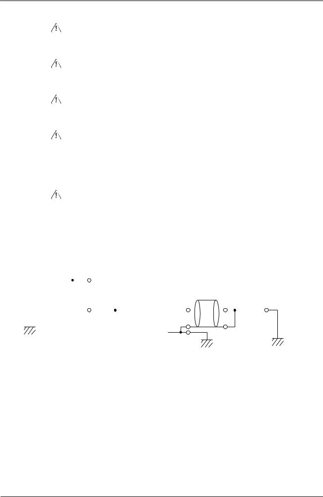
Caution is required when connecting peripheral devices, such as a |
||||||||||||||||
|
|
|
|
|
|
|
|
|
|
personal computer, to the PLC when Units with non-isolated power |
||||||||||
|
|
|
|
|
|
|
|
|
|
supplies, such as the CS1W-CLK12/CLK52(-V1), that are connected to an |
||||||||||
|
|
|
|
|
|
|
|
|
|
external power supply are mounted to the PLC. If the 24-V side is grounded |
||||||||||
|
|
|
|
|
|
|
|
|
|
on the external power supply, a short will be created if the 0-V side of the |
||||||||||
|
|
|
|
|
|
|
|
|
|
peripheral device is grounded. When connecting peripheral devices, either |
||||||||||
|
|
|
|
|
|
|
|
|
|
ground the 0-V side of the external power supply or do not ground the |
||||||||||
|
|
|
|
|
|
|
|
|
|
external power supply at all. |
|
|
|
|
||||||
|
|
|
|
|
|
|
|
|
|
|
|
|
|
|
|
|
|
|
|
|
|
|
|
|
|
|
|
|
|
|
Non-isolated |
|
|
|
|
|
|
||||
|
|
|
|
|
|
|
24-VDC |
power supplies |
|
|
|
|
|
|
||||||
|
|
|
|
|
|
|
|
|
|
|
|
|
|
|
|
|
|
|||
|
|
|
|
|
|
|
|
|
|
|
|
|
|
|
|
|
|
|
||
|
External power |
|
|
|
|
|
|
|
|
|
|
|
|
Cable |
|
|
|
|||
|
|
|
|
|
|
|
|
|
|
|
|
|
|
|
||||||
|
supply |
|
|
|
|
|
|
|
|
|
|
|
|
|||||||
|
|
|
|
|
|
|
0-VDC |
|
|
0-VDC |
|
|
|
0-VDC |
|
|
||||
|
FG |
|
|
|
|
|
|
|
|
|
|
|
||||||||
|
|
|
|
|
|
|
|
|
|
|
|
|
|
|
|
FG |
FG |
|
FG |
|
|
|
|
|
|
|
|
|
|
|
|
|
|
|
|
|
|
||||
|
|
|
|
|
|
|
|
|
|
|
|
|
|
|
|
|
|
|||
|
|
|
|
|
|
|
|
|
|
Controller Link unit |
CPU unit |
Peripheral devices |
|
|
||||||
|
|
|
|
|
|
|
|
|
|
|
|
|
||||||||
CX-Programmer_Page (ix)

OMRON |
CX-Programmer – Operation Manual |
|
|
|
|
Application Precaution
Observe the following precautions when using the CX-Programmer.
•Observe the following precautions before starting the CX-Programmer.
•Exit all applications not directly related to the CX-Programmer. Particularly exit any software such as screen savers, virus checkers, email or other communications software, and schedulers or other applications that start up periodically or automatically.
•Disable sharing hard disks, printers, or other devices with other computers on any network.
•With some notebook computers, the RS-232C port is allocated to a modem or an infrared port by default. Follow the instructions in documentation for your computer and enable using the RS-232C port as a normal serial port.
•With some notebook computers, the default settings for saving energy do not supply the rated power to the RS-232C port. There may be both Windows settings for saving energy, as well as setting for specific computer utilities and BIOS. Following the instructions in documentation for your computer, disable all energy saving settings.
•Do not turn OFF the power supply to the PLC or disconnect the connecting cable while the CX-Programmer is online with the PLC. The computer may malfunction.
•With the CS/CJ-series PLCs, when creating an AUTOEXEC.IOM file from the CX-Programmer to automatically transfer data at startup, set the first write address to D20000 and be sure that the size of data written does not exceed the size of the DM Area. When the data file is read from the Memory Card at startup, data will be written in the CPU Unit starting at D20000 even if another address was set when the AUTOEXEC.IOM file was created. Also, if the DM Area is exceeded (which is possible when the CX-Programmer is used), the remaining data will be written to the EM Area. Refer to information on file operations in the CS/CJ-series Programming Manual for details.
•Confirm that no adverse effect will occur in the system before attempting
any of the following. Not doing so may result in an unexpected operation. Changing the operating mode of the PLC.
•Force-setting/force-resetting any bit in memory.
•Changing the present value of any word or any set value in memory.
•Check the user program for proper execution before actually running it on the Unit. Not checking the program may result in an unexpected operation.
•Precaution on Using Indirect DM and EM Addresses in Comparison Instructions:
When indirect DM or EM addresses are used as operands in comparison instructions, the top portion of the comparison instruction will be displayed in yellow when it is being monitored. At that time the power flow will not be monitored to the right of such comparison instructions. The contact and coil status, and present values of operands in special instructions will be displayed normally.
CX-Programmer_Page (x)

OMRON |
CX-Programmer – Operation Manual |
|
|
|
|
•The user program and parameter area data in CS1-H CPU Units is backed up in the built-in flash memory. The BKUP indicator will light on the front of the CPU Unit when the backup operation is in progress. Do not turn OFF the power supply to the CPU Unit when the BKUP indicator is lit. The data will not be backed up if power is turned OFF.
To display the status of writing to flash memory on the CX-Programmer, place a checkmark by Display dialog to show PLC Memory Backup Status on the PLC properties and then select Windows | PLC Memory Backup Status from the Windows menu.
•Precaution in Changing the PLC Type
On the CX-Programmer, you can change the PLC (device) type or CPU type. When these are changed, however, only the data for the ladder program and the symbol tables are changed. The following data will be initialized and must be reset.
•PLC Setup
•Expansion instructions
•I/O tables
•PLC memory
Particularly the PLC Setup has a large impact on PLC system operation. Be careful to reset all require settings after changing the PLC type.
If expansion instruction allocations are not reset, program errors could occur, preventing the PLC from running. Always restore the expansion instruction allocates to the previous settings after changing the PLC type.
CX-Programmer_Page (xi)

OMRON |
CX-Programmer – Operation Manual |
|
|
|
|
Observe the following precautions when using the CX-Net.
•Do not change the operating mode of the CPU Unit without first confirming that operation of the controlled system will not be affect.
•Do not run the user program on the PLC until its operation has been checked sufficiently.
•The data link mode (manual setting or automatic setting) and data link method are determined according to the data link setting in the startup node. In the startup node, set a data link table in the case of manual setting and data link automatic setting parameters in the case of automatic setting. If the settings are incorrect, the data link will not start.
•Check the following items before starting data links. If incorrect data link tables or parameters are set, injury may result due to unexpected operation of the system. Even if the correct data link tables and parameters have been set, do not start or stop data links before verifying that there will be no adverse influence on the system.
(1)Manually Set Data Links
Check the data link tables in each node participating in the data link to see that they are correct.
Be sure that data link tables are deleted from nodes that are not participating in the data links.
(2) Automatically Set Data Links
Be sure that the correct DM parameters have been set in the data link startup node.
•CPU Bus Units will be automatically restarted when routing tables are transferred from a Programming Device to the CPU Unit. Resetting is required to use the new tables. Confirm that restarting the CPU Bus Units will not adversely affect system operation before transferring routing tables.
•When Special I/O Unit or CPU Unit settings are performed in the I/O Table Window and then transferred from the PLC Memory Window, the following warning will be displayed if the allocated DM Area/CIO Area addresses set for Special I/O Units or CPU Bus Units in the I/O Table Window on the computer overlap with the PLC data table addresses. Unless the CPU Bus Unit or Special I/O Unit settings have been previously transferred to the CPU Unit and the allocated DM Area/CIO Area data in the PLC data table for Special I/O Units or CPU Bus Units is to be overwritten, always click the No Button, shift the address, and repeat the transfer procedure.
•CPU Bus Unit and Special I/O Unit settings are not checked for logical consistency. Be very careful of the logical consisting of the overall settings when making any setting that affects other settings, e.g., settings that enable or disable other settings. Transfer the Special I/O Unit or CPU Bus Unit settings to the PLC and then start operation, being aware that any logical inconsistencies may produce unexpected operation.
•For example, if one setting selects either user settings or default settings and is set to use the default settings, it will not automatically change to enable user settings even if the related user settings are made. To use the user settings, they will have to be enabled manually and specifically in the setting that selects either user settings or default settings.
CX-Programmer_Page (xii)
Unit Versions of CS/CJ/CP-series CPU Units
Unit Versions
A “unit version” has been introduced to manage CPU Units in the CS/CJ/CP
Series according to differences in functionality accompanying Unit upgrades.
This applies to the CJ2, CS1-H, CJ1-H, CJ1M, CS1D, CP1H, CP1L, and
CP1E CPU Units.
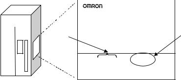
Notation of Unit Versions on Products
The unit version is given to the right of the lot number on the nameplate of the products for which unit versions are being managed, as shown below.
CS/CJ/CP-series CPU Unit |
Produce nameplate |
|||||
|
|
|
|
|
|
|
|
|
|
|
|
CS1H-CPU67H |
|
|
|
|
|
|
CPU UNIT |
|
|
|
|
|
|
||
|
|
|
Lot No. |
|
|
Unit version |
|
|
|
|
|
||
|
|
|
|
|
||
Example for unit version 3.0
|
Lot No. 040715 0000 |
Ver.3.0 |
|
||
|
OMRON Corporation |
MADE IN JAPAN |
|
•CS1-H, CJ1-H, and CJ1M CPU Units (except for low-end models) manufactured on or before November 4, 2003 do not have a unit version given on the CPU Unit (i.e., the location for the unit version shown above is blank).
•The unit version of the CJ1-H-R CPU Units begins at version 4.0.
•The unit version of the CS1-H, CJ1-H, and CJ1M CPU Units, as well as the CS1D CPU Units for Single-CPU Systems, begins at version 2.0.
•The unit version of the CS1D CPU Units for Duplex-CPU Systems begins at version 1.1.
•The unit version of the CP1H/CP1L/CP1E CPU Units begins at version 1.0, except for the CP1H-Y@@@@-@, for which the unit version begins at version 1.1.
•CPU Units for which a unit version is not given are called Pre-Ver. @.@
CPU Units, such as Pre-Ver. 2.0 CPU Units and Pre-Ver. 1.1 CPU Units.
Confirming Unit Versions with Support Software
CX-Programmer version 4.0 can be used to confirm the unit version using one of the following two methods.
•Using the PLC Information
•Using the Unit Manufacturing Information (This method can be used for Special I/O Units and CPU Bus Units as well.)
Note CX-Programmer version 3.3 or lower cannot be used to confirm unit versions.
PLC Information
•If you know the device type and CPU type, select them in the Change PLC Dialog Box, go online, and select PLC - Edit - Information from the menus.
•If you don’t know the device type and CPU type, but are connected directly to the CPU Unit on a serial line, select PLC - Auto Online to go online, and then select PLC - Edit - Information from the menus.
In either case, the following PLC Information Dialog Box will be displayed.
CX-Programmer_Page (xiii)
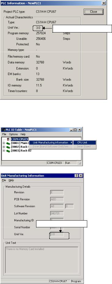
Unit version
Use the above display to confirm the unit version of the CPU Unit.
Unit Manufacturing Information
In the IO Table Window, right-click and select Unit Manufacturing information - CPU Unit.
The following Unit Manufacturing information Dialog Box will be displayed
Unit version
Use the above display to confirm the unit version of the CPU Unit connected online.
CX-Programmer_Page (xiv)
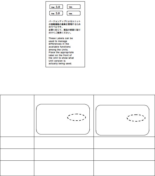
Using the Unit Version Labels
The following unit version labels are provided with the CPU Unit.
These labels can be attached to the front of previous CPU Units to differentiate between CPU Units of different unit versions.
Unit Version Notation
In this manual, the unit version of a CPU Unit is given as shown in the following table.
Product nameplate CPU Units on which no unit version is |
Units on which a version is given |
given |
(Ver. @.@) |
Lot No. XXXXXX XXXX |
Lot No. XXXXXX XXXX |
Ver.@.@ |
OMRON Corporation |
MADE IN JAPAN |
|
Meaning
Designating individual
CPU Units (e.g., the Pre-Ver. 2.0 CS1-H CPU Units CS1H-CPU67H CPU Unit Ver. @.@ CS1H-CPU67H)
Designating groups of
CPU Units (e.g., the Pre-Ver. 2.0 CS1-H CPU Units CS1-H CPU Units Ver. @.@ CS1-H CPU Units)
Designating an entire
series of CPU Units
Pre-Ver. 2.0 CS-series CPU Units CS-series CPU Units Ver. @.@
(e.g., the CS-series CPU Units)
CX-Programmer_Page (xv)

Unit Versions and Lot Numbers
CX-Programmer_Page (xvi)
Function Support by Unit Version
CS1-H CPU Units (CS1@-CPU@@H)
|
Function |
Unit version |
||
|
|
Pre-Ver. 2.0 CPU |
CPU Units Ver. 2.0 or |
|
|
|
Units |
later |
|
Downloading and Uploading Individual Tasks |
--- |
OK |
||
Improved Read Protection Using Passwords |
--- |
OK |
||
Write Protection from FINS Commands Sent to CPU Units via |
--- |
OK |
||
Networks |
|
|
|
|
Online Network Connections without I/O Tables |
--- |
OK |
||
Communications through a Maximum of 8 Network Levels |
--- |
OK |
||
Connecting Online to PLCs via NS-series PTs |
OK from lot number |
OK |
||
|
|
030201 |
|
|
Setting First Slot Words |
OK for up to 8 groups |
OK for up to 64 groups |
||
Automatic Transfers at Power ON without a Parameter File |
--- |
OK |
||
Automatic Detection of I/O Allocation Method for Automatic |
--- |
--- |
||
Transfer at Power ON |
|
|
||
Operation Start/End Times |
--- |
OK |
||
New |
MILH, MILR, MILC |
--- |
OK |
|
Application |
=DT, <>DT, <DT, <=DT, >DT, >=DT |
--- |
OK |
|
Instructions |
||||
BCMP2 |
--- |
OK |
||
|
||||
|
GRY |
OK from lot number |
OK |
|
|
|
030201 |
|
|
|
TPO |
--- |
OK |
|
|
DSW, TKY, HKY, MTR, 7SEG |
--- |
OK |
|
|
EXPLT, EGATR, ESATR, ECHRD, ECHWR |
--- |
OK |
|
|
Reading/Writing CPU Bus Units with IORD/IOWR |
OK from lot number |
OK |
|
|
|
030418 |
|
|
|
PRV2 |
--- |
--- |
|
CX-Programmer_Page (xvii)
CS1D CPU Units
|
|
Function |
CS1D CPU Units for Duplex-CPU |
CS1D CPU Units |
|
|
|
|
Systems (CS1D-CPU@@H) |
for Single-CPU |
|
|
|
|
Systems |
||
|
|
|
|
|
|
|
|
|
|
|
(CS1D-CPU@@S) |
|
|
|
Pre-Ver. 1.1 CPU |
CPU Unit Ver. 1.1 |
CPU Unit Ver. 2.0 |
|
|
|
Units |
|
or later |
Functions |
|
Duplex CPU Units |
OK |
OK |
--- |
unique to |
|
Online Unit Replacement |
OK |
OK |
OK |
CS1D CPU |
|
||||
|
|
|
|
|
|
Units |
|
Duplex Power Supply Units |
OK |
OK |
OK |
|
|
Duplex Controller Link Units |
OK |
OK |
OK |
|
|
Duplex Ethernet Units |
--- |
OK |
OK |
Downloading and Uploading Individual Tasks |
--- |
--- |
OK |
||
Improved Read Protection Using Passwords |
--- |
--- |
OK |
||
Write Protection from FINS Commands Sent |
--- |
--- |
OK |
||
to CPU Units via Networks |
|
|
|
||
Online Network Connections without I/O |
--- |
--- |
OK |
||
Tables |
|
|
|
|
|
Communications through a Maximum of 8 |
--- |
--- |
OK |
||
Network Levels |
|
|
|
||
Connecting Online to PLCs via NS-series |
--- |
--- |
OK |
||
PTs |
|
|
|
|
|
Setting First Slot Words |
--- |
--- |
OK for up to 64 |
||
|
|
|
|
|
groups |
Automatic Transfers at Power ON without a |
--- |
--- |
OK |
||
Parameter File |
|
|
|
|
|
Automatic Detection of I/O Allocation Method |
--- |
--- |
--- |
||
for Automatic Transfer at Power ON |
|
|
|
||
Operation Start/End Times |
--- |
OK |
OK |
||
New |
|
MILH, MILR, MILC |
--- |
--- |
OK |
Application |
|
=DT, <>DT, <DT, <=DT, >DT, |
--- |
--- |
OK |
Instructions |
|
||||
|
>=DT |
|
|
|
|
|
|
|
|
|
|
|
|
BCMP2 |
--- |
--- |
OK |
|
|
GRY |
--- |
--- |
OK |
|
|
TPO |
--- |
--- |
OK |
|
|
DSW, TKY, HKY, MTR, 7SEG |
--- |
--- |
OK |
|
|
EXPLT, EGATR, ESATR, |
--- |
--- |
OK |
|
|
ECHRD, ECHWR |
|
|
|
|
|
Reading/Writing CPU Bus |
--- |
--- |
OK |
|
|
Units with IORD/IOWR |
|
|
|
|
|
PRV2 |
--- |
--- |
--- |
CX-Programmer_Page (xviii)
CJ1-H/CJ1M CPU Units
Function |
|
CJ1-H CPU Units |
|
CJ1M CPU Units |
|
||
|
|
|
|
|
|
|
|
|
|
|
(CJ1H-CPU@@H-R) |
CJ1M-CPU12/13/22/23 |
CJ1M- |
||
|
|
|
(CJ1@-CPU@@H) |
|
|
CPU11/21 |
|
|
|
|
(CJ1G-CPU@@P) |
|
|
|
|
|
|
|
Pre-Ver. 2.0 |
CPU Units |
Pre-Ver. 2.0 |
CPU Units |
CPU Units |
|
|
|
CPU Units |
Ver. 2.0 |
CPU Units |
Ver. 2.0 |
Ver. 2.0 or |
|
|
|
|
|
|
|
later |
Downloading and Uploading |
--- |
OK |
--- |
OK |
OK |
||
Individual Tasks |
|
|
|
|
|
||
Improved Read Protection |
--- |
OK |
--- |
OK |
OK |
||
Using Passwords |
|
|
|
|
|
||
Write Protection from FINS |
--- |
OK |
--- |
OK |
OK |
||
Commands Sent to CPU Units |
|
|
|
|
|
||
via Networks |
|
|
|
|
|
|
|
Online Network Connections |
OK, but only if |
OK |
OK, but only if |
OK |
OK |
||
without I/O Tables |
I/O table |
|
I/O table |
|
|
||
|
|
|
allocation at |
|
allocation at |
|
|
|
|
|
power ON is set |
|
power ON is set |
|
|
Communications through a |
OK for up to 8 |
OK for up to 64 |
OK for up to 8 |
OK for up to 64 |
OK for up to 64 |
||
Maximum of 8 Network Levels |
groups |
groups |
groups |
groups |
groups |
||
Connecting Online to PLCs via |
OK from lot |
OK |
OK from lot |
OK |
OK |
||
NS-series PTs |
number 030201 |
|
number 030201 |
|
|
||
Setting First Slot Words |
--- |
OK |
--- |
OK |
OK |
||
Automatic Transfers at Power |
--- |
OK |
--- |
OK |
OK |
||
ON without a Parameter File |
|
|
|
|
|
||
Automatic Detection of I/O |
--- |
OK |
--- |
OK |
OK |
||
Allocation Method for |
|
|
|
|
|
||
Automatic Transfer at Power |
|
|
|
|
|
||
ON |
|
|
|
|
|
|
|
Operation Start/End Times |
--- |
OK |
--- |
OK |
OK |
||
New |
|
MILH, MILR, |
--- |
OK |
--- |
OK |
OK |
Application |
|
MILC |
|
|
|
|
|
Instructions |
|
=DT, <>DT, <DT, |
--- |
OK |
--- |
OK |
OK |
|
|
<=DT, >DT, |
|
|
|
|
|
|
|
>=DT |
|
|
|
|
|
|
|
BCMP2 |
--- |
OK |
OK |
OK |
OK |
|
|
GRY |
OK from lot |
OK |
OK from lot |
OK |
OK |
|
|
|
number 030201 |
|
number 030201 |
|
|
|
|
TPO |
--- |
OK |
--- |
OK |
OK |
|
|
DSW, TKY, HKY, |
--- |
OK |
--- |
OK |
OK |
|
|
MTR, 7SEG |
|
|
|
|
|
|
|
EXPLT, EGATR, |
--- |
OK |
--- |
OK |
OK |
|
|
ESATR, ECHRD, |
|
|
|
|
|
|
|
ECHWR |
|
|
|
|
|
|
|
Reading/Writing |
--- |
OK |
--- |
OK |
OK |
|
|
CPU Bus Units |
|
|
|
|
|
|
|
with IORD/IOWR |
|
|
|
|
|
|
|
PRV2 |
--- |
--- |
--- |
OK, but only for |
OK, but only for |
|
|
|
|
|
|
models with |
models with |
|
|
|
|
|
|
built-in I/O |
built-in I/O |
CX-Programmer_Page (xix)
Functions Supported by Unit Version 3.0 or Later
CS1-H CPU Units (CS1@-CPU@@H)
|
Function |
|
Unit version |
|
|
|
|
|
|
|
|
|
|
Pre-Ver. 2.0, Ver. |
Ver. 3.0 |
Ver. 4.0 |
|
|
|
2.0 |
|
(See note.) |
|
|
|
|
|
|
|
Function blocks (supported for CX-Programmer Ver. |
--- |
OK |
OK |
||
5.0 or higher) |
|
|
|
|
|
|
|
|
|
|
|
Serial Gateway (converting FINS commands to |
--- |
OK |
OK |
||
CompoWay/F commands at the built-in serial port) |
|
|
|
||
|
|
|
|
|
|
Comment memory (in internal flash memory) |
--- |
OK |
OK |
||
|
|
|
|
|
|
Expanded simple backup data |
--- |
OK |
OK |
||
|
|
|
|
|
|
New |
TXDU(256), RXDU(255) (support |
--- |
OK |
OK |
|
application |
no-protocol communications with |
|
|
|
|
instructions |
Serial Communications Units with |
|
|
|
|
|
unit version 1.2 or later) |
|
|
|
|
|
|
|
|
|
|
|
Model conversion instructions: |
--- |
OK |
OK |
|
|
XFERC(565), DISTC(566), |
|
|
|
|
|
COLLC(567), MOVBC(568), |
|
|
|
|
|
BCNTC(621) |
|
|
|
|
|
|
|
|
|
|
|
Special function block instructions: |
--- |
OK |
OK |
|
|
GETID(286) |
|
|
|
|
|
|
|
|
|
|
Additional |
TXD(235) and RXD(236) |
--- |
OK |
OK |
|
instruction |
instructions (support no-protocol |
|
|
|
|
functions |
communications with Serial |
|
|
|
|
|
Communications Boards with unit |
|
|
|
|
|
version 1.2 or later) |
|
|
|
|
|
|
|
|
|
|
New |
ASCII conversion instructions |
--- |
--- |
OK |
|
application |
(NUMBER-TO-ASCII and ASCII- |
|
|
|
|
instructions |
TONUMBER) |
|
|
|
|
|
Text File Write (TWRIT) |
|
|
|
|
|
|
|
|
|
|
Improved |
Online editing of function blocks |
--- |
--- |
OK |
|
function block |
|
|
|
|
|
Input-output variables are |
--- |
--- |
OK |
||
(FB) functions |
|||||
supported. |
|
|
|
||
|
|
|
|
||
|
(Input-output variables can be |
|
|
|
|
|
specified in arrays.) |
|
|
|
|
|
|
|
|
|
|
|
The STRING data type and text- |
--- |
--- |
OK |
|
|
string processing functions are |
|
|
|
|
|
supported in ST language. |
|
|
|
|
|
|
|
|
|
|
Using ST language programming in tasks |
--- |
--- |
OK with CX- |
||
|
|
|
|
Programmer Ver. 7.2 |
|
|
|
|
|
or higher |
|
|
|
|
|
||
Using SFC programming in tasks |
--- |
--- |
OK with CX- |
||
|
|
|
|
Programmer Ver. 7.2 |
|
|
|
|
|
or higher |
|
|
|
|
|
|
|
Note: CX-Programmer version 7.0 or higher is required to use functions added for unit version 4.0. Additional functions are supported if CX-Programmer version 7.2 or higher is used.
CS1D CPU Units
Unit version 3.0 (Ver. 3.0) is not supported.
CX-Programmer_Page (xx)
CJ1-H/CJ1M CPU Units (CJ1@-CPU@@H, CJ1M-CPU@@)
|
Function |
|
Unit version |
|
|
|
|
|
|
|
|
|
|
Pre-Ver. 2.0, |
Ver. 3.0 |
Ver. 4.0 |
|
|
|
Ver. 2.0 |
|
(See note.) |
|
|
|
|
|
|
|
Function blocks (supported for CX-Programmer Ver. |
--- |
OK |
OK |
||
5.0 or higher) |
|
|
|
|
|
|
|
|
|
|
|
Serial Gateway (converting FINS commands to |
--- |
OK |
OK |
||
CompoWay/F commands at the built-in serial port) |
|
|
|
||
|
|
|
|
|
|
Comment memory (in internal flash memory) |
--- |
OK |
OK |
||
|
|
|
|
|
|
Expanded simple backup data |
--- |
OK |
OK |
||
|
|
|
|
|
|
Additional |
PRV(881) and PRV2(883) |
--- |
OK |
OK |
|
instruction |
instructions: Added high-frequency |
|
|
|
|
functions |
calculation methods for calculating |
|
|
|
|
|
pulse frequency. (CJ1M CPU Units |
|
|
|
|
|
only) |
|
|
|
|
|
|
|
|
|
|
New |
TXDU(256), RXDU(255) (support |
--- |
OK |
OK |
|
application |
no-protocol communications with |
|
|
|
|
instructions |
Serial Communications Units with |
|
|
|
|
|
unit version 1.2 or later) |
|
|
|
|
|
|
|
|
|
|
|
Model conversion instructions: |
--- |
OK |
OK |
|
|
XFERC(565), DISTC(566), |
|
|
|
|
|
COLLC(567), MOVBC(568), |
|
|
|
|
|
BCNTC(621) |
|
|
|
|
|
|
|
|
|
|
|
Special function block instructions: |
--- |
OK |
OK |
|
|
GETID(286) |
|
|
|
|
|
|
|
|
|
|
Additional |
TXD(235) and RXD(236) |
--- |
OK |
OK |
|
instruction |
instructions (support no-protocol |
|
|
|
|
functions |
communications with Serial |
|
|
|
|
|
Communications Boards with unit |
|
|
|
|
|
version 1.2 or later) |
|
|
|
|
|
|
|
|
|
|
New |
ASCII conversion instructions |
--- |
--- |
OK |
|
application |
(NUMBER-To-ASCII and ASCII- |
|
|
|
|
instructions |
TO NUMBER) |
|
|
|
|
|
|
|
|
|
|
Improved |
Online editing of function blocks |
--- |
--- |
OK |
|
function block |
|
|
|
|
|
Input-output variables are |
--- |
--- |
OK |
||
(FB) functions |
|||||
supported. (Input-output variables |
|
|
|
||
|
|
|
|
||
|
can be specified in arrays.) |
|
|
|
|
|
|
|
|
|
|
|
The STRING data type and text- |
--- |
--- |
OK |
|
|
string processing functions are |
|
|
|
|
|
supported in ST language. |
|
|
|
|
|
|
|
|
|
|
Using ST language programming in tasks |
--- |
--- |
OK with CX- |
||
|
|
|
|
Programmer Ver. 7.2 |
|
|
|
|
|
or higher |
|
|
|
|
|
||
Using SFC programming in tasks |
--- |
--- |
OK with CX- |
||
|
|
|
|
Programmer Ver. 7.2 |
|
|
|
|
|
or higher |
|
|
|
|
|
|
|
Note: CX-Programmer version 7.0 or higher is required to use functions added for unit version 4.0. Additional functions are supported if CX-Programmer version 7.2 or higher is used.
CX-Programmer_Page (xxi)
Functions Supported by Unit Version for CJ2 CPU Units (CJ2H-CPU6@-EIP, CJ2HCPU6@)
Unit Version 1.2 or Later
CX-Programmer version 8.3 or higher must be used to enable using the functions added for unit version 1.2.
Unit |
CJ2H CPU Unit |
|
|
Model |
CJ2H-CPU6@-EIP |
|
CJ2H-CPU6@ |
|
|
Unit version |
Unit version 1.2 |
Item |
|
|
|
EM Area force-setting/resetting |
Supported. |
|
|
Unit Version 1.1 or Later
CX-Programmer version 8.1 or higher must be used to enable using the functions added for unit version 1.1.
Unit |
CJ2H CPU Unit |
|
|
|
|
Model |
CJ2H-CPU6@-EIP |
|
|
CJ2H-CPU6@ |
|
|
|
|
Unit version |
Unit version 1.1 |
Unit version 1.0 |
Item |
|
|
|
|
|
High-speed interrupt function |
Supported. |
Not supported. |
Decreased overhead time for interrupt tasks |
|
|
Minimum interval setting of 0.1 ms for Scheduled |
|
|
Interrupt Task |
|
|
|
|
|
Changing the minimum cycle time setting in |
Supported. |
Not supported. |
MONITOR mode |
|
|
|
|
|
Synchronous unit operation |
Supported. |
Not supported. |
Unit Version 1.0
All functions that are supported by unit version 4.0 or later of the CJ1 CPU Units are supported by unit version 1.0 of the CJ2 CPU Units.
CX-Programmer version 8.0 or higher must be used to enable using unit version 1.0 of the CJ2 CPU Units.
CX-Programmer_Page (xxii)

Functions Supported by Unit Version for CP-series CPU Units
Functions Supported by Unit Version 1.0 and 1.1
Functionality is the same as that for CS/CJ-series CPU Units with unit version 3.0. The functionality added for CS/CJ-series CPU Unit unit version 4.0 is not supported.
CP1H CPU Units
•CX-Programmer version 6.11 or higher is required to use CP1H-X@@@@- @/XA@@@@-@ with unit version 1.1 or 1.0.
•CX-Programmer version 6.20 or higher is required to use CP1H-Y@@@@- @ with unit version 1.1.
CPU Unit |
|
CP1H CPU Unit |
|
|
|
|
|
|
|
|
|
Model |
|
CP1H-@@@@-@ |
|
CP1H-Y@@@@-@ |
|
|
|
CP1H-XA@@@@-@ |
(See note 2.) |
||
|
|
(See note 1.) |
|
|
|
|
|
|
|
|
|
|
Unit version |
Ver. 1.1 or |
|
Ver. 1.0 |
Ver. 1.1 |
Function |
|
later |
|
|
|
|
|
|
|
|
|
|
|
|
|
|
|
Pulse |
Allocated built-in |
4 axes at |
|
2 axes at |
2 axes 100 kHz |
outputs |
I/O terminals |
100 kHz |
|
100 kHz |
|
|
|
|
|
2 axes at |
|
|
|
|
|
30 kHz |
|
|
|
|
|
|
|
|
Special pulse |
None |
|
2 axes at 1 kHz |
|
|
output terminals |
|
|
|
|
|
|
|
|
|
|
Note 1. The unit version for the CP1H-X@@@@-@/XA@@@@-@ begins at 1.0.
2.The unit version for the CP1H-X@@@@-@ begins at 1.1.
3.CX-Programmer version 7.11 or higher is required to use CP1L CPU Units with unit version 1.0.
CX-Programmer_Page (xxiii)
Unit Versions and Programming Devices
CX-Programmer version 4.0 or higher must be used to enable using the functions added for CPU Unit Ver. 2.0. The following tables show the relationship between unit versions and CX-Programmer versions.
Unit Versions and Programming Devices for CJ2 CPU Units
CPU Unit |
Functions |
|
Required Programming Device |
|
||
|
|
|
|
|
|
|
|
|
|
CX-Programmer |
|
|
|
|
|
|
|
|
|
|
|
|
Ver. 7.1 or lower |
Ver. 8.0 |
Ver. 8.1 |
Ver. 8.2 |
Ver. 8.3 |
|
|
|
|
|
|
|
CJ2H-CPU6@-EIP |
Functions for unit version |
× |
|
|
|
|
Unit version 1.0 |
1.0 |
|
|
|
|
|
|
|
|
|
|
|
|
CJ2H-CPU6@-EIP |
Functions added for unit |
× |
∆ |
|
|
|
Unit version 1.1 |
version 1.1 |
|
|
|
|
|
CJ2H-CPU6@ |
Functions added for unit |
× |
∆ |
|
|
|
Unit version 1.1 |
version 1.1 |
|
|
|
|
|
|
|
|
|
|
|
|
|
|
|
|
|
|
|
CJ2H-CPU6@-EIP |
Functions added for unit |
× |
∆ |
∆ |
∆ |
|
Unit version 1.2 |
version 1.2 |
|
|
|
|
|
CJ2H-CPU6@ |
Functions added for unit |
× |
∆ |
∆ |
∆ |
|
Unit version 1.2 |
version 1.2 |
|
|
|
|
|
|
|
|
|
|
|
|
|
|
|
|
|
|
|
×: Cannot be used, ∆: Can be used except for new functions added for unit versions, : Can be used
Note 1. It is not necessary to upgrade the version of the CX-Programmer if functionality that was enhanced for the upgrade of the CPU Unit will not be used.
2.CX-Programmer version 8.1 or higher is required to use the functions added for unit version 1.1. The high-speed interrupt function and changing the minimum cycle time setting in MONITOR mode, however, are also supported by CX-Programmer version 8.02.
3.A Programming Console cannot be used with a CJ2H CPU Unit.
Unit Versions and Programming Devices for CPU Units Other Than CJ2 CPU Units
CPU Unit |
Functions |
|
Required Programming Device |
|
|||
|
|
|
|
|
|
|
|
|
|
|
|
CX-Programmer |
|
|
|
|
|
|
|
|
|
|
|
|
|
Ver. 3.3 |
Ver. 4.0 |
Ver. 5.0 |
Ver. 7.0 |
Ver. 7.2 |
Ver. 8.0 |
|
|
|
|
Ver. 6.0 |
|
|
or later |
|
|
|
|
|
|
|
|
CS/CJ Series CPU |
Functions added for unit |
∆ |
∆ |
∆ |
|
|
|
Units, Unit Ver. 4.0 |
version 4.0 |
|
|
|
|
|
(See note |
|
|
|
|
|
|
|
4.) |
|
|
|
|
|
|
|
|
CS/CJ Series CPU |
Functions added for unit |
∆ |
∆ |
|
|
|
|
Units, Unit Ver. 3.0 |
version 3.0 |
|
|
|
|
|
|
|
|
|
|
|
|
|
|
CS/CJ Series CPU |
Functions added for unit |
∆ |
|
|
|
|
|
Units, Unit Ver. 2.0 |
version 2.0 |
|
|
|
|
|
|
|
|
|
|
|
|
|
|
CS1D CPU Units for |
Functions added for unit |
∆ |
|
|
|
|
|
Single-CPU Systems, |
version 2.0 |
|
|
|
|
|
|
Unit Ver. 2.0 |
|
|
|
|
|
|
|
|
|
|
|
|
|
|
|
CS1D CPU Units for |
Functions added for unit |
∆ |
|
|
|
|
|
Duplex-CPU Systems, |
version 1.1 |
|
|
|
|
|
|
Unit Ver.1.1 |
|
|
|
|
|
|
|
|
|
|
|
|
|
|
|
×: Cannot be used, ∆: Can be used except for new functions added for unit versions, : Can be used
Note 1. As shown above, there is no need to upgrade to CX-Programmer version 4.0 as long as the functions added for unit version 2.0 or unit version 1.1 are not used.
2.CX-Programmer version 7.0 or higher is required to use functions added for unit version 4.0. Additional functions are supported if CX-Programmer version 7.2 or higher is used.
3.Unit version 4.2 of the CJ1H-CPU6@-R is supported only by CX-Programmer version 8.0 or higher.
4.CX-Programmer version 8.0 or higher is required to use unit version 4.2 of the CJ1H- CPU6@-R.
CX-Programmer_Page (xxiv)
Unit Versions of CP-series CPU Units and Programming Devices
CPU Unit |
Model |
Unit |
|
CX-Programmer version |
|
|
|
|
version |
|
|
|
|
|
|
Ver. 6.11 |
Ver. 6.20 |
Ver. 7.11 |
Ver. 8.2 |
|
|
|
|
|
|
|
or later |
|
|
|
|
|
|
|
CP1H CPU Units |
CP1H-X@@@@-@ |
Ver. 1.1 |
OK |
OK |
OK |
OK |
|
CP1H-XA@@@@-@ |
Ver. 1.0 |
OK |
OK |
OK |
OK |
|
|
|
|
|
|
|
|
CP1H-Y@@@@-@ |
Ver. 1.1 |
--- |
OK |
OK |
OK |
|
|
|
|
|
|
|
CP1L CPU Units |
CP1L-M@@@@-@ |
Ver. 1.0 |
--- |
--- |
OK |
OK |
|
CP1L-L@@@@-@ |
|||||
|
|
|
|
|
|
|
|
|
|
|
|
|
|
CP1E CPU Units |
CP1E-E@@D@-A |
Ver. 1.0 |
--- |
--- |
--- |
OK |
|
CP1E-N@@D@-@ |
|||||
|
|
|
|
|
|
|
|
|
|
|
|
|
|
Note 1. Functionality of CP1H CPU Units with unit version 1.0 or 1.0 and CP1L CPU Units with unit version 1.0 is the same as that for CS/CJ-series CPU Units with unit version 3.0. The functionality added for CS/CJ-series CPU Unit unit version 4.0 is not supported.
2.There is no need to upgrade to CX-Programmer as long as the upgraded functionality is not used.
Device Type Setting
The unit version does not affect the setting made for the device type on the CX-Programmer. Select the device type as shown in the following table regardless of the unit version of the CPU Unit.
Series |
CPU Unit group |
CPU Unit model |
Device type setting on |
|
|
|
CX-Programmer |
|
|
|
|
CS Series |
CS1-H CPU Units |
CS1G-CPU@@H |
CS1G-H |
|
|
CS1H-CPU@@H |
CS1H-H |
|
CS1D CPU Units for Duplex-CPU Systems |
CS1D-CPU@@H |
CS1D-H (or CS1H-H) |
|
CS1D CPU Units for Single-CPU Systems |
CS1D-CPU@@S |
CS1D-S |
CJ Series |
CJ2 CPU Units |
CJ2H-CPU6@(-EIP) |
CJ2H |
|
CJ1-H CPU Units |
CJ1G-CPU@@H |
CJ1G-H |
|
|
CJ1GCPU@@P |
|
|
|
CJ1H-CPU@@H–R |
|
|
|
CJ1H-CPU@@H |
|
|
CJ1M CPU Units |
CJ1M-CPU@@ |
CJ1M |
CP Series |
CP1H CPU Units |
CP1H-X@@@@-@ |
CP1H |
|
|
CP1H-XA@@@@-@ |
|
|
|
CP1H-Y@@@@-@ |
|
|
CP1L CPU Units |
CP1L-M@@@@-@ |
CP1L |
|
|
CP1L-L@@@@-@ |
|
|
CP1E CPU Units |
CP1E-E@@D@-A |
CP1E |
|
|
CP1E-N@@D@-@ |
|
Note Device types not supported by the CX-Programmer version that is being used will not be displayed on the pull-down list of the Device type Field.
CX-Programmer_Page (xxv)
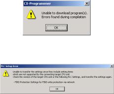
Troubleshooting Problems with Unit Versions on the CX-Programmer
Problem |
Cause |
Solution |
|
An attempt was made using CX- |
Check the program or change |
|
Programmer version 4.0 or |
the CPU Unit being |
|
higher to download a program |
downloaded to a CPU Unit |
|
containing instructions supported |
Ver. 2.0 or later. |
|
only by CPU Units Ver. 2.0 or |
|
After the above message is displayed, a compiling |
later to a Pre-Ver. 2.0 CPU Units. |
|
|
|
|
error will be displayed on the Compile Tab Page in |
|
|
the Output Window. |
|
|
|
An attempt was made using CX- |
Check the settings in the PLC |
|
Programmer version 4.0 or |
Setup or change the CPU Unit |
|
higher to download a PLC Setup |
being downloaded to a CPU |
|
containing settings supported |
Unit Ver. 2.0 or later. |
|
only by CPU Units Ver. 2.0 or |
|
|
later (i.e., not set to their default |
|
|
values) to a Pre-Ver. 2.0 CPU |
|
|
Units. |
|
"????" is displayed in a program transferred from the |
CX-Programmer version 3.3 or |
The new instructions cannot |
PLC to the CX-Programmer. |
lower was used to upload a |
be uploaded using CX- |
|
program containing instructions |
Programmer version 3.3 or |
|
supported only by CPU Units |
lower. Use CX-Programmer |
|
Ver. 2.0 or later from a CPU Unit |
version 4.0 or higher. |
|
Ver. 2.0 or later. |
|
CX-Programmer_Page (xxvi)
Loading...