


 Loading...
Cat. No. V03E-EN-0
NTXS
Programmable Terminals
USER´S MANUAL

Preliminary
Thank you for purchasing NTXS Series product from Omron. NTXS Series Products are versatile operator interfaces with Microsoft Windows® based configuration Software.
This manual will help you to safely install, configure and operate NTXS Products.
All the safety warnings and precautions must be followed to ensure proper unit performance and personal safety.
Warnings used in this manual:
DANGER
CAUTION
!
Danger Warnings are used to indicate situations, ocations and conditions that can cause serious injury or death.
Caution Warnings are used to indicate situations and conditions that can cause operator injury and/or unit damage.
If additional information or technical assistance is needed please contact:
Omron Europe B.V.
Wegalaan 67-69
NL-2132 JD Hoofddorp
The Netherlands
Phone :(+31)23-5681300
Fax :(+31)23 5681388
URL: www.omron-industrial.com
Manual Revisions:
If you contact us in reference to this manual, please include the following document number:
Name: |
NTXS Manual |
Document: |
V03E-EN-02 |
IMPORTANT
NTXS Series Products are intended to be operator interfaces, to work with PLCs which actually take control actions. It is assumed that the user is well acquainted with the PLC system being used. Never use NTXS units to perform emergency stop applications. It is advised that separate switches be used outside the PLC for ANY emergency stops.
Any mechanical or electrical modification to the units will void all warranties.
i

Contents
INTRODUCTION |
|
|
|
1 |
|
1.1 |
Purpose of this manual |
2 |
|||
|
1.1.1 |
HMI Basics |
2 |
||
|
1.1.2 |
Hardware Requirements |
3 |
||
1.2 |
NTXS Overview |
4 |
|||
|
1.2.1 What is NTXS series HMI? |
4 |
|||
1.3 |
How NTXS Works |
5 |
|||
|
1.3.1 Specifications of NTXS Series |
8 |
|||
HARDWARE |
|
|
|
|
19 |
2.1 |
Safety Precaution |
20 |
|||
2.2 |
Installation Instructions |
20 |
|||
2.3 |
Power Requirements |
22 |
|||
2.4 |
Wiring Diagram |
23 |
|||
2.5 |
Communication Ports |
23 |
|||
BEFORE YOU BEGIN |
30 |
||||
3.1 |
Connecting the HMI to your Computer |
31 |
|||
3.2 |
Starting NTXS Software |
32 |
|||
|
3.2.1 |
Installing NTXS Software |
32 |
||
|
3.2.2 Steps for starting NTXS Software |
34 |
|||
|
3.2.3 |
Uninstalling NTXS Software |
35 |
||
3.3 |
Setting Network Configuration |
35 |
|||
|
3.3.1 Setting Network Configuration For NT2S Series Products |
36 |
|||
|
3.3.2 Setting Network Configuration For NT3S Series Products |
37 |
|||
USING NTXS SOFTWARE |
42 |
||||
4.1 |
NTXS Menu Structure |
43 |
|||
|
4.1.1 |
File Menu |
45 |
||
|
4.1.2 |
Define Menu |
46 |
||
|
4.1.3 |
Communicate Menu |
47 |
||
|
4.1.4 |
Utilities Menu |
47 |
||
|
4.1.5 |
Help Menu |
48 |
||
4.2 |
Creating New Application |
48 |
|||
4.3 |
Creating Screens |
54 |
|||
|
4.3.1 Protecting Application Using Password |
55 |
|||
4.4 |
Data Entry Object |
55 |
|||
4.5 |
Display Data Object |
56 |
|||
4.6 |
Global And Power On Task |
56 |
|||
4.7 |
Global Keys |
58 |
|||
4.8 |
Screen Keys |
59 |
|||
REPRESENTING DATA BY OBJECTS AND WIZARDS |
60 |
||||
|
|
|
|
|
|
5.1 |
Alphanumeric Objects |
61 |
|||
|
5.1.1 |
Text Objects |
61 |
||
|
5.1.2 |
Data Entry Objects |
61 |
||
|
5.1.3 |
Display Data |
63 |
||
ii

|
5.1.4 |
Time |
66 |
|
5.1.5 |
Date |
66 |
5.2 |
Graphic Wizards |
69 |
|
|
5.2.1 |
Line |
69 |
|
5.2.2 |
Rectangle |
70 |
|
5.2.3 |
Ellipse |
70 |
|
5.2.4 |
Rounded Rectangle |
71 |
|
5.2.5 |
Bargraph |
71 |
|
5.2.6 |
Bitmap |
72 |
5.3 |
Wizards |
73 |
|
|
5.3.1 |
Bit Button |
74 |
|
5.3.2 |
Word Button |
78 |
|
5.3.3 |
Bit Lamp |
81 |
|
5.3.4 |
Word Lamp |
85 |
|
5.3.5 |
Multiple Bargraph |
87 |
|
5.3.6 |
Analog Meter |
93 |
|
5.3.7 |
Real Time Trend |
98 |
|
5.3.8 |
Numeric Keypad |
103 |
TASK MANAGEMENT |
108 |
||
6.1 |
Application TaskList |
109 |
|
6.2 |
Screen TaskList |
111 |
|
6.3Key Tasklist 113
|
6.3.1 |
For Keypad Products |
113 |
|
6.3.2 For Touch screen Products |
115 |
|
USING LANGUAGES |
131 |
||
7.1 |
Export Functionality |
132 |
|
7.2 |
Import Functionality |
134 |
|
7.3 |
Language conversion utility |
136 |
|
|
7.3.1 |
File Menu |
136 |
|
7.3.2 |
Edit Menu |
139 |
|
7.3.3 |
View Menu |
139 |
|
7.3.4 |
Help Menu |
139 |
7.4 |
Multi-Language Text Wizard |
139 |
|
|
7.4.1 |
Configure Languages |
140 |
|
7.4.2 Displaying Multiple Languages in Unit |
143 |
|
UPLOADING AND DOWNLOADING FROM UNIT |
144 |
||
8.1 |
Upload |
145 |
|
8.2 |
Download |
146 |
|
8.3 |
Error Catalog |
147 |
|
ALARMS |
|
|
149 |
9.1 |
Define Alarm |
150 |
|
|
9.1.1 |
Alarm Definition |
151 |
|
9.1.2 |
Alarm Object |
152 |
PRINTING |
|
|
154 |
10.1 |
Printing from NTXS unit |
155 |
|
10.2 |
Printing from NTXS Software |
156 |
|
MISCELLANEOUS |
|
158 |
|
iii

|
11.1 |
Convert Application |
159 |
|
|
11.2 |
Memory Configuration Wizard |
160 |
|
|
11.3 |
Font Editor |
161 |
|
|
11.4 |
Image Conversion to bmp |
163 |
|
DIAGNOSTICS & MAINTENANCE |
165 |
|||
|
12.1 |
Diagnostics |
166 |
|
|
|
12.1.1 Erase Keys |
166 |
|
|
|
12.1.2 Touchscreen Calibration Loss |
167 |
|
|
12.2 |
Maintenance |
168 |
|
APPENDIX |
|
|
169 |
|
A |
Omron Cable References and Diagrams |
170 |
||
|
1 |
Omron Cable References for connection to PLC’s peripheral ports ........ |
||
|
|
(CMOS) |
170 |
|
|
2 |
Omron Cable References for connection to PLC’s serial ports (RS232C) ... |
||
|
|
|
|
170 |
|
3 |
Omron Cable References for Programming cable (PC to NTXS) |
170 |
|
|
4 |
Omron Cable Diagrams for Serial cables |
171 |
|
|
|
4.1 |
NT2S-CN232-V1 / NT2S-CN235-V1 |
171 |
|
|
4.2 NT2S-CN242-V1 |
172 |
|
|
5 |
Omron Cable Disgram for NT2S / NT3S Programming cable |
173 |
|
|
|
5.1 |
NT2S-CN002 |
173 |
|
6 |
Omron Cable Diagram for RS422 Communication cable XtraDrive and ....... |
||
|
|
NT3S |
|
174 |
B |
Non-Omron Cable Diagrams |
175 |
||
|
1 |
AB MICROLOGIX SERIES TO NTXS UNIT |
175 |
|
|
2 |
AB SLC DF1 PORT TO NTXS UNIT |
176 |
|
|
3 |
AROMAT FP0 / FPM TO NTXS UNIT |
177 |
|
|
4 |
AROMAT FP1 TO NTXS UNIT |
178 |
|
|
5 |
AROMAT FP2 TO NTXS UNIT |
179 |
|
|
6 |
CONTROL TECHNIQUES TO NTXS UNIT |
180 |
|
|
7 |
DANFOSS DRIVE TO NTXS UNIT |
181 |
|
|
8 |
GE90 SERIES PLC TO NTXS UNIT |
182 |
|
|
9 |
GE90 SERIES SNP-X PLC TO NTXS UNIT |
183 |
|
|
10 |
IDEC MICRO3 TO NTXS UNIT |
184 |
|
|
11 |
IDEC MICROSMART PLC TO NTXS UNIT |
185 |
|
|
12 |
KEYENCE KV PLC TO NTXS UNIT |
186 |
|
|
13 |
KOYO DL205 PLC TO NTXS UNIT |
187 |
|
|
14 |
LG MASTER K SERIES PLC TO NTXS UNIT |
188 |
|
|
15 |
MITSUBISHI FX SERIES PLC TO NTXS UNIT |
189 |
|
|
16 |
MITSUBISHI FX0 PLC TO NTXS UNIT |
190 |
|
|
17 |
SIEMENS STEP 7 MICRO(S7-200) PLC TO NTXS UNIT |
191 |
|
|
18 |
SIEMENS-S7 300 SERIES PLC TO NTXS UNIT |
192 |
|
|
19 |
TOSHIBA T1 PLC TO NTXS UNIT |
193 |
|
|
20 |
TOSHIBA T2 PLC TO NTXS UNIT |
194 |
|
|
21 |
TOSHIBA T1 LINK PORT TO NTXS UNIT |
195 |
|
|
22 |
TOSHIBA T2 LINK PORT TO NTXS UNIT |
196 |
|
|
23 |
TOSHIBA INVERTER S SERIES TO NTXS UNIT |
197 |
|
|
24 |
TSX(07/37/57) PLC TO NTXS UNIT |
198 |
|
iv

|
25 TWIDO PLC TO NTXS UNIT |
199 |
|
C |
List Of Features |
200 |
|
D |
List Of Supported Devices |
203 |
|
E |
Technical Support |
204 |
|
Index .................................................... |
|
205 |
|
v

Introduction
INTRODUCTION
In this chapter. . . .
♦Purpose of this manual
HMI Basics
Hardware Configuration
♦NTXS Overview
What is NTXS series HMI?
How NTXS works?
NTXS Series Specifications
1

Introduction
1.1Purpose of this manual
Thank you for purchasing NTXS Series Products from Omron. NTXS Series Products are versatile operator interfaces with Microsoft Windows based configuration Software. This manual explains the operation of the NTXS Series and how to implement available features using the NTXS Software. This manual will help you to install, configure and operate NTXS product.
1.1.1HMI Basics
Operator Interface Terminals (HMIs) provide much more versatility than traditional mechanical control panels. An HMI allows a plant floor operator to monitor current conditions of a control system and, if necessary, to initiate a change in the operation of the system. HMIs connect to programmable logic controllers (PLCs) typically through the serial communications port. The HMI can be programmed to monitor and/or change current values stored in the data memory of the PLC.
HMIs can have either text-based or graphics-based displays. A text-based HMI can display printable text characters but can not print graphics.
The NTXS Series HMIs are available in both Text display based HMI and graphics display based HMIs.
What is a Project?
A project is a user created application in NTXS Software. A project contains information such as NTXS model, Network Configuration, Screen information, Task information etc.
What is a Screen?
A screen is a visual representation of objects placed on the HMI screen. Any partially sized window is usually referred to as a popup screen or window. User can create his customized screen according to his requirements. Popup windows can also appear on the HMI display by pressing buttons on the touch screen. Maximum number of screens in an application is limited by the application memory size. A more in depth discussion on screen is covered in chapter 4.
What is an Object?
An object placed on HMI screen can perform actions such as displaying text messages, writing value to PLC register, or displaying an alarm on HMI screen etc. An object can be classified as Text object and Graphical object.
For example, a Text Object is used to display text on the HMI. But objects are also used to configure the HMI to perform some action. For example, a Display Data Object tells the HMI to continuously monitor a PLC register that is used by the PLC. Some objects can display a graphics shape on the HMI screen and perform some action. A Bit Button Object creates a graphic object on the HMI that when pressed, activates a bit in the PLC.
2

Introduction
1.1.2Hardware Requirements
The following basic PC hardware configuration is needed to configure and operate your NTXS Software.
DEVICE |
MINIMUM REQUIREMENT |
|
|
IBM Compatible PC with |
266 MHz Pentium® II or higher Pentium |
|
|
Pentium Processor |
compatible CPU |
|
|
Operating System |
Windows® 2000 and above |
|
|
System RAM |
At least 64 megabytes (MB) of RAM, more |
|
memory generally improves responsiveness |
|
|
Hard Disk |
150 MB Free Memory Space |
|
|
VGA Monitor Color |
800 x 600 with 24 bit True Color |
Setting Resolution |
|
|
|
Serial Port |
Serial Port for Downloading |
|
|
Mouse |
Microsoft® Mouse or compatible pointing device |
|
|
Keyboard |
Required |
|
|
These are the minimum system requirements for running the NTXS application.
3

Introduction
1.2NTXS Overview
1.2.1What is NTXS series HMI?
NTXS Series operator interfaces provide Human-Machine Interface to the Programmable Logic Controller. The HMIs communicate with PLCs using their serial communications ports.
Configuration of NTXS:
Each NTXS unit has to be configured using the NTXS Software before connecting it to the PLC.
NTXS-IBM
Normal Operation:
After configuration is completed, NTXS should be connected with a PLC to start the system.
PLC1 |
|
|
|
|
|
|
|
|
|
|
|
|
|
|
|
|
|
PLC2 |
|
|
|
|
|
|
|
|
|
|
|
|
|
|
|
|
|
||
|
|
|
|
|
|
|
|
|
|
|||||||||
|
|
|
|
|
|
|||||||||||||
|
|
|
|
|
|
|
|
|
|
|
|
|
|
|
|
|
|
|
PLC port of unit
|
To PLC |
|
|
|
PLC |
Programming Port |
|
|
|
|
|
|
||
|
|
|
||
|
|
|
|
|
Connecting
Cable
4
Introduction
1.3How NTXS Works
The NTXS follows a specific sequence for performing the tasks defined by the user in the application. The sequence is as shown below
START |
|
|
Power-up |
|
|
Message |
|
|
Power up Task |
|
|
|
|
A |
IBM |
Y |
Complete IBM |
Comm |
?Communication
N
Re-Start
|
PLC |
|
|
|
||||||
|
Comm |
|
Y |
|
Re-establish PLC |
|||||
|
Error |
|
Communication |
|||||||
|
? |
|
|
|
|
|
|
|
|
|
|
|
|
N |
|
|
|
||||
|
|
|
|
|
||||||
|
|
|
|
|
||||||
|
|
|
|
|
|
|
|
|
|
|
|
|
|
|
|
|
|
|
|
|
|
|
|
|
|
|
|
|
|
|||
|
Global Task |
|
|
|
|
|
||||
|
|
|
|
|
|
|
|
|||
|
|
|
|
|
|
|
||||
|
|
|
|
|
|
|
||||
|
Check Screen |
|
|
|
|
|||||
|
Number |
|
|
|
|
|||||
|
|
|
|
|
|
|
|
|
|
|
|
|
|
|
|
|
|
|
|
|
|
Same
Screen Y  C
C
Number
?
N
Perform After Hiding
Task for Previous
Screen
Password |
N |
D |
Protected |
|
|
Screen |
|
|
? |
|
|
Y |
|
|
B |
|
|
5

Introduction
B
Valid
Screen N  F password
?
Y D
Perform Before Showing Task List for new Screen
C
Upload Tag Block
Upload Alarm Block
Serv Alarm
Display Screen
Display Associated Screens
Serv While Showing Task
Check if same key pressed
Same
key Y Pressed
?
N
Key Release task
Load new keys
I
6

Introduction
I
New |
N |
|
|
key |
A |
||
|
|||
Pressed |
|
|
|
? |
|
|
|
Y |
|
|
|
Password |
N |
G |
|
Protected |
|
||
Key ? |
|
|
|
Y |
|
|
|
Valid Key |
N |
A |
|
Password |
|
||
? |
|
|
Y
G
Serv Key
Press Task
A
7

Introduction
1.3.1Specifications of NTXS Series
Models included in the NTXS series are as follows:
NT2S-SF121B-EV2
NT2S-SF122B-EV2
NT2S-SF123B-EV2
NT2S-SF125B-E
NT2S-SF126B-E
NT2S-SF127B-E
NT3S-ST121B-E
NT3S-ST123B-E
NT3S-ST124B-E
NT3S-ST126B-E
8

|
|
|
|
|
|
|
Introduction |
NT2S-SF121B-EV2 |
|
|
|
|
|
|
|
|
F 1 |
F 2 |
F 3 |
F 4 |
F 5 |
F 6 |
|
|
NEXT |
PREV |
|
|
CLR |
|
|
Power Supply |
24VDC |
|
|
|
Miscellaneous |
|
|
|
|
|
|
|
|
||
Voltage Rating |
24 VDC + 10% |
|
|
Dimension |
|
92.00 X 45.00 mm |
|
|
|
|
|
|
|||
Power Rating |
1.5W |
|
|
|
Battery |
|
Coin Type, 3V Lithium |
|
|
|
|
|
Battery 614-CR1225FH |
||
|
|
|
|
|
|
|
|
Approvals |
CE, CSA and cULus Class 1 |
|
Battery Backup |
|
8 years typical battery |
||
|
Div.2 Certified |
|
|
|
|||
|
|
|
|
|
backup for RTC and |
||
|
|
|
|
|
|
|
|
Bezel |
IP65 Rated Keypad |
|
|
|
|
System data |
|
|
|
Operating Temperature |
0 0C to 50 0C |
||||
|
|
|
|
|
|||
Keypad |
Membrane Keypad With Tactile |
|
Storage Temperature |
-25 0C to 80 0C |
|||
|
Feedback Keys |
|
|
Mounting Method |
Panel Mounting |
||
Number Of Keys |
6 user Definable keys |
|
|||||
|
Clock(RTC) |
|
Real Time Clock |
||||
|
|
|
|
|
|
||
Memory |
|
|
|
|
|
|
Function(Date & Time) |
|
|
|
|
|
|
|
|
Total Memory |
63KB |
|
|
|
Humidity |
|
10% To 90% |
|
|
|
|
|
(Noncondensing) |
||
Application Memory |
24KB |
|
|
|
|
|
|
|
|
|
Immunity to ESD |
Level 3 as per IEC1000-4-2 |
|||
Data Register |
1000 |
|
|
|
|||
|
|
|
Immunity to Transients |
Level 3 as per IEC1000-4-4 |
|||
Retentive Register |
1000 |
|
|
|
|||
|
|
|
Immunity to Radiated |
Level 3 as per IEC1000-4-3 |
|||
|
|
|
|
|
|||
Display |
LCD Text Display |
|
|
RF |
|
|
|
|
|
|
|
|
|||
Display Type |
2 lines of 16 characters Backlit LCD |
Emission |
|
EN55011 CISPRA |
|||
LEDs |
2 LEDs |
|
|
|
|
|
|
Communication |
|
Number of Ports |
2 |
|
|
Type |
One RS232/CMOS port for |
|
connecting to PLC and one RS232 |
|
port for programming and printing |
|
|
System Components:
-Unit with LCD display, Membrane keypad and RTC.
-Power Supply connector.
-Installation Kit: Gasket, Two Mounting clamps
Note: User should order cables separately
9

Introduction |
|
|
|
|
|
NT2S-SF122B-EV2 |
|
|
|
|
|
F 1 |
F 2 |
F 3 |
F 4 |
F 5 |
F 6 |
NEXT |
PREV |
|
|
CLR |
|
Power Supply |
5VDC |
Voltage Rating |
5 VDC + 10% from PLC |
|
|
|
|
Approvals |
CE, CSA and cULus Class 1 |
|
Div.2 Certified |
|
|
|
|
|
|
Bezel |
IP65 Rated Keypad |
|
|
Keypad |
Membrane Keypad With Tactile |
|
Feedback Keys |
|
|
Number Of Keys |
6 user Definable keys |
|
|
Memory |
|
Total Memory |
63KB |
|
|
Application Memory |
24KB |
|
|
Data Register |
1000 |
|
|
Retentive Register |
1000 |
|
|
|
|
Display |
LCD Text Display |
Display Type |
2 lines of 16 characters |
|
Backlit LCD |
|
|
LEDs |
2 LEDs |
|
|
|
|
Communication |
|
Number of Ports |
2 |
|
|
Type |
One RS232/CMOS port for |
|
connecting to PLC and one RS232 |
|
port for programming and printing |
|
|
Miscellaneous |
|
Dimension |
92.00 X 45.00 mm |
|
|
Operating Temperature |
0 0C to 50 0C |
Storage Temperature |
-25 0C to 80 0C |
Mounting Method |
Panel Mounting |
|
|
Humidity |
10% To 90% |
|
(Noncondensing) |
|
|
Immunity to ESD |
Level 3 as per IEC1000-4-2 |
|
|
Immunity to Transients |
Level 3 as per IEC1000-4-4 |
|
|
Immunity to Radiated |
Level 3 as per IEC1000-4-3 |
RF |
|
|
|
Emission |
EN55011 CISPRA |
|
|
System Components:
-Unit with LCD display, Membrane keypad
-Installation Kit: Gasket, Two Mounting clamps
Note: User should order cables separately
10

Introduction
NT2S-SF123B-EV2 |
|
|
|
|
|
F 1 |
F 2 |
F 3 |
F 4 |
F 5 |
F 6 |
REG |
DATA |
|
|
CLR |
|
Power Supply |
5VDC |
Voltage Rating |
5 VDC + 10% from PLC |
|
|
|
|
Approvals |
CE, CSA and cULus Class 1 |
|
Div.2 Certified |
|
|
|
|
Bezel |
IP65 Rated Keypad |
|
|
Keypad |
Membrane Keypad With Tactile |
|
Feedback Keys |
|
|
|
|
Number Of Keys |
6 keys |
|
|
|
|
Display |
LCD Text Display |
Display Type |
2 lines of 16 characters |
|
Backlit LCD |
|
|
LEDs |
2 LEDs |
|
|
|
|
Communication |
|
Number of Ports |
1 |
|
|
Type |
CMOS port for communication |
|
to PLC |
|
|
Miscellaneous |
|
Dimension |
92.00 X 45.00 mm |
|
|
Operating Temperature |
0 0C to 50 0C |
Storage Temperature |
-25 0C to 80 0C |
Mounting Method |
Panel Mounting |
|
|
Humidity |
10% To 90% |
|
(Noncondensing) |
|
|
Immunity to ESD |
Level 3 as per IEC1000-4-2 |
|
|
Immunity to Transients |
Level 3 as per IEC1000-4-4 |
|
|
Immunity to Radiated |
Level 3 as per IEC1000-4-3 |
RF |
|
|
|
Emission |
EN55011 CISPRA |
|
|
System Components:
-Unit with LCD display, Membrane keypad
-Installation Kit: Gasket, Two Mounting clamps
Note: User should order cables separately
11

Introduction
NT2S-SF125B-E
|
|
|
|
|
|
|
|
|
|
|
|
|
|
|
|
|
|
|
|
|
|
|
|
|
|
|
|
|
|
|
|
|
|
|
|
|
|
|
|
F1 |
|
F5 |
|
1 |
|
2 |
|
3 |
|
||
|
|
|
|
|
|
|
|
|
|
|
||
|
|
|
|
|
|
|
|
|
|
|
|
|
|
F2 |
|
F6 |
|
4 |
|
5 |
|
6 |
|
||
|
|
|
|
|
|
|
|
|
|
|
||
|
|
|
|
|
|
|
|
|
|
|
|
|
|
F3 |
|
F7 |
|
7 |
|
8 |
|
9 |
|
||
|
|
|
|
|
|
|
|
|
|
|
|
|
|
|
|
|
|
|
|
|
|
|
|
|
|
|
|
|
|
|
|
|
|
+/- |
|
|
|
|
|
F4 |
|
F8 |
|
CLR |
|
0 |
|
|
|
|
|
|
|
|
|
|
|
|
|
|
|
|
|
|
|
|
|
|
|
|
|
|
|
|
|
|
|
Power Supply |
24VDC |
Voltage Rating |
24 VDC + 10% |
|
|
Power Rating |
1.5W |
|
|
Approvals |
CE and cULus Class1 Div. 2 |
|
Certified |
|
|
Bezel |
IP65 Rated Keypad |
|
|
Keypad |
PCB based Keypad With |
|
Tactile Feedback Keys |
|
|
Number Of Keys |
20 keys |
|
|
|
|
Memory |
|
Total Memory |
63KB |
|
|
Application Memory |
24KB |
|
|
Data Register |
1000 |
Retentive Register |
1000 |
|
|
|
|
Display |
LCD Text Display |
Display Type |
2 lines of 16 characters |
|
Backlit LCD |
Miscellaneous |
|
Dimension |
92.00 X 92.00 mm |
|
|
Battery |
Coin Type, 3V Lithium Battery |
|
614-CR1225FH |
Battery Backup |
8 years typical battery backup |
|
for RTC and System data |
|
|
Operating Temperature |
0 0C to 50 0C |
Storage Temperature |
-25 0C to 80 0C |
Mounting Method |
Panel Mounting |
|
|
Clock(RTC) |
Real Time Clock Function |
|
(Date & Time) |
|
|
Humidity |
10% To 90% |
|
(Noncondensing) |
|
|
Immunity to ESD |
Level 3 as per IEC1000-4-2 |
|
|
Immunity to Transients |
Level 3 as per IEC1000-4-4 |
|
|
Immunity to Radiated |
Level 3 as per IEC1000-4-3 |
RF |
|
|
|
Emission |
EN55011 CISPRA |
|
|
Communication |
|
Number of Ports |
2 |
|
|
Type |
One RS232/CMOS port for |
|
connecting to PLC and one |
|
RS232 port for Programming |
|
and Printing |
|
|
System Components:
-Unit with LCD display, Membrane keypad and RTC.
-Power Supply connector.
-Installation Kit: Gasket, Two Mounting clamps
Note: User should order cables separately
12

Introduction
NT2S-SF126B-E
|
|
|
|
|
|
|
|
|
|
|
|
|
|
|
|
|
|
|
|
|
|
|
|
|
|
|
|
|
|
|
|
|
|
|
|
|
|
|
|
F1 |
|
F5 |
|
1 |
|
2 |
|
3 |
|
||
|
|
|
|
|
|
|
|
|
|
|
||
|
|
|
|
|
|
|
|
|
|
|
|
|
|
F2 |
|
F6 |
|
4 |
|
5 |
|
6 |
|
||
|
|
|
|
|
|
|
|
|
|
|
||
|
|
|
|
|
|
|
|
|
|
|
|
|
|
F3 |
|
F7 |
|
7 |
|
8 |
|
9 |
|
||
|
|
|
|
|
|
|
|
|
|
|
|
|
|
|
|
|
|
|
|
|
|
|
|
|
|
|
|
|
|
|
|
|
|
+/- |
|
|
|
|
|
F4 |
|
F8 |
|
CLR |
|
0 |
|
|
|
|
|
|
|
|
|
|
|
|
|
|
|
|
|
|
|
|
|
|
|
|
|
|
|
|
|
|
|
Power Supply |
5VDC |
|
Miscellaneous |
|
|
Voltage Rating |
5 VDC + 10% from PLC |
|
Dimension |
92.00 X 92.00 mm |
|
|
|
|
Operating Temperature |
0 0C to 50 0C |
|
|
|
|
|||
Approvals |
CE and cULus Class1 Div. 2 |
||||
|
Storage Temperature |
-25 0C to 80 0C |
|||
|
Certified |
|
|||
|
|
|
|
||
|
|
|
Mounting Method |
Panel Mounting |
|
|
|
||||
Bezel |
IP65 Rated Keypad |
|
|
|
|
|
Clock(RTC) |
Does not support RTC |
|||
|
|
|
|||
|
|
|
|
|
|
Keypad |
PCB based Keypad With |
|
Humidity |
10% To 90% (Noncondensing) |
|
|
Tactile Feedback Keys |
|
|
|
|
|
|
Immunity to ESD |
Level 3 as per IEC1000-4-2 |
||
|
|
|
|||
Number Of Keys |
20 User definable keys |
||||
|
|
|
|||
|
Immunity to Transients |
Level 3 as per IEC1000-4-4 |
|||
|
|
|
|||
|
|
||||
|
|
|
|
|
|
Memory |
|
|
Immunity to Radiated |
Level 3 as per IEC1000-4-3 |
|
Total Memory |
63KB |
|
RF |
|
|
|
|
|
|||
|
Emission |
EN55011 CISPRA |
|||
|
|
|
|||
Application Memory |
24KB |
||||
|
|
|
|||
|
|
|
|
|
|
Data Register |
1000 |
|
|
|
|
|
|
|
|
|
|
Retentive Register |
1000 |
|
|
|
|
|
|
|
|
|
|
|
|
|
|
|
|
Display |
LCD Text Display |
|
|
|
|
Display Type |
2 lines of 16 characters |
|
|
|
|
|
Backlit LCD |
|
|
|
|
|
|
|
|
|
|
Communication |
|
|
|
|
|
Number of Ports |
2 |
|
|
|
|
|
|
|
|
|
|
Type |
One RS232/CMOS port for |
|
|
|
|
|
connecting to PLC and one |
|
|
|
|
|
RS232 port for Programming |
|
|
|
|
|
and Printing |
|
|
|
|
|
|
|
|
|
System Components:
-Unit with LCD display, Membrane keypad
-Installation Kit: Gasket, Two Mounting clamps
Note: User should order cables separately
13

Introduction
NT2S-SF127B-E
|
|
|
|
|
|
|
|
|
|
|
|
|
|
|
|
|
|
|
|
|
|
|
|
|
|
|
|
|
|
|
|
|
|
|
|
|
|
|
|
F1 |
|
REG |
|
1 |
|
2 |
|
3 |
|
||
|
|
|
|
|
|
|
|
|
|
|
||
|
|
|
|
|
|
|
|
|
|
|
||
|
F2 |
|
DATA |
|
4 |
|
5 |
|
6 |
|
||
|
|
|
|
|
|
|
|
|
|
|
||
|
|
|
|
|
|
|
|
|
|
|
||
|
F3 |
|
|
|
7 |
|
8 |
|
9 |
|
||
|
|
|
|
|
|
|
|
|
|
|
|
|
|
|
|
|
|
|
|
|
|
|
|
|
|
|
|
|
|
|
|
|
|
+/- |
|
|
|
|
|
F4 |
|
|
|
CLR |
|
0 |
|
|
|
|
|
|
|
|
|
|
|
|
|
|
|
|
|
|
|
|
|
|
|
|
|
|
|
|
|
|
|
Power Supply |
5VDC |
|
Miscellaneous |
|
|
|
Voltage Rating |
5 VDC + 10% from PLC |
|
Dimension |
|
92.00 X 92.00 mm |
|
|
|
|
Operating Temperature |
0 0C to 50 0C |
||
|
|
|
||||
Approvals |
CE and cULus Class1 Div.2 |
|||||
|
Storage Temperature |
-25 0C to 80 0C |
||||
|
Certified |
|
||||
|
|
|
|
|
||
|
|
|
Mounting Method |
|
Panel Mounting |
|
|
|
|
|
|||
Bezel |
IP65 Rated Keypad |
|
|
|
|
|
|
Clock(RTC) |
|
Does not support RTC |
|||
|
|
|
|
|||
|
|
|
|
|
|
|
Keypad |
PCB based Keypad With |
|
Humidity |
10% To |
90% (Noncondensing) |
|
|
Tactile Feedback Keys |
|
|
|
|
|
|
|
Immunity to ESD |
|
Level 3 as per IEC1000-4-2 |
||
|
|
|
|
|||
Number Of Keys |
20 keys |
|
||||
|
|
|
|
|||
|
Immunity to Transients |
Level 3 as per IEC1000-4-4 |
||||
|
|
|
||||
|
|
|
|
|
||
|
|
|
Immunity to Radiated |
Level 3 as per IEC1000-4-3 |
||
Display |
LCD Text Display |
|
||||
Display Type |
2 lines of 16 characters |
|
RF |
|
|
|
|
|
|
|
|||
|
Emission |
|
EN55011 CISPRA |
|||
|
Backlit LCD |
|
|
|||
|
|
|
|
|
|
|
|
|
|
|
|
|
|
Communication |
|
|
|
|
|
|
Number of Ports |
1 |
|
|
|
|
|
Type |
CMOS port for connecting |
|
|
|
|
|
|
to PLC |
|
|
|
|
|
|
|
|
|
|
|
|
System Components:
-Unit with LCD display, Membrane keypad
-Installation Kit: Gasket, Two Mounting clamps
Note: User should order cables separately
14
Introduction
NT3S-ST121B-E
Power Supply |
24VDC |
Voltage Rating |
24 VDC + 10% |
|
|
Power Rating |
3.5W |
|
|
Approvals |
CE and cULus Class 1 Div. |
|
2 Certified |
|
|
|
|
Bezel |
IP65 Rated |
|
|
Memory |
|
Total Memory |
512KB |
|
|
Application Memory |
120KB |
|
|
Data Register |
1000 |
Retentive Register |
1000 |
System Register |
64 |
|
|
System Coil |
100 |
|
|
Internal Coil |
5000 |
|
|
|
|
Display |
LCD Graphic Display |
Display Type |
Monochrome Backlit |
|
LCD Display |
|
|
Display Resolution |
192 X 64 Pixels |
|
|
Touch Screen |
4 wire, Analog Resistive |
|
|
|
|
Communication |
|
|
|
Number of Ports |
2 |
|
|
Type |
RS232/CMOS/RS485/RS422 |
|
for connecting to PLC, |
|
Programming and Printing |
|
|
|
|
|
|
|
|
|
|
|
|
Miscellaneous |
|
|
|
|
Dimension |
132.00 X 69.00 mm |
|
||
Battery |
Coin Type, 3V Lithium |
|||
|
|
Battery 614-CR1225FH |
|
|
Battery Backup |
8 years typical battery backup |
|||
|
|
for RTC and System data |
|
|
Operating Temperature |
0 0C to 50 0C |
|
||
Storage Temperature |
-25 0C to 80 0C |
|
||
Mounting Method |
Panel Mounting |
|||
|
|
|
|
|
Clock(RTC) |
Real Time Clock Function |
|||
|
|
(Date & Time) |
||
|
|
|
|
|
Humidity |
10% To 90% |
|||
|
|
(Noncondensing) |
||
|
|
|
|
|
Immunity to ESD |
Level 3 as per IEC1000-4-2 |
|||
|
|
|
|
|
Immunity to Transients |
Level 3 as per IEC1000-4-4 |
|||
|
|
|
|
|
Immunity to Radiated |
Level 3 as per IEC1000-4-3 |
|||
RF |
|
|
|
|
|
|
|
|
|
Emission |
EN55011 CISPRA |
|||
|
|
|
|
|
System Components:
-Unit with LCD display, touch screen and RTC
-Power Supply connector.
-Installation Kit: Gasket, Two Mounting clamps
Note: User should order cables separately
15

Introduction
NT3S-ST123B-E
Power Supply |
24VDC |
|
Voltage Rating |
24 VDC + 10% |
|
|
|
|
Power Rating |
3.5W |
|
|
|
|
Approvals |
CE and cULus Class 1 |
|
|
Div. 2 Certified |
|
|
|
|
Bezel |
IP65 Rated |
|
|
|
|
Memory |
|
|
Total Memory |
512KB |
|
|
|
|
Application Memory |
120KB |
|
|
|
|
Data Register |
1000 |
|
|
|
|
Retentive Register |
1000 |
|
|
|
|
System Register |
64 |
|
|
|
|
System Coil |
100 |
|
|
|
|
Internal Coil |
5000 |
|
|
|
|
|
|
|
Display |
LCD Graphic Display |
|
|
|
|
Display Type |
Monochrome Backlit |
|
|
LCD Display |
|
|
|
|
Display Resolution |
192 X 64 Pixels |
|
|
|
|
Touch Screen |
4 wire, Analog Resistive |
|
|
|
|
|
|
|
Communication |
|
|
|
|
|
Number of Ports |
2 |
|
|
|
|
Type |
One RS232/CMOS/RS485/RS422 |
|
|
and one RS232/CMOS for |
|
|
connecting to PLC, Programming |
|
|
and Printing |
|
|
|
|
|
|
|
|
|
|
|
|
Miscellaneous |
|
|
|
Dimension |
132.00 X 69.00 mm |
||
|
|
||
Battery |
Coin Type, 3V Lithium |
||
|
|
Battery 614-CR1225FH |
|
Battery Backup |
8 years typical battery backup |
||
|
|
for RTC and System data |
|
|
|
||
Operating Temperature |
0 0C to 50 0C |
||
Storage Temperature |
-25 0C to 80 0C |
||
Mounting Method |
Panel Mounting |
||
|
|
||
Clock(RTC) |
Real Time Clock Function |
||
|
|
(Date & Time) |
|
|
|
||
Humidity |
10% To 90% |
||
|
|
(Noncondensing) |
|
|
|
||
Immunity to ESD |
Level 3 as per IEC1000-4-2 |
||
|
|
||
Immunity to Transients |
Level 3 as per IEC1000-4-4 |
||
|
|
||
Immunity to Radiated |
Level 3 as per IEC1000-4-3 |
||
RF |
|
|
|
|
|
||
Emission |
EN55011 CISPRA |
||
|
|
|
|
System Components:
-Unit with LCD display, touch screen and RTC
-Power Supply connector.
-Installation Kit: Gasket, Two Mounting clamps
Note: User should order cables separately
16

Introduction
NT3S-ST124B-E
Power Supply |
24VDC |
|
Voltage Rating |
24 VDC + 10% |
|
|
|
|
Power Rating |
3.5W |
|
|
|
|
Approvals |
CE and cULus Class 1 |
|
|
Div. 2 Certified |
|
|
|
|
Bezel |
IP65 Rated |
|
|
|
|
|
|
|
Memory |
|
|
Total Memory |
512KB |
|
|
|
|
Application Memory |
120KB |
|
|
|
|
Data Register |
1000 |
|
Retentive Register |
1000 |
|
|
|
|
System Register |
64 |
|
|
|
|
System Coil |
100 |
|
|
|
|
Internal Coil |
5000 |
|
|
|
|
|
|
|
Display |
LCD Graphic Display |
|
Display Type |
Monochrome Backlit |
|
|
LCD Display |
|
|
|
|
Display Resolution |
192 X 64 Pixels |
|
|
|
|
Touch Screen |
4 wire, Analog Resistive |
|
|
|
|
|
|
|
Communication |
|
|
Number of Ports |
2 |
|
Type |
One RS232/CMOS/RS485/RS422 |
|
|
and One RS232/CMOS port for |
|
|
connecting to PLC, Programming |
|
|
and Printing |
|
|
|
|
|
|
|
|
|
|
|
|
Miscellaneous |
|
|
|
Dimension |
132.00 X 69.00 mm |
||
|
|
||
Operating Temperature |
0 0C to 50 0C |
||
Storage Temperature |
-25 0C to 80 0C |
||
Mounting Method |
Panel Mounting |
||
|
|
||
Clock(RTC) |
Does not support RTC |
||
|
|
||
Humidity |
10% To 90% |
||
|
|
(Noncondensing) |
|
|
|
||
Immunity to ESD |
Level 3 as per IEC1000-4-2 |
||
|
|
||
Immunity to Transients |
Level 3 as per IEC1000-4-4 |
||
|
|
||
Immunity to Radiated |
Level 3 as per IEC1000-4-3 |
||
RF |
|
|
|
|
|
||
Emission |
EN55011 CISPRA |
||
|
|
|
|
System Components:
-Unit with LCD display, touch screen
-Power Supply connector.
-Installation Kit: Gasket, Two Mounting clamps
Note: User should order cables separately
17

Introduction
NT3S-ST126B-E
Power Supply |
24VDC |
Voltage Rating |
24 VDC + 10% |
|
|
Power Rating |
3.5W |
|
|
Approvals |
CE and cULus Class 1 |
|
Div. 2 Certified |
|
|
Bezel |
IP65 Rated |
|
|
Memory |
|
Total Memory |
512KB |
|
|
Application Memory |
120KB |
|
|
Data Register |
1000 |
|
|
Retentive Register |
1000 |
|
|
System Register |
64 |
|
|
System Coil |
100 |
|
|
Internal Coil |
5000 |
|
|
|
|
Display |
LCD Graphic Display |
|
|
Display Type |
Monochrome Backlit |
|
LCD Display |
|
|
Display Resolution |
192 X 64 Pixels |
Touch Screen |
4 wire, Analog Resistive |
|
|
|
|
Communication |
|
Number of Ports |
2 |
|
|
Type |
RS232/CMOS for connecting |
|
to PLC, Programming and |
|
Printing |
|
|
|
|
|
|
|
|
|
|
Miscellaneous |
|
|
|
Dimension |
132.00 X 69.00 mm |
||
|
|
||
Operating Temperature |
0 0C to 50 0C |
||
Storage Temperature |
-25 0C to 80 0C |
||
Mounting Method |
Panel Mounting |
||
|
|
||
Clock(RTC) |
Does not support RTC |
||
|
|
||
Humidity |
10% To 90% (Noncondensing) |
||
|
|
||
Immunity to ESD |
Level 3 as per IEC1000-4-2 |
||
|
|
||
Immunity to Transients |
Level 3 as per IEC1000-4-4 |
||
|
|
||
Immunity to Radiated |
Level 3 as per IEC1000-4-3 |
||
RF |
|
|
|
|
|
||
Emission |
EN55011 CISPRA |
||
|
|
|
|
System Components:
-Unit with LCD display, touch screen
-Power Supply connector.
-Installation Kit: Gasket, Two Mounting clamps
Note: User should order cables separately
18

Hardware
HARDWARE
In this chapter. . . .
♦Safety Precautions
♦Installation Instructions
♦Power Requirements
♦Wiring Diagram
♦Communication Ports
19

Hardware
2.1Safety Precaution
Please observe the following precautions when installing the unit. Failure to comply with these restrictions could result in loss of life, serious personal injury, or equipment damage.
!
!
!
!
Warning: Do not operate the HMI in areas subject to explosion due to flammable gases, vapors, or dusts.
Warning: Do not connect the HMI to an AC power source. You will cause permanent damage to the HMI.
Warning: Do not attempt to use a DC power supply that does not meet HMI power requirements. You may cause malfunction or permanent damage to HMI.
Warning: Do not power the HMI with a DC power supply used for inductive loads or for input circuitry to the programmable logic controller. Severe voltage spikes caused by these devices may damage the HMI.
2.2Installation Instructions
The NTXS should be mounted on a panel. Gasket, mounting clamps are provided with each NTXS unit for proper mounting.
Environmental Considerations:
Make sure that the unit is installed correctly and that the operating limits are followed (see Specifications for NTXS).
Do not operate NTXS in areas subject to explosion hazards due to flammable gases, vapors or dusts. NTXS should not be installed where fast temperature variations are present. Highly humid areas are also to be avoided. High humidity causes condensation of water in the unit.
Location Considerations:
Care should be taken when locating equipment behind the NTXS to ensure that AC power wiring, PLC output modules, contactors, starters, relays and any other source of electrical interference are located away from NTXS. Particular care should be taken to the position of Variable speed drives and switching power supplies away from the NTXS.
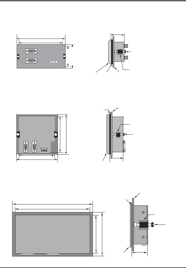
Panel Mounting
This section presents the dimensional sketches and panel cutouts for NTXS models. (All dimensions are in mm. Not to Scale.)
20
Hardware
NT2S-SF121B-EV2, NT2S-SF122B-EV2 and NT2S-SF123B-EV2
Panel cutout: 92.00 mm x 45.00 mm
All Dimensions are in mm.
108.30 |
91.20 |
|
|
|
|
|
|
44.18 |
60.50 |
|
|
|
|
|
|
||
|
|
|
|
|
|
||
|
|
|
|
|
|
|
|
|
|
|
|
|
|
|
|
|
|
|
|
|
|
|
|
27.10
|
|
|
Mounting |
|
|
234567 |
Screw |
|
|
|
|
|
|
|
Clamp |
Bezel |
Gasket |
Panel |
|
|
|
NT2S-SF125B-E, NT2S-SF126B-E and NT2S-SF127B-E
Panel Cutout: 92.00 mm x 92.00 mm
All Dimensions are in mm.
|
Gasket |
Panel |
|
|
|
|
|
|
|
||
|
|
|
|
Clamp |
|
91.30 |
106.88 |
|
1234 |
Mounting |
|
|
Screw |
|
|||
|
|
|
|
|
|
2-4 |
|
|
|
|
|
91.30 |
|
|
|
|
|
106.88 |
Bezel |
25.80 |
|
|
|
|
|
|
|
||
NT3S-ST121B-E, NT3S-ST123B-E, NT3S-ST124B-E and NT3S-ST126B-E |
|
||||
Panel cutout: 132.00 mm x 69.00 mm |
|
|
|
|
|
All Dimensions are in mm. |
|
|
|
Panel |
|
|
|
|
|
|
|
|
|
|
Gasket |
|
|
140.00 |
|
|
|
|
|
131.00 |
|
|
|
|
|
|
|
|
|
|
Mounting |
|
|
|
|
|
Clamp |
|
|
|
|
1234567890 |
Mounting |
|
|
|
|
|
Screw |
|
68.00 |
77.20 |
|
|
|
|
|
|
Bezel |
31.80 |
|
|
|
|
|
|
|
21

Hardware
2.3Power Requirements
Supply voltage requirements for NTXS series models is as follows:
NT2S-SF121B-EV2 NT2S-SF122B-EV2 NT2S-SF123B-EV2
NT2S-SF125B-E NT2S-SF126B-E NT2S-SF127B-E
NT3S-ST121B-E NT3S-ST123B-E NT3S-ST124B-E NT3S-ST126B-E
+24VDC + 10%, 1.5W maximum on Power Port +5VDC + 10% on PLC port
+5VDC + 10% on PLC port
+24VDC + 10%, 1.5W maximum on Power Port +5VDC + 10% on PLC port
+5VDC + 10% on PLC port
+24VDC + 10%, 3.5W maximum on Power Port +24VDC + 10%, 3.5W maximum on Power Port +24VDC + 10%, 3.5W maximum on Power Port +24VDC + 10%, 3.5W maximum on Power Port
Please follow the instructions given below while making power supply connections for models:
1.Follow the wiring diagram on the sticker of the unit which shows terminals.
2.To make a connection strip about 7mm of insulation of the wire, turn the connector screw counter-clock wise until the gap is wide open. Insert the wire all the way in and turn the screw clockwise until it is tight.
3.Wire lengths should be minimum. Wires should run in pairs with a neutral or common paired with a live or signal wire.
4.NTXS +24VDC model is fused internally with a self resetting 60V, 400mA fuse. It is recom mended that all input power lines be protected from product failure by a fuse or breaker.
5.Adequate strain relief must be provided for the power connector, to ensure that vibration does not cause the power connector to be pulled out.
6.All the NTXS products are housed in a moulded ABS plastic case which eliminates any electrical shock hazard. Hence Safety Earth is not required to be connected to the chassis of the unit.
7.The DC ground is not directly coupled to Earth ground internally. The unit is designed to operate properly whether or not the DC ground is connected to the Earth ground. We do recom mend, however, that if the DC ground has to be connected to the Earth ground, the Earth connection should be made to a central star point as poor site earths can introduce noise into a system.
8.Do not power unit and inductive loads with the same power supply even though there is enough immunity in the NTXS to withstand the transients present on these lines. Avoid using power supplies with large capacitive outputs which may cause problems if power is cycled within a short time period.
9.If wiring is to be exposed to lightening or surges, use appropriate surge suppression devices.
10.Keep AC, high energy and rapidly switching DC wiring separate from signal wires.
11.Connecting high voltages or AC power mains to the DC input will make unit unusable and may create an electrical shock hazard to personnel. Such a failure or shock could result in serious personal injury, loss of life and/or equipment damage. DC voltage sources should provide proper isolation from main AC power and similar hazards.
22

Hardware
2.4Wiring Diagram
If wiring is to be exposed to lightening or surges, use appropriate surge suppression devices. Keep AC, high energy and rapidly switching DC wiring separate from signal wires.
Connecting high voltages or AC power mains to the DC input will make unit unusable and may create an electrical shock hazard to personnel. Such a failure or shock could result in serious personal injury, loss of life and/or equipment damage. DC voltage sources should provide proper isolation from main AC power and similar hazards.
Pin description of the power connector for NTXS Models is as follows:
|
|
|
|
|
|
|
|
|
|
|
|
1 |
2 |
3 |
|
||||||||
|
|
|
|
|
|
|
|
|
|
|
|
|
|
|
|
|
|
|
|
|
|
|
|
|
|
|
|
|
|
|
|
|
|
|
|
|
|
|
|
|
|
|
|
|
|
|
|
|
|
|
|
|
|
|
|
|
|
|
|
|
|
|
|
|
|
|
|
|
|
|
|
|
|
|
|
|
|
|
|
|
|
|
|
|
|
|
|
|
|
|
|
|
|
|
|
DC+ DCEarth 24Vdc
2.5Communication Ports
NTXS unit has 2 types of communication ports.
One port of NT2S models has RS232/CMOS signals. This port is used to connect to PLC. The other port has RS232 signals which is used for receiving configuration setup and printing.
Note: NT2S-SF123B-EV2 and NT2S-SF127B-E units have only a PLC port with CMOS signals.
NT3S has multi-signal ports meaning RS232/RS485/CMOS signal level ports.
Note: NT3S-ST126B-E unit has only RS232 and CMOS signal level ports.
NT3S units can simultaneously communicate with two devices on these serial ports. Units can receive data from PC on either of the ports. Both the ports are also capable of Serial Printing. Each port has to be configured for their function. Even if both the ports are configured for PLC connection, user can download data from NTXS software on either of the ports. For Programming cable details, please refer to Appendix.
Different cables are required for different devices. Cable details for any particular device are given in the Operation Manual of that device. Pin description of the communication Ports for NT2S and NT3S models is as given in following pages.
23

Hardware
NT3S-ST121B-E
Com1 and Com2 Ports
Port Type: DB9 Female
|
|
Pin |
|
|
Name |
|
Description |
|
|
|
|
Number |
|
|
|
|
|
|
|
|
1 |
|
|
TX+ |
|
Transmit + |
|
|
|
|
|
|
|
|
|
|
|
|
|
|
2 |
|
|
232TXD |
|
Transmit 232 |
|
||
|
|
|
|
|
|
|
|
|
|
|
3 |
|
|
RXD |
|
Receive 232 / CMOS |
|
||
|
|
|
|
|
|
|
|
|
|
|
4 |
|
|
RX+ |
|
Receive + |
|
|
|
|
|
|
|
|
|
|
|
|
|
|
5 |
|
|
GND |
|
Circuit Ground |
|
||
|
|
|
|
|
|
|
|
|
|
|
6 |
|
|
VCC |
|
+5 VDC |
|
||
|
|
|
|
|
|
|
|
|
|
|
7 |
|
|
CMOSTXD |
|
Transmit CMOS |
|
||
|
|
|
|
|
|
|
|
|
|
|
8 |
|
|
TX- |
|
Transmit - |
|
||
|
|
|
|
|
|
|
|
|
|
|
9 |
|
|
RX- |
|
Receive - |
|
||
|
|
|
|
|
|
|
|
|
|
NT3S-ST123B-E / NT3S-ST124B-E |
|
|
|
|
|||||
Com1 Port |
|
|
|
|
|
||||
Port Type: DB9 Female |
|
|
|
|
|
||||
|
|
|
|
|
|
|
|
||
|
|
Pin |
|
Name |
|
Description |
|
||
|
|
Number |
|
|
|
|
|
|
|
|
|
|
|
|
|
|
|
||
|
|
1 |
|
|
TX+ |
|
Transmit + |
|
|
|
|
|
|
|
|
|
|
||
|
|
2 |
|
|
232TXD |
|
Transmit 232 |
|
|
|
|
|
|
|
|
|
|
||
|
|
3 |
|
|
RXD |
|
Receive 232 / CMOS |
|
|
|
|
|
|
|
|
|
|
||
|
|
4 |
|
|
RX+ |
|
Receive + |
|
|
|
|
|
|
|
|
|
|
||
|
|
5 |
|
|
GND |
|
Circuit Ground |
|
|
|
|
|
|
|
|
|
|
||
|
|
6 |
|
|
VCC |
|
+5 VDC |
|
|
|
|
|
|
|
|
|
|
||
|
|
7 |
|
|
CMOSTXD |
|
Transmit CMOS |
|
|
|
|
|
|
|
|
|
|
||
|
|
8 |
|
|
TX- |
|
Transmit - |
|
|
|
|
|
|
|
|
|
|
||
|
|
9 |
|
|
RX- |
|
Receive - |
|
|
|
|
|
|
|
|
|
|
|
|
24
Loading...