


 Loading...
Omron TJ1-PRT, TJ1-MC16, TJ1-ML04, GRT1-ML2, TJ1-FL02 REFERENCE MANUAL
...
Cat. No.
I51E-EN-05
Trajexia motion control system
TJ1-MC04, TJ1-MC16, TJ1-ML04, TJ1-ML16, TJ1-PRT, TJ1-DRT, TJ1-CORT, TJ1-FL02 GRT1-ML2
hardware reference manual

Notice
OMRON products are manufactured for use according to proper procedures by a qualified operator and only for the purposes described in this manual. The following conventions are used to indicate and classify precautions in this manual. Always heed the information provided with them. Failure to heed precautions can result in injury to people or damage to property.
Definition of precautionary information
WARNING
Indicates a potentially hazardous situation, which, if not avoided, could result in death or serious injury.
Caution
Indicates a potentially hazardous situation, which, if not avoided, may result in minor or moderate injury, or property damage.
Trademarks and Copyrights
PROFIBUS is a registered trademark of PROFIBUS International. MECHATROLINK is a registered trademark of Yaskawa Corporation. DeviceNet is a registered trademark of Open DeviceNet Vendor Assoc INC. CIP is a registered trademark of Open DeviceNet Vendor Assoc INC. CANopen is a registered trademark of CAN in Automation (CiA). ModbusTCP is a registered trademark of Modbus IDA.
Trajexia is a registered trademark of OMRON.
Motion Perfect is a registered trademark of Trio Motion Technology Ltd. All other product names, company names, logos or other designations mentioned herein are trademarks of their respective owners.
0.5 Revision
© OMRON, 2010
All rights reserved. No part of this publication may be reproduced, stored in a retrieval system, or transmitted, in any form, or by any means, mechanical, electronic, photocopying, recording, or otherwise, without the prior written permission of OMRON.
No patent liability is assumed with respect to the use of the information contained herein. Moreover, because OMRON is constantly striving to improve its high-quality products, the information contained in this manual is subject to change without notice. Every precaution has been taken in the preparation of this manual. Nevertheless, OMRON assumes no responsibility for errors or omissions. Neither is any liability assumed for damages resulting from the use of the information contained in this publication.
HARDWARE REFERENCE MANUAL |
I |

About this manual
This manual describes the installation and operation of the Trajexia Motion Control System.
Please read this manual and the related manuals listed in the following table carefully and be sure you understand the information provided before attempting to install or operate the Trajexia Motion Control units. Be sure to read the precautions provided in the following section.
|
Name |
Cat. No. |
Contents |
|
|
|
|
|
Trajexia motion con- |
I50E |
Describes how to get quickly familiar |
|
trol system |
|
with Trajexia, moving a single axis using |
|
QUICK START |
|
MECHATROLINK-II, in a test set-up. |
|
GUIDE |
|
|
|
|
|
|
|
Trajexia motion con- |
I51E |
Describes the installation and hardware |
|
trol system HARD- |
|
specification of the Trajexia units, and |
|
WARE |
|
explains the Trajexia system philosophy. |
|
REFERENCE MAN- |
|
|
|
UAL |
|
|
|
|
|
|
|
Trajexia motion con- |
I52E |
Describes the BASIC commands to be |
|
trol system |
|
used for programming Trajexia, commu- |
|
PROGRAMMING |
|
nication protocols and Trajexia Studio |
|
MANUAL |
|
software, gives practical examples and |
|
|
|
troubleshooting information. |
|
|
|
|
|
Sigma-II Servo |
SIEP S800000 15 |
Describes the installation and operation |
|
Driver manual |
|
of Sigma-II Servo Drivers |
|
|
|
|
|
Sigma-III with |
SIEP S800000 11 |
Describes the installation and operation |
|
MECHATROLINK |
|
of Sigma-III Servo Drivers with MECHA- |
|
interface manual |
|
TROLINK-II interface |
|
|
|
|
|
Sigma-V Servo |
SIEP S800000-44-O-OY |
Describes the installation and operation |
|
Driver manual |
SIEP S800000-46-O-OY |
of Sigma-V Servo Drivers |
|
|
SIEP S800000-48-O-OY |
|
|
|
|
|
0.5Revision |
JUNMA series servo |
TOEP-C71080603 01-OY |
Describes the installation and operation |
drive manual |
|
of JUNMA Servo Drivers |
|
|
|
||
|
|
|
|
Name |
Cat. No. |
Contents |
|
|
|
V7 Inverter |
TOEP C71060605 02-OY |
Describes the installation and operation |
|
|
of V7 Inverters |
|
|
|
F7Z Inverter |
TOE S616-55 1-OY |
Describes the installation and operation |
|
|
of F7Z Inverters |
|
|
|
G7 Inverter |
TOE S616-60 |
Describes the installation and operation |
|
|
of G7 Inverters |
|
|
|
JUSP-NS115 man- |
SIEP C71080001 |
Describes the installation and operation |
ual |
|
of the MECHATROLINK-II application |
|
|
module |
|
|
|
SI-T MECHATRO- |
SIBP-C730600-08 |
Describes the installation and operation |
LINK interface for |
|
of MECHATROLINK-II interfaces for G7 |
the G7 & F7 |
|
and F7 Inverters |
|
|
|
ST-T/V7 MECHA- |
SIBP-C730600-03 |
Describes the installation and operation |
TROLINK interface |
|
of MECHATROLINK-II interfaces for V7 |
for the V7 |
|
Inverters |
|
|
|
MECHATROLINK IO |
SIE C887-5 |
Describes the installation and operation |
Modules |
|
of MECHATROLINK-II input and output |
|
|
modules and the MECHATROLINK-II |
|
|
repeater |
|
|
|
SYSMAC CS/CJ |
W342 |
Describes FINS communications proto- |
Series Communica- |
|
col and FINS commands |
tions Commands |
|
|
|
|
|
Omron Smartslice |
W455-E1 |
Describes the installation and operation |
GRT1-Series, slice I/ |
|
of Omron slice I/O units |
O units, Operation |
|
|
manual |
|
|
|
|
|
Omron G-series |
I566-E1 |
Describes the installation and operation |
user’s manual |
|
of G-series Servo Drivers |
|
|
|
Omron Accurax G5 |
I572-E1 |
Describes the installation and operation |
user’s manual |
|
of Accurax G5 Servo Drivers |
|
|
|
Trajexia Studio user |
I56E-EN |
Describes the use of Trajexia Studio |
manual |
|
programming software |
|
|
|
HARDWARE REFERENCE MANUAL |
II |

WARNING
Failure to read and understand the information provided in this manual may result in personal injury or death, damage to the product, or product failure. Please read each section in its entirety and be sure you understand the information provided in the section and related sections before attempting any of the procedures or operations given.
Functions supported by unit versions
During the development of Trajexia new functionality was added to the controller unit after market release.
This functionality is implemented in the firmware, and/or the FPGA of the controller unit.
In the table below, the overview of the applicable functionality is shown related to the firmware and FPGA version of the TJ1-MC__.
|
Functionality |
TJ1-MC__ Firmware |
TJ1-MC__ FPGA |
|
|
version |
version |
|
|
|
|
|
Full support TJ1-FL02 |
V1.6509 |
21 and higher |
|
|
|
|
|
Support BASIC commands FINS_COMMS |
V1.6509 |
All versions |
|
|
|
|
|
Support TJ1-DRT |
V1.6509 |
All versions |
|
|
|
|
|
Support TJ1-MC04 andTJ1-ML04 |
V1.6607 |
21 and higher |
|
|
|
|
|
Support TJ1-CORT, GRT1-ML2, Mod- |
V1.6652 |
21 and higher |
|
busTCP, Sigma-V series Servo Drivers |
|
|
|
(except DATUM and REGIST BASIC com- |
|
|
|
mands) and allow Inverters to be controlled |
|
|
|
as servo axes |
|
|
|
|
|
|
|
Support for G-series Drivers, full support for |
V1.6714 |
21 and higher |
|
Sigma-V series Servo Drivers |
|
|
|
|
|
|
0.5Revision |
Support for Accurax G5 Drivers |
V1.6720 |
21 and higher |
|
|
|
|
Verify the firmware and FPGA versions of the TJ1-MC__ |
|
||
|
|
||
Connect the TJ1-MC__ to Trajexia Studio software. Refer to the Programming Manual.
Open the terminal window and type the following commands:
Type PRINT VERSION in the terminal window. The version parameter returns the current firmware version number of the motion controller.
Type PRINT FPGA_VERSION SLOT(-1) in the terminal window. The parameter returns the current FPGA version number of the TJ1-MC__.
HARDWARE REFERENCE MANUAL |
III |

Contents
1 Safety warnings and precautions................................................................................................................................................................ |
1 |
|
1.1 |
Intended audience ............................................................................................................................................................................................................................ |
1 |
1.2 |
General precautions ......................................................................................................................................................................................................................... |
1 |
1.3 |
Safety precautions ............................................................................................................................................................................................................................ |
1 |
1.4 |
Operating environment precautions.................................................................................................................................................................................................. |
2 |
1.5 |
Application precautions..................................................................................................................................................................................................................... |
3 |
1.6 |
Unit assembly precautions................................................................................................................................................................................................................ |
5 |
1.7 |
Conformance to EC Directives Conformance................................................................................................................................................................................... |
6 |
2 System philosophy....................................................................................................................................................................................... |
7 |
|
2.1 |
Introduction ....................................................................................................................................................................................................................................... |
7 |
2.2 |
Motion control concepts.................................................................................................................................................................................................................... |
8 |
2.3 |
Servo system principles.................................................................................................................................................................................................................. |
19 |
2.4 |
Trajexia system architecture ......................................................................................................................................................................................................... |
22 |
2.5 |
Cycle time ...................................................................................................................................................................................................................................... |
23 |
2.6 |
Program control and multi-tasking .................................................................................................................................................................................................. |
29 |
2.7 |
Motion sequence and axes............................................................................................................................................................................................................. |
30 |
2.8 |
Motion buffers ............................................................................................................................................................................................................................... |
40 |
2.9 |
Mechanical system ......................................................................................................................................................................................................................... |
42 |
3 |
Hardware reference .................................................................................................................................................................................... |
43 |
|
|
3.1 |
Introduction ..................................................................................................................................................................................................................................... |
43 |
|
3.2 |
All units .......................................................................................................................................................................................................................................... |
46 |
|
3.3 |
Power Supply Unit (PSU) ............................................................................................................................................................................................................... |
57 |
|
3.4 |
TJ1-MC__ ..................................................................................................................................................................................................................................... |
59 |
|
3.5 |
TJ1-ML__........................................................................................................................................................................................................................................ |
70 |
|
3.6 |
GRT1-ML2 .................................................................................................................................................................................................................................... |
143 |
|
3.7 |
TJ1-PRT ....................................................................................................................................................................................................................................... |
158 |
|
3.8 |
TJ1-DRT ....................................................................................................................................................................................................................................... |
162 |
|
3.9 |
TJ1-CORT .................................................................................................................................................................................................................................... |
166 |
|
3.10 |
TJ1-FL02 ...................................................................................................................................................................................................................................... |
170 |
A |
Differences between Sigma-II and Junma.............................................................................................................................................. |
188 |
|
Revision history .............................................................................................................................................................................................. |
189 |
||
0.5 Revision
HARDWARE REFERENCE MANUAL |
IV |
Safety warnings and precautions
1 Safety warnings and precautions
1.1Intended audience
This manual is intended for personnel with knowledge of electrical systems (electrical engineers or the equivalent) who are responsible for the design, installation and management of factory automation systems and facilities.
1.2General precautions
The user must operate the product according to the performance specifications described in this manual.
Before using the product under conditions which are not described in the manual or applying the product to nuclear control systems, railroad systems, aviation systems, vehicles, safety equipment, petrochemical plants, and other systems, machines and equipment that can have a serious influence on lives and property if used improperly, consult your OMRON representative.
1.3Safety precautions
WARNING
Do not attempt to take the Unit apart and do not touch any of the internal parts while power is being supplied.
Doing so may result in electrical shock.
WARNING
Do not touch any of the terminals or terminal blocks while power is being supplied.
Doing so may result in electric shock.
0.5 Revision
HARDWARE REFERENCE MANUAL
WARNING
Never short-circuit the positive and negative terminals of the batteries, charge the batteries, disassemble them, deform them by applying pressure, or throw them into a fire.
The batteries may explode, combust or leak liquid.
WARNING
Fail-safe measures must be taken by the customer to ensure safety in the event of incorrect, missing, or abnormal signals caused by broken signal lines, momentary power interruptions, or other causes.
Not doing so may result in serious accidents.
WARNING
Emergency stop circuits, interlock circuits, limit circuits, and similar safety measures must be provided by the customer as external circuits, i.e., not in the Trajexia motion controller.
Not doing so may result in serious accidents.
WARNING
When the 24 VDC output (I/O power supply to the TJ1) is overloaded or short-circuited, the voltage may drop and result in the outputs being turned off.As a countermeasure for such problems, external safety measures must be provided to ensure safety in the system.
WARNING
The TJ1 outputs will go off due to overload of the output transistors (protection).As a countermeasure for such problems, external safety measures must be provided to ensure safety in the system.
1
0.5 Revision
Safety warnings and precautions
WARNING |
Caution |
The TJ1 will turn off the WDOG when its self-diagnosis function |
Tighten the screws on the terminal block of the Power Supply Unit |
detects any error.As a countermeasure for such errors, external |
to the torque specified in this manual. |
safety measures must be provided to ensure safety in the system. |
Loose screws may result in burning or malfunction. |
WARNING |
1.4 |
Operating environment precautions |
|
|
|
Provide safety measures in external circuits, i.e., not in the Tra- |
|
|
jexia Motion Controller (referred to as "TJ1"), in order to ensure |
|
Caution |
safety in the system if an abnormality occurs due to malfunction of |
|
|
|
Do not operate the Unit in any of the following locations. |
|
the TJ1 or another external factor affecting the TJ1 operation. |
|
|
|
Doing so may result in malfunction, electric shock, or burning. |
|
Not doing so may result in serious accidents. |
|
|
|
- Locations subject to direct sunlight. |
|
|
|
|
|
|
- Locations subject to temperatures or humidity outside the |
WARNING |
|
range specified in the specifications. |
|
- Locations subject to condensation as the result of severe |
|
Do not attempt to disassemble, repair, or modify any Units. |
|
|
|
changes in temperature. |
|
Any attempt to do so may result in malfunction, fire, or electric |
|
|
|
- Locations subject to corrosive or flammable gases. |
|
shock. |
|
|
|
- Locations subject to dust (especially iron dust) or salts. |
|
|
|
|
|
|
- Locations subject to exposure to water, oil, or chemicals. |
Caution |
|
- Locations subject to shock or vibration. |
Confirm safety at the destination unit before transferring a program |
|
|
to another unit or editing the memory. |
|
Caution |
Doing either of these without confirming safety may result in injury. |
|
|
|
|
Take appropriate and sufficient countermeasures when installing |
|
|
systems in the following locations. |
Caution |
|
Inappropriate and insufficient measures may result in malfunction. |
User programs written to the Motion Control Unit will not be auto- |
|
- Locations subject to static electricity or other forms of noise. |
matically backed up in the TJ1 flash memory (flash memory func- |
|
- Locations subject to strong electromagnetic fields. |
tion). |
|
- Locations subject to possible exposure to radioactivity. |
|
|
- Locations close to power supplies. |
Caution
Pay careful attention to the polarity (+/-) when wiring the DC power supply.A wrong connection may cause malfunction of the system.
HARDWARE REFERENCE MANUAL |
2 |
Safety warnings and precautions
Caution
The operating environment of the TJ1 System can have a large effect on the longevity and reliability of the system.
Improper operating environments can lead to malfunction, failure, and other unforeseeable problems with the TJ1 System.
Make sure that the operating environment is within the specified conditions at installation and remains within the specified conditions during the life of the system.
1.5Application precautions
WARNING
Do not start the system until you check that the axes are present and of the correct type.
The numbers of the Flexible axes will change if MECHATROLINKII network errors occur during start-up or if the MECHATROLINK-II network configuration changes.
Not doing so may result in unexpected operation.
WARNING
Check the user program for proper execution before actually running it in the Unit.
Not checking the program may result in an unexpected operation.
Caution
Always use the power supply voltage specified in this manual. An incorrect voltage may result in malfunction or burning.
0.5 Revision
HARDWARE REFERENCE MANUAL
Caution
Take appropriate measures to ensure that the specified power with the rated voltage and frequency is supplied. Be particularly careful in places where the power supply is unstable.
An incorrect power supply may result in malfunction.
Caution
Install external breakers and take other safety measures against short-circuiting in external wiring.
Insufficient safety measures against short-circuiting may result in burning.
Caution
Do not apply voltage to the Input Units in excess of the rated input voltage.
Excess voltage may result in burning.
Caution
Do not apply voltage or connect loads to the Output Units in excess of the maximum switching capacity.
Excess voltage or loads may result in burning.
Caution
Disconnect the functional ground terminal when performing withstand voltage tests.
Not disconnecting the functional ground terminal may result in burning.
Caution
Always connect to a class-3 ground (to 100Ω or less) when installing the Units.
Not connecting to a class-3 ground may result in electric shock.
3
0.5 Revision
Safety warnings and precautions
Caution
Always turn off the power supply to the system before attempting any of the following.
Not turning off the power supply may result in malfunction or electric shock.
-Mounting or dismounting expansion Units, CPU Units, or any other Units.
-Assembling the Units.
-Setting dipswitches or rotary switches.
-Connecting or wiring the cables.
-Connecting or disconnecting the connectors.
Caution
Be sure that all mounting screws, terminal screws, and cable connector screws are tightened to the torque specified in this manual. Incorrect tightening torque may result in malfunction.
Caution
Leave the dust protective label attached to the Unit when wiring. Removing the dust protective label may result in malfunction.
Caution
Remove the dust protective label after the completion of wiring to ensure proper heat dissipation.
Leaving the dust protective label attached may result in malfunction.
Caution
Use crimp terminals for wiring. Do not connect bare stranded wires directly to terminals.
Connection of bare stranded wires may result in burning.
HARDWARE REFERENCE MANUAL
Caution
Double-check all the wiring before turning on the power supply. Incorrect wiring may result in burning.
Caution
Wire correctly.
Incorrect wiring may result in burning.
Caution
Mount the Unit only after checking the terminal block completely.
Caution
Be sure that the terminal blocks, expansion cables, and other items with locking devices are properly locked into place. Improper locking may result in malfunction.
Caution
Confirm that no adverse effect will occur in the system before changing the operating mode of the system.
Not doing so may result in an unexpected operation.
Caution
Resume operation only after transferring to the new CPU Unit the contents of the VR and table memory required for operation.
Not doing so may result in an unexpected operation.
Caution
When replacing parts, be sure to confirm that the rating of a new part is correct.
Not doing so may result in malfunction or burning.
4
0.5 Revision
Safety warnings and precautions
Caution |
|
Caution |
Do not pull on the cables or bend the cables beyond their natural |
|
The TJ1 will start operating in RUN mode when the power is |
limit. Doing so may break the cables. |
|
turned on and if a BASIC program is set to Auto Run mode. |
Caution |
|
Caution |
Before touching the system, be sure to first touch a grounded |
|
Always check the “Status-Words” of each GRT1-ML2 coupler. |
metallic object in order to discharge any static build-up. |
|
Not doing so can lead to missing or incorrect I/O data. |
Otherwise it might result in a malfunction or damage. |
|
|
|
|
Caution |
Caution |
|
Always check the status of the connected MECHATROLINK-II |
UTP cables are not shielded. In environments that are subject to |
|
devices in a BASIC program. |
noise use a system with shielded twisted-pair (STP) cable and |
|
Not doing so may result in an unexpected operation. |
hubs suitable for an FA environment. |
|
|
Do not install twisted-pair cables with high-voltage lines. |
|
Caution |
Do not install twisted-pair cables near devices that generate noise. |
|
|
Do not install twisted-pair cables in locations that are subject to |
|
The TJ1-CORT unit is developed to exchange I/O data between |
high humidity. |
|
the Trajexia system and a CANopen network. |
Do not install twisted-pair cables in locations subject to excessive |
|
The TJ1-CORT is not able to exchange motion commands. |
dirt and dust or to oil mist or other contaminants. |
|
Using the TJ1-CORT to exchange motion commands may result in |
|
|
unexpected operation. |
Caution |
1.6 |
Unit assembly precautions |
Use the dedicated connecting cables specified in operation manu- |
|
|
als to connect the Units. |
|
|
Using commercially available RS-232C computer cables may |
|
Caution |
cause failures in external devices or the Motion Control Unit. |
|
Install the unit properly. |
|
|
Improper installation of the unit may result in malfunction. |
Caution |
|
|
Outputs may remain on due to a malfunction in the built-in transis- |
|
Caution |
tor outputs or other internal circuits. |
|
Be sure to mount the TJ1-TER supplied with the TJ1-MC__ to the |
As a countermeasure for such problems, external safety measures |
|
right most Unit. |
must be provided to ensure the safety of the system. |
|
Unless the TJ1-TER is properly mounted, the TJ1 will not function |
|
|
properly. |
|
|
|
HARDWARE REFERENCE MANUAL |
|
5 |
Safety warnings and precautions
1.7Conformance to EC Directives Conformance
1.7.1Concepts
The concepts for the directives EMC and Low Voltage are as follows:
EMC Directives
OMRON devices that comply with EC Directives also conform to the related EMC standards so that they can be more easily built into other devices or machines. The actual products have been checked for conformity to EMC standards. Whether the products conform to the standards in the system used by the customer, however, must be checked by the customer. EMC-related performance of the OMRON devices that comply with EC Directives will vary depending on the configuration, wiring, and other conditions of the equipment or control panel in which the OMRON devices are installed. The customer must, therefore, perform final checks to confirm that devices and the over-all machine conform to EMC standards.
Low Voltage Directive
Always ensure that devices operating at voltages of 50 to 1,000 VAC or 75 to 1,500 VDC meet the required safety standards.
1.7.2Conformance to EC Directives
The Trajexia Motion Controllers comply with EC Directives.
To ensure that the machine or device in which a system is used complies with EC directives, the system must be installed as follows:
1.The system must be installed within a control panel.
2.Reinforced insulation or double insulation must be used for the DC power supplies used for the communications and I/O power supplies.
0.5 Revision
HARDWARE REFERENCE MANUAL |
6 |
0.5 Revision
System philosophy
2 System philosophy
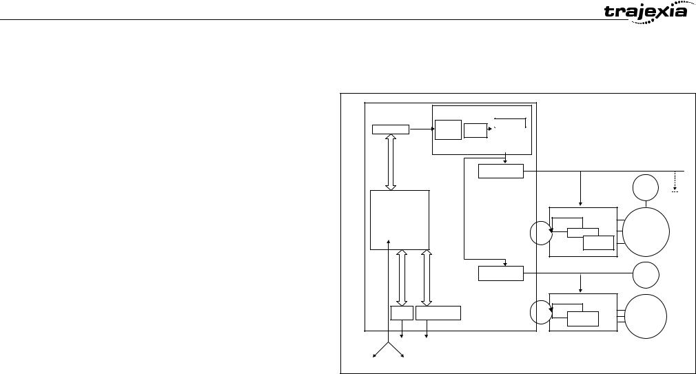
2.1Introduction
The system philosophy is centred around the relationship between: |
fig. 1 |
• |
System architecture |
TJ1-MC__ |
|
|
|||
• |
Cycle time |
AXIS CONTROL LOOP |
|
||||
• Program control and multi-tasking |
|
|
|
Positioniti |
|
||
|
|
|
|
|
Bufferff & |
AXIS TYPETYPE |
|
• Motion sequence and axes |
Program Buffer |
profilefile |
Loop |
|
|||
|
|
gereratort |
|
||||
|
|
|
|
|
|
|
|
• |
Motion buffers |
|
|
|
|
|
|
A clear understanding of the relationship between these concepts is |
|
|
|
TJ1-ML__ |
|
||
necessary to obtain the best results for the Trajexia system. |
|
|
|
|
ENC |
||
|
|
|
BASIC PROGRAMS |
|
All other |
||
2.1.1 |
Glossary |
Process 2 |
|
|
Servo Driver |
||
|
|
Drivers |
|||||
|
|
|
Process 1 |
|
|
|
Servo |
|
|
|
|
|
|
|
|
|
|
|
Process 3 |
|
|
PositionPosition |
|
|
|
|
|
|
|
|
|
Motion sequence |
… |
|
|
LoopLoop |
MOTOR |
||
Process 14 |
|
SpeedSpeed LoopLoop |
|||||
|
|
|
|
|
|
||
The Motion Sequence is responsible for controlling the position of the axes. |
Comms |
|
|
TorqueTorque |
|
||
|
|
LoopLoop |
|
||||
|
|
|
|
|
|
||
|
|
|
|
|
|
|
|
Servo period |
|
|
|
TJ1-FL02 |
ENC |
||
Defines the frequency at which the Motion Sequence is executed. The servo |
MC I/O |
|
|
|
|
||
period must be set according to the configuration of the physical axes. The |
|
|
|
Servo Driver |
|
||
available settings are 0.5ms, 1ms or 2ms. |
|
|
|
|
|||
Ethernet |
TJ1-PRT |
Speed Loop |
MOTOR |
||||
|
|
|
|
FINS |
Torque |
||
Cycle time |
|
|
|
Loop |
|
||
|
|
|
|
|
|||
Is the time needed to execute one complete cycle of operations in the TJ1- |
Ethernet |
Profibus |
|
|
|||
|
|
|
|
|
|||
MC__. The cycle time is divided in 4 time slices of equal time length, called |
BUILT-IN |
Via |
|
|
|
||
"CPU Tasks". The cycle time is 1ms if SERVO_PERIOD=0.5ms or |
TJ1-ML16 |
|
|
||||
|
|
|
|
|
|||
SERVO_PERIOD=1ms and 2ms if the SERVO_PERIOD=2ms. |
|
|
|
|
|
||
CPU tasks
The operations executed in each CPU task are:
CPU task |
Operation |
|
|
|
|
First CPU task |
Motion Sequence |
|
|
Low priority process |
|
|
|
|
|
|
|
HARDWARE REFERENCE MANUAL |
7 |
|

System philosophy
0.5 Revision
CPU task |
Operation |
|
|
Second CPU task |
High priority process |
|
|
Third CPU task |
Motion Sequence (only if SERVO_PERIOD=0.5ms) |
|
LED Update |
|
High priority process |
|
|
Fourth CPU task |
External Communications |
|
|
Program
A program is a piece of BASIC code.
Process
Is a program in execution with a certain priority assigned. Process 0 to 12 are Low priority processes and Process 13 and 14 are High priority processes. First the process priority, High or Low, and then the process number, from high to low, will define to which CPU task the process will be assigned.
2.2Motion control concepts
The TJ1-MC__ offers these types of positioning control operations:
1.Point-to-Point (PTP) control
2.Continuous Path (CP) control
3.Electronic Gearing (EG) control.
This section introduces some of the commands and parameters used in the
BASIC programming of the motion control application.
Coordinate system
Positioning operations performed by the TJ1-MC__ are based on an axis coordinate system. The TJ1-MC__ converts the position data from either the connected Servo Driver or the connected encoder into an internal absolute coordinate system.
The engineering unit that specifies the distances of travelling can be freely defined for each axis separately. The conversion is performed through the use of the unit conversion factor, which is defined by the UNITS axis
HARDWARE REFERENCE MANUAL |
8 |
System philosophy
parameter. The origin point of the coordinate system can be determined using the DEFPOS command. This command re-defines the current position to zero or any other value.
A move is defined in either absolute or relative terms. An absolute move takes the axis (A) to a specific predefined position with respect to the origin point. A relative move takes the axis from the current position to a position that is defined relative to this current position. The figure shows an example of relative (command MOVE) and absolute (command MOVEABS) linear moves.
fig. 2
|
MOVEABS(30) |
|
|
MOVE(60) |
|
|
MOVEABS(50) |
|
|
MOVE(50) |
|
|
MOVE(30) |
|
0 |
50 |
A |
100 |
2.2.1PTP control
In point-to-point positioning, each axis is moved independently of the other axis. The TJ1-MC__ supports the following operations:
•Relative move
•Absolute move
•Continuous move forward
•Continuous move reverse.
0.5 Revision
HARDWARE REFERENCE MANUAL |
9 |
System philosophy
Relative and absolute moves
To move a single axis either the command MOVE for a relative move or the command MOVEABS for an absolute move is used. Each axis has its own move characteristics, which are defined by the axis parameters.
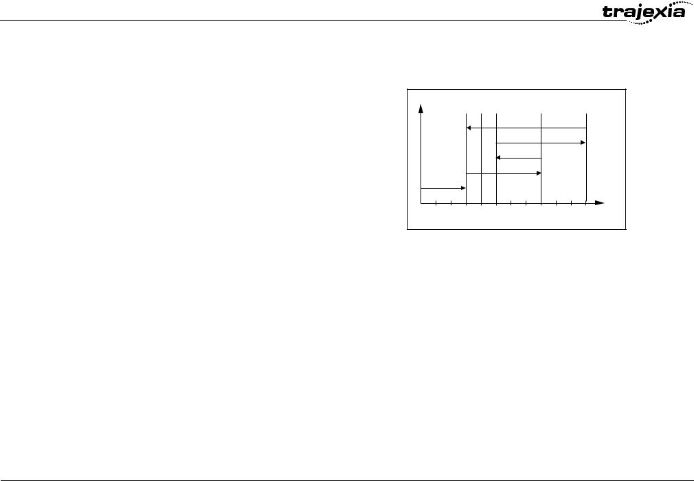
Suppose a control program is executed to move from the origin to an axis no. 0 (A) coordinate of 100 and axis no. 1 (B) coordinate of 50. If the speed parameter is set to be the same for both axes and the acceleration and deceleration rate are set sufficiently high, the movements for axis 0 and axis 1 will be as shown in the figure.
At start, both the axis 0 and axis 1 moves to a coordinate of 50 over the same duration of time. At this point, axis 1 stops and axis 0 continues to move to a coordinate of 100.
The move of a certain axis is determined by the axis parameters. Some relevant parameters are:
Parameter |
Description |
UNITS |
Unit conversion factor |
ACCEL |
Acceleration rate of an axis in units/s2 |
DECEL |
Deceleration rate of an axis in units/s2 |
SPEED |
Demand speed of an axis in units/s2 |
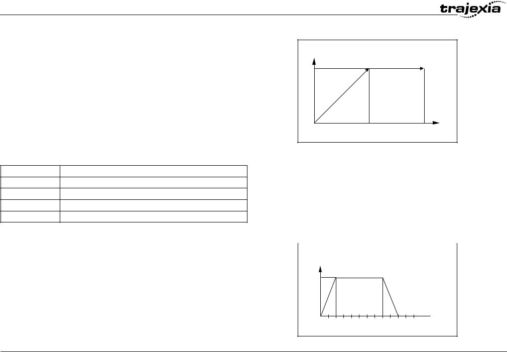
Defining moves
The speed profile in this figure shows a simple MOVE operation. Axis A is the time, axis B is the speed. The UNITS parameter for this axis has been defined for example as meters. The required maximum speed has been set to 10 m/s. In order to reach this speed in one second and also to decelerate to zero speed again in one second, both the acceleration as the deceleration rate have been set to 10 m/s2. The total distance travelled is the sum of distances travelled during the acceleration, constant speed and deceleration segments. Suppose the distance moved by the MOVE command is 40 m, the speed profile is given by the figure.
0.5 Revision
HARDWARE REFERENCE MANUAL
fig. 3
B |
|
MOVEABS(100) AXIS(0) |
|
|
|
MOVEABS(50) AXIS(1) |
|
50 |
|
|
|
0 |
50 |
100 |
A |
|
|||
|
fig. 4 |
|
B |
|
ACCEL=10 |
10 |
DECEL=10 |
|
SPEED=10 |
|
MOVE(40) |
 A
A
0 1 2 3 4 5 6
10
System philosophy
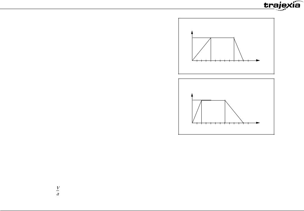
The two speed profiles in these figures show the same movement with an acceleration time respectively a deceleration time of 2 seconds. Again, Axis A is the time, axis B is the speed.
fig. 5
B |
|
|
|
|
|
|
|
|
|
|
|
|
ACCEL=5 |
10 |
|
|
|
|
|
DECEL=10 |
|
|
|
|
|
|
SPEED=10 |
|
|
|
|
|
|
MOVE(40) |
0 |
1 |
2 |
3 |
4 |
5 |
A |
6 |
fig. 6
B |
|
|
|
|
|
|
|
|
|
|
|
|
ACCEL=10 |
10 |
|
|
|
|
|
DECEL=5 |
|
|
|
|
|
|
SPEED=10 |
|
|
|
|
|
|
MOVE(40) |
0 |
1 |
2 |
3 |
4 |
5 |
A |
6 |
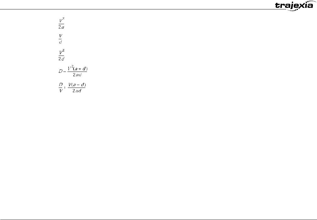
Move calculations
The following equations are used to calculate the total time for the motion of the axes.
•The moved distance for the MOVE command is D.
•The demand speed is V.
•The acceleration rate is a.
•The deceleration rate is d.
0.5 Revision
Acceleration time |
= |
HARDWARE REFERENCE MANUAL |
11 |
System philosophy
Acceleration distance |
= |
Deceleration time |
= |
Deceleration distance |
= |
Constant speed distance |
= |
Total time |
= |
0.5 Revision
Continuous moves
The FORWARD and REVERSE commands can be used to start a continuous movement with constant speed on a certain axis. The FORWARD command moves the axis in positive direction and the REVERSE command in negative direction. For these commands also the axis parameters ACCEL and SPEED apply to specify the acceleration rate and demand speed.
Both movements can be cancelled by using either the CANCEL or RAPIDSTOP command. The CANCEL command cancels the move for one axis and RAPIDSTOP cancels moves on all axes. The deceleration rate is set by DECEL.
2.2.2CP control
Continuous Path control enables to control a specified path between the start and end position of a movement for one or multiple axes. The TJ1MC__ supports the following operations:
•Linear interpolation
•Circular interpolation
•CAM control.
HARDWARE REFERENCE MANUAL |
12 |
System philosophy
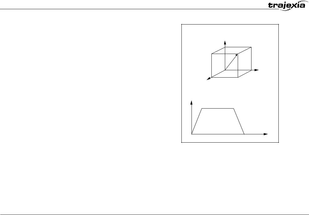
Linear interpolation
In applications it can be required for a set of motors to perform a move operation from one position to another in a straight line. Linearly interpolated moves can take place among several axes. The commands MOVE and MOVEABS are also used for the linear interpolation. In this case the commands will have multiple arguments to specify the relative or absolute move for each axis.
Consider the three axis move in a 3-dimensional plane in the figure. It corresponds to the MOVE(50,50,50) command. The speed profile of the motion along the path is given in the diagram. The three parameters SPEED, ACCEL and DECEL that determine the multi axis movement are taken from the corresponding parameters of the base axis. The MOVE command computes the various components of speed demand per axis. A is the time axis, B is the speed axis.
fig. 7
2 |
1 |
3 |
B |
A |
0.5 Revision
HARDWARE REFERENCE MANUAL |
13 |

System philosophy
Circular interpolation
It may be required that a tool travels from the starting point to the end point in an arc of a circle. In this instance the motion of two axes is related via a circular interpolated move using the MOVECIRC command.
Consider the diagram in the figure. It corresponds to the MOVECIRC(- 100,0,-50,0,0) command. The centre point and desired end point of the trajectory relative to the start point and the direction of movement are specified. The MOVECIRC command computes the radius and the angle of rotation. Like the linearly interpolated MOVE command, the ACCEL, DECEL and SPEED variables associated with the base axis determine the speed profile along the circular move.
CAM control
Additional to the standard move profiles the TJ1-MC__ also provides a way to define a position profile for the axis to move. The CAM command moves an axis according to position values stored in the TJ1-MC__ Table array.
The speed of travelling through the profile is determined by the axis parameters of the axis.
The figure corresponds to the command CAM(0,99,100,20). A is the time axis, B is the position axis.
fig. 8
|
|
50 |
-50 |
0 |
50 |
|
|
fig. 9 |
|
B |
|
|
|
A |
0.5 Revision
2.2.3EG control
Electronic Gearing control allows you to create a direct gearbox link or a linked move between two axes. The MC Unit supports the following operations.
•Electronic gearbox
•Linked CAM
•Linked move
•Adding axes
HARDWARE REFERENCE MANUAL |
14 |
System philosophy
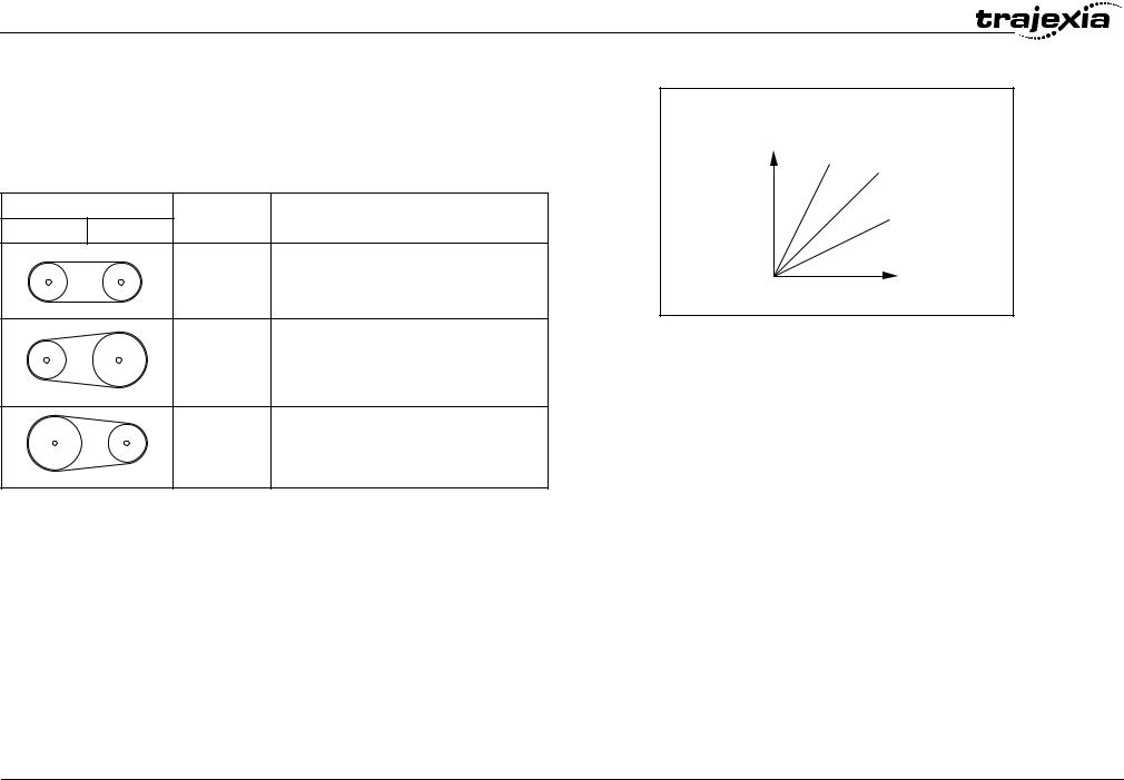
Electronic gearbox
The TJ1-MC__ is able to have a gearbox link from one axis to another as if there is a physical gearbox connecting them. This can be done using the CONNECT command in the program. In the command the ratio and the axis to link to are specified.
In the figure, A is the Master axis, and B is the CONNECT axis.
Axes |
Ratio |
CONNECT command |
0 |
1 |
|
|
1:1 |
CONNECT(1,0) AXIS(1) |
fig. 10
B |
2:1 |
1:1 |
1:2 |
A |
2:1 |
CONNECT(2,0) AXIS(1) |
1:2 |
CONNECT(0.5,0) AXIS(1) |
0.5 Revision
HARDWARE REFERENCE MANUAL |
15 |
System philosophy
Linked CAM control
Next to the standard CAM profiling tool the TJ1-MC__ also provides a tool to link the CAM profile to another axis. The command to create the link is called CAMBOX. The travelling speed through the profile is not determined by the axis parameters of the axis but by the position of the linked axis. This is like connecting two axes through a cam.
In the figure, A is the Master axis (0) position, and B is the CAMBOX Axis (1) position.
fig. 11
B
 A
A
Linked move
The MOVELINK command provides a way to link a specified move to a master axis. The move is divided into an acceleration, deceleration and constant speed part and they are specified in master link distances. This can be particularly useful for synchronizing two axes for a fixed period.
The labels in the figure are:
A.Time axis.
B.Speed axis.
C.Master axis (1).
D.Synchronized.
E.MOVELINK axis (0).
fig. 12
B |
|
C |
D |
|
E |
|
A |
0.5 Revision
HARDWARE REFERENCE MANUAL |
16 |
System philosophy
Adding axes
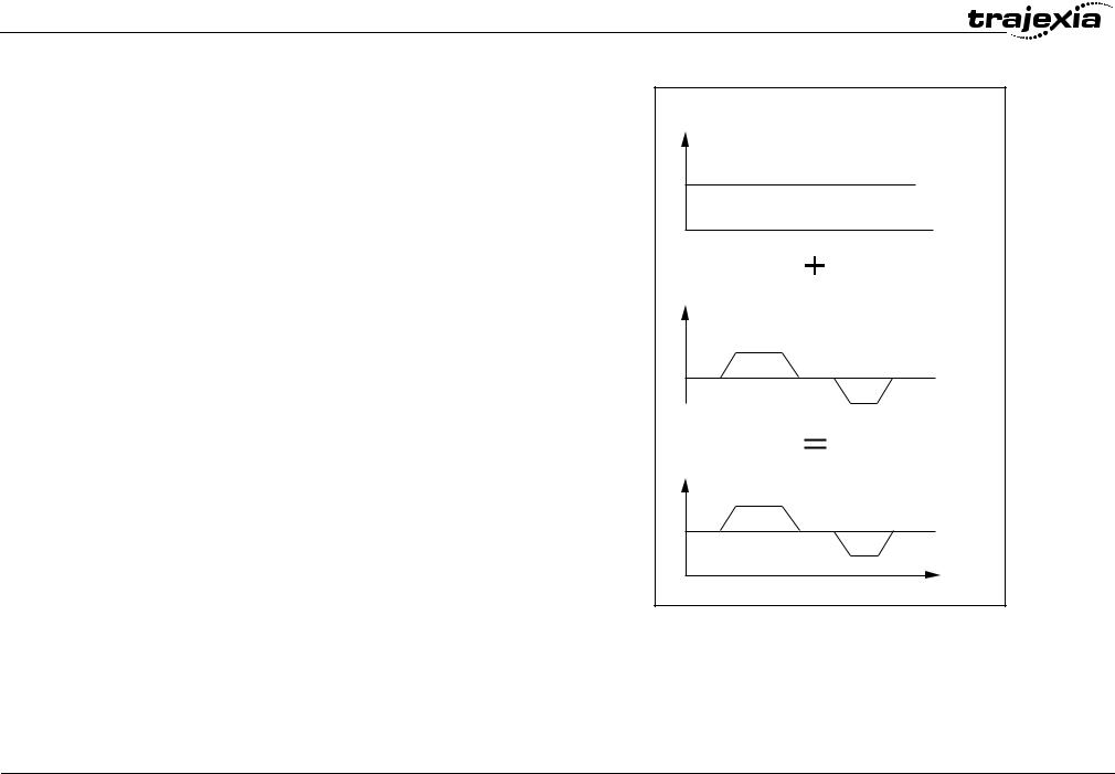
It is very useful to be able to add all movements of one axis to another. One possible application is for instance changing the offset between two axes linked by an electronic gearbox. The TJ1-MC__ provides this possibility by using the ADDAX command. The movements of the linked axis will consists of all movements of the actual axis plus the additional movements of the master axis.
In the figure, A is the time axis and B is the speed axis.
fig. 13
BASE(0) B ADDAX(2)
FORWARD MOVE(100) AXIS(2) MOVE(-60) AXIS(2)
 A
A
B
 A
A
B |
A |
0.5 Revision
HARDWARE REFERENCE MANUAL |
17 |

System philosophy
2.2.4Other operations
Cancelling moves
In normal operation or in case of emergency it can be necessary to cancel the current movement from the buffers. When the CANCEL or RAPIDSTOP commands are given, the selected axis respectively all axes will cancel their current move.
Origin search
The encoder feedback for controlling the position of the motor is incremental. This means that all movement must be defined with respect to an origin point. The DATUM command is used to set up a procedure whereby the TJ1-MC__ goes through a sequence and searches for the origin based on digital inputs and/or Z-marker from the encoder signal.
Print registration
The TJ1-MC__ can capture the position of an axis in a register when an event occurs. The event is referred to as the print registration input. On the rising or falling edge of an input signal, which is either the Z-marker or an input, the TJ1-MC__ captures the position of an axis in hardware. This position can then be used to correct possible error between the actual position and the desired position. The print registration is set up by using the REGIST command.
The position is captured in hardware, and therefore there is no software overhead and no interrupt service routines, eliminating the need to deal with the associated timing issues.
0.5 Revision
HARDWARE REFERENCE MANUAL |
18 |
System philosophy
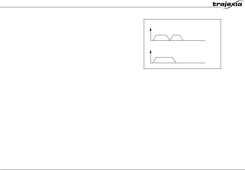
Merging moves
If the MERGE axis parameter is set to 1, a movement is always followed by a subsequent movement without stopping. The figures show the transitions of two moves with MERGE value 0 and value 1.
In the figure, A is the time axis and B is the speed axis.
Jogging
Jogging moves the axes at a constant speed forward or reverse by manual operation of the digital inputs. Different speeds are also selectable by input. Refer to the FWD_JOG, REV_JOG and FAST_JOG axis parameters.
fig. 14
B
MERGE=0
 A
A
B
MERGE=1
 A
A
2.3Servo system principles
The servo system used by and the internal operation of the TJ1-MC__ are briefly described in this section.
2.3.1Semi-closed loop system
The servo system of the TJ1-MC__ uses a semi-closed or inferred closed loop system. This system detects actual machine movements by the rotation of the motor in relation to a target value. It calculates the error between the target value and actual movement, and reduces the error through feedback.
0.5 Revision
HARDWARE REFERENCE MANUAL |
19 |
0.5 Revision
System philosophy
2.3.2Internal operation of the TJ1-MC__
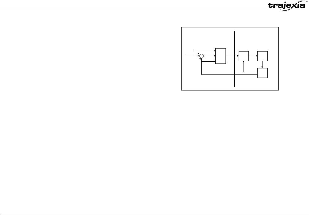
Inferred closed loop systems occupy the mainstream in modern servo systems applied to positioning devices for industrial applications. The figure shows the basic principle of the servo system as used in the TJ1-MC__.
1.The TJ1-MC__ performs actual position control. The main input of the controller is the Following Error, which is the calculated difference between the demand position and the actual measured position.
2.The Position Controller calculates the required speed reference output determined by the Following Error and possibly the demanded position and the measured position. The speed reference is provided to the Servo Driver.
3.The Servo Driver controls the rotational speed of the servo motor corresponding to the speed reference. The rotational speed is proportional to the speed reference.
4.The rotary encoder generates the feedback pulses for both the speed feedback within the Servo Driver speed loop and the position feedback within the TJ1-MC__ position loop.
fig. 15
|
|
A |
|
|
B |
|
|
2 |
|
3 |
|
C |
|
|
E |
|
|
1 |
D |
F |
G |
||
|
|
|
|||
|
|
|
|
|
4 |
|
|
|
|
|
I |
|
|
J |
|
|
H |
|
|
|
|
|
The labels in the figure are:
A.TJ1-MC__.
B.Servo system.
C.Demand position.
D.Position control.
E.Speed reference.
F.Speed control.
G.Motor.
H.Encoder.
I.Measured speed.
J.Measured position.
2.3.3Motion control algorithm
The servo system controls the motor by continuously adjusting the speed reference to the Servo Driver. The speed reference is calculated by the motion control algorithm of the TJ1-MC__, which is explained in this section.
HARDWARE REFERENCE MANUAL |
20 |
System philosophy
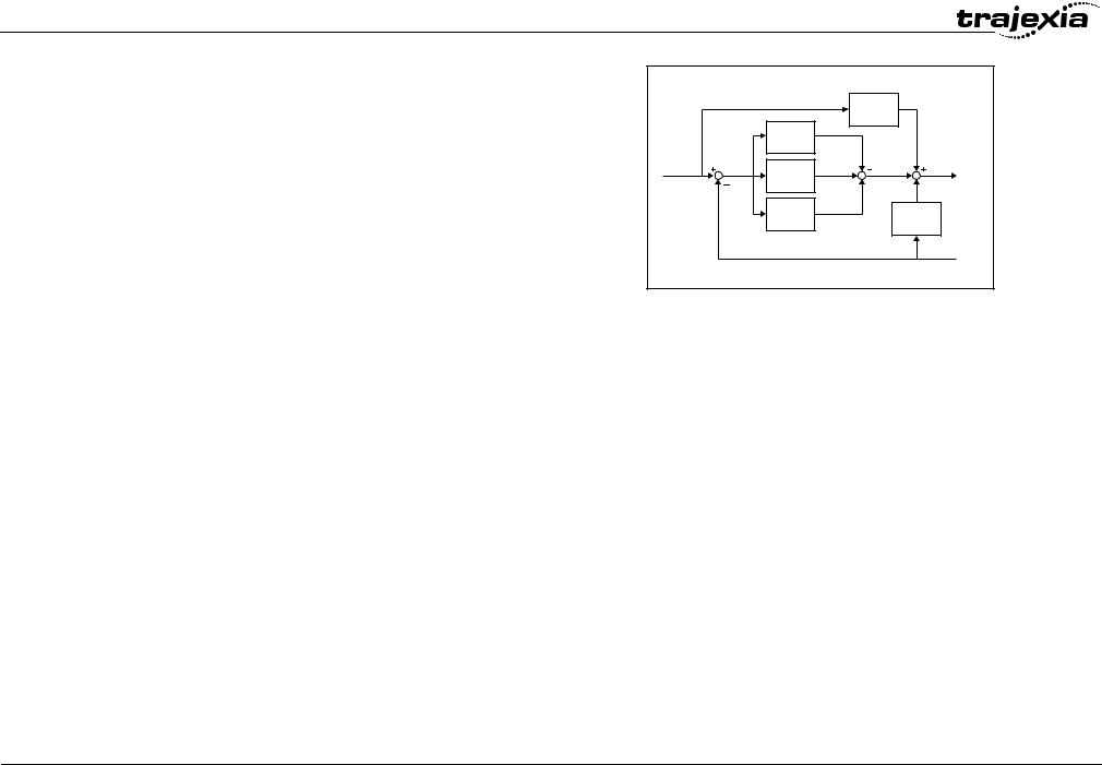
The motion control algorithm uses the demand position (A), the measured position (D) and the Following Error (B) to determine the speed reference. The Following Error is the difference between the demanded and measured position. The demand position, the measured position and the Following Error are represented by the axis parameters MPOS, DPOS and FE. Five gain values have been implemented for the user to be able to configure the correct control operation for each application.
C is the output signal.
•Proportional gain
The proportional gain Kp creates an output Op that is proportional to the Following Error E.
Op = Kp · E
All practical systems use proportional gain. For many just using this gain parameter alone is sufficient. The proportional gain axis parameter is called P_GAIN.
•Integral gain
The integral gain Ki creates an output Oi that is proportional to the sum of the Following Errors that have occurred during the system operation.
Oi = Ki · ΣE
Integral gain can cause overshoot and so is usually used only on systems working at constant speed or with slow accelerations. The integral gain axis parameter is called I_GAIN.
•Derivative gain
The derivative gain Kd produces an output Od that is proportional to the change in the Following Error E and speeds up the response to changes in error while maintaining the same relative stability.
Od = Kd · ∆E
Derivative gain may create a smoother response. High values may lead to oscillation. The derivative gain axis parameter is called D_GAIN.
•Output speed gain
The output speed gain Kov produces an output Oov that is proportional to the change in the measured position Pm and increases system damping.
Oov = Kov · ∆Pm
fig. 16
|
|
|
Kvff ∑ |
|
Kp |
|
|
A |
B |
∑ |
C |
|
Ki |
|
|
|
Kd ∆ |
Kov ∆ |
|
|
|
|
|
|
|
|
D |
0.5 Revision
HARDWARE REFERENCE MANUAL |
21 |

0.5 Revision
System philosophy
The output speed gain can be useful for smoothing motions but will generate high Following Errors. The output speed gain axis parameter is called OV_GAIN.
•Speed feed forward gain
The speed feedforward gain Kvff produces an output Ovff that is proportional to the change in demand position Pd and minimizes the Following Error at high speed.
Ovff = Kvff · ∆Pd
The parameter can be set to minimise the Following Error at a constant machine speed after other gains have been set. The speed feed forward gain axis parameter is called VFF_GAIN.
The default settings are given in the table along with the resulting profiles. Fractional values are allowed for gain settings.
Gain |
Default value |
|
|
Proportional gain |
0.1 |
|
|
Integral gain |
0.0 |
|
|
Derivative gain |
0.0 |
|
|
Output speed gain |
0.0 |
|
|
Speed feedforward gain |
0.0 |
|
|
2.4Trajexia system architecture
The system architecture of the Trajexia is dependant upon these concepts:
•Program control
•Motion Sequence
•Motion buffers
•Communication
•Peripherals
These concepts depend upon the value set in the SERVO_PERIOD parameter. The relationship between the value of SERVO_PERIOD and the different concepts of the system architecture are describes as follows.
2.4.1Program control
Programs make the system work in a defined way. The programs are written in a language similar to BASIC and control the application of the axes and modules. 14 Programs can be executed in parallel. The programs can be set to run at system power-up, started and stopped from other programs and executed from Trajexia Tools.
Programs execute commands to move the axes, control inputs and outputs and make communication via BASIC commands.
2.4.2Motion sequence
The motion sequence controls the position of all 16 axes with the actions as follows:
•Reading the Motion buffer
•Reading the current Measured Position (MPOS)
•Calculating the next Demanded Position (DPOS)
•Executing the Position loop
•Sending the Axis reference
•Error handling
2.4.3Motion buffers
Motion buffers are the link between the BASIC commands and the Axis control loop. When a BASIC motion command is executed, the command is stored in one of the buffers. During the next motion sequence, the profile generator executes the movement according to the information in the buffer. When the movement is finished, the motion command is removed from the buffer.
2.4.4Communication
All communication is carried out in the forth CPU task. A set of BASIC communication commands are used to configure the communications. When the Trajexia is a communication slave (as in the PROFIBUS communication) it is only necessary to configure the communication in an
HARDWARE REFERENCE MANUAL |
22 |
System philosophy
initial task. The values are exchanged from the configured global variables in a transparent way. When the Trajexia is a communications master, the BASIC communication commands are used to write and read.
2.4.5Peripherals
All inputs and outputs are used with the set of parameters (IN, OP, AIN, AOUT). The inputs and outputs are automatically detected and mapped in Trajexia. Inverters are considered a peripheral device and have a set of BASIC commands to control them. Various MECHATROLINK-II input and output modules can be connected to a TJ1-ML__ unit.
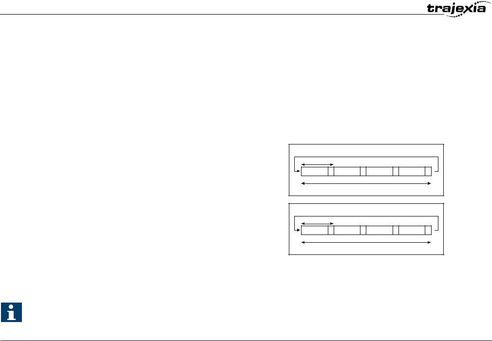
2.5Cycle time
All processes in the Trajexia system are based on the cycle time. The cycle time is divided into four CPU tasks:
•250 s time intervals for a SERVO_PERIOD of 0.5 and 1.0ms
•500 s time intervals for a SERVO_PERIOD of 2.0ms
The processes that can be carried out in each time interval depends on the
SERVO_PERIOD that is set.
The operations executed in each CPU task are:
CPU task |
Operation |
|
|
First CPU task |
Motion Sequence |
|
Low priority process |
|
|
Second CPU task |
High priority process |
|
|
Third CPU task |
1 Motion Sequence (only if SERVO_PERIOD=0.5ms) |
|
LED Update. |
|
High priority process |
|
|
Fourth CPU task |
External Communications |
|
|
fig. 17
250 s |
|
|
|
1 |
2 |
3 |
4 |
|
Cycle time = 1ms |
|
|
|
|
fig. 18 |
|
500 s |
|
|
|
1 |
2 |
3 |
4 |
|
Cycle time = 2 ms |
|
|
0.5 Revision
Note
The Motion sequence execution depends on setting of the
SERVO_PERIOD parameter.
HARDWARE REFERENCE MANUAL |
23 |

System philosophy
2.5.1Servo period
The SERVO_PERIOD can be set at 0.5, 1 or 2ms. The processes that take place within the cycle time depend on the setting of the SERVO_PERIOD parameter. The SERVO_PERIOD parameter is a Trajexia parameter that must be set according to the system configuration.
The factory setting is 1ms (SERVO_PERIOD=1000). A change is set only after a restart of the TJ1-MC__.
Note
Only the Sigma-III Servo Driver and the Sigma-V Servo Driver support the 0.5 ms transmission cycle.
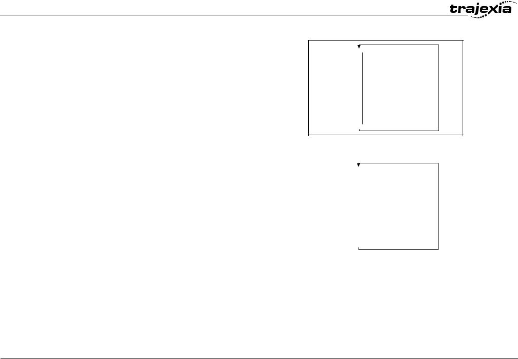
Example 1
The SERVO_PERIOD has a value of 0.5ms and the motion sequence is executed every 0.5ms.
fig. 19
|
|
|
|
|
CPU task 1 |
Motion sequence |
|
|
|
Low priority task (0,1,2,3...) |
|
|
|
|
|
|
CPU task 2 |
High priority task (13,14) |
|
|
CPU task 3 |
Motion sequence |
1ms |
|
|
LED refresh |
|
|
|
High priority task (13,14) |
|
|
CPU task 4 |
Communication |
|
|
|
|
|
|
|
|
|
0.5 Revision
HARDWARE REFERENCE MANUAL |
24 |
System philosophy
Example 2
The SERVO_PERIOD has a value of 1ms and the motion sequence is executed every 1ms. As the motion sequence is not executed during CPU task 3, there is more time for the program execution. High priority programs run faster.
fig. 20
CPU task 1 |
Motion sequence |
|
|
Low priority task (0,1,2,3...) |
|
|
|
|
CPU task 2 |
High priority task (13,14) |
|
CPU task 3 |
LED refresh |
1ms |
|
High priority task (13,14) |
|
CPU task 4 |
Communication |
0.5 Revision
Example 3
The SERVO_PERIOD has a value of 2ms and the motion sequence is executed every 2.0ms.
Servo period rules
The number of axes and MECHATROLINK-II devices in the Trajexia system determines the value of the SERVO_PERIOD system parameter.
There are 3 types of MECHATROLINK-II devices that are supported by the TJ1-MC__ units:
•Servo Drivers
The TJ1-MC__ considers Servo Drivers as axes.
•Inverters
The TJ1-MC__ does not consider Inverters as axes.
•I/O units and slice bus couplers
The TJ1-MC__ does not consider I/O units (analog and digital, counter and pulse) and slice bus couplers as axes.
You must obey the most restrictive rules when you set the SERVO_PERIOD parameter. An incorrect value of the SERVO_PERIOD parameter results in an incorrect detection of the MECHATROLINK-II devices.
The most restrictive rules are given in the tables below. For each unit the table lists the maximum number of devices the unit can control at the given
SERVO_PERIOD setting.
fig. 21
|
|
|
|
|
CPU task 1 |
Motion sequence |
|
|
|
Low priority task (0,1,2,3...) |
|
|
|
|
|
|
CPU task 2 |
High priority task (13,14) |
|
|
CPU task 3 |
LED refresh |
2ms |
|
|
High priority task (13,14) |
|
|
CPU task 4 |
Communication |
|
|
|
|
|
|
|
|
|
HARDWARE REFERENCE MANUAL |
25 |
Loading...