


NS10-TV
Table of contents
 Loading...
Omron NS10-TV, NS5-MQ, NS5-TQ, NS8-TV, NS12-TS SETUP MANUAL
...
Cat. No. V083-E1-17
NS-Series
NS15-TX_, NS12-TS_, NS10-TV_,
NS8-TV_,
NS5-SQ_, NS5-TQ_, NS5-MQ_
Programmable Terminals
SETUP MANUAL


Notice
OMRON products are manufactured for use according to proper procedures by a
qualified operator and only for the purposes described in this manual.
The following conventions are used to indicate and classify precautions in this manual.
Always heed the information provided with them. Failure to heed precautions can
result in injury to people or damage to property.
! DANGER Indicates an imminently hazardous situation which, if not avoided, will result in death or
serious injury. Additionally, there may be severe property damage.
! WARNING Indicates a potentially hazardous situation which, if not avoided, could result in death or
serious injury. Additionally, there may be severe property damage.
! Caution Indicates a potentially hazardous situation which, if not avoided, may result in minor or
moderate injury, or property damage.
OMRON Product References
All OMRON products are capitalized in this manual. The word "Unit" is also capitalized when
it refers to an OMRON product, regardless of whether or not it appears in the proper name of
the product.
The abbreviation "Ch," which appears in some displays and on some OMRON products,
often means "word" and is abbreviated "Wd" in documentation in this sense.
The abbreviation "PLC" means Programmable Controller.
The abbreviation "host" means a controller, such as an IBM PC/AT or compatible computer,
that controls a PT (Programmable Terminal).
Visual Aids
The following headings appear in the left column of the manual to help you locate different
types of information.
Precautions
for Safe Use
Precautions
for Correct Use
Note
Reference
1, 2, 3...
CS1G-CPU@@-V1
OMRON, 2003
All rights reserved. No part of this publication may be reproduced, stored in a retrieval system, or transmitted, in any form, or by
any means, mechanical, electronic, photocopying, recording, or otherwise, without the prior written permission of OMRON.
No patent liability is assumed with respect to the use of the information contained herein. Moreover, because OMRON is
constantly striving to improve its high-quality products, the information contained in this manual is subject to change without
notice. Every precaution has been taken in the preparation of this manual. Nevertheless, OMRON assumes no responsibility for
errors or omissions. Neither is any liability assumed for damages resulting from the use of the information contained in this
publication.
Indicates precautions on handling the product to ensure that the product is used
safely.
Indicates precautions to ensure that product functions and performances are
realized, to ensure that the reliability of the product is maintained, and to ensure
that the product is otherwise used correctly.
Indicates information of particular interest for efficient and convenient operation
of the product.
Indicates supplementary information on procedures, descriptions, and settings.
1. Indicates lists of one sort or another, such as procedures, checklists, etc.
Boxes in model numbers indicate variable characters. For example,
"CS1G-CPU@@-EV1" indicates the following models: CS1G-CPU42-EV1,
CS1G-CPU43-EV1, CS1G-CPU44-EV1, and CS1G-CPU45-EV1.
1

Contents
Notice .............................................................................................................................................1
About this Manual ...............................................................................................................................7
Related Manuals ..................................................................................................................................8
Terminology ........................................................................................................................................9
Introduction .......................................................................................................................................10
Section 1 Overview ................................................................................................. 1-1
1-1 NS-series PT Functions and Operation............................................................................................1-2
1-1-1 PT Functions for FA Manufacturing Sites........................................................................... 1-2
1-1-2 NS-series PT Operating System........................................................................................... 1-3
1-2 Communications with the Host ....................................................................................................... 1-5
1-2-1 What is an NT Link?............................................................................................................ 1-6
1-2-2 Ethernet................................................................................................................................ 1-6
1-2-3 Controller Link..................................................................................................................... 1-6
1-2-4 Host Link ............................................................................................................................. 1-6
1-2-5 Connecting to a Temperature Controller.............................................................................. 1-6
1-2-6 Memory Link Connections .................................................................................................. 1-7
1-2-7 Communicating with Other Devices.................................................................................... 1-7
1-2-8 EtherNet/IP .......................................................................................................................... 1-7
1-3 System Configuration ...................................................................................................................... 1-8
1-3-1 Supported Peripheral Devices.............................................................................................. 1-8
1-4 Procedure for Running NS-series PTs ........................................................................................... 1-10
Section 2 Before Connecting ................................................................................... 2-1
2-1 Connecting the Host ........................................................................................................................ 2-2
2-1-1 Communications Types and Connection Methods............................................................... 2-2
2-2 Part Names and Functions ............................................................................................................... 2-8
Section 3 Installing the PT and Connecting Peripheral Devices......................... 3-1
3-1 Installing the PT .............................................................................................................................. 3-3
3-1-1 Installation Environment...................................................................................................... 3-3
3-1-2 Installing RS-232C/RS-422A Converters ............................................................................ 3-4
3-1-3 Mounting the PT to the Control Panel ................................................................................. 3-4
3-1-4 Connecting the Power Supply.............................................................................................. 3-7
3-1-5 Wiring the Ground Wire ...................................................................................................... 3-8
3-1-6 Peripheral Device Connection Limitations .......................................................................... 3-8
3-2 Starting the PT ............................................................................................................................... 3-10
3-2-1 Operation at Startup ........................................................................................................... 3-10
3-2-2 Starting the PT for the First Time ...................................................................................... 3-12
3-3 Connecting the CX-Designer......................................................................................................... 3-14
3-3-1 Connecting via RS-232C or Ethernet................................................................................. 3-14
3-3-2 Connecting via USB........................................................................................................... 3-14
3-3-3 Connecting via a Modem ................................................................................................... 3-16
3-4 Connecting to Bar Code Readers................................................................................................... 3-17
3-4-1 Connection Methods .......................................................................................................... 3-17
3-4-2 Setting Bar Code Readers .................................................................................................. 3-18
2

3-4-3
Data Format ....................................................................................................................... 3-19
3-4-4 Bar Code Input................................................................................................................... 3-19
3-5 Connecting to Printers ................................................................................................................... 3-20
3-5-1 Connecting to a Printer Compatible with ESC/P Raster and BJ Raster............................. 3-20
3-5-2 Connecting a PictBridge-compatible Printer...................................................................... 3-21
3-6 Using Memory Cards..................................................................................................................... 3-23
3-6-1 Installation.......................................................................................................................... 3-24
3-6-2 Replacing the System Program.......................................................................................... 3-25
3-6-3 Transferring Data with Memory Cards .............................................................................. 3-26
3-7 Installing the Video Input Unit ...................................................................................................... 3-32
3-7-1 Video Input Unit Components........................................................................................... 3-32
3-7-2 Nomenclature and Functions.............................................................................................. 3-33
3-7-3 Installation Method for Video Input Unit .......................................................................... 3-34
3-7-4 Connecting to Video Input Connectors.............................................................................. 3-39
3-8 Installing the Controller Link Interface Unit ................................................................................. 3-44
3-8-1 Controller Link Interface Unit Components ...................................................................... 3-44
3-8-2 Nomenclature and Functions.............................................................................................. 3-45
3-8-3 Installation Method for Controller Link Interface Unit...................................................... 3-48
3-8-4 Wiring ................................................................................................................................ 3-55
3-9 Connecting a Monitor .................................................................................................................... 3-61
3-10 External Brightness Adjustment .................................................................................................... 3-62
3-11 RS-232C/RS-422A Selector DIP Switch....................................................................................... 3-63
Section 4 Connecting the Host to Serial Port........................................................ 4-1
4-1 1:1 Host Connection ........................................................................................................................ 4-2
4-1-1 Connection Methods ............................................................................................................ 4-2
4-1-2 Unit Setting Methods ........................................................................................................... 4-4
4-2 1:N Host Connection ....................................................................................................................... 4-7
4-2-1 Connection Methods ............................................................................................................ 4-7
4-2-2 Unit Setting Methods ........................................................................................................... 4-7
4-3 High-speed 1:N NT Link............................................................................................................... 4-18
4-3-1 Unit Setting Methods ......................................................................................................... 4-19
4-4 Recommended Connector Cables.................................................................................................. 4-27
Section 5 Connecting to Host via Ethernet or Controller Link............................... 5-1
5-1 Connecting to Host Via Ethernet..................................................................................................... 5-2
5-1-1 Host Types and Settings....................................................................................................... 5-3
5-2 Connecting to the Host Using Controller Link .............................................................................. 5-18
5-2-1 What Is a Controller Link Network?.................................................................................. 5-18
5-2-2 Data Links.......................................................................................................................... 5-19
5-2-3 Troubleshooting Using Indicators...................................................................................... 5-24
5-3 Connecting to Host via EtherNet/IP ..............................................................................................5-27
5-3-1 What is EtherNet/IP? ......................................................................................................... 5-27
5-3-2 Setting Individual Units ..................................................................................................... 5-28
Section 6 System Menu Operations ....................................................................... 6-1
6-1 Operating Modes and System Menu................................................................................................ 6-3
6-1-1 Mode Configuration............................................................................................................. 6-3
3

6-1-2
System Menu Configuration ................................................................................................ 6-3
6-1-3 Overview of Menu Items ..................................................................................................... 6-4
6-1-4 Using the System Menu ....................................................................................................... 6-7
6-2 Initializing and Saving Data and Removing the Memory Card..................................................... 6-10
6-2-1 Screen Data Area Format................................................................................................... 6-11
6-2-2 Initializing or Saving the Alarm/Event History ................................................................. 6-12
6-2-3 Initializing and Saving Data Log ....................................................................................... 6-14
6-2-4 Initializing and Saving the Operation Log ......................................................................... 6-15
6-2-5 Initializing and Saving the Error Log................................................................................. 6-17
6-2-6 Language Selection............................................................................................................ 6-18
6-2-7 Removing the Memory Card.............................................................................................. 6-19
6-2-8 Initializing Internal Holding Memories ($HB/$HW)......................................................... 6-20
6-3 PT Settings .................................................................................................................................... 6-21
6-3-1 Start-up Wait Time............................................................................................................. 6-23
6-3-2 Screen Saver....................................................................................................................... 6-24
6-3-3 Key Press Sound ................................................................................................................ 6-25
6-3-4 Buzzer Sound ..................................................................................................................... 6-25
6-3-5 Backlight Brightness.......................................................................................................... 6-26
6-3-6 Calendar Check..................................................................................................................6-27
6-3-7 Printer Type ....................................................................................................................... 6-28
6-3-8 Printing Mode .................................................................................................................... 6-28
6-3-9 Orientation ......................................................................................................................... 6-29
6-3-10 Changing Values in Device Monitor Setting ..................................................................... 6-29
6-3-11 Contrast (NS5-SQ@@/NS5-MQ@@ Only) ..................................................................... 6-29
6-3-12 CJK Han Unification Priority............................................................................................. 6-30
6-3-13 Alarm Monitor Registration Procedure.............................................................................. 6-30
6-3-14 Starting the Ladder Monitor from Alarm/Event Summary and History
(NS15/12/10/8 Only).......................................................................................................... 6-31
6-3-15 Setting the Tag Update Notification Message.................................................................... 6-31
6-3-16 Time to Switch to System Menu (NS12, NS10, NS8, or NS5).......................................... 6-31
6-3-17 Double-touch Interval (NS15 Only)................................................................................... 6-32
6-3-18 Analog RGB Output (NS15 only)...................................................................................... 6-32
6-4 Project Settings .............................................................................................................................. 6-33
6-4-1 Project Title........................................................................................................................ 6-33
6-4-2 Number of Labels............................................................................................................... 6-34
6-4-3 Initial Screen ...................................................................................................................... 6-34
6-4-4 Initial Label........................................................................................................................ 6-34
6-4-5 Alarm/Event History Recording Method ........................................................................... 6-34
6-4-6 Data Log Recording Method.............................................................................................. 6-34
6-4-7 Operation Log Recording Method ..................................................................................... 6-35
6-4-8 Error Log Recording Method............................................................................................. 6-35
6-4-9 System Memory................................................................................................................. 6-35
6-5 Setting Passwords .......................................................................................................................... 6-36
6-5-1 Changing the Password...................................................................................................... 6-36
6-5-2 Setting the Password Function........................................................................................... 6-37
4

6-6
Communications Settings .............................................................................................................. 6-39
6-6-1 Communications Conditions.............................................................................................. 6-39
6-6-2 Setting 1:1 NT Link ........................................................................................................... 6-41
6-6-3 Setting High-speed 1:N NT Links (Standard, High-speed)................................................ 6-42
6-6-4 Setting Ethernet.................................................................................................................. 6-42
6-6-5 Setting the Controller Link Network.................................................................................. 6-45
6-6-6 Setting Bar Code Readers .................................................................................................. 6-46
6-6-7 Modem Settings ................................................................................................................. 6-47
6-7 Screen Data Check ........................................................................................................................ 6-48
6-8 Special Screens .............................................................................................................................. 6-49
6-8-1 Alarm History .................................................................................................................... 6-50
6-8-2 Operation Log .................................................................................................................... 6-51
6-8-3 Error Log............................................................................................................................ 6-52
6-8-4 Device Monitor ..................................................................................................................6-53
6-8-5 Communication Test.......................................................................................................... 6-55
6-8-6 Video Configuration .......................................................................................................... 6-57
6-8-7 USB Device List ................................................................................................................ 6-59
6-8-8 Display Capture Data......................................................................................................... 6-60
6-8-9 Memory Card Transfers..................................................................................................... 6-61
6-8-10 External Application Startup.............................................................................................. 6-63
6-8-11 Version Display .................................................................................................................6-64
6-8-12 PLC Data Trace (NS15, NS12, NS10, and NS8 Only) ...................................................... 6-64
6-9 Hardware Check ............................................................................................................................ 6-66
6-9-1 LCD Check ........................................................................................................................ 6-66
6-9-2 Touch Switch Check .......................................................................................................... 6-67
6-9-3 Touch Panel Calibration (NS15 Only)............................................................................... 6-67
6-10 Starting Operations ........................................................................................................................ 6-68
6-11 Verifying Tags............................................................................................................................... 6-70
Section 7 Maintenance and Troubleshooting........................................................ 7-1
7-1 Maintenance .................................................................................................................................... 7-2
7-1-1 Replacing the Battery...........................................................................................................7-2
7-2 Inspection and Cleaning .................................................................................................................. 7-4
7-3 Troubleshooting and Maintenance .................................................................................................. 7-6
7-4 Requesting a Replacement PT ....................................................................................................... 7-14
Appendices .................................................................................................................. A-1
Appendix 1 Specifications...................................................................................................................... A-3
A-1-1 General Specifications ........................................................................................................ A-3
A-1-2 Characteristics..................................................................................................................... A-5
A-1-3 Communications Specifications.......................................................................................... A-8
Appendix 2 Dimensions ....................................................................................................................... A-12
Appendix 3 Using NS-AL002 Converters............................................................................................ A-21
A-3-1 Dimensions ....................................................................................................................... A-21
A-3-2 Mounting and Removing .................................................................................................. A-22
A-3-3 Specifications.................................................................................................................... A-22
A-3-4 DIP Switch Settings .......................................................................................................... A-23
5

A-3-5
Pin Arrangement ............................................................................................................... A-24
A-3-6 Handling the Shield on RS-422A/485 Cables................................................................... A-25
A-3-7 Connection Example......................................................................................................... A-28
Appendix 4 Using NT-AL001 Converters............................................................................................ A-29
A-4-1 Dimensions ....................................................................................................................... A-29
A-4-2 Methods for Mounting and Removal ................................................................................ A-29
A-4-3 Specifications.................................................................................................................... A-31
A-4-4 DIP Switch Settings .......................................................................................................... A-32
A-4-5 Pin Arrangement ............................................................................................................... A-33
A-4-6 Block Diagram .................................................................................................................. A-34
Appendix 5 Preparing Connecting Cables............................................................................................ A-35
A-5-1 Cable Preparation.............................................................................................................. A-35
A-5-2 Soldering........................................................................................................................... A-36
A-5-3 Hood Assembly................................................................................................................. A-36
A-5-4 Preparing Connecting Cables for Host Connection .......................................................... A-37
Appendix 6 Preparing Cables for Computer Connection ..................................................................... A-41
A-6-1 Connecting Cable Assembly............................................................................................. A-41
Appendix 7 Preparing Connecting Cables for Bar Code Readers ........................................................ A-43
Appendix 8 Standard Models ............................................................................................................... A-44
Appendix 9 List of Optional Products .................................................................................................. A-60
A-9-1 Anti-reflection Sheets: NS15-KBA04, NS12-KBA04, NS7-KBA04, NT30-KBA04 ...... A-60
A-9-2 Protective Covers: NS15-KBA05N, NS12-KBA05(N), NS7-KBA05(N),
NT31C-KBA05(N) ........................................................................................................... A-61
A-9-3 NT30-KBA01 Chemical-resistant Cover.......................................................................... A-62
A-9-4 Replacement Battery: CJ1W-BAT01................................................................................ A-62
A-9-5 Recommended Memory Cards.......................................................................................... A-63
A-9-6 NS-CLK21 Controller Link Interface Unit ....................................................................... A-63
A-9-7 NS-CA001/CA002 Video Input Unit................................................................................ A-63
A-9-8 Attachments: NS12-ATT01(B)/NS12-ATT02/NS8-ATT01/ NS8-ATT02 ...................... A-63
A-9-9 NS-USBEXT-1M USB Relay Cable................................................................................. A-64
Appendix 10 System Memory List ..................................................................................................... A-65
Appendix 11 Differences between "-V1"/"-V2" Models and Other Models ...................................... A-68
Appendix 12 NS5 System Menu......................................................................................................... A-70
6

About this Manual
Section 1 Overview
This section provides an overview of the NS-series PTs, including functions, features, connection types, and
communications methods.
Section 2 Before Connecting
This section provides information on methods for connecting NS-series PTs that must be understood before connecting
the host and peripheral devices.
Section 3 Installing the PT and Connecting Peripheral Devices
This section describes the methods used to install the PT and connect peripheral devices.
Section 4 Connecting Host to Serial Port
This section describes the methods for connecting the host to the serial port of the PT.
Section 5 Connecting to Host via Ethernet or Controller Link
This section describes the methods for connecting the PT to the host using the PT’s Ethernet interface and the Controller
Link Interface Unit.
Section 6 System Menu Operations
This section describes the methods for operating the System Menu. It also provides details on functions that are useful
for NS-series PT applications and for system maintenance.
Section 7 Maintenance and Troubleshooting
This section describes the maintenance and inspection methods for preventing errors occurring, and troubleshooting
measures when errors occur in the PT.
Appendices
Describe hardware specifications and methods for preparing connections cables, and provide lists of standard products.
WARNING
Failure to read and understand the information provided in this manual may result in
personal injury or death, damage to the product, or product failure. Please read each
section in its entirety and be sure you understand the information provided in the section
and related sections before attempting any of the procedures or operations given.
7

Related Manuals
The following manuals are used for NS-series PTs. (The boxes at the end of the catalog
numbers indicate the revision code.)
manual
This
NS Series -V1/-V2 Setup Manual ...............................................V083-E1-@
Provides information on NS Series V1 and V2 PTs (i.e., NS15-V2, NS12-V@, NS10-V@,
NS8-V@, and NS5-V@).
Describes how to connect the PT to the host and peripheral devices, methods to setup
communications and operation, and procedures for maintenance.
Refer to the NS Series Programming Manual (V073-E1-@) for information on PT
functions and specific operating procedures.
NS Series Setup Manual.............................................................V072-E1-@
Provides information on NS Series PTs prior to V1 (i.e., NS12, NS10, and NS7).
Describes how to connect the PT to the host and peripheral devices, methods to setup
communications and operation, and procedures for maintenance.
Refer to the NS Series Programming Manual (V073-E1-@) for information on PT
functions and specific operating procedures.
NS Series Programming Manual ................................................V073-E1-@
Describes the screen configurations, object functions, and host communications for the
PT.
CX-Designer User’s Manual .......................................................V099-E1-@
The screens displayed on the PT can be created in the CX-Designer and transferred
between the CX-Designer and PT. This manual describes the installation and features
of the CX-Designer. For details on CX-Designer operations, refer to the CX-Designer’s
Online Help.
8

Terminology
PT In this manual, indicates an NS-series Programmable Terminal.
NS Series
PLC Indicates a Programmable Controller in the OMRON SYSMAC CS/CJ, C, or
CS/CJ Series Indicates Programmable Controllers in the OMRON SYSMAC CS/CJ Series of
C Series Indicates products in the OMRON SYSMAC C Series of Programmable Controllers:
CVM1/CV Series Indicates products in the OMRON SYSMAC CVM1/ CV Series of Programmable
Serial Communications Unit Indicates a Serial Communications Unit for an OMRON CS/CJ-series PLC.
Serial Communications Board Indicates a Serial Communications Board for an OMRON CS-series or CQM1H
Communications Board Indicates a Communications Board for an OMRON C200HX/HG/HE(-Z) PLC.
CPU Unit Indicates a CPU Unit in the OMRON SYSMAC CS/CJ, C, or CVM1/CV Series of
CX-Designer
The following terminology is used in this manual.
Indicates products in the OMRON NS@@ Series of Programmable Terminals.
CVM1/CV Series of Programmable Controllers.
Programmable Controllers: CS1G, CS1H, CS1G-H, CS1H-H, CJ1G, CJ1G-H,
CJ1H-H, CJ1M, CP1H, CP1L, CJ2H, CJ2M.
In this manual, “CJ1H-H” indicates the CJ1H-CPU@@H-R and CJ1H-CPU@@H
CPU Units. “CJ1H-H-R” is used to indicate only the CJ1H-CPU @@H-R CPU Units.
The “CP Series” is used to indicate only the CP1H and CP1L.
C200HS, C200HX(-Z), C200HG(-Z), C200HE(-Z), CQM1, CQM1H, CPM1A,
CPM2A, CPM2C.
Controllers: CV500, CV1000, CV2000, CVM1
PLC.
Programmable Controllers.
Indicates the OMRON CX-Designer (NS-CXDC1-V@).
Host Indicates the PLC, IBM PC/AT or compatible computer, or personal computer
functioning as the control device and interfaced with the NS-series PT.
Programming Manual
Indicates the NS Series Programming Manual (V073-E1-@).
9

Introduction
• Intended Audience
This manual is intended for the following personnel, who must also have knowledge of
electrical systems (an electrical engineer or the equivalent).
• Personnel in charge of introducing FA systems into production facilities.
• Personnel in charge of designing FA systems.
• Personnel in charge of installing and connecting FA systems.
• Personnel in charge of managing FA systems and facilities.
• General Precautions
• The user must operate the product according to the performance specifications
described in the operation manuals.
• Do not use the PT touch switch input functions for applications where danger to human
life or serious property damage is possible, or for emergency switch applications.
• Before using the product under conditions which are not described in the manual or
applying the product to nuclear control systems, railroad systems, aviation systems,
vehicles, combustion systems, medical equipment, amusement machines, safety
equipment, and other systems, machines and equipment that may have a serious
influence on lives and property if used improperly, consult your OMRON representative.
• Make sure that the ratings and performance characteristics of the product are sufficient
for the systems, machines, and equipment, and be sure to provide the systems,
machines, and equipment with double safety mechanisms.
• This manual provides information for connecting and setting up an NS-series PT. Be
sure to read this manual before attempting to use the PT and keep this manual close at
hand for reference during installation and operation.
10
Safety Precautions
Notation Used for Safety Information
The following notation is used in this manual to provide precautions required to ensure safe
usage of the product.
The safety precautions that are provided are extremely important to safety.
Always read and heed the information provided in all safety precautions.
The following notation is used.
! WARNING
Symbols
Prohibition
Indicates a general prohibition
Indicates a potentially hazardous situation which, if not avoided,
will result in minor or moderate injury, or may result in serious
injury or death. Additionally there may be significant property
damage.
Caution
Indicates general cautionary, warning, or danger
level information
Always ensure that the personnel in charge confirm
that installation, inspection, and maintenance were
properly performed for the PT. “Personnel in charge”
refers to individuals qualified and responsible for
ensuring safety during machine design, installation,
operation, maintenance, and disposal.
Ensure that installation and post-installation checks are
performed by personnel in charge who possess a
thorough understanding of the machinery to be
installed.
Do not use the input functions of the PT, such as the
function switches or switches on the touch panel, in
applications that involve human life, in applications that
may result in serious injury, or for emergency stop
switches.
Do not attempt to disassemble, repair, or modify the PT.
Doing so may impair the safety functions.
Do not attempt to take the Unit apart and do not touch
any internal parts while the power is being supplied.
Doing either of these may result in electrical shock.
The NS15-TX01@-V2 uses an analog touch panel.
Never press more than two points on the panel at a
time. Otherwise, it may activate a switch somewhere
between the two points.
11

Precautions for Safe Use
1. When unpacking the Units, check carefully for any external scratches or other damage.
Also, shake the Units gently and check for any abnormal sound.
2. The PT must be installed in a control panel.
3. The mounting panel must be between 1.6 and 4.8 mm thick. Tighten the Mounting
Brackets evenly to a torque of between 0.5 and 0.6 N⋅m to maintain water and dust
resistance. Make sure the panel is not dirty or warped and that it is strong enough to hold
the Units.
4. Do not let metal particles enter the Units when preparing the panel.
5. Do not connect an AC power supply to the DC power input terminals.
6. Use a DC power supply with minimal voltage fluctuation that provides a stable output even
if the power supply input is interrupted for 10 ms. The DC power supply must also have
reinforced or double insulation.
Rated power supply voltage: 24 VDC (Allowable range: 20.4 to 27.6 VDC)
Capacity: NS15: 45 W min.
NS12, NS10, or NS8: 25 W min.
NS5: 15 W min.
7. Do not perform a dielectric voltage test.
8. Use a twisted-pair cable with a cross-sectional area of at least 2 mm
power terminals and always use M3.5 crimp terminals. Tighten the terminal screws to a
torque of 0.8 N⋅m. Make sure the screws are properly tightened.
9. Ground the Unit correctly to prevent operational errors caused by noise.
10. Do not touch the surface of the circuit board or the components mounted on it with your
bare hands. Discharge any static electricity from your body before handling the board.
11. Confirm that the current capacity of the connected device is 250 mA or less before using
the 5-V power supply from pin 6 of the RS-232C connector. The 5-V output from the PT is
250 mA max. at 5 V ±5%.
12. Turn OFF the power supply before connecting or disconnecting cables.
13. Always tighten the connector screws after connecting communications cables.
14. The maximum tensile load for cables is 30 N. Do not apply loads greater than this.
15. Confirm the safety of the system before turning ON or OFF the power supply or before
pressing the reset button.
16. The whole system may stop depending on how the power supply is turned ON or OFF.
Turn ON or OFF the power supply according to the specified procedure.
17. After changing the settings of the DIP switch, always turn the power supply OFF and ON
or reset the PT.
18. Do not perform the following operations while the Memory Card is being accessed:
• Turning OFF the power supply to the PT
• Pressing the PT’s reset switch
• Removing the Memory Card
19. To ensure system safety, incorporate a program that periodically calls PT operation bits
from the host side to check that the PT is properly operating.
20. Start actual system application only after sufficiently checking screen data, macros, and
the operation of the program in the host.
21. Do not press a touch switch with a force greater than 30 N.
22. Do not operate a touch switch using a screwdriver or other tool.
23. Confirm the safety of the system before pressing a touch switch.
24. Do not press touch switches consecutively without pausing in between. If touch switches
are pressed consecutively at high speed, the PT may not be able to detect the inputs.
Confirm that the PT has detected the input of a touch switch before pressing any other
touch switch.
25. Do not accidentally press touch switches when the backlight is not lit or when the display
does not appear. Confirm the safety of the system before pressing touch switches.
2
to connect to the
12

26. To ensure safety when using numeral input functions, set the upper and lower limits for the
input value.
27. Before initializing screen data, confirm that existing data is backed up at the CX-Designer.
28. When changing the password with the system menu, do not reset or turn OFF the power
supply until writing is finished.
29. When using the device monitor, confirm the safety of the system before performing the
following operations.
• Changing monitor data
• Changing operation modes
• Forced setting or resetting
• Changing present values or set values
30. Dispose of any battery that has been dropped on the floor or otherwise subjected to
excessive shock.
31. Do not connect an USB connector to any device that is not applicable.
32. Before connecting an USB connector to a device, make sure that the device is free of
damage.
33. Commercially available USB hubs and the recommended USB hub do not necessarily
have the same general specifications as the PT, and may not function properly if used in
environments subject to static electricity or other forms of noise. When using a USB hub,
take sufficient measures to prevent static electricity and other forms of noise, or do not
install the PT in an environment subject to such noise.
34. Do not perform the following operations while downloading or uploading screen data or
system program. Doing so may corrupt the screen data or system program.
• Turning OFF the power supply to the PT
• Pressing the PT’s reset switch
35. When mounting the Battery, be sure to use the correct Battery and mount it correctly.
36. Do not disassemble or short-circuit the battery.
37. Dispose of the Units and batteries according to local ordinances as they apply.
38. Never use volatile solvents, such as benzene or thinners, or chemical dusters to clean the
PT.
39. The backlight in the NS-series PT contains mercury. Do not dispose of the PT together
with waste to be processed at disposal plants. Dispose of the PT according to all local
laws, regulations, and ordinances.
40. The backlight in the PT cannot be replaced by the user. Contact your OMRON
representative for backlight replacement.
41. Periodically check the installation conditions in applications where the PT is subject to
contact with oil or water.
The NS15-TX01@-V2 uses an analog touch panel. Deterioration over time can cause the
42.
touch points to move. If the touch points move too far, calibrate the touch panel.
43. Never connect more than two crimp terminals to one terminal.
44. Water and oil resistance will be lost if the front sheet is torn or is peeling off. Do not use
the PT if the front sheet is torn or is peeling off.
45. The Rubber Packing will deteriorate, shrink, expand, or harden depending on the
operating environment. Inspect and replace the Rubber Packing periodically.
13

Precautions for Correct Use
1. Do not install the Unit in the following places:
• Locations subject to severe changes in temperature.
• Locations subject to direct sunlight
• Locations subject to temperatures or humidity outside the range specified in the
specifications
• Locations subject to condensation as the result of high humidity
• Locations subject to corrosive or flammable gases
• Locations subject to shock or vibration
• Outdoor locations directly subject to wind or rain
• Locations subject to strong ultraviolet light
• Locations subject to excessive dust
• Locations subject to direct sunlight
2. Take appropriate and sufficient countermeasures when installing systems in the following
locations:
• Locations subject to static electricity or other forms of noise
• Locations subject to strong electromagnetic fields
• Locations close to power supplies
• Locations subject to possible exposure to radioactivity
14

Conformance to EC Directives
This product is EMC compliant.
• Concepts
OMRON products are electronic devices that are incorporated in machines and manufacturing
installations. OMRON PTs conform to the related EMC Directives (see note) so that the
devices and machines into which they are built can more easily conform to EMC directives.
However, customers may use a wide variety of equipment and manufacturing installations.
Therefore the customer must check whether the Directives are satisfied for the actual system.
EMC-related performance will vary depending on the configuration, wiring, and other
conditions of the equipment or control panel in which the PT is installed. The customer must,
therefore, perform final checks to confirm that the overall machine or device conforms to EMC
standards.
Note: Applicable EMC (Electromagnetic Compatibility) standards are as follows:
EMS (Electromagnetic Susceptibility): EN 61131-2
EMI (Electromagnetic Interference): EN 61131-2
(EN 61131-2 radiated emission: 10-m regulations)
• Conformance to EC Directives
NS-series PTs conform to EC Directives. To ensure that the machine or device in which the
NS-series PT is used complies with EC Directives, the PT must be installed as follows:
• The NS-series PT must be installed in a control panel.
• You must use reinforced insulation or double insulation for the DC power supply and the
DC power supply must have minimal voltage fluctuations and provide a stable output
even if the power supply input is interrupted for 10 ms.
• NS-series PTs complying with EC Directives also conform to the Common Emission
Standard (EN 61131-2). Radiated emission characteristics (10-m regulations) may vary
depending on the configuration of the control panel used, other devices connected to
the control panel, wiring, and other conditions. You must therefore confirm that the
overall machine or equipment complies with EC Directives.
• This is a class A product. It may cause radio interference in residential areas, in which
case the user may be required to take adequate measures to reduce interference.
15

Conformance to Shipbuilding Standards
This product complies with shipping standards. Application conditions are set for compliance
for individual shipping standards, and it may not be possible to use the product in some
installation locations. Contact an OMRON sales representative before using the product.
• International Shipping Standards
Shipping Standards of Various Countries
Abbreviation Country Name
NK Japanese Nippon Kaiji Kyokai
LR Great Britain Lloyd’s Register of Shipping
DNV Norway Det Norske Veritas
RINA Italy Registro Italiano Navale
BV France Bureau Veritas
GL Germany Germanischer Lloyd
ABS USA American Bureau of Shipping
KR South Korea Korean Register of Shipping
CR Taiwan China Corporation Register of Shipping
• Certification Status for NS-series Programmable Terminals
The following table shows the compliance status with shipping standards for NS-series
Programmable Terminals as of April 2009.
Abbreviation NS5 NS8 NS10 NS12 NS15
NK
LR
DNV
RINA
BV
GL (See note.)
ABS
KR
CR
Yes Yes Ye s Ye s Ye s
Yes Yes Yes Yes Yes
Yes Yes Yes Yes No
No No No No No
Yes Yes Yes Yes No
Conditional Conditional Conditional Conditional No
Yes Yes Yes Yes No
Yes Yes Yes Yes No
No No No No No
Note: GL certification has been received only for the NS**-V1.
• Certification Zones for Shipping Standards
2. Bridge
Air conditioning
No air conditioning
3. Deck
Devices on deck or bridge
16
Devices not on deck or bridge
Sea
1. Boiler room
Air conditioning
No air
conditioning
4. Engine room
5. Depends on ship type
Emergency power supply devices on
bulk carrier ships carrying liquefied gas
or hazardous chemicals

1. Zones with and without air conditioning not on the bridge or deck (e.g., boiler room)
2. Zones with and without air conditioning on the bridge (e.g., helm room)
3. Deck zone
4. Engine room zone (devices mounted on machinery that has strict vibration conditions,
such as diesel engines or air compressors)
5. Depends on the ship type. Emergency power supply devices on bulk carrier ships
carrying liquefied gas or hazardous chemicals.
• Certification Zones for Shipping Standards
1. Not on deck or bridge 2. Bridge Standard
No air
conditioning
NK No Yes No Yes No No No
LR No Yes No Yes No No No
DNV No Yes No No No No No
RINA No No No No No No No
BV No Yes No No No No No
GL No Yes No No No No No
ABS No Yes No No No No No
KR No Yes No No No No No
CR No No No No No No No
Air
conditioning
No air
conditioning
Air
conditioning
3.
Deck
4.
Engine
(e.g.)
5. Ship type
(e.g., bulk ship
with liquefied
gas)
• Precautions for Compliance with Shipping Standards
1. Always install the NS-series PT in a control panel.
2. Install the NS-series PT in a control panel that has air conditioning.
3. Cover the entire surface of the NS-series PT with electromagnetic shielding material and
ground the control panel or operation panel with copper tape or other conductive tape.
4. Completely shield the gap at openings in the control panel or operation panel with a
gasket.
5. Completely shield the gap between the NS-series PT and the panel cutout with copper
tape or other conductive tape before securing the NS-series PT with the mounting
bracket.
6. Connect a noise filter to the power supply line connected between the 24-VDC and
0-VDC terminals.
Electromagnetic Shielding
Manufacturer Seiwa Electric Mfg. Co. Ltd.
Model E09F-100, E09R13502P
Note: The transmission rate of the liquid crystal display will decrease by approximately
50% when the electromagnetic shielding is mounted.
Noise Filter
Manufacturer Cosel Co. Ltd.
Model TAH-06-683
17

Read and Understand this Manual
Please read and understand this manual before using the product. Please consult your OMRON
representative if you have any questions or comments.
Warranty and Limitations of Liability
WARRANTY
OMRON's exclusive warranty is that the products are free from defects in materials and workmanship for a
period of one year (or other period if specified) from date of sale by OMRON.
OMRON MAKES NO WARRANTY OR REPRESENTATION, EXPRESS OR IMPLIED, REGARDING
NON-INFRINGEMENT, MERCHANTABILITY, OR FITNESS FOR PARTICULAR PURPOSE OF THE
PRODUCTS. ANY BUYER OR USER ACKNOWLEDGES THAT THE BUYER OR USER ALONE HAS
DETERMINED THAT THE PRODUCTS WILL SUITABLY MEET THE REQUIREMENTS OF THEIR
INTENDED USE. OMRON DISCLAIMS ALL OTHER WARRANTIES, EXPRESS OR IMPLIED.
LIMITATIONS OF LIABILITY
OMRON SHALL NOT BE RESPONSIBLE FOR SPECIAL, INDIRECT, OR CONSEQUENTIAL DAMAGES,
LOSS OF PROFITS OR COMMERCIAL LOSS IN ANY WAY CONNECTED WITH THE PRODUCTS,
WHETHER SUCH CLAIM IS BASED ON CONTRACT, WARRANTY, NEGLIGENCE, OR STRICT
LIABILITY.
In no event shall the responsibility of OMRON for any act exceed the individual price of the product on
which liability is asserted.
IN NO EVENT SHALL OMRON BE RESPONSIBLE FOR WARRANTY, REPAIR, OR OTHER CLAIMS
REGARDING THE PRODUCTS UNLESS OMRON'S ANALYSIS CONFIRMS THAT THE PRODUCTS
WERE PROPERLY HANDLED, STORED, INSTALLED, AND MAINTAINED AND NOT SUBJECT TO
CONTAMINATION, ABUSE, MISUSE, OR INAPPROPRIATE MODIFICATION OR REPAIR.
18

Application Considerations
SUITABILITY FOR USE
OMRON shall not be responsible for conformity with any standards, codes, or regulations that apply to the
combination of products in the customer's application or use of the products.
At the customer's request, OMRON will provide applicable third party certification documents identifying
ratings and limitations of use that apply to the products. This information by itself is not sufficient for a
complete determination of the suitability of the products in combination with the end product, machine,
system, or other application or use.
The following are some examples of applications for which particular attention must be given. This is not
intended to be an exhaustive list of all possible uses of the products, nor is it intended to imply that the
uses listed may be suitable for the products:
• Outdoor use, uses involving potential chemical contamination or electrical interference, or conditions or
uses not described in this manual.
• Nuclear energy control systems, combustion systems, railroad systems, aviation systems, medical
equipment, amusement machines, vehicles, safety equipment, and installations subject to separate
industry or government regulations.
• Systems, machines, and equipment that could present a risk to life or property.
Please know and observe all prohibitions of use applicable to the products.
NEVER USE THE PRODUCTS FOR AN APPLICATION INVOLVING SERIOUS RISK TO LIFE OR
PROPERTY WITHOUT ENSURING THAT THE SYSTEM AS A WHOLE HAS BEEN DESIGNED TO
ADDRESS THE RISKS, AND THAT THE OMRON PRODUCTS ARE PROPERLY RATED AND
INSTALLED FOR THE INTENDED USE WITHIN THE OVERALL EQUIPMENT OR SYSTEM.
PROGRAMMABLE PRODUCTS
OMRON shall not be responsible for the user's programming of a programmable product, or any
consequence thereof.
19

Disclaimers
CHANGE IN SPECIFICATIONS
Product specifications and accessories may be changed at any time based on improvements and other
reasons.
It is our practice to change model numbers when published ratings or features are changed, or when
significant construction changes are made. However, some specifications of the products may be changed
without any notice. When in doubt, special model numbers may be assigned to fix or establish key
specifications for your application on your request. Please consult with your OMRON representative at any
time to confirm actual specifications of purchased products.
DIMENSIONS AND WEIGHTS
Dimensions and weights are nominal and are not to be used for manufacturing purposes, even when
tolerances are shown.
PERFORMANCE DATA
Performance data given in this manual is provided as a guide for the user in determining suitability and
does not constitute a warranty. It may represent the result of OMRON's test conditions, and the users must
correlate it to actual application requirements. Actual performance is subject to the OMRON Warranty and
Limitations of Liability.
ERRORS AND OMISSIONS
The information in this manual has been carefully checked and is believed to be accurate; however, no
responsibility is assumed for clerical, typographical, or proofreading errors, or omissions.
20

Section 1
Overview
This section provides an overview of the NS-series PTs, including functions, features, connection
types, and communications methods.
1-1
NS-series PT Functions and Operation............................................................................ 1-2
1-1-1 PT Functions for FA Manufacturing Sites................................................................. 1-2
1-1-2 NS-series PT Operating System ................................................................................ 1-3
1-2 Communications with the Host........................................................................................ 1-5
1-2-1 What is an NT Link? ................................................................................................. 1-6
1-2-2 Ethernet ..................................................................................................................... 1-6
1-2-3 Controller Link .......................................................................................................... 1-6
1-2-4 Host Link................................................................................................................... 1-6
1-2-5 Connecting to a Temperature Controller ................................................................... 1-6
1-2-6 Memory Link Connections........................................................................................ 1-7
1-2-7 Communicating with Other Devices ......................................................................... 1-7
1-2-8 EtherNet/IP................................................................................................................ 1-7
1-3 System Configuration ...................................................................................................... 1-8
1-3-1 Supported Peripheral Devices ................................................................................... 1-8
1-4 Procedure for Running NS-series PTs ........................................................................... 1-10
1-1 NS-series PT Functions and Operation
1-1 NS-series PT Functions and Operation
The NS Series offers advanced operator interfaces called Programmable Terminals that can
be used to display required information and provide operating capabilities for FA manufacturing sites. This section describes the role and functions of the NS-series PTs for first-time
users of Programmable Terminals.
1-1-1 PT Functions for FA Manufacturing Sites
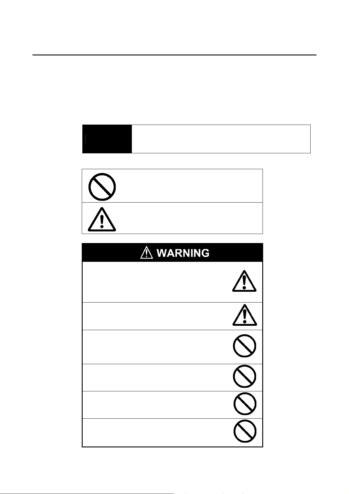
z Line Operating Status Monitor Display
NS-series PTs can be used to display information such as the operating status of the system
and the devices. Graphs and other indicators can be used to better represent the information
and make it easy to understand.
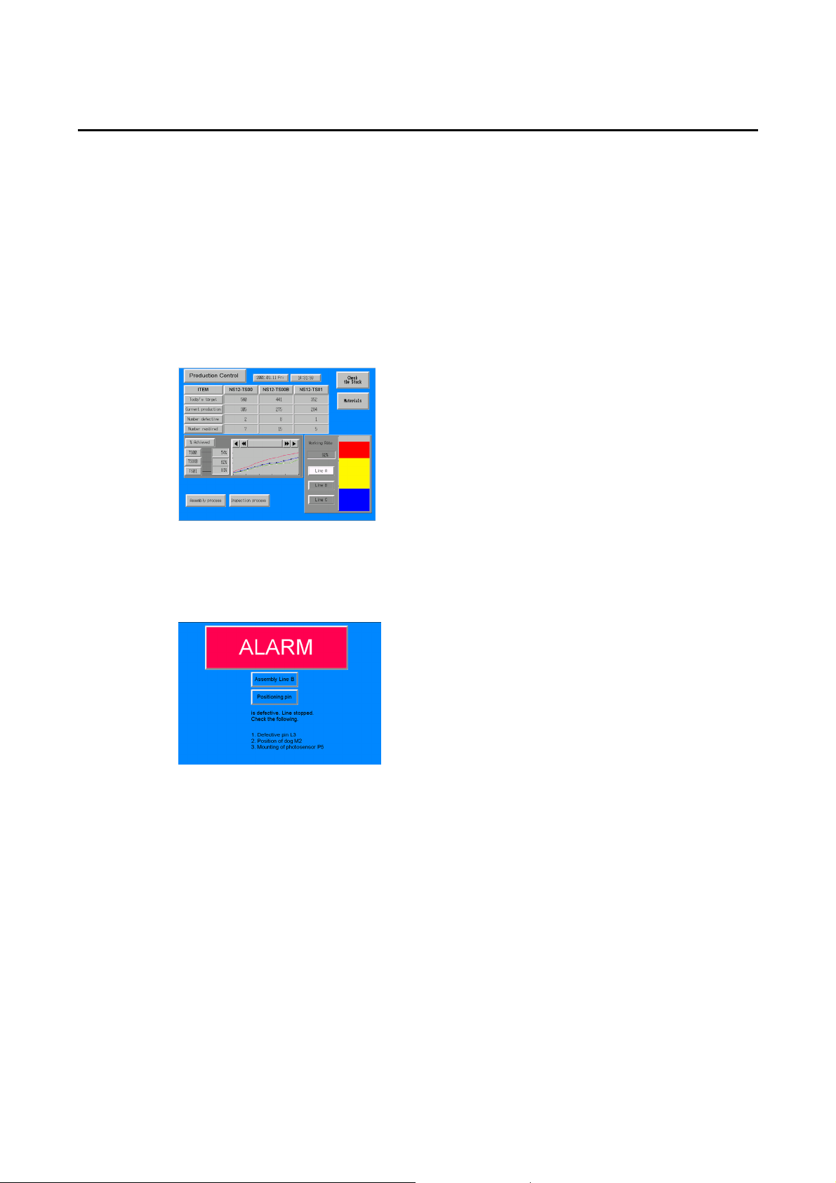
z Directions for FA Site Operators
The PTs can be used to inform the operators of system and device errors and assist them in
taking appropriate measures.
1-2
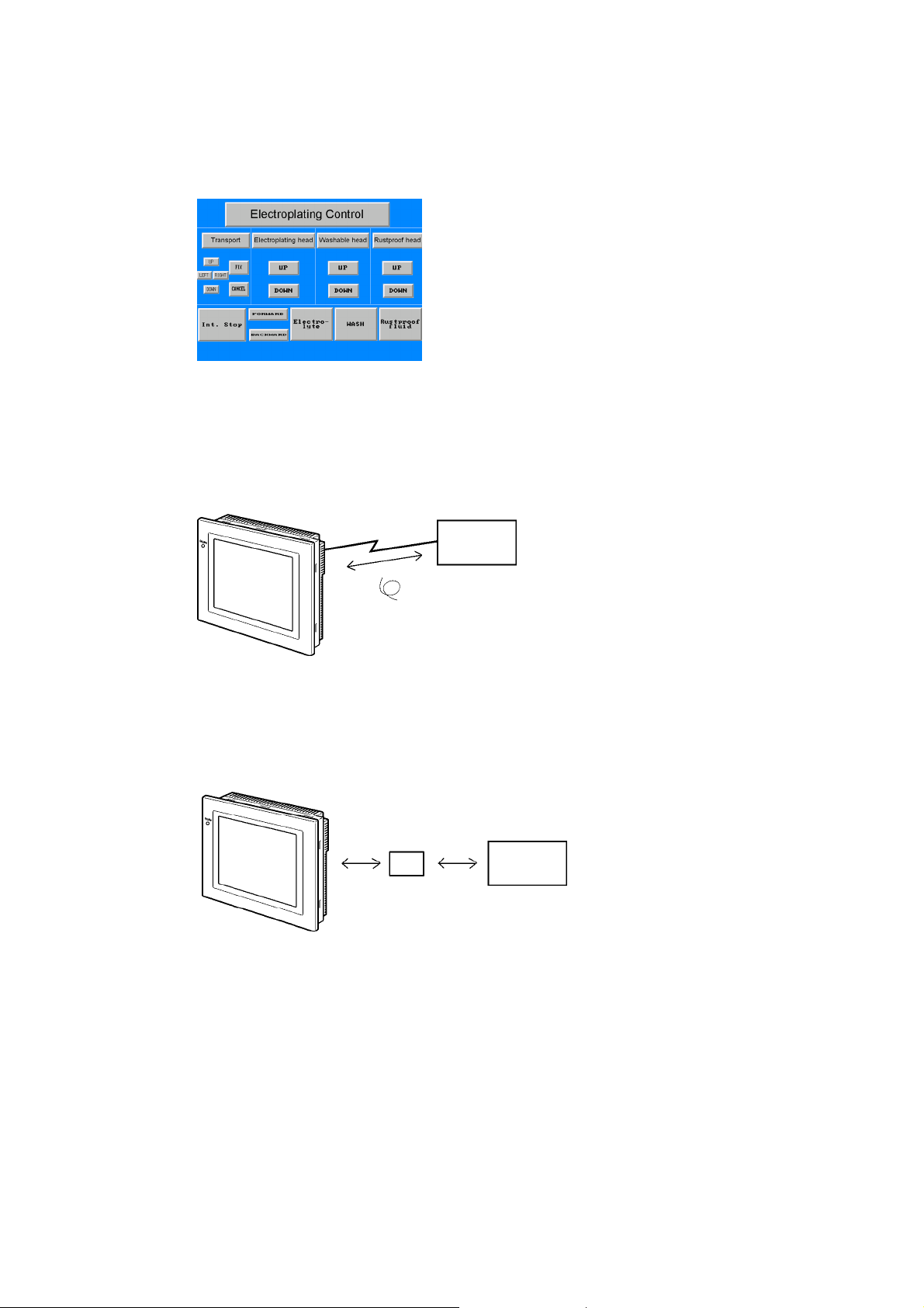
z Control Panel Switches
The NS-series PTs allow the user to create various on-screen switches. By using touch
switch inputs, operating results can be sent to the host.
1-1-2 NS-series PT Operating System
z Transferring Screen Data
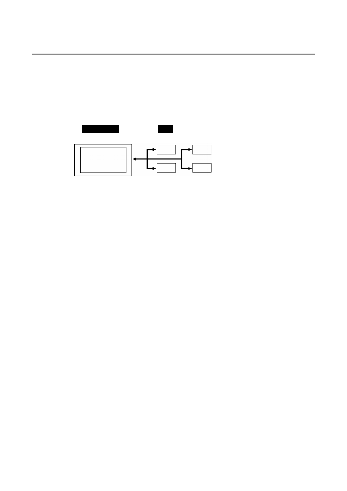
The screen data displayed on NS-series PTs is created using the CX-Designer on a computer and transferred to the PT through RS-232C, Ethernet, or USB communications.
RS-232C, Ethernet,
USB
Create screen data.
Computer
(CX-Designer)
1-1 NS-series PT Functions and Operation
Screen data
Connect the computer to the PT only
when transferring screen data to or from
the CX-Designer.
Note 1: Some models do not support Ethernet.
Note 2: USB data transfer is not supported for some PT lots and system program versions.
Note 3: If the serial port protocol is set to Allen-Bradley DF1, you cannot connect to the CX-Designer
through that port.
Screen data can also be transferred at high speed using a Memory Card.
Memory
Card
Computer
(CX-Designer)
1-3
1-1 NS-series PT Functions and Operation
z Displaying Screens
The information displayed on the screens is created using the CX-Designer on a computer
and transferred to the PT. The required screens can be displayed by using commands from
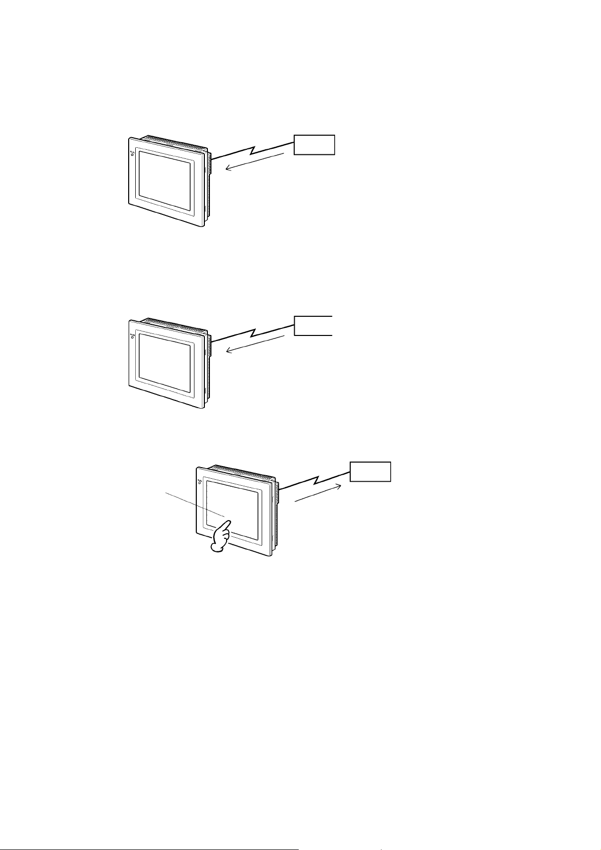
the host or touch switch operations.
z Reading Data from the Host
A communications method such as NT Link Ethernet or Controller Link is used to connect the
host, and the required data is automatically read from the host.
Note: Some models do not support Ethernet or Controller Link.
NT Link or Ethernet,
Controller Link
Host
The required screens can
be displayed by using
commands from the host
or touch switch operations.
Host
z Sending Data to the Host
Data input using touch switches (button ON/OFF status, numerals, and character strings) is
sent to the host.
Host
Touch panel
ON/OFF status,
numeric data, etc.
1-4
1-2 Communications with the Host
NS-series PTs allow the user to allocate words and bits in any PLC area for use in accessing
the required display contents and storing input data.
Operations that can be performed include reading and writing allocated word contents and bit
status directly, changing the display status of functional objects on the PT screen, and controlling and notifying PT status.
The NS-series PTs also enable communications with more than one PLC. A host name is
registered for each PLC connected, allowing access to any PLC areas by specifying the host
name and address.
NS - Series PT
PLC
DM Area I/O Area
1-2 Communications with the Host
Auxiliary Area
Timers/counters
When using NS-series PTs, the host can be connected using any of the following methods.
• 1:1 NT Link
• 1:N NT Link (normal or high-speed)
• Ethernet
• Controller Link
• Host Link
• Other methods, such as temperature controller protocols
• EtherNet/IP
1-5

1-2 Communications with the Host
1-2-1 What is an NT Link?
An NT Link is a method for high-speed communications between an OMRON PLC and an
OMRON Programmable Terminal (PT) using a special protocol. In addition to a 1:1 NT Link,
where a single PT is connected to a single PLC, NS-series PTs also support 1:N NT Links,
allowing up to eight PTs to be connected to a single PLC port.
CS- and CJ-series PLCs can also be connected using high-speed 1:N NT Link communications. For details on the PLCs that support high-speed 1:N NT Link communications, refer to
Appendix 8 Standard Models.
In the rest of this manual, "NT Link" refers to NT Link communications in general, "1:1 NT
Link" refers to an NT Link in a 1:1 configuration only, and "1:N NT Links" refers to NT Links in
a 1:N configuration only. Where necessary, "normal 1:N NT Links" and "high-speed 1:N NT
Links" are used. When "1:N NT Links" is used alone, it refers to both normal and high-speed
communications.
1-2-2 Ethernet
Ethernet Units in PLCs that are supported by the NS-series PTs can be used to read and
write data, word, and bit information simply. The use of FINS (Factory Interface Network Service) message communications, one of OMRON’s standard communications services, enables high-speed communications without the need to be aware of the protocol.
For details on connection methods, refer to Section 5 Connecting to Host via Ethernet or
Controller Link. For details on the PLCs that can be connected to the Ethernet, refer to Ap-
pendix 8 Standard Models.
1-2-3 Controller Link
Controller Link is an FA network that can send and receive large data packets among
OMRON PLCs and FA computers. Controller Link Units for PLCs that are supported by the
NS-series PTs connected to NS-CLK21 Controller Link Interface Units can be used to read
and write data, word, and bit information simply.
The Controller Link supports data links that enable data sharing and a message service that
enables sending and receiving data when required.
For details on connection methods, refer to Section 5 Connecting to Host via Ethernet or
Controller Link. For details on the PLCs that can be connected using Controller Link, refer to
Appendix 8 Standard Models.
Note: Controller Link Interface Units are compatible only with the NS15, NS12, and NS10.
1-2-4 Host Link
Host Link is a serial communications protocol for connecting an OMRON PT 1:1 to a host (a
PLC) to read and write bits and words from the host. Host Link communications connect a PT
to many different PLCs. Refer to the Host Connection Manual (Host Links) for connection
methods and the PLCs for which Host Links can be used.
1-2-5 Connecting to a Temperature Controller
OMRON Temperature Controllers can be connected with an RS-485 connection.
Attach a CJ1W-CIF11 RS-422A Converter to serial port A or B to convert the communications
protocol to RS-485. For details, refer to the Host Connection Manual (Temp. Control, Mem-
Link).
1-6

1-2-6 Memory Link Connections
When the host is a computer instead of a PLC, the Memory Link protocol can be used to
connect with the computer. Use serial port A or B to connect to the host. For details, refer to
the Host Connection Manual (Tem.Control, MemLink).
1-2-7 Communicating with Other Devices
The NS-series PTs can communicate with the following devices.
• OMRON Trajexia Motion Controllers
• Mitsubishi FX-series, A-series, and Q-series PLCs
• Siemens S7-300-series PLCs
• Yaskawa MP-series Machine Controllers
• Yaskawa F7-series Varispeed and VS Mini V7-series Inverters
• Rockwell Automation (Allen-Bradley) SLC500, MicroLogix, PLC-5, CompactLogix,
CompactLogix, and ControlLogix Controllers
• Devices that support Modbus RTU
• Yokogawa Electric FA-M3/FA-M3R-series PLCs
For details on connection methods, refer to the Host Connection Manual (Multivendor Connection).
1-2 Communications with the Host
1-2-8 EtherNet/IP
EtherNet/IP is a multi-vendor industrial network protocol that uses Ethernet. The specification is an open standard managed by the ODVA (Open DeviceNet Vendor Association), as is
DeviceNet, and it is used for a variety of industrial devices.
NS-series PTs can communicate with CS/CJ-series EtherNet/IP Units and
CJ2H-CPU@@-EIP or CJ2M-CPU3@ CPU Units. (The CJ2H-CPU@@-EIP and
CJ2M-CPU3@ have built-in EtherNet/IP ports.)
Also, it is possible to perform tag message communications when using a CPU Unit with a
built-in EtherNet/IP port. These CPU Units contain a tag name server, so if tag names and an
address table are stored in advance in the CPU Unit, it is possible to perform access from the
NS-series PT using only the tag names.
1-7
1-3 System Configuration
r
1-3 System Configuration
The following information describes the system configuration using NS-series PTs. Refer to
Appendix 8 Standard Models for details on available models.
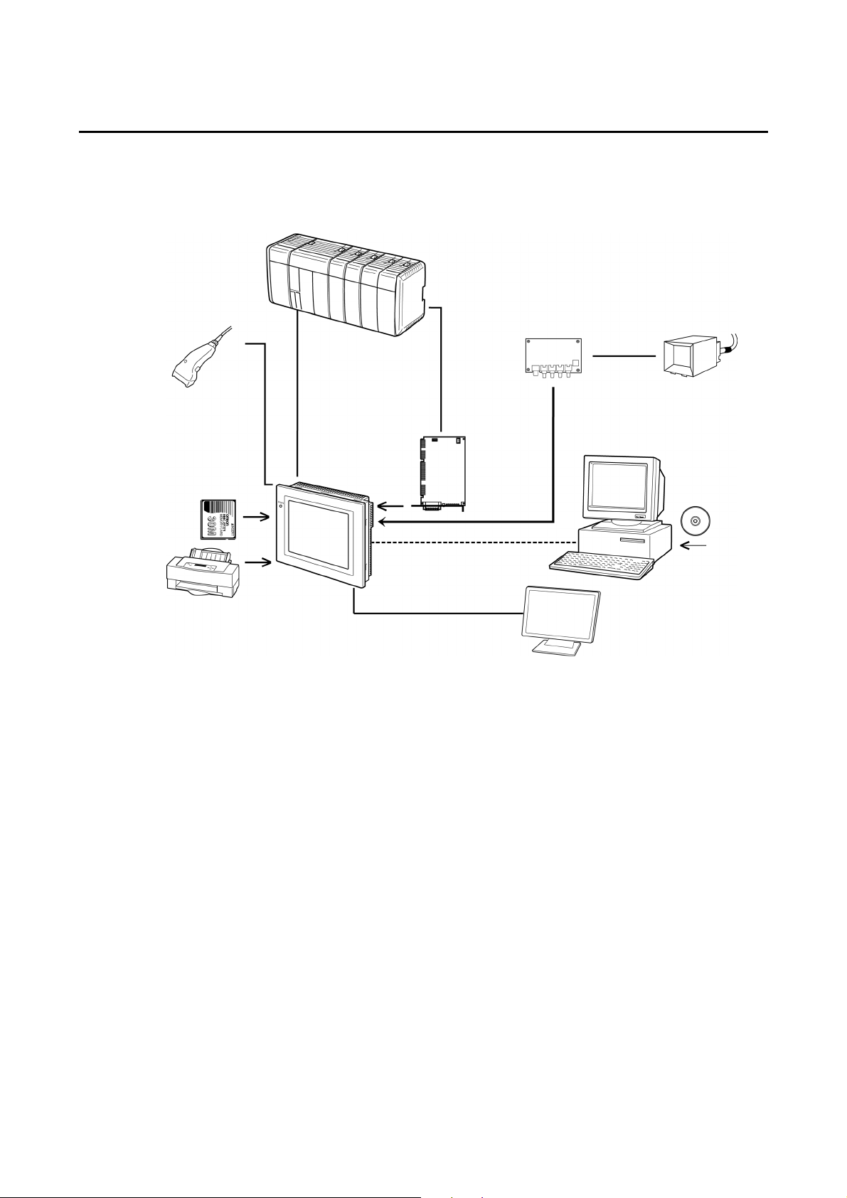
1-3-1 Supported Peripheral Devices
Host
Bar Code Reader
Read bar codes as
text string data.
Memory Card
Save screen data or
the system program or
automatically read data
at startup.
Printer (See note 4.)
Connecting a general-purpose colo
printer to the USB port on an
NS-series PT makes it possible to
print out the current PT display.
NS-series PT
RS-232C cable (15 m max.)
RS-422A cable (500 m max.)
RS-232C/422A Adapter
Ethernet cable (See note 1.)
Twisted-pair cable
Controller Link
Interface Unit
Enables
Controller Link
communications
with a host.
(See note 2.)
RS-232C cable
Ethernet cable
(See note 1.)
USB cable
(See note 5.)
VGA c abl e
Monitor (See note 6.)
Video Input Unit
(See note 3.)
NTSC/PAL cable
Personal computer
Computer running Windows
Video camera or
Vision Sensor
CX-Designer
Note 1: Only the following models support Ethernet: NS15-TX01@-V2, NS12-TS01(B)-V@,
NS10-TV01(B)-V@, NS8-TV@1(B)-V@, NS5-SQ@1(B)-V@, NS5-TQ@1(B)-V@, and
VS5-MQ@1(B)-V@.
Note 2: Only the following models support the Controller Link Interface Unit: NS15-TX01@-V2,
NS12-TS0@, NS10-TV0@. (The NS8 and NS5 do not support the Controller Link Interface
Unit.)
Note 3: The following models support Video Input Units: NS15-TX01@-V2, NS12-TS0@, NS10-TV0@,
and NS8-TV@@. (The NS15-TX01-V2 does not support the NS-CA001 and it does not support
video input from the NS-CA002. It does support analog RGB input from the NS-CA002.) (The
NS5 does not support Video Input Units.)
Note 4: The NS5-SQ0@(B)-V@, NS5-TQ0@(B)-V@, and NS5-MQ0@(B)-V@ cannot be connected di-
rectly to general-purpose printers.
Note 5: Refer to 3-3-2 Connecting via USB for information on connecting the PT and computer with a
USB cable.
A USB Relay Cable can be used to place a USB slave connector on the front of the control
panel. Refer to 3-1-3 Mounting the PT to the Control Panel.
Note 6: Only the following monitor is supported: NS15-TX01@-V2.
• PTs (Refer to Appendix 8 Standard Models.)
• Recommended Bar Code Reader (Refer to page 3-15.)
OMRON V520-RH21-6
OMRON V400-H111
OMRON V400-H211
1-8
Loading...