


SGLGW
YA S K A WA
YASKAWA
YASKAWA
MANUAL NO. SIEP S800000 19C
USER'S MANUAL
SGLGW/SGLFW/SGLTW Linear Servomotors
SGDH SERVOPACK
Linear Series SGL□□/SGDH

Copyright © 2003 YASKAWA ELECTRIC CORPORATION
All rights reserved. No part of this publication may be reproduced, stored in a retrieval system,
or transmitted, in any form, or by any means, mechanical, electronic, photocopying, recording,
or otherwise, without the prior written permission of Yaskawa. No patent liability is assumed
with respect to the use of the information contained herein. Moreover, because Yaskawa is con-
stantly striving to improve its high-quality products, the information contained in this manual is
subject to change without notice. Every precaution has been taken in the preparation of this
manual. Nevertheless, Yaskawa assumes no responsibility for errors or omissions. Neither is
any liability assumed for damages resulting from the use of the information contained in this
publication.

iii
About this Manual
Intended Audience
This manual is intended for the following users.
•
Those selecting Σ
-
II Series servodrives or peripheral devices for Σ
-
II Series servodrives.
•
Those wanting to know about the ratings and characteristics of Σ
-
II Series servodrives.
•
Those
designing
Σ
-
II
Series servodrive systems.
•
Those installing or wiring Σ
-
II Series servodrives.
•
Those performing trial operation or adjustments of Σ
-
II Series servodrives.
•
Those maintaining or inspecting Σ
-
II Series servodrives.
Description of Technical Terms
The terms in this manual are defined as follows:
• Servomotor or motor =
Linear
Σ
Series SGLGW, SGLFW and SGLTW linear servomotor
• SERVOPACK =
Σ
-
II
Series SGDH amplifier.
• Servodrive = A set including a servomotor and servo amplifier.
• Servo System = A servo control system that includes the combination of a servodrive with a host
computer and peripheral devices.
• Parameter number = Numbers that the user inputs toward the SERVOPACK.
Indication of Reverse Signals
In this manual, the names of reverse signals (ones that are valid when low) are written with a forward slash (/)
before the signal name, as shown in the following example:
• S-ON
=
/S-ON
• P-CON
=
/P-CON

iv
Quick access to your required information
Read the chapters marked with 9 to get the information required for your purpose.
■
Visual Aids
The following aids are used to indicate certain types of information for easier reference.
• Indicates important information that should be memorized, including precautions such as alarm dis-
plays to avoid damaging the devices.
• Indicates supplemental information.
• Indicates application examples.
• Indicates definitions of difficult terms or terms that have not been previously explained in this man-
ual.
Chapter
SERVOPACK
s, Linear
Servomotors,
and Peripheral
Devices
Ratings and
Characteristics
System
Design
Panel
Configuration
and Wiring
Trial
Operation
and Servo
Adjustment
Inspection
and
Maintenance
Chapter 1
Outline
9
Chapter 2
Selections
9
Chapter 3
Linear Servomotor
Specifications and
Dimensional Drawings
9999
Chapter 4
SERVOPACK Specifications
and Dimensional Drawings
9999
Chapter 5
Serial Converter Unit
Specifications and Drawings
9999
Chapter 6
Specifications and Drawings
of Cables and Peripheral
Devices
9999
Chapter 7
Installation and Wiring
99 9
Chapter 8
Panel Operator
99
Chapter 9
Operation
9
Chapter 10
Adjustment
9
Chapter 11
Inspection, Maintenance, and
Troubleshooting
9
Chapter 12
Appendix
9999
IMPORTANT
INFO
EXAMPLE
TERMS

v
Related Manuals
Refer to the following manuals as required.
Manual Name Manual Number Contents
Σ
-II Series
AC SERVOPACK SGDH/SGDM
SAFETY PRECAUTIONS
TOBPS80000004 Describes the safety precautions on using a
SERVOPACK in the
Σ
-
II Series.
Σ
-II Series SGM
H/SGDM
Digital Operator Operation Manual
TOE-S800-34 Provides detailed information on the operating method
of the JUSP-OP02A-2 digital operator (option).
Σ
-II Series SERVOPACKs
Personal Computer Monitoring Software
Operation Manual
SIE-S800-35 Describes the using and the operating methods on soft-
ware that changes the local personal computer into the
monitor equipment for the
Σ
-II Series servomotor.
Σ
-II Series SGDH MECHATROLINK
Interface Unit User’s Manual
Model: JUSP-NS100
SIE-C718-4 Provides detailed information on MECHATROLINK
communications.
Σ
-II Series SGDH MECHATROLINK-II
Application Module User’s Manual
Model: JUSP-NS115
SIEPC71080001 Provides detailed information on MECHATROLINK-II
communications.
Σ
-II Series SGDH
DeviceNet Interface Unit
User’s Manual
Model: JUSP-NS300
SIE-C718-6 Describes the DeviceNet communications.
Σ
-II Series SGDH PROFIBUS-DP
IF UNIT User’s Manual
Model: JUSP-NS500
SIE-C718-8 Describes the PROFIBUS-DP communications.
Σ
-II Series Indexer Application Module
User’s Manual
Model: JUSP-NS600
SIE-C718-9 Provides detailed information on positioning by com-
munications and the contact points.
vi
Safety Information
The following conventions are used to indicate precautions in this manual. Failure to heed precautions provided
in this manual can result in serious or possibly even fatal injury or damage to the products or to related equipment
and systems.
Indicates precautions that, if not heeded, could possibly result in loss of life or serious
injury.
Indicates precautions that, if not heeded, could result in relatively serious or minor
injury, damage to the product, or faulty operation.
In some situations, the precautions indicated could have serious consequences if not heeded.
Indicates prohibited actions that must not be performed. For example, this symbol
would be used as follows to indicate that fire is prohibited: .
Indicates compulsory actions that must be performed. For example, this symbol would
be used as follows to indicate that grounding is compulsory: .
The warning symbols for ISO and JIS standards are different, as shown below.
The ISO symbol is used in this manual.
Both of these symbols appear on warning labels on Yaskawa products. Please abide by these warning labels
regardless of which symbol is used.
ISO JIS
WARNING
CAUTION
PROHIBITED
MANDATORY
vii
Notes for Safe Operation
Read this manual thoroughly before checking products on delivery, storage and transportation, installation,
wiring, operation and inspection, and disposal of the AC servodrive.
• If you have a pacemaker or any other electronic medical device, do not go near the magnetic
way of the linear servomotor.
Failure to observe this warning may result in the malfunction of the medical device.
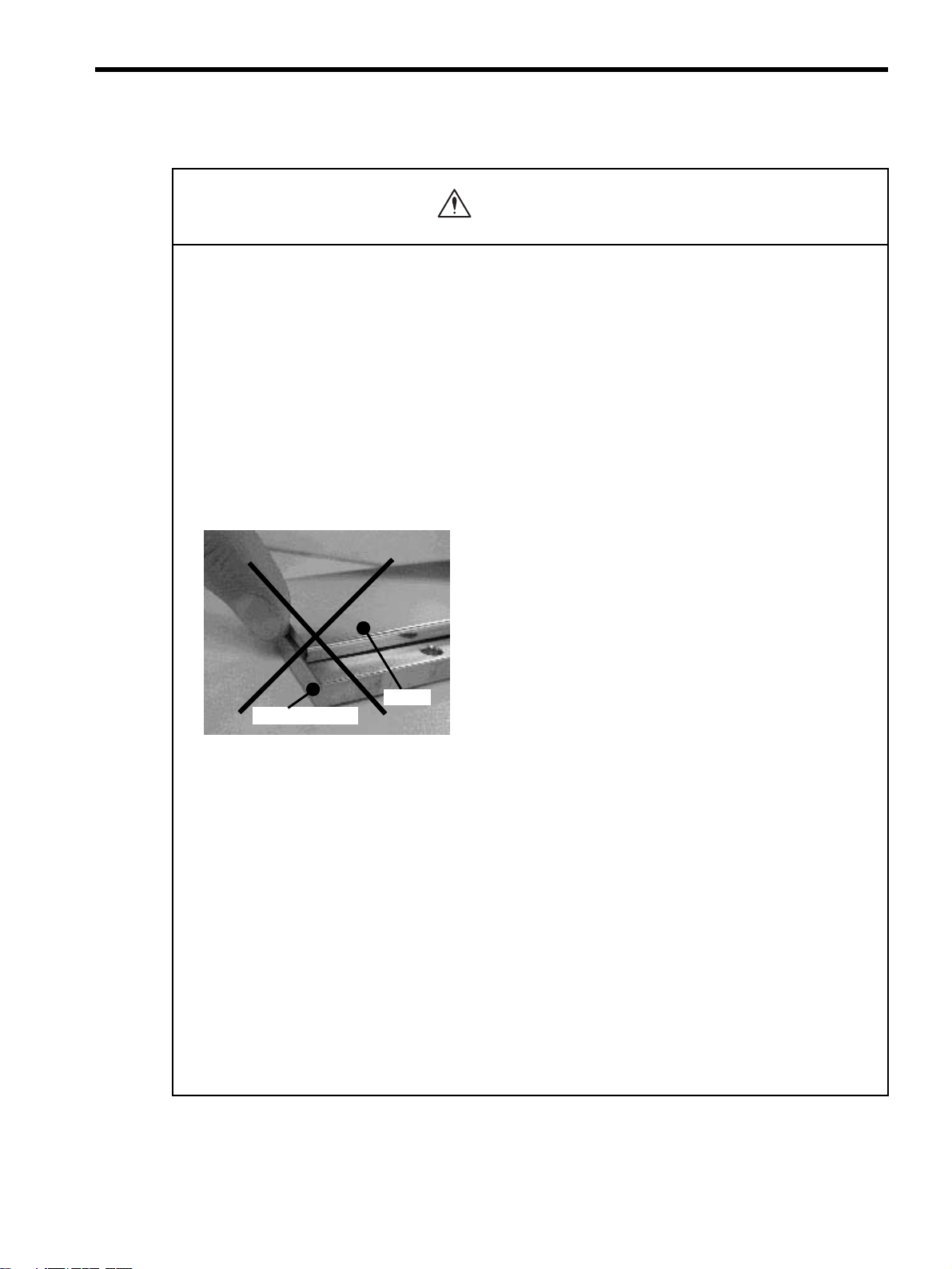
• Be sure to use nonmagnetic tools when installing or working close to the linear servomotor.
(Example: a beryllium-copper alloy hexagonal wrench set, made by NGK Insulators, Ltd.)
• If starting an operation with the linear servomotor in a machine, set the linear servomotor to
always allow emergency stops.
Failure to observe this warning may result in injury.
• Never touch the linear servomotor or machinery during operation.
Failure to observe this warning may result in injury.
• Before wiring, install the SERVOPACK and the linear servomotor.
Failure to observe this warning may result in electric shock.
• Do not operate switches with wet hands.
Failure to observe this warning may result in electric shock.
• Never touch the inside of the SERVOPACKs.
Failure to observe this warning may result in electric shock.
• Do not touch terminals for five minutes after the power is turned OFF.
Residual voltage may cause electric shock.
• Do not touch terminals for five minutes after voltage resistance test.
Residual voltage may cause electric shock.
• Make sure that the main circuit power cable, the control power cable, and the linear
servomotor main circuit cable are wired correctly.
Failure to observe this warning may result in damage to the SERVOPACK.
• Follow the procedures and instructions for trial operation precisely as described in this man-
ual.
Malfunctions that occur after the servomotor is connected to the equipment not only damage the
equipment, but may also cause an accident resulting in death or injury.
• The SGDH SERVOPACK supports both AC and DC power. If DC power is supplied to the
SERVOPACK without setting Pn001=n.
1
(DC power input), the internal components
of the SERVOPACK will burn and may result in fire or serious damage.
Before using a DC power supply, be sure to check the parameter Pn001 setting.
• Do not remove the front cover, cables, connectors, or optional items while the power is ON.
Failure to observe this warning may result in electric shock.
• Do not damage, press, exert excessive force or place heavy objects on the cables.
Failure to observe this warning may result in electric shock, stopping operation of the product, or
burning.
WARNING
viii
Checking on Delivery
Storage and Transportation
• Provide an appropriate stopping device on the machine side to ensure safety.
Failure to observe this warning may result in injury.
• Do not come close to the machine immediately after resetting momentary power loss to avoid an
unexpected restart. Take appropriate measures to ensure safety against an unexpected restart.
Failure to observe this warning may result in injury.
• Connect the ground terminal to electrical codes (ground resistance: 100
Ω
or less).
Improper grounding may result in electric shock or fire.
• Installation, disassembly, or repair must be performed only by authorized personnel.
Failure to observe this warning may result in electric shock or injury.
• Do not modify the product.
Failure to observe this warning may result in injury or damage to the product.
• Always use the linear servomotor and SERVOPACK in one of the specified combinations.
Failure to observe this caution may result in fire or malfunction.
• Be sure to store the magnetic way of the linear servomotor in the same way as it was originally packaged.
• Do not store or install the product in the following places.
• Locations subject to direct sunlight.
• Locations subject to temperatures outside the range specified in the storage or installation temperature conditions.
• Locations subject to humidity outside the range specified in the storage or installation humidity conditions.
• Locations subject to condensation as the result of extreme changes in temperature.
• Locations subject to corrosive or flammable gases.
• Locations subject to dust, salts, or iron dust.
• Locations subject to exposure to water, oil, or chemicals.
• Locations subject to shock or vibration.
Failure to observe this caution may result in fire, electric shock, or damage to the product.
• Do not carry the linear servomotor by its cables.
Failure to observe this caution may result in injury or malfunction.
• Do not place any load exceeding the limit specified on the packing box.
Failure to observe this caution may result in injury or malfunction.
WARNING
CAUTION
CAUTION
ix
Installation
• When unpacking and installing magnetic way, check that no metal fragments or magnetized objects near
the stator because they may be affected by the magnetic attraction of the magnetic way.
Failure to observe this caution may result in injury or damage to the magnetic way's magnets.
• Do not use the magnetic way near metal or other magnetized objects.
Failure to observe this caution may result in injury.
• Do not place clocks, magnetic cards, floppy disks, or measuring instruments close to the magnetic way.
Failure to observe this caution may result in malfunction or damage to these items by the magnetic force.
• Securely mount the linear servomotor on to the machine.
If the linear servomotor is not mounted securely, it may loosen during operation.
• Do not carry the magnetic way by its antimagnetic cover.
Failure to observe this caution may result in injury by the cover’s edge or the shape of the cover may become dis-
torted.
• Install SERVOPACKs, linear servomotors, and regenerative resistors on nonflammable objects.
Mounting directly onto or near flammable objects may result in fire.
• Never use the products in an environment subject to water, corrosive gases, inflammable gases, or
combustibles.
Failure to observe this caution may result in electric shock or fire.
• Do not step on or place a heavy object on the product.
Failure to observe this caution may result in injury.
• Do not cover the inlet or outlet parts and prevent any foreign objects from entering the product.
Failure to observe this caution may cause internal elements to deteriorate resulting in malfunction or fire.
• Be sure to install the product in the correct direction.
Failure to observe this caution may result in malfunction.
• Provide the specified clearances between the SERVOPACK and the control panel or with other devices.
Failure to observe this caution may result in fire or malfunction.
• Do not apply any strong impact.
Failure to observe this caution may result in malfunction.
CAUTION
Cover
Magnetic way
x
Wiring
• Securely tighten the cable connector screws and securing mechanism.
If the connector screws and securing mechanism are not secure, they may loosen during operation.
• Use power lines and cables with a radius, heat resistance, and flexibility suitable for the system.
• If the SERVOPACK malfunctions, turn OFF the main circuit’s power supply of the SERVOPACK.
The continuous flow of a large current may cause fire.
• Use a noise filter to minimize the effects of electromagnetic damage.
Failure to observe this caution may result in electromagnetic damage to electronic devices used near the
SERVOPACK.
• Do not connect a three-phase power supply to the U, V, or W output terminals.
Failure to observe this caution may result in injury or fire.
• Securely connect the power supply terminals and motor output terminals.
Failure to observe this caution may result in fire.
• Do not bundle or run power and signal lines together in the same duct. Keep power and signal lines
separated by at least 30 cm (11.81 in).
Failure to observe this caution may result in malfunction.
• Use shielded twisted-pair wire or shielded multi-core twisted-pair wire for the signal lines and feedback lines
of the serial converter unit (SC).
The maximum wiring length is 3 m for the reference input line and 20 m for the SC feedback line.
• Do not touch the power terminals for five minutes after turning power OFF because high voltage may still
remain in the SERVOPACK.
Make sure the charge indicator is turned OFF first before starting an inspection.
• Avoid frequently turning power ON and OFF. Do not turn power ON or OFF more than once per minute.
Since the SERVOPACK has a capacitor in the power supply, a high charging current flows for 0.2 seconds when
power is turned ON. Frequently turning power ON and OFF causes main power devices such as capacitors and fuses
to deteriorate, resulting in unexpected problems.
• Observe the following precautions when wiring main circuit terminal blocks.
• Remove the terminal block from the SERVOPACK prior to wiring.
• Insert only one wire per terminal on the terminal block.
• Make sure that the core wire is not electrically shorted to adjacent core wires.
• Do not connect the SERVOPACK for 100 V and 200 V directly to a voltage of 400 V.
The SERVOPACK will be destroyed.
• Be sure to wire correctly and securely.
Failure to observe this caution may result in motor overrun, injury, or malfunction.
• Always use the specified power supply voltage.
An incorrect voltage may result in burning.
• Make sure that the polarity is correct.
Incorrect polarity may cause ruptures or damage.
• Take appropriate measures to ensure that the input power supply is supplied within the specified voltage
fluctuation range. Be particularly careful in places where the power supply is unstable.
An incorrect power supply may result in damage to the product.
CAUTION
xi
Operation
• Install external breakers or other safety devices against short-circuiting in external wiring.
Failure to observe this caution may result in fire.
• Take appropriate and sufficient countermeasures for each when installing systems in the following
locations.
• Locations subject to static electricity or other forms of noise.
• Locations subject to strong electromagnetic fields and magnetic fields.
• Locations subject to possible exposure to radioactivity.
• Locations close to power supplies including power supply lines.
Failure to observe this caution may result in damage to the product.
CAUTION
• Do not stand within the machine's range of motion during operation.
Failure to observe this caution may result in injury.
• Before operation, install a limit switch or stopper on the end of the slider to prevent unexpected movement.
Failure to observe this caution may result in injury.
• Before starting operation with a machine connected, change the settings to match the parameters of the
machine.
Starting operation without matching the proper settings may cause the machine to run out of control or malfunction.
• Forward run prohibited (P-OT) and reverse run prohibited (N-OT) signals are not effective during zero point
search mode using parameter Fn003.
• If using the linear servomotor on a vertical axis, install a safety device such as a counterbalance so that the
workpiece does not fall if an alarm or overtravel occurs. Set the linear servomotor so that it will stop in the
zero clamp state at occurrence of overtravel.
The workpiece may fall during overtraveling.
• When not using the online autotuning, set to the correct mass ratio.
Setting to an incorrect moment of inertia ratio may cause vibration.
• Do not touch the SERVOPACK heatsinks, regenerative resistor, or servomotor while power is ON or soon
after the power is turned OFF.
Failure to observe this caution may result in burns due to high temperatures.
• Do not make any extreme adjustments or setting changes of parameters.
Failure to observe this caution may result in injury due to unstable operation.
• When an alarm occurs, remove the cause, reset the alarm after confirming safety, and then resume
operation.
Failure to observe this caution may result in injury.
CAUTION
xii
Maintenance and Inspection
Disposal
General Precautions
• When replacing the SERVOPACK, transfer the previous SERVOPACK parameters to the new
SERVOPACK before resuming operation.
Failure to observe this caution may result in damage to the product.
• Do not attempt to change wiring while the power is ON.
Failure to observe this caution may result in electric shock or injury.
• Do not disassemble the linear servomotor.
Failure to observe this caution may result in electric shock or injury.
• When disposing of the products, treat them as ordinary industrial waste.
Note the following to ensure safe application.
• The drawings presented in this manual are sometimes shown without covers or protective guards. Always replace
the cover or protective guard as specified first, and then operate the products in accordance with the manual.
• The drawings presented in this manual are typical examples and may not match the product you received.
• This manual is subject to change due to product improvement, specification modification, and manual
improvement. When this manual is revised, the manual code is updated and the new manual is published as a next
edition.
• If the manual must be ordered due to loss or damage, inform your nearest Yaskawa representative or one of the
offices listed on the back of this manual.
• Yaskawa will not take responsibility for the results of unauthorized modifications of this product. Yaskawa shall
not be liable for any damages or troubles resulting from unauthorized modification.
CAUTION
CAUTION

xiii
CONTENTS
About this Manual - - - - - - - - - - - - - - - - - - - - - - - - - - - - - - - - - - - - - - - - - - - - - - - - - - - - - - - iii
Related Manuals - - - - - - - - - - - - - - - - - - - - - - - - - - - - - - - - - - - - - - - - - - - - - - - - - - - - - - - - v
Safety Information - - - - - - - - - - - - - - - - - - - - - - - - - - - - - - - - - - - - - - - - - - - - - - - - - - - - - - - vi
Notes for Safe Operation - - - - - - - - - - - - - - - - - - - - - - - - - - - - - - - - - - - - - - - - - - - - - - - - - - vii
1 Outline
1.1 Checking Products - - - - - - - - - - - - - - - - - - - - - - - - - - - - - - - - - - - - - - - - - - - - 1-2
1.1.1 Check Items - - - - - - - - - - - - - - - - - - - - - - - - - - - - - - - - - - - - - - - - - - - - - - - - - - - - - - - - - - 1-2
1.1.2 Linear Servomotors - - - - - - - - - - - - - - - - - - - - - - - - - - - - - - - - - - - - - - - - - - - - - - - - - - - - - 1-2
1.1.3 SERVOPACKs - - - - - - - - - - - - - - - - - - - - - - - - - - - - - - - - - - - - - - - - - - - - - - - - - - - - - - - - 1-3
1.1.4 Serial Converter Units - - - - - - - - - - - - - - - - - - - - - - - - - - - - - - - - - - - - - - - - - - - - - - - - - - - 1-4
1.2 Product Part Names - - - - - - - - - - - - - - - - - - - - - - - - - - - - - - - - - - - - - - - - - - - 1-5
1.2.1 Linear Servomotors - - - - - - - - - - - - - - - - - - - - - - - - - - - - - - - - - - - - - - - - - - - - - - - - - - - - - 1-5
1.2.2 SERVOPACKs - - - - - - - - - - - - - - - - - - - - - - - - - - - - - - - - - - - - - - - - - - - - - - - - - - - - - - - - 1-6
1.3 Examples of Servo System Configurations - - - - - - - - - - - - - - - - - - - - - - - - - - - 1-8
1.3.1 Single-phase, 200 V Main Circuit - - - - - - - - - - - - - - - - - - - - - - - - - - - - - - - - - - - - - - - - - - - 1-8
1.3.2 Three-phase, 200 V Main Circuit- - - - - - - - - - - - - - - - - - - - - - - - - - - - - - - - - - - - - - - - - - - - 1-9
1.3.3 Three-phase, 400 V Main Circuit- - - - - - - - - - - - - - - - - - - - - - - - - - - - - - - - - - - - - - - - - - - 1-10
1.4 Applicable Standards - - - - - - - - - - - - - - - - - - - - - - - - - - - - - - - - - - - - - - - - - 1-11
1.4.1 North American Safety Standards (UL, CSA) - - - - - - - - - - - - - - - - - - - - - - - - - - - - - - - - - - 1-11
1.4.2 CE Marking- - - - - - - - - - - - - - - - - - - - - - - - - - - - - - - - - - - - - - - - - - - - - - - - - - - - - - - - - - 1-11
2 Selections
2.1 Linear Servomotor Model Designation - - - - - - - - - - - - - - - - - - - - - - - - - - - - - - 2-2
2.1.1 Coil Assembly - - - - - - - - - - - - - - - - - - - - - - - - - - - - - - - - - - - - - - - - - - - - - - - - - - - - - - - - 2-2
2.1.2 Magnetic Way - - - - - - - - - - - - - - - - - - - - - - - - - - - - - - - - - - - - - - - - - - - - - - - - - - - - - - - - 2-2
2.2 SERVOPACK Model Designation - - - - - - - - - - - - - - - - - - - - - - - - - - - - - - - - - - 2-3
2.3 Σ-II Series SERVOPACKs and Applicable Linear Servomotors
- - - - - - - - - - - - 2-4
2.4 Serial Converter Units Models - - - - - - - - - - - - - - - - - - - - - - - - - - - - - - - - - - - - 2-6
2.5 Selecting Cables - - - - - - - - - - - - - - - - - - - - - - - - - - - - - - - - - - - - - - - - - - - - - 2-7
2.6 Selecting Peripheral Devices - - - - - - - - - - - - - - - - - - - - - - - - - - - - - - - - - - - - - 2-9
2.6.1 Special Options- - - - - - - - - - - - - - - - - - - - - - - - - - - - - - - - - - - - - - - - - - - - - - - - - - - - - - - - 2-9
2.6.2 Molded-case Circuit Breaker and Fuse Capacity - - - - - - - - - - - - - - - - - - - - - - - - - - - - - - - 2-11
2.6.3 Noise Filters, Magnetic Contactors, Surge Suppressors and DC Reactors - - - - - - - - - - - - - 2-12
2.6.4 Regenerative Resistors - - - - - - - - - - - - - - - - - - - - - - - - - - - - - - - - - - - - - - - - - - - - - - - - - 2-13
2.6.5 Linear Scales - - - - - - - - - - - - - - - - - - - - - - - - - - - - - - - - - - - - - - - - - - - - - - - - - - - - - - - - 2-14

xiv
3 Specifications and Dimensional Drawings
3.1 Ratings and Specifications of SGLGW/SGLGM- - - - - - - - - - - - - - - - - - - - - - - - 3-2
3.2 Ratings and Specifications of SGLFW/SGLFM - - - - - - - - - - - - - - - - - - - - - - - - 3-6
3.3 Ratings and Specifications of SGLTW/SGLTM- - - - - - - - - - - - - - - - - - - - - - - - - 3-9
3.4 Mechanical Specifications of Linear Servomotors - - - - - - - - - - - - - - - - - - - - - 3-15
3.5 Quick Guide to Linear Servomotor Dimensional Drawings - - - - - - - - - - - - - - - 3-16
3.6 Dimensional Drawings of SGLGW/SGLGM Linear Servomotors - - - - - - - - - - - 3-17
3.6.1 SGLG-30 Linear Servomotors- - - - - - - - - - - - - - - - - - - - - - - - - - - - - - - - - - - - - - - - - - - - 3-17
3.6.2 SGLG-40 Linear Servomotors- - - - - - - - - - - - - - - - - - - - - - - - - - - - - - - - - - - - - - - - - - - - 3-20
3.6.3 SGLG-60 Linear Servomotors- - - - - - - - - - - - - - - - - - - - - - - - - - - - - - - - - - - - - - - - - - - - 3-24
3.6.4 SGLG-90 Linear Servomotors- - - - - - - - - - - - - - - - - - - - - - - - - - - - - - - - - - - - - - - - - - - - 3-28
3.7 Dimensional Drawings of SGLFW/SGLFM Linear Servomotors - - - - - - - - - - - 3-30
3.7.1 SGLF-20 Linear Servomotors - - - - - - - - - - - - - - - - - - - - - - - - - - - - - - - - - - - - - - - - - - - - 3-30
3.7.2 SGLF-35 Linear Servomotors - - - - - - - - - - - - - - - - - - - - - - - - - - - - - - - - - - - - - - - - - - - - 3-32
3.7.3 SGLF-50 Linear Servomotors - - - - - - - - - - - - - - - - - - - - - - - - - - - - - - - - - - - - - - - - - - - - 3-35
3.7.4 SGLF-1Z Linear Servomotors - - - - - - - - - - - - - - - - - - - - - - - - - - - - - - - - - - - - - - - - - - - - 3-38
3.8 Dimensional Drawings of SGLTW / SGLTM Linear Servomotors - - - - - - - - - - - 3-41
3.8.1 SGLT-20 Linear Servomotors - - - - - - - - - - - - - - - - - - - - - - - - - - - - - - - - - - - - - - - - - - - - 3-41
3.8.2 SGLT-35A Linear Servomotors- - - - - - - - - - - - - - - - - - - - - - - - - - - - - - - - - - - - 3-44
3.8.3 SGLT-35H Linear Servomotors- - - - - - - - - - - - - - - - - - - - - - - - - - - - - - - - - - - -3-47
3.8.4 SGLT-40 Linear Servomotors - - - - - - - - - - - - - - - - - - - - - - - - - - - - - - - - - - - - - - - - - - - - 3-50
3.8.5
SGLT
-50
Linear Servomotors - - - - - - - - - - - - - - - - - - - - - - - - - - - - - - - - - - - - - - - - - - - - 3-53
3.8.6 SGLT-80 Linear Servomotors - - - - - - - - - - - - - - - - - - - - - - - - - - - - - - - - - - - - - - - - - - - - 3-56
4 SERVOPACK Specifications and Dimensional Drawings
4.1 SERVOPACK Ratings and Specifications - - - - - - - - - - - - - - - - - - - - - - - - - - - - 4-3
4.1.1 Single-phase/Three-phase 200 V - - - - - - - - - - - - - - - - - - - - - - - - - - - - - - - - - - - - - - - - - - - -4-3
4.1.2 Three-phase 400 V - - - - - - - - - - - - - - - - - - - - - - - - - - - - - - - - - - - - - - - - - - - - - - - - - - - - - -4-3
4.1.3 SERVOPACK Ratings and Specifications - - - - - - - - - - - - - - - - - - - - - - - - - - - - - - - - - - - - - -4-4
4.2 SERVOPACK Installation - - - - - - - - - - - - - - - - - - - - - - - - - - - - - - - - - - - - - - - 4-6
4.3 SERVOPACK Internal Block Diagrams - - - - - - - - - - - - - - - - - - - - - - - - - - - - - - 4-8
4.3.1 Single-phase 200 V, 50 W to 400 W Models - - - - - - - - - - - - - - - - - - - - - - - - - - - - - - - - - - - -4-8
4.3.2 Three-phase 200 V, 500 W to 1.5 kW Models - - - - - - - - - - - - - - - - - - - - - - - - - - - - - - - - - - -4-9
4.3.3 Three-phase 200 V, 2.0 kW to 5.0 kW Models - - - - - - - - - - - - - - - - - - - - - - - - - - - - - - - - - - -4-9
4.3.4 Three-phase 200 V, 7.5 kW Models - - - - - - - - - - - - - - - - - - - - - - - - - - - - - - - - - - - - - - - - -4-10
4.3.5 Three-phase 400 V, 500 W to 3.0 kW Models - - - - - - - - - - - - - - - - - - - - - - - - - - - - - - - - - -4-10
4.3.6 Three-phase 400 V, 5.0 kW Model - - - - - - - - - - - - - - - - - - - - - - - - - - - - - - - - - - - - - - - - - - 4-11
4.3.7 Three-phase 400 V, 7.5 kW Models - - - - - - - - - - - - - - - - - - - - - - - - - - - - - - - - - - - - - - - - - 4-11

xv
4.4 SERVOPACK’s Power Supply Capacities and Power Losses - - - - - - - - - - - - - 4-12
4.5 SERVOPACK Overload Characteristics and Allowable Load Mass - - - - - - - - - 4-13
4.5.1 Overload Characteristics - - - - - - - - - - - - - - - - - - - - - - - - - - - - - - - - - - - - - - - - - - - - - - - - 4-13
4.5.2 Starting Time and Stopping Time- - - - - - - - - - - - - - - - - - - - - - - - - - - - - - - - - - - - - - - - - - - 4-14
4.6 SERVOPACK Dimensional Drawings - - - - - - - - - - - - - - - - - - - - - - - - - - - - - - 4-15
4.7 Dimensional Drawings of Base-mounted SERVOPACK Model - - - - - - - - - - - - 4-16
4.7.1 Single-phase 200 V: 50 W/100 W/200 W (A5AE/01AE/02AE) - - - - - - - - - - - - - - - - - - - - - - 4-16
4.7.2 Single-phase 200 V: 400 W (04AE) - - - - - - - - - - - - - - - - - - - - - - - - - - - - - - - - - - - - - - - - - 4-17
4.7.3 Three-phase 200 V: 500 W/750 W/1.0 kW (05AE/08AE/10AE) - - - - - - - - - - - - - - - - - - - - - 4-18
4.7.4 Three-phase 200 V: 1.5 kW (15AE)
Three-phase 400 V: 500 W/750 W/1.0 kW/1.5 kW (05DE/08DE/10DE/15DE) - - - - - - - - - - - 4-19
4.7.5 Three-phase 200 V: 2.0 kW/3.0 kW (20AE/30AE)
Three-phase 400 V: 2.0 kW/3.0 kW (20DE/30DE) - - - - - - - - - - - - - - - - - - - - - - - - - - - - - - 4-20
4.7.6 Three-phase 200 V: 5.0 kW (50AE)
Three-phase 400 V: 5.0 kW (50DE) - - - - - - - - - - - - - - - - - - - - - - - - - - - - - - - - - - - - - - - - 4-21
4.7.7 Three-phase 200 V: 7.5 kW (75AE)- - - - - - - - - - - - - - - - - - - - - - - - - - - - - - - - - - - - - - - - - 4-22
4.7.8 Three-phase 400 V: 7.5 kW (75DE)- - - - - - - - - - - - - - - - - - - - - - - - - - - - - - - - - - - - - - - - - 4-23
4.8 Dimensional Drawings of Rack-mounted SERVOPACK Model - - - - - - - - - - - - 4-24
4.8.1 Single-phase 200 V: 50 W/100 W/200 W (A5AE-R/01AE-R/ 02AE-R)- - - - - - - - - - - - - - - - - 4-24
4.8.2 Single-phase 200 V: 400 W (04AE-R) - - - - - - - - - - - - - - - - - - - - - - - - - - - - - - - - - - - - - - - 4-25
4.8.3 Three-phase 200 V: 500 W/750 W/1.0 kW (05AE-R/08AE-R/10AE-R) - - - - - - - - - - - - - - - - 4-26
4.8.4 Three-phase 200 V: 1.5 kW (15AE-R)
Three-phase 400 V: 500 W/750 W/1.0 kW/1.5 kW (05DE-R/08DE-R/10DE-R/15DE-R) - - - - 4-27
4.8.5 Three-phase 200 V: 2.0 kW/3.0 kW (20AE-R/30AE-R)
Three-phase 400 V: 2.0 kW/3.0 kW (20DE-R/30DE-R) - - - - - - - - - - - - - - - - - - - - - - - - - - - 4-28
4.8.6 Three-phase 200 V: 5.0 kW (50AE-R)
Three-phase 400 V: 5.0 kW (50DE-R)- - - - - - - - - - - - - - - - - - - - - - - - - - - - - - - - - - - - - - - 4-29
4.9 Dimensional Drawings of Duct-ventilated SERVOPACK Model - - - - - - - - - - - - 4-30
4.9.1 Three-phase 200 V: 7.5 kW (75AE-P) - - - - - - - - - - - - - - - - - - - - - - - - - - - - - - - - - - - - - - - 4-30
4.9.2 Three-phase 400 V: 7.5 kW (75DE-P) - - - - - - - - - - - - - - - - - - - - - - - - - - - - - - - - - - - - - - - 4-31
5 Specifications and Dimensional Drawings of Serial Converter Unit
5.1 Serial Converter Unit Specifications - - - - - - - - - - - - - - - - - - - - - - - - - - - - - - - - 5-2
5.2 Analog Signal Input Timing - - - - - - - - - - - - - - - - - - - - - - - - - - - - - - - - - - - - - - 5-3
5.3 Dimensional Drawings of Serial Converter Unit - - - - - - - - - - - - - - - - - - - - - - - - 5-4
5.3.1 Linear Scale without Cable for Hall Sensor by Heidenhain - - - - - - - - - - - - - - - - - - - - - - - - - 5-4
5.3.2 Linear Scale without Cable for Hall Sensor by Renishaw- - - - - - - - - - - - - - - - - - - - - - - - - - - 5-5
5.3.3 Linear Scale with Cable for Hall Sensor by Heidenhain - - - - - - - - - - - - - - - - - - - - - - - - - - - - 5-6
5.3.4 Linear Scale with Cable for Hall Sensor by Renishaw - - - - - - - - - - - - - - - - - - - - - - - - - - - - - 5-8

xvi
6 Specifications and Dimensional Drawings of Cables and Peripheral Devices
6.1 Linear Servomotor Main Circuit Cables- - - - - - - - - - - - - - - - - - - - - - - - - - - - - - 6-2
6.2 Cables for Connecting Serial Converter Units - - - - - - - - - - - - - - - - - - - - - - - - - 6-8
6.3 Cables for Connecting Linear Scales - - - - - - - - - - - - - - - - - - - - - - - - - - - - - - - 6-9
6.4 Cables for Connecting Hall Sensors - - - - - - - - - - - - - - - - - - - - - - - - - - - - - - - 6-10
6.5 Flexible Cables- - - - - - - - - - - - - - - - - - - - - - - - - - - - - - - - - - - - - - - - - - - - - - 6-11
6.6 SERVOPACK Main Circuit Wire Size - - - - - - - - - - - - - - - - - - - - - - - - - - - - - - 6-13
6.6.1 Cable Types- - - - - - - - - - - - - - - - - - - - - - - - - - - - - - - - - - - - - - - - - - - - - - - - - - - - - - - - - -6-13
6.6.2 Single-phase 200 V - - - - - - - - - - - - - - - - - - - - - - - - - - - - - - - - - - - - - - - - - - - - - - - - - - - -6-14
6.6.3 Three-phase 200 V - - - - - - - - - - - - - - - - - - - - - - - - - - - - - - - - - - - - - - - - - - - - - - - - - - - - -6-14
6.6.4 Three-phase 400 V - - - - - - - - - - - - - - - - - - - - - - - - - - - - - - - - - - - - - - - - - - - - - - - - - - - - -6-15
6.7 I/O Signal Cables for CN1 Connector - - - - - - - - - - - - - - - - - - - - - - - - - - - - - - 6-16
6.7.1 Standard Cables- - - - - - - - - - - - - - - - - - - - - - - - - - - - - - - - - - - - - - - - - - - - - - - - - - - - - - -6-16
6.7.2 Connector Type and Cable Size- - - - - - - - - - - - - - - - - - - - - - - - - - - - - - - - - - - - - - - - - - - - 6-16
6.7.3 Connection Diagram - - - - - - - - - - - - - - - - - - - - - - - - - - - - - - - - - - - - - - - - - - - - - - - - - - - -6-18
6.8 Peripheral Devices - - - - - - - - - - - - - - - - - - - - - - - - - - - - - - - - - - - - - - - - - - - 6-19
6.8.1 Cables for Connecting Personal Computers - - - - - - - - - - - - - - - - - - - - - - - - - - - - - - - - - - -6-19
6.8.2 Digital Operator - - - - - - - - - - - - - - - - - - - - - - - - - - - - - - - - - - - - - - - - - - - - - - - - - - - - - - - 6-19
6.8.3 Cables for Analog Monitor - - - - - - - - - - - - - - - - - - - - - - - - - - - - - - - - - - - - - - - - - - - - - - - -6-20
6.8.4 Connector Terminal Block Converter Unit - - - - - - - - - - - - - - - - - - - - - - - - - - - - - - - - - - - - - 6-21
6.8.5 External Regenerative Resistor - - - - - - - - - - - - - - - - - - - - - - - - - - - - - - - - - - - - - - - - - - - -6-22
6.8.6 Regenerative Resistor- - - - - - - - - - - - - - - - - - - - - - - - - - - - - - - - - - - - - - - - - - - - - - - - - - -6-25
6.8.7 Molded-case Circuit Breaker (MCCB) - - - - - - - - - - - - - - - - - - - - - - - - - - - - - - - - - - - - - - - -6-26
6.8.8 Noise Filter - - - - - - - - - - - - - - - - - - - - - - - - - - - - - - - - - - - - - - - - - - - - - - - - - - - - - - - - - -6-27
6.8.9 Magnetic Contactor- - - - - - - - - - - - - - - - - - - - - - - - - - - - - - - - - - - - - - - - - - - - - - - - - - - - -6-31
6.8.10 Surge Suppressor- - - - - - - - - - - - - - - - - - - - - - - - - - - - - - - - - - - - - - - - - - - - - - - - - - - - -6-35
6.8.11 DC Reactor for Harmonic Suppression - - - - - - - - - - - - - - - - - - - - - - - - - - - - - - - - - - - - - - 6-37
6.8.12 Variable Resistor for Speed and Force Setting- - - - - - - - - - - - - - - - - - - - - - - - - - - - - - - - - 6-39
6.8.13 Encoder Signal Converter Unit - - - - - - - - - - - - - - - - - - - - - - - - - - - - - - - - - - - - - - - - - - - -6-40
6.8.14 MECHATROLINK I/F Unit - - - - - - - - - - - - - - - - - - - - - - - - - - - - - - - - - - - - - - - - - - - - - - -6-41
6.8.15 DeviceNet I/F Unit- - - - - - - - - - - - - - - - - - - - - - - - - - - - - - - - - - - - - - - - - - - - - - - - - - - - -6-42
6.8.16 PROFIBUS-DP I/F Unit - - - - - - - - - - - - - - - - - - - - - - - - - - - - - - - - - - - - - - - - - - - - - - - - - 6-43
6.8.17 INDEXER Module - - - - - - - - - - - - - - - - - - - - - - - - - - - - - - - - - - - - - - - - - - - - - - - - - - - - - 6-45
7 Wiring
7.1 Linear Servomotor Installation - - - - - - - - - - - - - - - - - - - - - - - - - - - - - - - - - - - - 7-2
7.1.1 Introduction - - - - - - - - - - - - - - - - - - - - - - - - - - - - - - - - - - - - - - - - - - - - - - - - - - - - - - - - - - -7-2
7.1.2 SGLGW and SGLGM Linear Servomotors (Coreless Types)- - - - - - - - - - - - - - - - - - - - - - - - -7-3
7.1.3 SGLFW and SGLFM Linear Servomotor (F-shaped with Core) - - - - - - - - - - - - - - - - - - - - - - -7-6
7.1.4 SGLTW and SGLTM Linear Servomotor (T Type with Iron Core) - - - - - - - - - - - - - - - - - - - - -7-10

xvii
7.2 Wiring Main Circuit - - - - - - - - - - - - - - - - - - - - - - - - - - - - - - - - - - - - - - - - - - - 7-15
7.2.1 Names and Functions of Main Circuit Terminals - - - - - - - - - - - - - - - - - - - - - - - - - - - - - - - - 7-15
7.2.2 Wiring Main Circuit Power Supply Connector (Spring Type) - - - - - - - - - - - - - - - - - - - - - - - 7-17
7.2.3 Typical Main Circuit Wiring Examples - - - - - - - - - - - - - - - - - - - - - - - - - - - - - - - - - - - - - - - 7-18
7.3 Wiring Encoders - - - - - - - - - - - - - - - - - - - - - - - - - - - - - - - - - - - - - - - - - - - - - 7-21
7.3.1 Connecting an Encoder (CN2) and Output Signals from the SERVOPACK - - - - - - - - - - - - - 7-21
7.3.2 Encoder Connector (CN2) Terminal Layout - - - - - - - - - - - - - - - - - - - - - - - - - - - - - - - - - - - 7-21
7.4 Examples of I/O Signal Connections- - - - - - - - - - - - - - - - - - - - - - - - - - - - - - - 7-22
7.4.1 Speed Control Mode - - - - - - - - - - - - - - - - - - - - - - - - - - - - - - - - - - - - - - - - - - - - - - - - - - - 7-22
7.4.2 Position Control Mode - - - - - - - - - - - - - - - - - - - - - - - - - - - - - - - - - - - - - - - - - - - - - - - - - - 7-23
7.4.3 Force Control Mode- - - - - - - - - - - - - - - - - - - - - - - - - - - - - - - - - - - - - - - - - - - - - - - - - - - - 7-24
7.4.4 I/O Signal Connector (CN1) Terminal Layout - - - - - - - - - - - - - - - - - - - - - - - - - - - - - - - - - - 7-25
7.4.5 I/O Signal (CN1) Names and Functions - - - - - - - - - - - - - - - - - - - - - - - - - - - - - - - - - - - - - - 7-26
7.4.6 Interface Circuit- - - - - - - - - - - - - - - - - - - - - - - - - - - - - - - - - - - - - - - - - - - - - - - - - - - - - - - 7-28
7.5 Others - - - - - - - - - - - - - - - - - - - - - - - - - - - - - - - - - - - - - - - - - - - - - - - - - - - - 7-31
7.5.1 Wiring Precautions - - - - - - - - - - - - - - - - - - - - - - - - - - - - - - - - - - - - - - - - - - - - - - - - - - - - 7-31
7.5.2 Wiring for Noise Control - - - - - - - - - - - - - - - - - - - - - - - - - - - - - - - - - - - - - - - - - - - - - - - - - 7-32
7.5.3 Using More Than One SERVOPACK- - - - - - - - - - - - - - - - - - - - - - - - - - - - - - - - - - - - - - - - 7-35
7.5.4 Operating Conditions on 400-V Power Supply Voltage - - - - - - - - - - - - - - - - - - - - - - - - - - - 7-36
7.5.5 DC Reactor for Harmonic Suppression - - - - - - - - - - - - - - - - - - - - - - - - - - - - - - - - - - - - - - 7-37
7.6 Connecting Regenerative Resistors - - - - - - - - - - - - - - - - - - - - - - - - - - - - - - - 7-38
7.6.1 Regenerative Power and Regenerative Resistance - - - - - - - - - - - - - - - - - - - - - - - - - - - - - 7-38
7.6.2 Connecting External Regenerative Resistors - - - - - - - - - - - - - - - - - - - - - - - - - - - - - - - - - - 7-38
8 Digital Operator/Panel Operator
8.1 Functions on Digital Operator/Panel Operator - - - - - - - - - - - - - - - - - - - - - - - - - 8-2
8.1.1 Connecting the Digital Operator - - - - - - - - - - - - - - - - - - - - - - - - - - - - - - - - - - - - - - - - - - - 8-2
8.1.2 Key Names and Functions - - - - - - - - - - - - - - - - - - - - - - - - - - - - - - - - - - - - - - - - - - - - - - - 8-3
8.1.3 Basic Mode Selection and Operation- - - - - - - - - - - - - - - - - - - - - - - - - - - - - - - - - - - - - - - - - 8-4
8.1.4 Status Display - - - - - - - - - - - - - - - - - - - - - - - - - - - - - - - - - - - - - - - - - - - - - - - - - - - - - - - - 8-6
8.2 Operation in Utility Function Mode (Fn) - - - - - - - - - - - - - - - - - - - - - - - - - 8-8
8.2.1 List of Utility Function Modes - - - - - - - - - - - - - - - - - - - - - - - - - - - - - - - - - - - - - - - - - - - - - - 8-8
8.2.2 Alarm Traceback Data Display (Fn000) - - - - - - - - - - - - - - - - - - - - - - - - - - - - - - - - - - - - - - - 8-9
8.2.3 JOG Mode Operation (Fn002) - - - - - - - - - - - - - - - - - - - - - - - - - - - - - - - - - - - - - - - - - - - - 8-10
8.2.4 Zero-point Search Mode (Fn003) - - - - - - - - - - - - - - - - - - - - - - - - - - - - - - - - - - - - - - - - - - 8-11
8.2.5 Parameter Settings Initialization (Fn005) - - - - - - - - - - - - - - - - - - - - - - - - - - - - - - - - - - - - - 8-12
8.2.6 Alarm Traceback Data Clear (Fn006) - - - - - - - - - - - - - - - - - - - - - - - - - - - - - - - - - - - - - - - 8-13
8.2.7 Automatic Offset-adjustment of Motor Current Detection Signal (Fn00E) - - - - - - - - - - - - - - 8-14
8.2.8 Manual Offset-adjustment of Motor Current Detection Signal (Fn00F) - - - - - - - - - - - - - - - - 8-15
8.2.9 Password Setting (Protects Parameters from Being Changed) (Fn010) - - - - - - - - - - - - - - - 8-16
8.2.10 Motor Models Display (Fn011) - - - - - - - - - - - - - - - - - - - - - - - - - - - - - - - - - - - - - - - - - - - 8-17
8.2.11 Software Version Display (Fn012) - - - - - - - - - - - - - - - - - - - - - - - - - - - - - - - - - - - - - - - - - 8-18

xviii
8.2.12 Application Module Detection Results Clear (Fn014) - - - - - - - - - - - - - - - - - - - - - - - - - - - - 8-19
8.3 Operation in Parameter Setting Mode (Pn)- - - - - - - - - - - - - - - - - - - - - - 8-20
8.3.1 Setting Parameters - - - - - - - - - - - - - - - - - - - - - - - - - - - - - - - - - - - - - - - - - - - - - - - - - - - - -8-20
8.3.2 Input Circuit Signal Allocation - - - - - - - - - - - - - - - - - - - - - - - - - - - - - - - - - - - - - - - - - - - - -8-24
8.3.3 Output Circuit Signal Allocation - - - - - - - - - - - - - - - - - - - - - - - - - - - - - - - - - - - - - - - - - - - -8-28
8.4 Operation in Monitor Mode (Un) - - - - - - - - - - - - - - - - - - - - - - - - - - - - - 8-30
8.4.1 List of Monitor Modes - - - - - - - - - - - - - - - - - - - - - - - - - - - - - - - - - - - - - - - - - - - - - - - - - - -8-30
8.4.2 Sequence I/O Signal Monitor Display - - - - - - - - - - - - - - - - - - - - - - - - - - - - - - - - - - - - - - - -8-31
8.4.3 Operation in Monitor Mode - - - - - - - - - - - - - - - - - - - - - - - - - - - - - - - - - - - - - - - - - - - - - - - 8-32
8.4.4 Monitor Display of Reference Pulse Counter and Feedback Pulse Counter - - - - - - - - - - - - -8-33
8.4.5 Allowable Maximum Motor Speed for Dividing Ratio Monitor
(For the software version 32 or later) - - - - - - - - - - - - - - - - - - - - - - - - - - - - - - - - - - - - - - - -8-34
8.4.6 Hall Sensor Signal Monitor (For the software version 32 or later) - - - - - - - - - - - - - - - - - - - - 8-35
9 Operation
9.1 Trial Operation - - - - - - - - - - - - - - - - - - - - - - - - - - - - - - - - - - - - - - - - - - - - - - - 9-4
9.2 Trial Operation Using SERVOPACK Internal References - - - - - - - - - - - - - - - - - 9-6
9.2.1 SERVOPACK Setup Procedure - - - - - - - - - - - - - - - - - - - - - - - - - - - - - - - - - - - - - - - - - - - - -9-6
9.2.2 Setup Procedure Using Linear Servomotors with Hall Sensors - - - - - - - - - - - - - - - - - - - - - - -9-6
9.2.3 Setup Procedure Using Linear Servomotors without Hall Sensors - - - - - - - - - - - - - - - - - - - - 9-12
9.3 Trial Operation for Linear Servomotor without Load from Host Reference - - - - 9-22
9.3.1 Servo ON Command from the Host - - - - - - - - - - - - - - - - - - - - - - - - - - - - - - - - - - - - - - - - - 9-22
9.3.2 Operating Procedure in Speed Control Mode (Pn000 = n.0)- - - - - - - - - - - - - - - - - - - -9-24
9.3.3 Operating Procedure in Position Control Mode (Pn000 = n.1) - - - - - - - - - - - - - - - - - -9-26
9.4
Trial Operation with the Linear Servomotor Connected to the Machine
- - - - - - 9-28
9.5 Control Mode Selection- - - - - - - - - - - - - - - - - - - - - - - - - - - - - - - - - - - - - - - - 9-29
9.6 Setting Common Basic Functions - - - - - - - - - - - - - - - - - - - - - - - - - - - - - - - - 9-30
9.6.1 Setting the Servo ON Signal - - - - - - - - - - - - - - - - - - - - - - - - - - - - - - - - - - - - - - - - - - - - - -9-30
9.6.2 Switching the Linear Servomotor Movement Direction - - - - - - - - - - - - - - - - - - - - - - - - - - - -9-31
9.6.3 Setting the Overtravel Limit Function - - - - - - - - - - - - - - - - - - - - - - - - - - - - - - - - - - - - - - - -9-32
9.6.4 Selecting the Stopping Method After Servo OFF - - - - - - - - - - - - - - - - - - - - - - - - - - - - - - - -9-34
9.6.5 Instantaneous Power Loss Settings - - - - - - - - - - - - - - - - - - - - - - - - - - - - - - - - - - - - - - - - - 9-35
9.6.6 Motor Maximum Speed (For the software version 32 or later) - - - - - - - - - - - - - - - - - - - - - - -9-35
9.7 Operating Using Speed Control with Analog Reference - - - - - - - - - - - - - - - - - 9-36
9.7.1 Setting Parameters - - - - - - - - - - - - - - - - - - - - - - - - - - - - - - - - - - - - - - - - - - - - - - - - - - - - -9-36
9.7.2 Setting Input Signals - - - - - - - - - - - - - - - - - - - - - - - - - - - - - - - - - - - - - - - - - - - - - - - - - - - - 9-37
9.7.3 Adjusting Offset - - - - - - - - - - - - - - - - - - - - - - - - - - - - - - - - - - - - - - - - - - - - - - - - - - - - - - - 9-38
9.7.4 Soft Start - - - - - - - - - - - - - - - - - - - - - - - - - - - - - - - - - - - - - - - - - - - - - - - - - - - - - - - - - - - -9-41
9.7.5 Speed Reference Filter - - - - - - - - - - - - - - - - - - - - - - - - - - - - - - - - - - - - - - - - - - - - - - - - - -9-41
9.7.6 Using the Zero Clamp Function - - - - - - - - - - - - - - - - - - - - - - - - - - - - - - - - - - - - - - - - - - - -9-41
9.7.7 Encoder Signal Output - - - - - - - - - - - - - - - - - - - - - - - - - - - - - - - - - - - - - - - - - - - - - - - - - -9-43

xix
9.7.8 Speed Coincidence Output- - - - - - - - - - - - - - - - - - - - - - - - - - - - - - - - - - - - - - - - - - - - - - - 9-46
9.8 Operating Using Position Control - - - - - - - - - - - - - - - - - - - - - - - - - - - - - - - - - 9-47
9.8.1 Setting Parameters - - - - - - - - - - - - - - - - - - - - - - - - - - - - - - - - - - - - - - - - - - - - - - - - - - - - 9-47
9.8.2 Setting the Electronic Gear- - - - - - - - - - - - - - - - - - - - - - - - - - - - - - - - - - - - - - - - - - - - - - - 9-49
9.8.3 Position Reference - - - - - - - - - - - - - - - - - - - - - - - - - - - - - - - - - - - - - - - - - - - - - - - - - - - - 9-52
9.8.4 Smoothing - - - - - - - - - - - - - - - - - - - - - - - - - - - - - - - - - - - - - - - - - - - - - - - - - - - - - - - - - - 9-55
9.8.5 Positioning Completed Output Signal - - - - - - - - - - - - - - - - - - - - - - - - - - - - - - - - - - - - - - - 9-57
9.8.6 Positioning Near Signal - - - - - - - - - - - - - - - - - - - - - - - - - - - - - - - - - - - - - - - - - - - - - - - - - 9-58
9.8.7 Reference Pulse Inhibit Function (INHIBIT) - - - - - - - - - - - - - - - - - - - - - - - - - - - - - - - - - - - 9-59
9.9 Operating Using Force Control- - - - - - - - - - - - - - - - - - - - - - - - - - - - - - - - - - - 9-60
9.9.1 Setting Parameters - - - - - - - - - - - - - - - - - - - - - - - - - - - - - - - - - - - - - - - - - - - - - - - - - - - - 9-60
9.9.2 Force Reference Input - - - - - - - - - - - - - - - - - - - - - - - - - - - - - - - - - - - - - - - - - - - - - - - - - - 9-60
9.9.3 Adjusting the Force Reference Offset - - - - - - - - - - - - - - - - - - - - - - - - - - - - - - - - - - - - - - - 9-61
9.9.4 Limiting Linear Servomotor Speed during Force Control - - - - - - - - - - - - - - - - - - - - - - - - - - 9-63
9.10 Operating Using Speed Control with an Internally Set Speed - - - - - - - - - - - - 9-65
9.10.1 Setting Parameters - - - - - - - - - - - - - - - - - - - - - - - - - - - - - - - - - - - - - - - - - - - - - - - - - - - 9-65
9.10.2 Input Signal Settings - - - - - - - - - - - - - - - - - - - - - - - - - - - - - - - - - - - - - - - - - - - - - - - - - - 9-66
9.10.3 Operating Using an Internally Set Speed - - - - - - - - - - - - - - - - - - - - - - - - - - - - - - - - - - - - 9-66
9.11 Limiting Force - - - - - - - - - - - - - - - - - - - - - - - - - - - - - - - - - - - - - - - - - - - - - - 9-68
9.11.1 Internal Force Limit (Limiting Maximum Output Force)- - - - - - - - - - - - - - - - - - - - - - - - - - - 9-68
9.11.2 External Force Limit (Output Force Limiting by Input Signals)- - - - - - - - - - - - - - - - - - - - - - 9-69
9.11.3 Force Limiting Using an Analog Voltage Reference- - - - - - - - - - - - - - - - - - - - - - - - - - - - - 9-71
9.11.4 Force Limiting Using an External Force Limit and Analog Voltage Reference- - - - - - - - - - - 9-72
9.11.5 Checking Output Force Limiting during Operation - - - - - - - - - - - - - - - - - - - - - - - - - - - - - - 9-73
9.12 Control Mode Selection - - - - - - - - - - - - - - - - - - - - - - - - - - - - - - - - - - - - - - - 9-74
9.12.1 Setting Parameters - - - - - - - - - - - - - - - - - - - - - - - - - - - - - - - - - - - - - - - - - - - - - - - - - - - 9-74
9.12.2 Switching the Control Mode - - - - - - - - - - - - - - - - - - - - - - - - - - - - - - - - - - - - - - - - - - - - - 9-74
9.13 Other Output Signals- - - - - - - - - - - - - - - - - - - - - - - - - - - - - - - - - - - - - - - - - 9-76
9.13.1 Servo Alarm Output (ALM) and Alarm Code Output (ALO1, ALO2, ALO3) - - - - - - - - - - - - 9-76
9.13.2 Warning Output (/WARN) - - - - - - - - - - - - - - - - - - - - - - - - - - - - - - - - - - - - - - - - - - - - - - - 9-77
9.13.3 Running Output Signal (/TGON) - - - - - - - - - - - - - - - - - - - - - - - - - - - - - - - - - - - - - - - - - - 9-77
9.13.4 Servo Ready (/S-RDY) Output - - - - - - - - - - - - - - - - - - - - - - - - - - - - - - - - - - - - - - - - - - - 9-78
10 Adjustments
10.1 Autotuning - - - - - - - - - - - - - - - - - - - - - - - - - - - - - - - - - - - - - - - - - - - - - - - - 10-2
10.1.1 Servo Gain Adjustment Methods - - - - - - - - - - - - - - - - - - - - - - - - - - - - - - - - - - - - - - - - - - 10-2
10.1.2 List of Servo Adjustment Functions - - - - - - - - - - - - - - - - - - - - - - - - - - - - - - - - - - - - - - - - 10-3
10.2 Online Autotuning - - - - - - - - - - - - - - - - - - - - - - - - - - - - - - - - - - - - - - - - - - - 10-5
10.2.1 Online Autotuning - - - - - - - - - - - - - - - - - - - - - - - - - - - - - - - - - - - - - - - - - - - - - - - - - - - - 10-5
10.2.2 Online Autotuning Procedure - - - - - - - - - - - - - - - - - - - - - - - - - - - - - - - - - - - - - - - - - - - - 10-6
10.2.3 Selecting the Online Autotuning Execution Method - - - - - - - - - - - - - - - - - - - - - - - - - - - - - 10-7

xx
10.2.4 Machine Rigidity Setting for Online Autotuning - - - - - - - - - - - - - - - - - - - - - - - - - - - - - - - - 10-8
10.2.5 Method for Changing the Machine Rigidity Setting - - - - - - - - - - - - - - - - - - - - - - - - - - - - - - 10-9
10.2.6 Saving the Results of Online Autotuning - - - - - - - - - - - - - - - - - - - - - - - - - - - - - - - - - - - - 10-10
10.2.7 Procedure for Saving the Results of Online Autotuning- - - - - - - - - - - - - - - - - - - - - - - - - - 10-11
10.3 Manual Tuning - - - - - - - - - - - - - - - - - - - - - - - - - - - - - - - - - - - - - - - - - - - - 10-12
10.3.1 Explanation of Servo Gain - - - - - - - - - - - - - - - - - - - - - - - - - - - - - - - - - - - - - - - - - - - - - - 10-12
10.3.2 Servo Gain Manual Tuning - - - - - - - - - - - - - - - - - - - - - - - - - - - - - - - - - - - - - - - - - - - - - 10-13
10.3.3 Position Loop Gain - - - - - - - - - - - - - - - - - - - - - - - - - - - - - - - - - - - - - - - - - - - - - - - - - - -10-13
10.3.4 Speed Loop Gain - - - - - - - - - - - - - - - - - - - - - - - - - - - - - - - - - - - - - - - - - - - - - - - - - - - - 10-14
10.3.5 Speed Loop Integral Time Constant - - - - - - - - - - - - - - - - - - - - - - - - - - - - - - - - - - - - - - - 10-14
10.4 Servo Gain Adjustment Functions - - - - - - - - - - - - - - - - - - - - - - - - - - - - - - 10-15
10.4.1 Feed-forward Reference - - - - - - - - - - - - - - - - - - - - - - - - - - - - - - - - - - - - - - - - - - - - - - - 10-15
10.4.2 Force Feed-forward - - - - - - - - - - - - - - - - - - - - - - - - - - - - - - - - - - - - - - - - - - - - - - - - - - 10-16
10.4.3 Speed Feed-forward - - - - - - - - - - - - - - - - - - - - - - - - - - - - - - - - - - - - - - - - - - - - - - - - - - 10-17
10.4.4 Proportional Control Operation (Proportional Operation Reference) - - - - - - - - - - - - - - - - - 10-18
10.4.5 Using the Mode Switch (P/PI Switching) - - - - - - - - - - - - - - - - - - - - - - - - - - - - - - - - - - - - 10-19
10.4.6 Setting the Speed Bias - - - - - - - - - - - - - - - - - - - - - - - - - - - - - - - - - - - - - - - - - - - - - - - - 10-22
10.4.7 Speed Feedback Filter - - - - - - - - - - - - - - - - - - - - - - - - - - - - - - - - - - - - - - - - - - - - - - - - 10-22
10.4.8 Speed Feedback Compensation- - - - - - - - - - - - - - - - - - - - - - - - - - - - - - - - - - - - - - - - - - 10-23
10.4.9 Switching Gain Settings- - - - - - - - - - - - - - - - - - - - - - - - - - - - - - - - - - - - - - - - - - - - - - - - 10-25
10.4.10 Force Reference Filter- - - - - - - - - - - - - - - - - - - - - - - - - - - - - - - - - - - - - - - - - - - - - - - - 10-26
10.5 Analog Monitor - - - - - - - - - - - - - - - - - - - - - - - - - - - - - - - - - - - - - - - - - - - - 10-29
11 Inspection, Maintenance, and Troubleshooting
11.1 Troubleshooting - - - - - - - - - - - - - - - - - - - - - - - - - - - - - - - - - - - - - - - - - - - - 11-2
11.1.1 Alarm Display Table- - - - - - - - - - - - - - - - - - - - - - - - - - - - - - - - - - - - - - - - - - - - - - - - - - - - 11-2
11.1.2 Warning Display - - - - - - - - - - - - - - - - - - - - - - - - - - - - - - - - - - - - - - - - - - - - - - - - - - - - - - 11-4
11.1.3 Alarm Display Table when the Application Module is Used - - - - - - - - - - - - - - - - - - - - - - - - 11-5
11.1.4 Warning Display Table when the Application Module is Used - - - - - - - - - - - - - - - - - - - - - - 11-6
11.1.5 Troubleshooting of Alarm and Warning - - - - - - - - - - - - - - - - - - - - - - - - - - - - - - - - - - - - - - 11-7
11.1.6 Troubleshooting for Malfunction without Alarm Display - - - - - - - - - - - - - - - - - - - - - - - - - - 11-17
11.2 Inspection and Maintenance - - - - - - - - - - - - - - - - - - - - - - - - - - - - - - - - - - 11-22
11.2.1 Linear Servomotor Inspection
- - - - - - - - - - - - - - - - - - - - - - - - - - - - - - - - - - - - - - - - - - - - 11-22
11.2.2 SERVOPACK Inspection - - - - - - - - - - - - - - - - - - - - - - - - - - - - - - - - - - - - - - - - - - - - - - - 11-22
11.2.3 Parts Replacement Schedule - - - - - - - - - - - - - - - - - - - - - - - - - - - - - - - - - - - - - - - - - - - - 11-23
12 Appendix
12.1 Linear Servomotor Capacity Selection Examples- - - - - - - - - - - - - - - - - - - - - 12-2
12.2 Calculating the Required Capacity of Regenerative Resistors - - - - - - - - - - - - 12-4
12.2.1 Simple Calculation - - - - - - - - - - - - - - - - - - - - - - - - - - - - - - - - - - - - - - - - - - - - - - - - - - - - 12-4
12.2.2 Calculating the Regenerative Energy - - - - - - - - - - - - - - - - - - - - - - - - - - - - - - - - - - - - - - -12-7

xxi
12.3 Connection to Host Controller - - - - - - - - - - - - - - - - - - - - - - - - - - - - - - - - - 12-16
12.3.1 Example of Connection to MP2200/MP2300 2-axes Motion Module SVA-01 - - - - - - - - - - 12-16
12.3.2 Example of Connection to OMRON’s Motion Control Unit - - - - - - - - - - - - - - - - - - - - - - - 12-17
12.3.3 Example of Connection to OMRON’s Position Control Unit - - - - - - - - - - - - - - - - - - - - - - 12-18
12.3.4 Example of Connection to OMRON’s Position Control Unit C500-NC221
(SERVOPACK in Speed Control Mode) - - - - - - - - - - - - - - - - - - - - - - - - - - - - - - - - - - - - 12-19
12.3.5 Example of Connection to OMRON’s Position Control Unit C500-NC112
(SERVOPACK in Position Control Mode) - - - - - - - - - - - - - - - - - - - - - - - - - - - - - - - - - - - 12-20
12.3.6 Example of Connection to Mitsubishi’s AD72 Positioning Unit
(SERVOPACK in Speed Control Mode) - - - - - - - - - - - - - - - - - - - - - - - - - - - - - - - - - - - - - 12-21
12.3.7 Example of Connection to Mitsubishi’s AD75 Positioning Unit
(SERVOPACK in Position Control Mode)- - - - - - - - - - - - - - - - - - - - - - - - - - - - - - - - - - - - 12-22
12.4 List of Parameters- - - - - - - - - - - - - - - - - - - - - - - - - - - - - - - - - - - - - - - - - - 12-23
12.4.1 Utility Functions List - - - - - - - - - - - - - - - - - - - - - - - - - - - - - - - - - - - - - - - - - - - - - - - - - - 12-23
12.4.2 List of Parameters - - - - - - - - - - - - - - - - - - - - - - - - - - - - - - - - - - - - - - - - - - - - - - - - - - - 12-24
12.4.3 Monitor Modes - - - - - - - - - - - - - - - - - - - - - - - - - - - - - - - - - - - - - - - - - - - - - - - - - - - - - 12-40
12.5 Parameter Recording Table - - - - - - - - - - - - - - - - - - - - - - - - - - - - - - - - - - - 12-41
INDEX
Revision History

1-1
1
1
Outline
1.1 Checking Products - - - - - - - - - - - - - - - - - - - - - - - - - - - - - - - - - - - - - - - - 1-2
1.1.1 Check Items - - - - - - - - - - - - - - - - - - - - - - - - - - - - - - - - - - - - - - - - - - - - - - - - - - - - - 1-2
1.1.2 Linear Servomotors - - - - - - - - - - - - - - - - - - - - - - - - - - - - - - - - - - - - - - - - - - - - - - - - 1-2
1.1.3 SERVOPACKs - - - - - - - - - - - - - - - - - - - - - - - - - - - - - - - - - - - - - - - - - - - - - - - - - - - 1-3
1.1.4 Serial Converter Units - - - - - - - - - - - - - - - - - - - - - - - - - - - - - - - - - - - - - - - - - - - - - - 1-4
1.2 Product Part Names - - - - - - - - - - - - - - - - - - - - - - - - - - - - - - - - - - - - - - - 1-5
1.2.1 Linear Servomotors - - - - - - - - - - - - - - - - - - - - - - - - - - - - - - - - - - - - - - - - - - - - - - - - 1-5
1.2.2 SERVOPACKs - - - - - - - - - - - - - - - - - - - - - - - - - - - - - - - - - - - - - - - - - - - - - - - - - - - 1-6
1.3 Examples of Servo System Configurations - - - - - - - - - - - - - - - - - - - - - - - 1-8
1.3.1 Single-phase, 200 V Main Circuit - - - - - - - - - - - - - - - - - - - - - - - - - - - - - - - - - - - - - - 1-8
1.3.2 Three-phase, 200 V Main Circuit - - - - - - - - - - - - - - - - - - - - - - - - - - - - - - - - - - - - - - - 1-9
1.3.3 Three-phase, 400 V Main Circuit - - - - - - - - - - - - - - - - - - - - - - - - - - - - - - - - - - - - - - 1-10
1.4 Applicable Standards - - - - - - - - - - - - - - - - - - - - - - - - - - - - - - - - - - - - - 1-11
1.4.1 North American Safety Standards (UL, CSA) - - - - - - - - - - - - - - - - - - - - - - - - - - - - - 1-11
1.4.2 CE Marking - - - - - - - - - - - - - - - - - - - - - - - - - - - - - - - - - - - - - - - - - - - - - - - - - - - - - 1-11
1 Outline
1.1.1 Check Items
1-2
1.1 Checking Products
1.1.1 Check Items
Check the following items when the products are delivered.
If any of the above items are faulty or incorrect, contact your Yaskawa representative or the dealer from whom
you purchased the products.
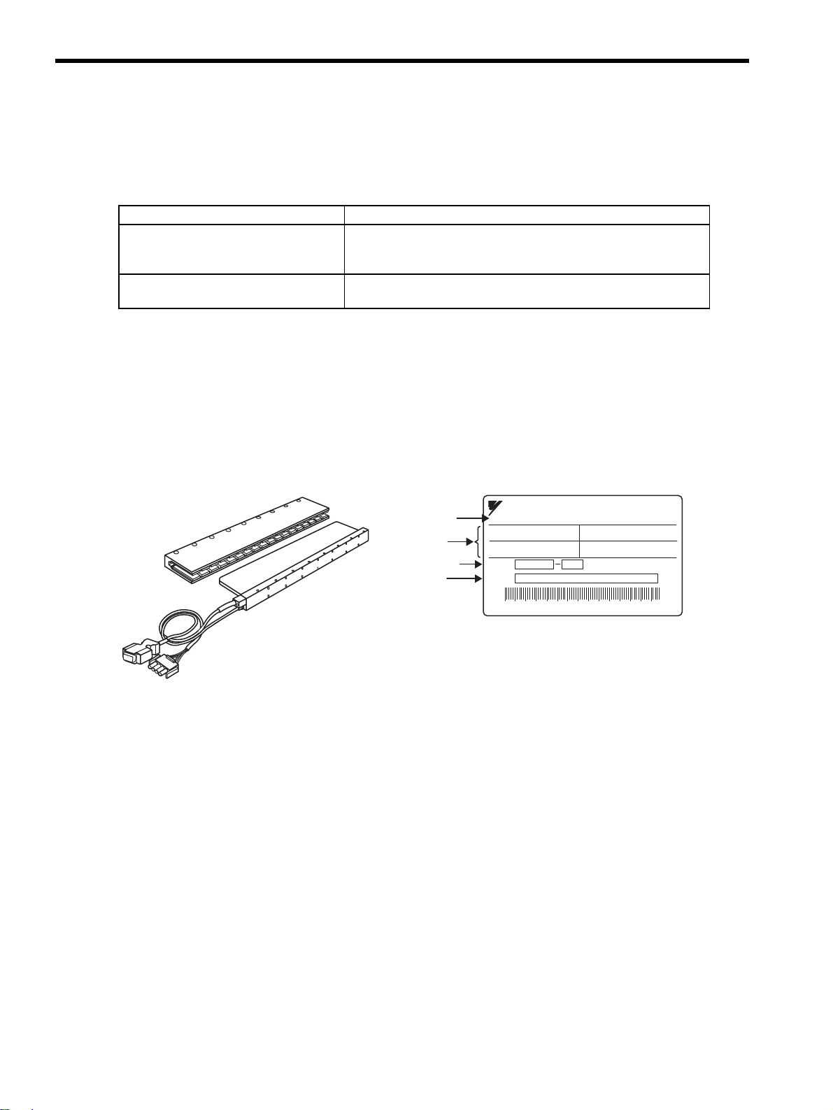
1.1.2 Linear Servomotors
The location of the nameplate varies depending on the model of the linear servomotor. The nameplate is affixed
on both the coil assembly and the magnetic way.
(1) Coreless SGLGW and SGLGM Linear Servomotors
Check Items Comments
Are the delivered products the ones
that were ordered?
Check the model numbers marked on the nameplates on the linear
servomotor and SERVOPACK. (Refer to the descriptions of model
numbers in the following section.)
Is there any damage? Check the overall appearance, and check for damage or scratches that
may have occurred during shipping.
CORELESSLINEARSERVOMOTOR
SGLGW-40A140B
94 0.8
47
WA
N
B
Ins.
O/N
S/N
YASKAWAELECTRICCORPORATIONJAPAN
Servomotor
model
Ratings
SerialNo.
Nameplate
OrderNo.
CoilassemblyandMagneticway
1.1 Checking Products
1-3
1
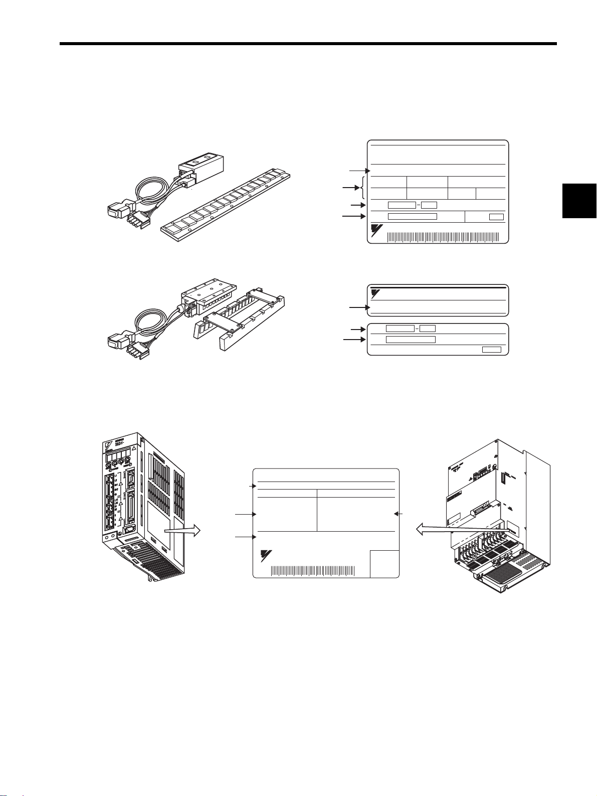
(2) SGLFW and SGLFM Linear Servomotors with F-type Iron Core and
SGLTW and SGLTM Linear Servomotors with T-type Iron Core
Note: The location of the nameplate varies depending on the model and capacity of the linear servomotor.
1.1.3 SERVOPACKs
LinearSERVOMOTOR
TYPE
200 W
1.3 A
80 N
200 V
2.5 m/s
ins.B
O/N
S/N
YASKAWAELECTRICMADEINJAPAN
DATE
SGLFW-35A120A
Servomotor
model
Ratings
SerialNo.
Nameplate
Nameplate
OrderNo.
Servomotor
model
SerialNo.
OrderNo.
Coilassembly
Magneticway
SGLFWandSGLFM
SGLTWandSGLTM
YASKAWA
TYPE:
O/N
S/N
MADEINJAPAN DATE
SGLFM-20756A
Serial
number
S/N
YASKAWAELECTRIC
MADEINJAPAN
412808-15-1
SERVOPACK
MODEL
AC-INPUT AC-OUTPUT
VOLTS
Hz
PHASE
AMPS
200-230
50/60
3
18.6
VOLTS
PHASE
AMPS
KU(MP)
0-230
3
24.8
3.0(4.0)
SGDH-30AE
SGDHfor50Wto5.0kW SGDHfor7.5kW
SERVOPACK
model
Applicable
powersupply
Applicable
motor
capacity

1 Outline
1.1.4 Serial Converter Units
1-4
1.1.4 Serial Converter Units
Nameplate
SERIALCONVERTER
MODELJZDP-D006-156
YASKAWAELECTRICCORPORATION
JAPAN
For:-
O/N
S/N
--
SerialNo.
OrderNo.
Serial
converter
model
1.2 Product Part Names
1-5
1
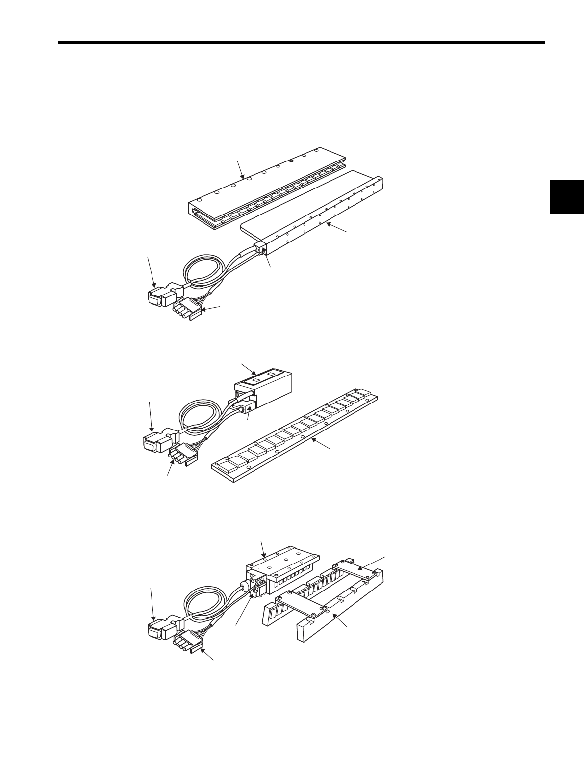
1.2 Product Part Names
1.2.1 Linear Servomotors
(1)
Coreless SGLGW and SGLGM
(2) SGLFW and SGLFM With F-type Iron Core
(3)
SGLTW and SGLTM With T-type Iron Core
Magneticway
Coilassembly
Hallsensorunit
Maincircuitcableforlinearservomotor
Hallsensorcable
Magneticway
Coilassembly
Hallsensor
unit
Maincircuitcablefor
linearservomotor
Hallsensorcable
Magneticway
Coilassembly
Hallsensorunit
Maincircuitcablefor
linearservomotor
Spacerfor
installation
Hallsensorcable
1 Outline
1.2.2 SERVOPACKs
1-6
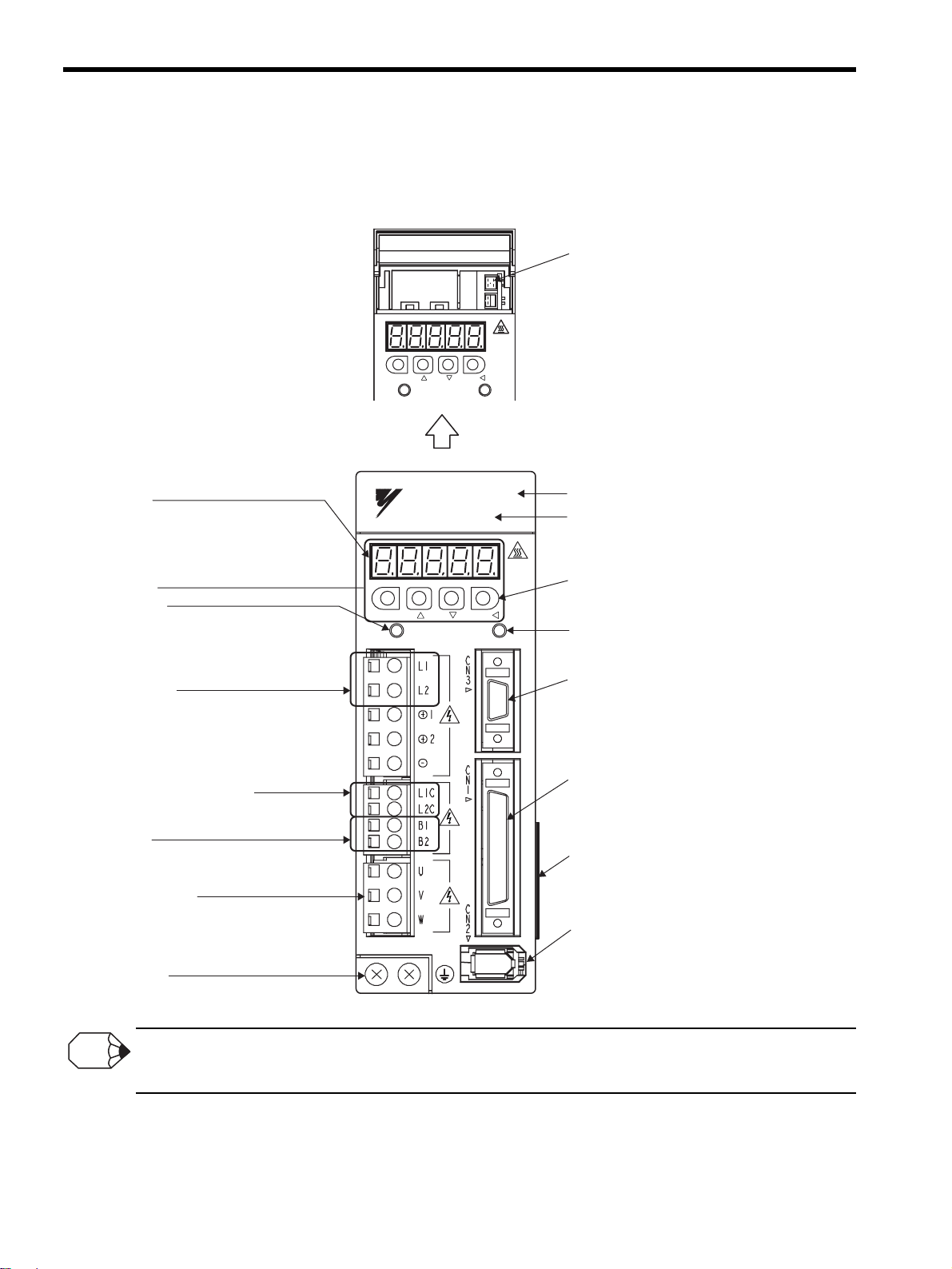
1.2.2 SERVOPACKs
(1) SGDH for 50 W to 5.0 kW
Connecting terminal of DC Reactor
For connecting a reactor, refer to 7.5.5 DC Reactor for Harmonic Suppression.
Referto2.3SERVOPACKModel
Designations.
Withthefrontcoveropen
SERVOPACKmodel
YASKAWA
YASKAWA
SERVOPACK
SGDH-
MODE/SET
CHARGE POWER
DATA/
MODE/SET DATA/
CHARGE POWER
Paneldisplay
5-digit,7-segmentLEDusedtodisplay
SERVOPACKstatus,alarmstatus,andother
valueswhenparametersareinput.
Referto8.1.2KeyNamesandFunctions.
Paneloperator
Chargeindicator
Lightswhenthemaincircuitpowersupplyis
ONandstayslitaslongasthemaincircuitpower
supplycapacitorremainscharged.Therefore,
donottouchtheSERVOPACKevenafterthepower
supplyisturnedOFFiftheindicatorislit.
Maincircuitpower
supplyterminals
Usedformaincircuitpowersupplyinput.
Referto7.2WiringMainCircuit.
Usedforcontrolpowersupplyinput.
Referto7.2WiringMainCircuit.
Controlpowersupplyterminals
Usedtoconnectexternalregenerativeresistors.
Referto7.6ConnectingRegenerativeResistors.
Regenerative
resistorconnectingterminals
Referto7.2WiringMainCircuit.
Groundterminal
Besuretoconnecttoprotectagainstelectricalshock.
Servomotorterminals
Connectstotheservomotorpowerline.
Referto7.2WiringMainCircuit.
CN5Analogmonitorconnector
Usedtomonitormotorspeed,force
reference,andothervaluesthrough
aspecialcable.
Referto6.8.3CablesforAnalogMonitoror
10.5AnalogMonitor.
Frontcover
PowerONindicator
LightswhenthecontrolpowersupplyisON.
Panelkeys
Usedtosetparameters.
Referto8.1.2KeyNamesandFunctions.
Referto6.8.1CablesforConnectingPersonal
Computerand6.8.2DigitalOperator.
CN3Connectorforpersonalcomputermonitoring
anddigitaloperator
Usedtocommunicatewithapersonalcomputer
ortoconnectadigitaloperator.
CN1I/Osignalconnector
Usedforreferenceinputsignalsand
sequenceI/Osignals.
Referto7.4ExamplesofI/OSignalConnections.
Nameplate(sideview)
IndicatestheSERVOPACKmodelandratings.
Referto1.1.3SERVOPACKs.
CN2Encoderconnector
Connectstotheserialconverterunit.
Referto7.3WiringEncoders.
INFO

1.2 Product Part Names
1-7
1
(2) SGDH for 7.5 kW
* Control circuit terminal and regenerative resistor connecting terminals differ the position of the termi-
nal block by the SERVOPACK model.
Refer to Chapter 4 SERVOPACK Specifications and Dimensional Drawings for details.
SERVOPACK model SGDH-75AE: Refer to 4.7.7 Three-phase 200 V: 7.5 kW (75AE) and
4.9.1 Three-phase 200 V: 7.5 kW (75AE-P).
SERVOPACK model SGDH-75DE: Refer to 4.7.8 Three-phase 400 V: 7.5 kW (75DE) and
4.9.2 Three-phase 400 V: 7.5 kW (75DE-P).
L1 L2 L3
U
B2B1
+
VW
!
WARNING
MODE/SET
Ve r.
POWER
CHARGE
SGDH-
SERVOPACK 200V
YASKAWA
Powerindicator
Paneloperator
Chargeindicator
L1C
CN1 CN2
L2C
Maincircuitpowersupply
terminals:L1,L2,L3
Servomotorterminals:U,V,W
Regenerativeresistor
connectingterminals:B1,B2
CN3Connectorfor
personalcomputer
monitoringand
digitaloperator
Nameplate(sideview)
CN2Encoderconnector
CN1I/Osignalconnector
Controlcircuit
terminal
SERVOPACKmodel
Groundterminal
DATA/
BATTERY
Paneldisplay
CN5Analog
monitorconnector
Panelswitch
CN8
CN5
CN3
∗
∗
1 Outline
1.3.1 Single-phase, 200 V Main Circuit
1-8
1.3 Examples of Servo System Configurations
This section describes examples of basic servo system configuration.
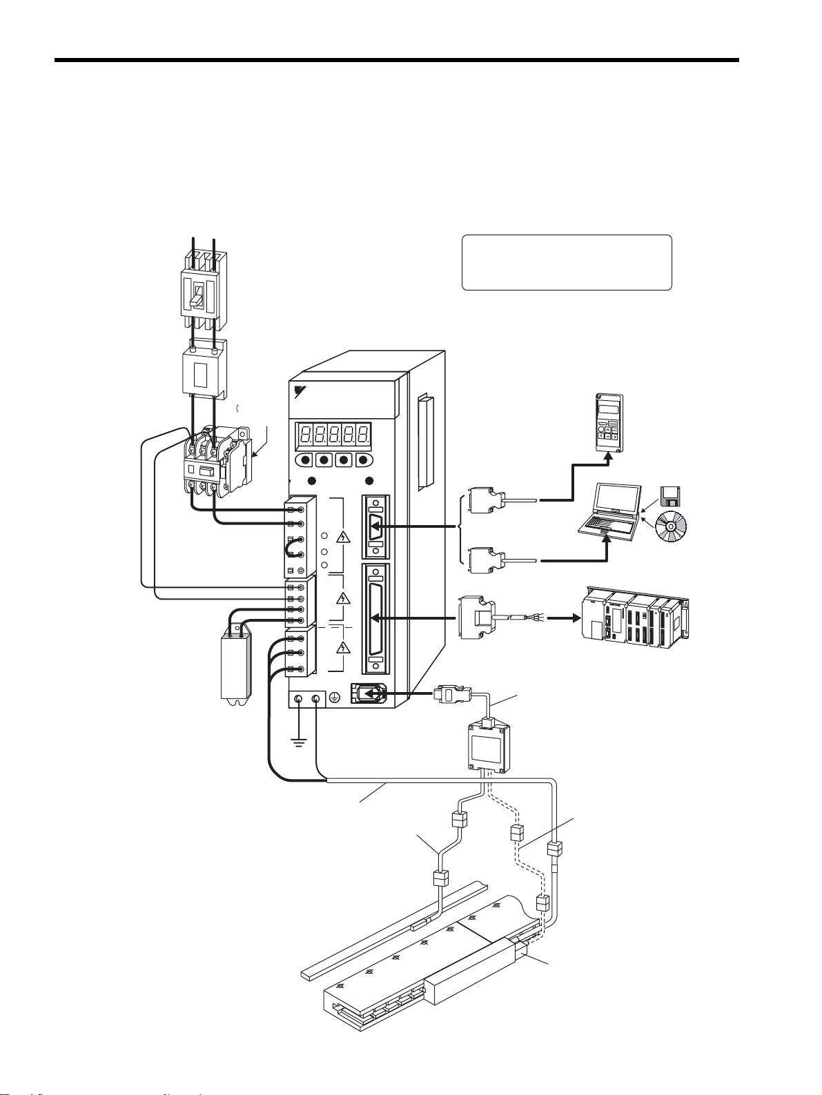
1.3.1 Single-phase, 200 V Main Circuit
Regenerative
resistor
Noisefilter
Molded-case
circuitbreaker
(MCCB)
Magnetic
contactor
Digital
operator
Personalcomputer
Hostcontroller
Connectioncable
fordigitaloperator
Connectioncable
forpersonalcomputer
(Referto2.6.1.)
(Referto2.6.1.)
(Referto2.6.1.)
(Referto2.6.4.)
(Referto2.6.5.)
Referto
2.6.3)
(Referto2.6.3)
(Referto2.6.2)
I/Osignalcable
Note:To connectaDCreactor,referto
7.5.5DCReactorforHarmonic
Suppression.
SGDH-AE
SERVOPACK
Powersupply
Single-phase200VAC
Protectsthepowersupply
linebyshuttingthecircuit
OFFwhenanovercurrent
isdetected.
Eliminatesexternal
noisefromthepower
line.
Connectanexternal
regenerativeresistor
toterminalsB1andB2
iftheregenerative
capacityisinsufficient.
TurnstheservoON
andOFF.
Installasurge
suppressor.
Linearscale
(Tobeprovidedby
users.)
Hallsensorunit
Connectioncable
forhallsensor
Encoder
cable
Maincircuitcablefor
linearservomotor
Serialconverterunit
Connectioncable
forserialconverterunit
(Referto2.5.)
(Referto2.5.)
(Referto2.5.)
(Referto2.5.)
(Referto2.4.)
RT
C
N
3
C
N
1
L1C
L2C
B1
B2
U
V
W
L1
L2
+1
MODE/SET
DATA/
CHARGE POWER
C
N
SGDH-
SERVOPACK
200V
YASKAWA
+2
-
CorelessLinearServomotor

1.3 Examples of Servo System Configurations
1-9
1
1.3.2 Three-phase, 200 V Main Circuit
Regenerative
resistor
Noisefilter
Molded-case
circuitbreaker
(MCCB)
Magnetic
contactor
I/Osignalcable
Powersupply
Three-phase200VAC
RST
Protectsthepower
supplylinebyshutting
thecircuitOFFwhen
anovercurrentis
detected.
Eliminatesexternalnoise
fromthepowerline.
Connectanexternal
regenerativeresistor
toterminalsB1andB2
iftheregenerative
capacityisinsufficient.
Turnstheservo
ONandOFF.
Installasurge
suppressor.
(Referto2.6.1.)
(Referto2.6.4.)
(Referto2.6.5.)
(Referto
2.6.3.)
(Referto2.6.3.)
(Referto2.6.2.)
Connectioncablefor
digitaloperator
Connectioncablefor
personalcomputer
(Referto2.6.1.)
Linearservomotorwithcore
Linearscale
(Tobeprovidedby
users)
Encoder
cable
Maincircuitcablefor
linearservomotor
Serialconverterunit
Connectioncablefor
serialconverterunit
(Referto2.5.)
(Referto2.5.)
(Referto2.5.)
(Referto2.5.)
(Referto2.4.)
Personalcomputer
Hostcontroller
L1
L2
L3
U
V
W
L1C
L2C
B1
B2
B3
1
2
C
N
3
C
N
1
C
N
2
MODE/SET
DATA/
CHARGE POWER
YASKAWA
SERVOPACK
SGD
H-
200V
*1
*3
*2
*3:To connectaDCreactor,referto7.5.5DCReactorforHarmonic
Suppression.
*1:Thepositiveterminalforthemaincircuitisonlyavailableforuse
inthethree-phase(200VAC,7.5kW)SERVOPACKs.
Donotusethepositiveterminals1or2.
*2:Beforeconnectinganexternalregenerativeresistorto
theSERVOPACK,besuretodisconnecttheleadbetweenterminals
B2andB3.
Digital
operator
(Referto2.6.1.)
SGDH-AE
SERVOPACK
Connectioncable
forhallsensor
 Loading...