


 Loading...
Cat. No. V084-E1-01
NT11
Programmable Terminal
USER’S MANUAL
NT11
Programmable Terminal
User’s Manual
Produced January 2004
iv
Notice:
OMRON products are manufactured for use according to proper procedures by a qualified operator and only for the purposes described in this manual.
The following conventions are used to indicate and classify precautions in this manual. Always heed the information provided with them. Failure to heed precautions can result in injury to people or damage to property.
!DANGER Indicates an imminently hazardous situation which, if not avoided, will result in death or serious injury.
!WARNING Indicates a potentially hazardous situation which, if not avoided, could result in death or serious injury.
!Caution Indicates a potentially hazardous situation which, if not avoided, may result in minor or moderate injury, or property damage.
OMRON Product References
All OMRON products are capitalized in this manual. The word “Unit” is also capitalized when it refers to an OMRON product, regardless of whether or not it appears in the proper name of the product.
The abbreviation “Ch,” which appears in some displays and on some OMRON products, often means “word” and is abbreviated “Wd” in documentation in this sense.
The abbreviation “PLC” means Programmable Controller. “PC” is used, however, in some Programming Device displays to mean Programmable Controller.
“Host” means a personal computer that controls the NT11.
Visual Aids
The following headings appear in the left column of the manual to help you locate different types of information.
Note Indicates information of particular interest for efficient and convenient operation of the product.
1,2,3... 1. Indicates lists of one sort or another, such as procedures, checklists, etc.
OMRON, 2004
All rights reserved. No part of this publication may be reproduced, stored in a retrieval system, or transmitted, in any form, or by any means, mechanical, electronic, photocopying, recording, or otherwise, without the prior written permission of OMRON.
No patent liability is assumed with respect to the use of the information contained herein. Moreover, because OMRON is constantly striving to improve its high-quality products, the information contained in this manual is subject to change without notice. Every precaution has been taken in the preparation of this manual. Nevertheless, OMRON assumes no responsibility for errors or omissions. Neither is any liability assumed for damages resulting from the use of the information contained in this publication.
v
vi
|
TABLE OF CONTENTS |
|
PRECAUTIONS . . . . . . . . . . . . . . . . . . . . . . . . . . . . . . . . . . . |
xi |
|
1 |
Intended Audience . . . . . . . . . . . . . . . . . . . . . . . . . . . . . . . . . . . . . . . . . . . . . . . . . . . . . . . . . |
xii |
2 |
General Precautions . . . . . . . . . . . . . . . . . . . . . . . . . . . . . . . . . . . . . . . . . . . . . . . . . . . . . . . . |
xii |
3 |
Safety Precautions . . . . . . . . . . . . . . . . . . . . . . . . . . . . . . . . . . . . . . . . . . . . . . . . . . . . . . . . . |
xii |
SECTION 1 |
|
|
Functions of the NT11 . . . . . . . . . . . . . . . . . . . . . . . . . . . . . . |
1 |
|
1-1 |
Getting Starting . . . . . . . . . . . . . . . . . . . . . . . . . . . . . . . . . . . . . . . . . . . . . . . . . . . . . . . . . . . |
2 |
1-2 |
Role and Operation of NT11 . . . . . . . . . . . . . . . . . . . . . . . . . . . . . . . . . . . . . . . . . . . . . . . . . |
2 |
1-3 |
Functions of NT11 . . . . . . . . . . . . . . . . . . . . . . . . . . . . . . . . . . . . . . . . . . . . . . . . . . . . . . . . . |
4 |
1-4 |
System Configuration . . . . . . . . . . . . . . . . . . . . . . . . . . . . . . . . . . . . . . . . . . . . . . . . . . . . . . |
8 |
1-5 |
Direct Connection Function. . . . . . . . . . . . . . . . . . . . . . . . . . . . . . . . . . . . . . . . . . . . . . . . . . |
9 |
1-6 |
Before Operating . . . . . . . . . . . . . . . . . . . . . . . . . . . . . . . . . . . . . . . . . . . . . . . . . . . . . . . . . . |
12 |
SECTION 2 |
|
|
Hardware Settings and Connections. . . . . . . . . . . . . . . . . . . |
15 |
|
2-1 |
Description of Parts and Settings. . . . . . . . . . . . . . . . . . . . . . . . . . . . . . . . . . . . . . . . . . . . . . |
16 |
2-2 |
Installation . . . . . . . . . . . . . . . . . . . . . . . . . . . . . . . . . . . . . . . . . . . . . . . . . . . . . . . . . . . . . . . |
19 |
2-3 |
Connecting to the NT Support Tool. . . . . . . . . . . . . . . . . . . . . . . . . . . . . . . . . . . . . . . . . . . . |
22 |
2-4 |
Connection to a PLC by the Host Link (RS-232C Type) . . . . . . . . . . . . . . . . . . . . . . . . . . . |
22 |
2-5 |
Connection to a PLC by the Host Link (RS-422A Type) . . . . . . . . . . . . . . . . . . . . . . . . . . . |
38 |
2-6 |
Connection to a PLC by the NT Link (RS-232C Type) . . . . . . . . . . . . . . . . . . . . . . . . . . . . |
50 |
2-7 |
Connection to a PLC by the NT Link (RS-422A Type) . . . . . . . . . . . . . . . . . . . . . . . . . . . . |
55 |
2-8 |
Connecting a Printer . . . . . . . . . . . . . . . . . . . . . . . . . . . . . . . . . . . . . . . . . . . . . . . . . . . . . . . |
57 |
SECTION 3 |
|
|
System Menu Operation. . . . . . . . . . . . . . . . . . . . . . . . . . . . . |
59 |
|
3-1 |
Operation Flow by the System Menu . . . . . . . . . . . . . . . . . . . . . . . . . . . . . . . . . . . . . . . . . . |
60 |
3-2 |
Starting the NT11. . . . . . . . . . . . . . . . . . . . . . . . . . . . . . . . . . . . . . . . . . . . . . . . . . . . . . . . . . |
60 |
3-3 |
Operation Modes and the System Menu . . . . . . . . . . . . . . . . . . . . . . . . . . . . . . . . . . . . . . . . |
61 |
3-4 |
Initializing Memory. . . . . . . . . . . . . . . . . . . . . . . . . . . . . . . . . . . . . . . . . . . . . . . . . . . . . . . . |
64 |
3-5 |
Transferring the System Program . . . . . . . . . . . . . . . . . . . . . . . . . . . . . . . . . . . . . . . . . . . . . |
66 |
3-6 |
Registering the Screen Data. . . . . . . . . . . . . . . . . . . . . . . . . . . . . . . . . . . . . . . . . . . . . . . . . . |
69 |
3-7 |
Setting the Conditions of Communications with the PLC by Using the Memory Switches. |
71 |
3-8 |
Starting the Operation . . . . . . . . . . . . . . . . . . . . . . . . . . . . . . . . . . . . . . . . . . . . . . . . . . . . . . |
77 |
3-9 |
Backlight OFF . . . . . . . . . . . . . . . . . . . . . . . . . . . . . . . . . . . . . . . . . . . . . . . . . . . . . . . . . . . . |
78 |
3-10 |
System Maintenance . . . . . . . . . . . . . . . . . . . . . . . . . . . . . . . . . . . . . . . . . . . . . . . . . . . . . . . |
80 |
vii
TABLE OF CONTENTS
SECTION 4 |
|
|
NT11 Functions . . . . . . . . . . . . . . . . . . . . . . . . . . . . . . . . . . . . |
85 |
|
4-1 |
Outline of Functions . . . . . . . . . . . . . . . . . . . . . . . . . . . . . . . . . . . . . . . . . . . . . . . . . . . . . . . |
86 |
4-2 |
Screen Display. . . . . . . . . . . . . . . . . . . . . . . . . . . . . . . . . . . . . . . . . . . . . . . . . . . . . . . . . . . . |
87 |
4-3 |
Areas for Control/Notification. . . . . . . . . . . . . . . . . . . . . . . . . . . . . . . . . . . . . . . . . . . . . . . . |
89 |
4-4 |
Memory Tables . . . . . . . . . . . . . . . . . . . . . . . . . . . . . . . . . . . . . . . . . . . . . . . . . . . . . . . . . . . |
94 |
4-5 |
Bar Graphs . . . . . . . . . . . . . . . . . . . . . . . . . . . . . . . . . . . . . . . . . . . . . . . . . . . . . . . . . . . . . . . |
96 |
4-6 |
Numeral Setting. . . . . . . . . . . . . . . . . . . . . . . . . . . . . . . . . . . . . . . . . . . . . . . . . . . . . . . . . . . |
97 |
4-7 |
Menu Screen Function. . . . . . . . . . . . . . . . . . . . . . . . . . . . . . . . . . . . . . . . . . . . . . . . . . . . . . |
99 |
4-8 |
Password Screen Display Function . . . . . . . . . . . . . . . . . . . . . . . . . . . . . . . . . . . . . . . . . . . . |
100 |
4-9 |
Display History Screen Function. . . . . . . . . . . . . . . . . . . . . . . . . . . . . . . . . . . . . . . . . . . . . . |
101 |
4-10 |
Daily Report/Display History Printing Function. . . . . . . . . . . . . . . . . . . . . . . . . . . . . . . . . . |
102 |
SECTION 5 |
|
|
Using Host Link/NT Link. . . . . . . . . . . . . . . . . . . . . . . . . . . . |
107 |
|
5-1 |
Screen Creation Procedure . . . . . . . . . . . . . . . . . . . . . . . . . . . . . . . . . . . . . . . . . . . . . . . . . . |
108 |
5-2 |
Outline of Host Link/NT Link Operation . . . . . . . . . . . . . . . . . . . . . . . . . . . . . . . . . . . . . . . |
109 |
5-3 |
Memory Table Entries and Bar Graph. . . . . . . . . . . . . . . . . . . . . . . . . . . . . . . . . . . . . . . . . . |
115 |
5-4 |
Numeral Setting. . . . . . . . . . . . . . . . . . . . . . . . . . . . . . . . . . . . . . . . . . . . . . . . . . . . . . . . . . . |
126 |
5-5 |
NT11 Status Control . . . . . . . . . . . . . . . . . . . . . . . . . . . . . . . . . . . . . . . . . . . . . . . . . . . . . . . |
129 |
5-6 |
Notification of the Operating Status to the PLC (Determining the NT11 Operating Status) |
132 |
SECTION 6 |
|
|
Troubleshooting and Maintenance . . . . . . . . . . . . . . . . . . . . |
135 |
|
6-1 |
Troubleshooting . . . . . . . . . . . . . . . . . . . . . . . . . . . . . . . . . . . . . . . . . . . . . . . . . . . . . . . . . . . |
136 |
6-2 |
Responding to Displayed Error Messages. . . . . . . . . . . . . . . . . . . . . . . . . . . . . . . . . . . . . . . |
138 |
6-3 |
Inspection and Cleaning . . . . . . . . . . . . . . . . . . . . . . . . . . . . . . . . . . . . . . . . . . . . . . . . . . . . |
142 |
Appendices |
|
|
A |
Specifications . . . . . . . . . . . . . . . . . . . . . . . . . . . . . . . . . . . . . . . . . . . . . . . . . . . . . . . . . . . . |
145 |
B |
Dimensions . . . . . . . . . . . . . . . . . . . . . . . . . . . . . . . . . . . . . . . . . . . . . . . . . . . . . . . . . . . . . . |
149 |
C |
Transporting and Storing the NT11 . . . . . . . . . . . . . . . . . . . . . . . . . . . . . . . . . . . . . . . . . . . |
151 |
D |
Making the Cable . . . . . . . . . . . . . . . . . . . . . . . . . . . . . . . . . . . . . . . . . . . . . . . . . . . . . . . . . |
153 |
E |
Making the Cable for Connecting a Personal Computer . . . . . . . . . . . . . . . . . . . . . . . . . . . |
155 |
F |
NT11 Internal Processing . . . . . . . . . . . . . . . . . . . . . . . . . . . . . . . . . . . . . . . . . . . . . . . . . . . |
157 |
G |
Model List . . . . . . . . . . . . . . . . . . . . . . . . . . . . . . . . . . . . . . . . . . . . . . . . . . . . . . . . . . . . . . . |
159 |
H |
Special Characters . . . . . . . . . . . . . . . . . . . . . . . . . . . . . . . . . . . . . . . . . . . . . . . . . . . . . . . . |
163 |
Index. . . . . . . . . . . . . . . . . . . . . . . . . . . . . . . . . . . . . . . . . . . . . |
165 |
|
Revision History . . . . . . . . . . . . . . . . . . . . . . . . . . . . . . . . . . . |
169 |
|
viii

About this Manual:
This manual describes the basic functions and operation procedures of the NT-series programmable terminal NT11, its operations when connected to a PLC, and includes the sections described below.
Please read this manual carefully and be sure you understand the information provided before attempting to install and operate the NT-series programmable terminal NT11.
Section 1 describes the operation functions, system configuration, and the direct connection function of the NT11.
Section 2 describes the hardware settings, installation to an operation panel, connection to optional devices and PLC.
Section 3 describes the operation of the System Menu and the maintenance of the NT11.
Section 4 describes the functions of the NT11 when it is connected to a PLC.
Section 5 describes how to use the NT11 when it is connected to the PLC using the host link or NT link.
Section 6 describes the procedures to follow when the NT11 does not operate correctly.
APPENDIX describes the specifications and the method for making connecting cables, and includes an area list for the PLC.
!WARNING Failure to read and understand the information provided in this manual may result in personal injury or death, damage to the product, or product failure. Please read each section in its entirety and be sure you understand the information provided in the section and related sections before attempting any of the procedures or operations given.
ix
Related Manuals and Their Contents:
The related manuals are listed below.
The @ symbol at the end of the manual number is the revision history symbol.
[Operating the programmable terminal and communicating with the host]
• NT11 Programmable Terminal User’s Manual (V084-E1-@)
- - - - - - - - - - - - - - - - - - - - - - - - - - - - - - - - - - - - - - - - - - - - - - - - - - - - - - - - - - - - - This manual
This user’s manual is the manual for the NT11-V@ itself.
The NT11 is a unit which integrates a programmable terminal body. This user’s manual describes the functions and handling of the programmable terminal body.
[Creating and transferring screen data]
•NT-series Support Tool Operation Manual (V061-E1-@)
The screens displayed on the NT11 are created with the support tool and transferred to the NT11. This manual describes how to create and transfer screen data.
x
PRECAUTIONS
This section provides general precautions for using the Programmable Terminal.
The information contained in this section is important for the safe and reliable application of the Programmable Terminal. You must read this section and understand the information contained before attempting to set up or operate a Programmable Terminal.
1 |
Intended Audience . . . . . . . . . . . . . . . . . . . . . . . . . . . . . . . . . . . . . . . . . . . . . |
xii |
2 |
General Precautions . . . . . . . . . . . . . . . . . . . . . . . . . . . . . . . . . . . . . . . . . . . . |
xii |
3 |
Safety Precautions. . . . . . . . . . . . . . . . . . . . . . . . . . . . . . . . . . . . . . . . . . . . . . |
xii |
xi
Intended Audience |
1 |
1 Intended Audience
This manual is intended for the following personnel, who must also have knowledge of electrical systems (an electrical engineer or the equivalent).
•Personnel in charge of introducing FA systems into production facilities.
•Personnel in charge of designing FA systems.
•Personnel in charge of installing and connecting FA systems.
•Personnel in charge of managing FA systems and facilities.
2 General Precautions
The user must operate the product according to the performance specifications described in the user’s manuals.
Before using the product under conditions that are not described in the manual or applying the product to nuclear control systems, railroad systems, aviation systems, vehicles, combustion systems, medical equipment, amusement machines, safety equipment, and other systems, machines and equipment that may have a serious influence on lives and property if used improperly, consult your OMRON representative.
Make sure that the ratings and performance characteristics of the product are sufficient for the systems, machines, and equipment, and be sure to provide the systems, machines, and equipment with double safety mechanisms.
This manual provides information for using the Programmable Terminal. Be sure to read this manual before attempting to use the software and keep this manual close at hand for reference during operation.
!WARNING It is extremely important that Programmable Terminals and related devices be used for the specified purpose and under the specified conditions, especially in applications that can directly or indirectly affect human life. You must consult with your OMRON representative before applying Programmable Terminals to the above-mentioned applications.
!WARNING Do not use input functions such as PT touch switches for applications where danger to human life or serious damage is possible, or for emergency switch applications.
3 Safety Precautions
Safety Conventions and their Meanings
Read these safety precautions carefully and make sure you understand them before using the Programmable Terminal so that you can use it safely and correctly.
This user’s manual uses the following conventions and symbols to indicate cautions, warnings, and dangers in order to ensure safe use of the NT11. The cautions, warnings, and dangers shown here contain important information related to safety. The instructions in these cautions, warnings, and dangers must be observed.
The conventions used and their meanings are presented below.
!WARNING Indicates information that, if not heeded, could possibly result in loss of life or serious injury.
xii

Safety Precautions |
3 |
Caution Indicates information that, if not heeded, could result in relatively serious or minor injury, damage to the product, or faulty operation.
 WARNING
Do not attempt to take the Unit apart and do not touch any internal parts while the power is being supplied. Doing either of these may result in electrical shock.
xiii

Safety Precautions |
3 |
xiv
SECTION 1
Functions of the NT11
NT11 is a new programmable terminal (PT) which incorporates a host interface unit in a programmable terminal body. It can be easily installed and used.
This section gives the operation examples and characteristics of the NT11 so that you will understand the applications of the NT11.
1-1 |
Getting Starting . . . . . . . . . . . . . . . . . . . . . . . . . . . . . . . . . . . . . . . . . . . . . . . . |
2 |
|
1-2 Role and Operation of NT11. . . . . . . . . . . . . . . . . . . . . . . . . . . . . . . . . . . . . . |
2 |
||
|
1-2-1 |
Operations of NT11 . . . . . . . . . . . . . . . . . . . . . . . . . . . . . . . . . . . . . |
3 |
1-3 |
Functions of NT11 . . . . . . . . . . . . . . . . . . . . . . . . . . . . . . . . . . . . . . . . . . . . . |
4 |
|
|
1-3-1 |
Features. . . . . . . . . . . . . . . . . . . . . . . . . . . . . . . . . . . . . . . . . . . . . . . |
4 |
|
1-3-2 Principal Functions of NT11. . . . . . . . . . . . . . . . . . . . . . . . . . . . . . . |
5 |
|
|
1-3-3 |
Displays . . . . . . . . . . . . . . . . . . . . . . . . . . . . . . . . . . . . . . . . . . . . . . |
6 |
|
1-3-4 |
System Keys . . . . . . . . . . . . . . . . . . . . . . . . . . . . . . . . . . . . . . . . . . . |
7 |
1-4 |
System Configuration . . . . . . . . . . . . . . . . . . . . . . . . . . . . . . . . . . . . . . . . . . . |
8 |
|
|
1-4-1 Peripheral Devices That Can Be Connected. . . . . . . . . . . . . . . . . . . |
8 |
|
1-5 |
Direct Connection Function . . . . . . . . . . . . . . . . . . . . . . . . . . . . . . . . . . . . . . |
9 |
|
|
1-5-1 |
NT Link . . . . . . . . . . . . . . . . . . . . . . . . . . . . . . . . . . . . . . . . . . . . . . |
9 |
|
1-5-2 Functions of the Allocated Bits and Words . . . . . . . . . . . . . . . . . . . |
10 |
|
1-6 |
Before Operating. . . . . . . . . . . . . . . . . . . . . . . . . . . . . . . . . . . . . . . . . . . . . . . |
12 |
|
1

Getting Starting |
Section 1-1 |
1-1 Getting Starting
|
To ensure that the NT11 works correctly, carefully observe the following when |
|
installing and handling it. |
Location |
Do not install the NT11 in a location subject to the following conditions; |
|
• Near a computer, radio transmitter or receiver, etc. |
|
• Dust, chemicals, or steam |
|
• Severe temperature fluctuations |
|
• High humidity and condensation |
|
• Strong electrical or magnetic fields |
|
• Poor ventilation |
|
• Severe vibration |
Handling |
Do not; |
|
• Subject the NT11 to strong shocks or vibrations |
|
• Put heavy objects on the NT11 |
|
• Supply a voltage different from the specified voltage |
|
• Disassemble or modify the NT11 |
Cautions on Cleaning |
To clean the front panel, use a soft, dry cloth. If it is very dirty, use diluted (2%) |
|
neutral detergent. |
|
Do not use volatile solvents such as benzene, thinner, or a chemically treated |
|
cloth. Their use will cause deformation or discoloration. |
Cautions on Afterimage |
If the same screen contents are kept displayed for a long time, an afterimage |
|
may occur. To prevent this problem, either set the afterimage prevention func- |
|
tion or make a program which periodically changes the displayed screen. |
Cautions on Operating the System Keys
Do not operate the system keys with sharply pointed objects, such as your fingernails or a screwdriver.
This could break the film.
1-2 Role and Operation of NT11
NT11 is a programmable terminal used to display and transmit the information in an FA site. The following gives a general description of the role and operation of the NT11 for those who use a programmable terminal (PT) for the first time.
Production Line Status Monitoring
The NT11 displays real-time information about the system and equipment operating status, etc.
Line 1 Status Machine:NT11-SF121 Product: 137 units
75%
2

|
Role and Operation of NT11 |
|
|
|
|
|
|
|
Section 1-2 |
Messages |
The NT11 warns of system or equipment failures and prompts the appropriate |
||||||||
|
|
remedial action. |
|
|
|
|
|
|
|
|
|
|
|
|
|
|
|
|
|
|
|
|
|
|
|
|
|
|
|
|
|
|
A l a |
r m |
|||||
|
|
Assembly line B |
|
|
|
||||
|
|
Positioning pin |
|
|
|
||||
Panel Switch Functions |
The NT11 can be used in place of external data input equipment such as an |
||||||||
|
|
operation panel, to transmit data to a PLC. |
|||||||
|
|
|
|
|
|
|
|||
|
|
Positioning |
|
|
|
||||
|
|
X-AXIS |
100 point |
|
|
|
|||
|
|
Y-AXIS |
150 point |
|
|
|
|||
|
|
Z-AXIS |
80 point |
|
|
|
|||
1-2-1 Operations of NT11 |
|
|
|
|
|
|
|||
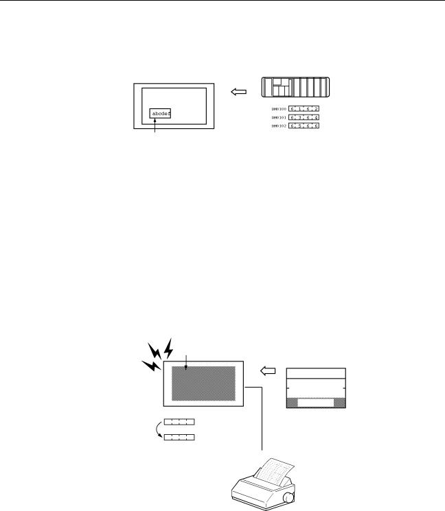
Displays Screens |
The information to be displayed (screen data) can be created on a computer |
||||||||
|
|
by using support tools and stored in the NT11. The screen data can be dis- |
|||||||
|
|
played on the NT11 in response to the instructions from a PLC or system keys |
|||||||
|
|
operation. |
|
|
|
|
|
|
|
|
|
|
|
|
|
|
|
|
|
|
|
|
|
|
|
PLC |
|||
|
|
|
|
|
The screen data designated by |
||||
|
|
|
|
|
instructions from PLC or System |
||||
|
|
|
|
|
keys operation is displayed. |
||||
Receives Data from a PLC |
NT11 can be connected to a PLC by a host link or NT link and receive neces- |
||||||||
|
|
sary data from the PLC. |
|||||||
|
|
|
|
Host link, NT link |
|||||
|
|
|
|
|
|
|
|
|
|
|
|
|
|
|
|
PLC |
|||
|
|
|
|
|
OMRON's PLC |
||||
Sends Data to a PLC |
Data input through a numeric key can be sent to a PLC. |
||||||||
|
|
Numeric keys |
|
|
|
|
|
|
|
|
|
|
|
|
|
PLC |
|||
|
|
|
|
|
|
ON/OFF information, |
|||
|
|
|
|
|
|
numeric data, etc. |
|||
3

Functions of NT11 |
Section 1-3 |
Screen Data |
The screen data to be displayed on the NT11 can be created by a computer |
|
by using support tools. Connect the NT11 to an IBM PC/AT or compatible with |
|
an RS-232C cable so that the screen data are transferred to the NT11. |
|
Create screen data. |
|
RS-232C |
|
|
|
PC/AT |
|
|
|
(support tools) |
Screen data
This connection is made only to transmit the screen data by using NT11 and tools.
1-3 Functions of NT11
|
The NT11 has the following features and functions; |
1-3-1 Features |
|
Downsized Body |
• The NT11 has the thinnest depth (31 mm or less in the panel) in the NT |
|
series. |
|
• It is very compact, with a width of 218 mm and a height of 113 mm. |
|
• Features three ports: for RS-232C, RS-422A, and printer output. |
|
• The tool connectors and the PLC communication connectors are used in |
|
common. |
Construction Best Suited to the FA Environment
•Easy-to-read screen even in direct sunlight.
•Waterproofed to a standard equivalent to IP65 and NEMA4.
160 dots
64 dots
Wide angle of visibility ±20°
A Host I/F Unit, Screen Data Memory, and a system program transfer ROM are All Incorporated
•There is no complicated installation work except a simple connection to a PLC.
•A flash memory is used for the screen data memory. There is no need of backup battery.
•A host link (direct), and an NT link are standard equipment.
4

Functions of NT11 |
Section 1-3 |
1-3-2 Principal Functions of NT11
Functions Related to the Data Display
•Character display
Characters of standard and double-width can be displayed. Characters can flash or be highlighted.
•Memory data display
Contents of the character-string memory table and the numeral memory table can be displayed. The memory table contents can be changed from the PLC.
•Bar graph display
Bar graphs corresponding to the contents of the numeral table can be displayed.
Functions Related to the Data Input
• Input by the system key
Data can be input, and the displayed screen changed, by using the numeric keys, function keys, and arrow keys on the panel of the NT11.
•Numeric setting function
The numeric values can be input at the operation site by the system key and sent to the PLC.
Other Functions
•Communications with a PLC
The host link, NT link is used to connect to a PLC for data communication.
•System function
The system setting and maintenance can be executed by using the System Menu on the screen.
•Screen data creation
The screen data can be created by using support tools on the computer and stored in the unit.
5

Functions of NT11 |
Section 1-3 |
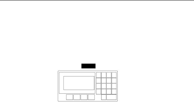
1-3-3 Displays
The NT11 can display elements such as characters, numeric value, and bar graphs on a screen. The screen data displayed on the NT11 are created by using support tools on a computer.
Characters |
Line 1 Status |
|
(character string) |
|
|
Characters (text) |
Machine:NT11-SF121 |
|
|
|
|
|
Product:137 units |
Numeric value |
|
(Numeral table) |
|
Bar graph |
75% |
|
|
|
Characters (text) |
Characters and marks which do not need to be changed can be written |
|
directly to the screen. |
Characters (character-string memory table)
Character-strings stored in the character-string memory table are displayed. The display characters can be changed by changing the data stored in the character-string memory table.
Numeric Values (numeral memory table)
|
Numbers stored in the numeral memory table are displayed. The display num- |
|
bers can be changed by changing the data stored in the numeral table. Hexa- |
|
decimal values can also be displayed. |
Bar Graphs |
The bar graph extends and contracts in proportion to the data stored in the |
|
numeral memory table. A percentage value can also be displayed simulta- |
|
neously. |
Marks |
Marks can be designed, created, and handled like characters by the user. |
Comparison with the NT11S
|
Model |
NT11 |
|
NT11S |
|
|
|
|
|
Basic performance |
Dimensions |
218 x 113 x 38.2 mm (W x H x D) |
||
|
|
|
|
|
|
Resolution |
160 x 64 dots (4.24 inches) |
|
|
|
|
|
|
|
|
Effective display area |
100 x 40 mm |
|
|
|
|
|
||
|
Display color |
Black & white (with yellow mode) |
||
|
|
|
|
|
|
Panel cut-out size (W x H) |
204.2 x 98.8 mm |
|
|
|
|
|
|
|
|
Max. number of registered screens |
250 |
|
|
|
|
|
|
|
|
Screen data capacity |
32 KB |
|
|
|
|
|
|
|
|
Function keys |
4 |
|
|
|
|
|
||
|
Other Keys |
Numeric Keys, Cursor Keys, Function Keys |
||
|
|
|
|
|
Special functions |
Emergency transfer mode* |
DIP switch pin 3 |
|
None |
|
|
|
|
|
|
Backlight service life |
50,000 hours min. |
|
10,000 hours min. |
|
|
|
|
|
Communications |
Host Link Speed |
Up to 115,200 |
|
9,600/19,200 |
|
|
|
|
|
|
Compatibility (Screen data types that can |
NT11-V1, NT11S |
|
NT11S |
|
be used.) |
|
|
|
*Emergency transfer mode: When power to the NT11 is turned ON with DIP switch pin 3 turned ON, data transfer mode will be entered directly without any other operation.
6
Functions of NT11 |
Section 1-3 |
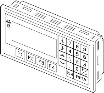
1-3-4 System Keys
The NT11 has system keys on its panel for input functions.
The system keys are used for inputting numerical values and for notifications to the PLC.
The system keys can be classified into the three types shown below.
-Numeric keys
-Arrow keys
-Function keys
NT11
Screen display
|
|
|
|
|
|
|
|
|
|
|
|
|
|
|
|
|
|
Function keys |
|
|
Numeric keys |
|||||
Arrow keys
•Numeric keys
These are the numeral keys from [0] to [9], the decimal point key [.], the sign key [+/–], the [CLR] key and the [ENTER] key. These keys are used for inputting numerical values.
•Arrow keys
Used to select the required numerical value input field when there is more than one on the screen.
•Function keys
Used for notifications from the NT11 to the PLC.
Also used to switch between the RUN mode and the system menu when the power is switched on.
!Caution Do not use input functions such as PT function keys for applications where danger to human life or serious property damage is possible, or as the emergency stop switch.
!Caution If function keys are pressed in rapid succession, their inputs may not be successfully received. Confirm that the input of a function key has been successfully received before moving on to the next operation.
!Caution Do not press function keys carelessly while the backlight is off or while nothing is displayed on the screen. Otherwise the system may operate unpredictably. Only press function keys after confirming system safety.
7
System Configuration |
Section 1-4 |
1-4 System Configuration
This section shows the configuration of a system that uses an NT11. For details on product models, refer to Appendix G Model List (page 159).
1-4-1 Peripheral Devices That Can Be Connected
The following peripheral devices can be connected to an NT11.
Host
Controls the NT11 as required while controlling machines and monitoring the production line.
Host Link: CS-series/CJ-series/C-series PLCs, CVM1/CV-series PLCs, SRM1 Can be connected to CPU Units, Host Link Units, and SRM1. However, connection is not possible to some models of CPU Unit and SRM1
(pages 23 and 39).
NT Link: C-series PLCs, CVM1/CV-series PLCs, SRM1
Can be connected to CPU Units and SRM1. However, connection is not possible to some models (pages 51 and 55).
RS-232C cable |
|
(15 m max.) |
|
An RS-422A/485 cable |
|
(500 m max.) can be |
|
connected through an |
|
RS-232C/RS-422A |
Personal computer |
Adapter. |
|
|
Running Windows 95, 98, |
|
NT, 2000, Me, XP |
NT11
Displays production line monitoring and commands to the operation site, and notifies the switch ON/OFF status and numeric value inputs to the host.
NT Support Tool
Used to create screens for the NT11 at the personal computer and transfer them to the NT11, and to make NT11 settings.
System installer
Used to change the system program of the NT11.
•NT Support Tool (page 22)
NT-series Support Tool Version 4.7 for Windows (Made by OMRON)
•NT-ZJCAT1-EV4.7 (CD-ROM version for IBM PC/AT or compatible computers)
•System installer (page 22)
System Installer (made by OMRON)
The System Installer is supplied as a standard accessory with the NT Support Tool (NT-ZJCAT1-EV4.7).
8
Direct Connection Function |
Section 1-5 |
1-5 Direct Connection Function
The communication method applied between the NT11 and the PLC is either a host link or NT link.
The NT11 can be used to refer to the contents necessary for the display information or to allocate the bits and words used for storing the input data to any area in the PLC. The NT11 can directly write and read such allocated bits and words so as to change the display elements, control the operating status, and notify the status.
This function is called the “direct connection function”. The NT11 is designed exclusively for use with the direct connection.
The bits and words allocated by the direct connection function are called “allocated bit” and “allocated word” respectively.
This function allows to read the information to be displayed on the NT11 from the memory area in the PLC and to write it to the memory table in the NT11. Also, the data input on the NT11 can be written to the PLC’s memory area. The NT11 screen status can be switched according to the PLC’s memory area, and the NT11’s status data can be written to the PLC’s memory area.
NT11 |
|
PLC |
|
Data memory area |
Internal relay area |
||||||
|
|
|
|
|
|
|
|
|
|
|
|
|
|
|
|
|
|
|
|
|
|
|
|
|
|
|
|
|
|
|
|
|
|
|
|
|
|
|
|
|
|
|
|
|
|
|
|
|
|
|
|
|
|
Auxiliary relay area |
Timer/counter |
Features of the Direct Connection Function
•The bits and words referring to operating status and work instruction information and those for storing input data can be freely allocated to almost any part of the PLC memory. Bits and words in the PLC can be referenced from any memory table.
•The NT11 can directly refer to PLC bit and word data so that it can be connected to a PLC without changing the PLC program which controls currently running production line.
•The area to control and notify the NT11 status, including display screens, ON/OFF of the backlight, and printing of daily reports and display histories, can be freely allocated to any part of the PLC memory.
The direct connection function allows the NT11 to directly read and write almost all bits and words in the PLC and to automatically change the NT11 screen display. This function can reduce the load on the PLC so that the program development efficiency of the PLC improves.
1-5-1 NT Link
|
The NT link is a new communication method applied between the NT11 and a |
|
PLC. |
|
The NT link uses the direct connection function and can execute high speed |
|
communications with a CPU (built-in NT link) of the CQM1, C200HS, and |
|
other PLCs. |
Features of the NT Link |
• High speed communications with specific types of PLCs can be executed. |
|
• Writing in units of bits to the PLC memory area is possible. (*) |
9
Direct Connection Function |
Section 1-5 |
•This can be used even when the PLC is in the RUN mode.
(*) Except a DM area.
The NT link is compatible with the host link. The NT11 screen data and the PLC programs handled by the host link direct connection can be used with for the NT link as they are.
1-5-2 Functions of the Allocated Bits and Words
Elements displayed on the NT11 and the NT11 status can be allocated to the bits and words of the PLC. By changing the contents of the bits and words, the NT11 can be controlled by the PLC. It is also possible to send data to the PLC by pressing the function keys on the panel of the NT11.
• Controlling the NT11 by a PLC
The following NT11 functions can be controlled by a PLC.
Screens: |
Display of designated screens, confirmation of screen |
|
numbers, etc. |
Memory tables: Writing to a memory table, copying from a memory table to another memory table, etc.
System control: ON/OFF of backlight, control of output of daily reports and display histories at a printer.
•Notifying from the NT11 to a PLC
Data in the NT11 is sent to a PLC when a numeric key is pressed. The following types of data are sent to a PLC.
-NT11 status
-Password input status
-Numeric values input by the numeral keys
-Function key input status
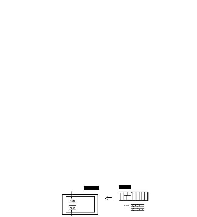
Functions of Display Elements
•Numeral memory table Allocation destination: Word
Numeral memory |
|
|
table entry 1 |
NT11 |
PLC |
(TIM003) |
CIO/IR 0005
Numeral memory table entry 150 (CIO/IR 0005)
Allocate numeral memory table entries to arbitrary words in the PLC. If word contents change when corresponding numeral memory table entry is displayed on the screen, the value on the screen will also change. Monitoring of words can also be made easily.
Reading and writing are executed so that the contents of allocated words are always the same as those of the numeral memory table entries.
10
Direct Connection Function |
Section 1-5 |
•Character-string memory table Allocation destination: Word
NT11 |
|
PLC |
("a", "b") ("c", "d") ("e", "f")
Character-string memory table entry 1
Number of allocated words: 3
First word: DM0100
Allocate character-string memory table entries to arbitrary words in the PLC. If word contents change when corresponding character-string memory table entry is displayed on the screen, the value on the screen will also change. Messages can be displayed easily.
Reading and writing are executed so that the contents of allocated words are always the same as those of the character-string memory table entries.
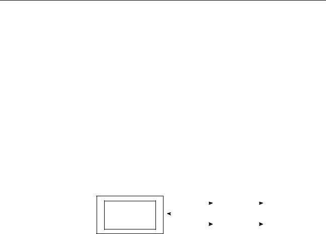
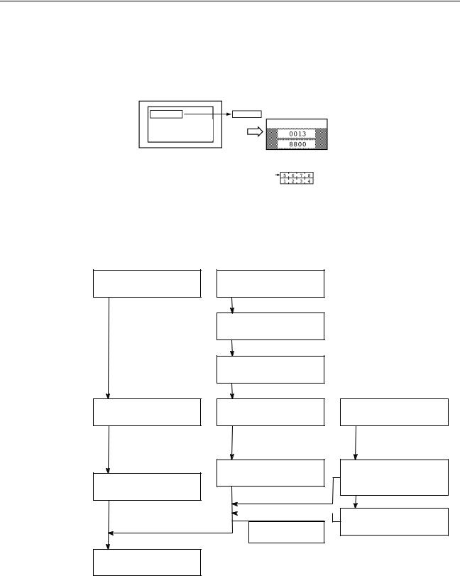
Functions of the PT Status Control Area (PLC to NT11)
The “PT status control area” is used to control the NT11 status. When data is written to this area in the PLC, the NT11 reads the contents and operates according to the contents.
[Example of the PT status control area application]
When data is written to the PT status control area, the NT11 will operate as given below.
|
|
|
|
Screen 3 |
|
|
|
|
|
|
|
|
NT11 |
|
PLC |
|
|
||
|
|
|
|
display |
|
|
|
||
|
|
|
|
|
|
PT status control area |
|||
|
|
|
|
|
|
|
|||
|
|
|
|
|
|
|
|||
|
|
|
|
|
|
|
|||
|
|
|
|
|
|
|
0003 |
Screen switch setting |
|
|
|
|
|
|
|
|
|||
|
|
|
|
|
|
|
0050 |
Memory table entry |
|
|
|
|
|
|
|
|
1007 |
Copy setting |
|
|
|
|
|
|
|
|
8010 |
PT status control bits |
|
|
|
|
|
|
|
|
|
|
|
|
|
|
Numeral memory table entry 50 |
|
|
|
|||
Copy |
Numeral memory table entry 7 |
|
|
|
|||||
Printing of daily reports or display histories
Functions of the PT Status Notify Area (NT11 to PLC)
The “PT status notify area” is used to notify the changes of the NT11 status.
When a change is made in the NT11 status, the change is written to this area in the PLC. By reading the data from the area, the NT11 status can be checked.
11
Before Operating |
Section 1-6 |
[Example of the PT status notify area application]
When a change is made in the NT11 status, such change will be notified to the PT status notify area as mentioned below.
|
NT11 |
|
PLC |
|
|
|
Numeral memory table entry 13 |
||
12345678 |
|
12345678 PT status notify area |
||
Currently display screen
Content update memory table entry
PT status
Allocated word (numeral table 13)
12345678 |
Start |
|
Start + 1 |
1-6 Before Operating
Follow the procedure given below to start the system of the NT11.
PLC |
|
NT11 |
|
Support tool |
Check and change the PLC settings.
For the host link, refer to page 22 and the manuals for the host link unit and peripheral tools.
For the NT link, refer to page 50.
Connect to the NT11.
Create the PLC program.
Start operation.
Set the DIP switches.
(page 18)
Install to the operation panel.
(page 19)
Connect the power supply.
(page 20)
Connect to the PLC.
(Host link: page 22)
(NT link: page 50)
Check the settings and communications.
Transfer the screen data.
(page 69)
Install the support tool in the computer.
Transfer the system program by using the system transfer tool.
Create the screens.
(refer to Section 4 and the manuals for the support tools)
12

Before Operating |
Section 1-6 |
Reference Use support tool NT-series Support Tool (NT-ZJCAT1-EV4.7).
!Caution Carefully check the operation of all screen data and host programs before using them.
Otherwise the system may operate unpredictably.
Refer to the following manuals for the equipment and software.
Device or Software |
Manual Title |
Cat. No. |
|
|
|
|
|
NT11 |
User’s Manual |
V084-E1-@ |
|
System Installer |
NT-series Support Tool for Windows (Ver. 4.7) Operation Manual |
V061-E1-@ |
|
NT Support Tool |
NT-series Support Tool for Windows (Ver. 4.7) Operation Manual |
V061-E1-@ |
|
PLC |
SYSMAC CPM1 Operation Manual |
W262-E1-@ |
|
|
SYSMAC CPM1A Operation Manual |
W317-E1-@ |
|
|
SYSMAC CPM2A Operation Manual |
W352-E1-@ |
|
|
SYSMAC CPM2C Operation Manual |
W356-E1-@ |
|
|
SYSMAC C200H Operation Manual (for CPU01/03/11) (Programming) |
W130-E1-@ |
|
|
SYSMAC C200H Operation Manual (for CPU21/23/31) (Programming) |
W217-E1-@ |
|
|
SYSMAC C200HS Installation Guide |
W236-E1-@ |
|
|
SYSMAC C200HS Operation Manual (Programming) |
W235-E1-@ |
|
|
SYSMAC C200HX/HG/HE (-Z) Installation Guide |
W302-E1-@ |
|
|
SYSMAC C200HX/HG/HE Operation Manual |
W303-E1-@ |
|
|
SYSMAC C200HX/HG/HE-Z Operation Manual |
W322-E1-@ |
|
|
SYSMAC CQM1/CPM1/CPM1A/SRM1 Programming Manual |
W228-E1-@ |
|
|
SYSMAC CQM1H Operation Manual |
W363-E1-@ |
|
|
SYSMAC CVM1/CV500/CV1000/CV2000/CVM1 Operation Manual: Ladder Dia- |
W202-E1-@ |
|
|
grams |
|
|
|
CS Series Programmable Controllers Operation Manual |
W339-E1-@ |
|
|
|
|
|
|
CJ Series CJ1G-CPU@@-E Programmable Controllers Operation Manual |
W393-E1-@ |
|
|
CS/CJ Series Programming Manual |
W394-E1-@ |
|
|
|
|
|
|
CS/CJ Series Serial Communications Boards/Units Operation Manual |
W336-E1-@ |
|
|
SYSMAC CQM1H Series Serial Communications Board Operation Manual |
W365-E1-@ |
|
|
|
|
|
CompoBus Master |
SRM1 (-V2) Operation Manual |
W318-E1-@ |
|
Control Unit |
|
|
|
|
|
|
|
Programming Tools |
SYSMAC Support Software Operation Manual: C-series PLCs |
W248-E1-@ |
|
|
|
|
|
|
SYSMAC Support Software Operation Manual: CVM1 PLCs |
W249-E1-@ |
|
|
|
|
|
|
SYSMAC CPT User Manual and Quick Start Guide |
W332-E1-@ |
|
|
|
W333-E1-@ |
|
|
CX-Programmer Ver. 4 User Manual |
W425-E1-@ |
|
Host Link Unit/ |
SYSMAC C Series Host Link Unit System Manual |
W143-E1-@ |
|
Serial Communica- |
|
|
|
SYSMAC CVM1/CV Series Host Link Operation Manual |
W205-E1-@ |
||
tions Board |
|||
SYSMAC C200HW-COM01 C200HW-COM02-V1 to C200HW-COM06-EV1 Com- |
W304-E1-@ |
||
|
|||
|
munications Board Operation Manual |
|
|
|
|
|
13

Before Operating |
Section 1-6 |
14
SECTION 2
Hardware Settings and Connections
This section describes the settings of the NT11, connections to a PLC, and other hardware settings.
2-1 Description of Parts and Settings . . . . . . . . . . . . . . . . . . . . . . . . . . . . . . . . . . |
16 |
||
|
2-1-1 |
Description of Parts . . . . . . . . . . . . . . . . . . . . . . . . . . . . . . . . . . . . . |
16 |
|
2-1-2 |
DIP Switch Settings . . . . . . . . . . . . . . . . . . . . . . . . . . . . . . . . . . . . . |
18 |
2-2 |
Installation. . . . . . . . . . . . . . . . . . . . . . . . . . . . . . . . . . . . . . . . . . . . . . . . . . . . |
19 |
|
|
2-2-1 Installation to the Operation Panel . . . . . . . . . . . . . . . . . . . . . . . . . . |
19 |
|
|
2-2-2 |
Power Supply Connection . . . . . . . . . . . . . . . . . . . . . . . . . . . . . . . . |
20 |
|
2-2-3 Wiring the Ground Wire . . . . . . . . . . . . . . . . . . . . . . . . . . . . . . . . . . |
21 |
|
2-3 Connecting to the NT Support Tool . . . . . . . . . . . . . . . . . . . . . . . . . . . . . . . . |
22 |
||
2-4 Connection to a PLC by the Host Link (RS-232C Type) . . . . . . . . . . . . . . . . |
22 |
||
|
2-4-1 |
Compatible PLCs . . . . . . . . . . . . . . . . . . . . . . . . . . . . . . . . . . . . . . . |
23 |
|
2-4-2 |
Connecting the NT11 . . . . . . . . . . . . . . . . . . . . . . . . . . . . . . . . . . . . |
24 |
|
2-4-3 |
PLC Switch Settings . . . . . . . . . . . . . . . . . . . . . . . . . . . . . . . . . . . . . |
27 |
2-5 Connection to a PLC by the Host Link (RS-422A Type) . . . . . . . . . . . . . . . . |
38 |
||
|
2-5-1 |
Compatible PLCs . . . . . . . . . . . . . . . . . . . . . . . . . . . . . . . . . . . . . . . |
38 |
|
2-5-2 Parts Required for Connection . . . . . . . . . . . . . . . . . . . . . . . . . . . . . |
40 |
|
|
2-5-3 |
Method for Connection. . . . . . . . . . . . . . . . . . . . . . . . . . . . . . . . . . . |
40 |
|
2-5-4 Connector Specifications and Wiring for Each Unit . . . . . . . . . . . . |
41 |
|
|
2-5-5 |
PLC Switch Settings . . . . . . . . . . . . . . . . . . . . . . . . . . . . . . . . . . . . . |
42 |
2-6 Connection to a PLC by the NT Link (RS-232C Type) . . . . . . . . . . . . . . . . . |
50 |
||
|
2-6-1 |
Compatible PLCs . . . . . . . . . . . . . . . . . . . . . . . . . . . . . . . . . . . . . . . |
50 |
|
2-6-2 |
Connecting the NT11 . . . . . . . . . . . . . . . . . . . . . . . . . . . . . . . . . . . . |
54 |
2-7 Connection to a PLC by the NT Link (RS-422A Type) . . . . . . . . . . . . . . . . . |
55 |
||
2-8 |
Connecting a Printer . . . . . . . . . . . . . . . . . . . . . . . . . . . . . . . . . . . . . . . . . . . . |
57 |
|
|
2-8-1 |
How to Connect . . . . . . . . . . . . . . . . . . . . . . . . . . . . . . . . . . . . . . . . |
57 |
15
Description of Parts and Settings |
Section 2-1 |
2-1 Description of Parts and Settings
Before getting to the operation, confirm the names and functions of parts.
Also set the DIP switches on the NT11.
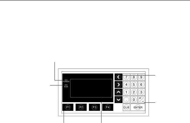
2-1-1 Description of Parts
Front View
POWER LED
Lit when the power is supplied.
RUN LED
Lit when the communication status is normal.
Function keys
Used for direct notifications to the PLC.
Display
An LCD screen with a backlight.
Arrow keys
Used to select the required numerical value input field when there is more than one on the screen.
Numeric keys
Used for inputting numerical values on screens that require numerical value input.
Reference The NT11 comes in two body colors.
•NT11-SF121-EV1:Beige
•NT11-SF121B-EV1:Black
16
|
Description of Parts and Settings |
|
|
|
|
|
|
|
Section 2-1 |
||||||||||||||||
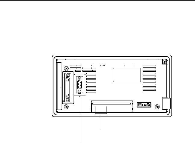
Rear View |
|
|
|
|
|
|
|
|
|||||||||||||||||
|
Connector for parallel interface connection |
Contrast control |
|||||||||||||||||||||||
|
Connect the printer cable here. |
Use a fine phillips screwdriver. |
|||||||||||||||||||||||
|
(Interface conforms to Centronics specifications) |
Turn clockwise to increase the brightness. |
|||||||||||||||||||||||
|
|
|
|
|
|
|
|
|
|
|
|
|
|
|
|
|
|
|
|
|
DIP switch |
||||
|
|
|
|
|
|
|
|
|
|
|
|
|
|
|
|
|
|
|
|
|
|||||
|
|
|
|
|
|
|
|
|
|
|
|
|
|
|
|
|
|
|
|
|
Set various system statuses |
||||
|
|
|
|
|
|
|
|
|
|
|
|
|
|
|
|
|
|
|
|
|
with these switches. |
||||
|
|
|
|
|
|
|
|
|
|
|
|
|
|
|
|
|
|
|
|
|
|
|
|
|
|
|
|
|
|
|
|
|
|
|
|
|
|
|
|
|
|
|
|
|
|
|
|
|
|
|
|
|
|
|
|
|
|
|
|
|
|
|
|
|
|
|
|
|
|
|
|
|
|
|
|
|
|
|
|
|
|
|
|
|
|
|
|
|
|
|
|
|
|
|
|
|
|
|
|
|
|
|
|
|
|
|
|
|
|
|
|
|
|
|
|
|
|
|
|
|
|
|
|
|
|
|
|
|
|
|
|
|
|
|
|
|
|
|
|
|
|
|
|
|
|
|
|
|
|
|
|
|
|
|
|
|
|
|
|
|
|
|
|
|
|
|
|
|
|
|
|
|
|
|
|
|
|
|
|
|
|
|
|
|
|
|
|
|
|
|
|
|
|
|
|
|
|
|
|
|
|
|
|
|
|
|
|
|
|
|
|
|
|
|
|
|
|
|
|
|
|
|
|
|
|
|
|
|
|
|
|
|
|
|
|
|
|
|
|
|
|
|
|
|
|
|
|
|
|
|
|
|
|
|
|
|
|
|
|
|
|
|
|
|
|
|
|
|
|
|
|
|
|
|
|
|
|
|
|
|
|
|
|
|
|
|
|
|
|
|
|
|
|
|
|
|
|
|
|
|
|
|
|
|
|
|
|
|
|
|
|
|
|
|
|
|
|
|
|
|
|
|
|
|
|
|
|
|
|
|
|
|
|
|
|
|
|
|
|
|
|
|
|
|
|
|
|
|
|
|
|
|
|
|
|
|
|
|
|
|
|
|
|
|
|
|
|
|
|
|
|
|
|
|
|
|
|
|
|
|
|
|
|
|
|
|
|
|
|
|
|
|
|
|
|
|
|
|
|
|
|
|
|
|
|
|
|
|
|
|
|
|
|
|
|
RS-422A terminal block
Connect the PLC cable here.
Power input terminals
Connect the power to the
NT11 at these terminals.
RS-232C connector
Connect the cable that connects the PLC or support tool here.
17
Loading...