


 Loading...
Cat. No. I203-E2-02
R88A-MCW151-E
R88A-MCW151-DRT-E
Motion Control Option
Board
OPERATION MANUAL
MCW151 Series
Motion Control Option Board
Models: R88A-MCW151-E
R88A-MCW151-DRT-E
Operation Manual
Produced March 2003
Notice:
OMRON products are manufactured for use according to proper procedures by a qualified operator and only for the purposes described in this manual.
The following conventions are used to indicate and classify precautions in this manual. Always heed the information provided with them. Failure to heed precautions can result in injury to people or damage to property.
!DANGER Indicates an imminently hazardous situation which, if not avoided, will result in death or serious injury.
!WARNING Indicates a potentially hazardous situation which, if not avoided, could result in death or serious injury.
!Caution Indicates a potentially hazardous situation which, if not avoided, may result in minor or moderate injury, or property damage.
OMRON Product References
All OMRON products are capitalized in this manual. The word “Unit” is also capitalized when it refers to an OMRON product, regardless of whether or not it appears in the proper name of the product.
The abbreviation “Ch”, which appears in some displays and on some OMRON products, often means “word” and is abbreviated “Wd” in documentation in this sense.
The abbreviation “PC” means Programmable Controller and is not used as an abbreviation for anything else.
Visual Aids
The following headings appear in the left column of the manual to help you locate different types of information.
Note Indicates information of particular interest for efficient and convenient operation of the product.
1,2,3... Indicates lists of one sort or another, such as procedures, checklists, etc.
Trademarks and Copyrights
DeviceNet is a registered trademark of the Open DeviceNet Vendor Association, Inc.
OMRON, 2003
All rights reserved. No part of this publication may be reproduced, stored in a retrieval system, or transmitted, in any form, or by any means, mechanical, electronic, photocopying, recording, or otherwise, without the prior written permission of OMRON.
No patent liability is assumed with respect to the use of the information contained herein. Moreover, because OMRON is constantly striving to improve its high-quality products, the information contained in this manual is subject to change without notice. Every precaution has been taken in the preparation of this manual. Nevertheless, OMRON assumes no responsibility for errors or omissions. Neither is any liability assumed for damages resulting from the use of the information contained in this publication.
v
vi

About this Manual:
This manual describes the installation and operation of the R88A-MCW151-E and R88A-MCW151- DRT-E Motion Control Option Boards (MC Units) and includes the sections described below.
Please read this manual and the related manuals listed in the following table carefully and be sure you understand the information provided before attempting to install or operate the MC Unit. Be sure to read the precautions provided in the following section.
Name |
Cat. No. |
Contents |
|
|
|
MCW151 Series |
I203 |
Describes the installation and operation of the R88A-MCW151-E |
R88A-MCW151-E |
|
and MCW151-DRT-E Motion Control Units. |
R88A-MCW151-DRT-E |
|
(This manual) |
Operation Manual |
|
|
|
|
|
OMNUC W-series |
I531 |
Describes the installation and operation of the W-series Servo Driver |
R88M-W (AC Servomotors) |
|
and Servomotor. |
R88D-W (AC Servo Drivers) |
|
|
User’s manual |
|
|
|
|
|
DeviceNet Operation Manual |
W267 |
Describes the configuration and construction of a DeviceNet net- |
|
|
work, including installation procedures and specifications for cables, |
|
|
connectors, and other connection devices, as well as information on |
|
|
the communications power supply. |
|
|
|
DeviceNet Configurator Oper- |
W328 |
Describes the operation of the DeviceNet Configurator to allocate |
ation Manual |
|
remote I/O areas according to application needs, as well as proce- |
|
|
dures to set up a DeviceNet network with more than one master. |
|
|
|
Precautions provides general precautions for using the MC Unit and related devices.
Section 1 describes the features and system configuration of the R88A-MCW151-E and R88A- MCW151-DRT-E Motion Control Units and concepts related to their operation.
Section 2 describes the MC Unit components and provides the information for installing the MC Unit. Section 3 describes the different Motion Control features of the MCW151. Also the functionality of the Servo Driver related commands are explained.
Section 4 describes the communication components of the MCW151-E and MCW151-DRT-E. The functionality of the serial communication protocols and the DeviceNet interface are explained. Section 5 provides an overview of the fundamentals of multitasking BASIC programs and the methods by which programs are managed in the MC Unit.
Section 6 describes all commands, functions and parameters required for programing the motion control application using the MC Unit.
Section 7 describes the operation of the Motion Perfect programming software package. Motion Perfect provides the user a tool to program, monitor and debug motion based applications for the MC Unit. Section 8 describes error processing and troubleshooting procedures needed to keep the system operating properly.
Section 9 explains the maintenance and inspection procedures that must be followed to keep the MC Unit operating in optimum condition. It also includes proper procedures when replacing an MC Unit. The Appendices provide the required parameter settings for the Servo Driver, the DeviceNet protocol specification and some general programming examples.
!WARNING Failure to read and understand the information provided in this manual may result in personal injury or death, damage to the product, or product failure. Please read each section in its entirety and be sure you understand the information provided in the section and related sections before attempting any of the procedures or operations given.
vii
TABLE OF CONTENTS
PRECAUTIONS . . . . . . . . . . . . . . . . . . . . . . . . . . . . . . . . |
xi |
||
1 |
|
Intended Audience . . . . . . . . . . . . . . . . . . . . . . . . . . . . . . . . . . . . . . . . . . . . . . . . . |
xii |
2 |
|
General Precautions . . . . . . . . . . . . . . . . . . . . . . . . . . . . . . . . . . . . . . . . . . . . . . . . |
xii |
3 |
General Warnings and Safety Precautions . . . . . . . . . . . . . . . . . . . . . . . . . . . . . . . |
xii |
|
4 |
Storage and Transportation Precautions . . . . . . . . . . . . . . . . . . . . . . . . . . . . . . . . . |
xiv |
|
5 |
|
Installation and Wiring Precautions . . . . . . . . . . . . . . . . . . . . . . . . . . . . . . . . . . . . |
xiv |
6 |
|
Operation and Adjustment Precautions. . . . . . . . . . . . . . . . . . . . . . . . . . . . . . . . . . |
xv |
7 |
|
Maintenance and Inspection Precautions . . . . . . . . . . . . . . . . . . . . . . . . . . . . . . . . |
xv |
8 |
|
Conformance to EC Directives . . . . . . . . . . . . . . . . . . . . . . . . . . . . . . . . . . . . . . . . |
xv |
SECTION 1 |
|
||
Features and System Configuration . . . . . . . . . . . . . . . . |
1 |
||
1-1 |
Features . . . . . . . . . . . . . . . . . . . . . . . . . . . . . . . . . . . . . . . . . . . . . . . . . . . . . . . . . . |
2 |
|
1-2 |
System Configuration . . . . . . . . . . . . . . . . . . . . . . . . . . . . . . . . . . . . . . . . . . . . . . . |
5 |
|
1-3 |
Motion Control Concepts . . . . . . . . . . . . . . . . . . . . . . . . . . . . . . . . . . . . . . . . . . . . |
7 |
|
1-4 |
Control System Configuration . . . . . . . . . . . . . . . . . . . . . . . . . . . . . . . . . . . . . . . . |
14 |
|
1-5 |
Specifications . . . . . . . . . . . . . . . . . . . . . . . . . . . . . . . . . . . . . . . . . . . . . . . . . . . . . |
19 |
|
1-6 Comparison between Firmware Versions . . . . . . . . . . . . . . . . . . . . . . . . . . . . . . . . |
21 |
||
SECTION 2 |
|
||
Installation . . . . . . . . . . . . . . . . . . . . . . . . . . . . . . . . . . . . . |
23 |
||
2-1 Components and Unit Settings . . . . . . . . . . . . . . . . . . . . . . . . . . . . . . . . . . . . . . . . |
24 |
||
2-2 |
Installation. . . . . . . . . . . . . . . . . . . . . . . . . . . . . . . . . . . . . . . . . . . . . . . . . . . . . . . . |
28 |
|
2-3 |
Wiring . . . . . . . . . . . . . . . . . . . . . . . . . . . . . . . . . . . . . . . . . . . . . . . . . . . . . . . . . . . |
30 |
|
2-4 |
Servo System Precautions . . . . . . . . . . . . . . . . . . . . . . . . . . . . . . . . . . . . . . . . . . . . |
39 |
|
2-5 |
Wiring Precautions . . . . . . . . . . . . . . . . . . . . . . . . . . . . . . . . . . . . . . . . . . . . . . . . . |
40 |
|
SECTION 3 |
|
||
Motion Control Functions . . . . . . . . . . . . . . . . . . . . . . . . |
43 |
||
3-1 |
Overview . . . . . . . . . . . . . . . . . . . . . . . . . . . . . . . . . . . . . . . . . . . . . . . . . . . . . . . . . |
44 |
|
3-2 |
System Set-up . . . . . . . . . . . . . . . . . . . . . . . . . . . . . . . . . . . . . . . . . . . . . . . . . . . . . |
46 |
|
3-3 |
System Functions . . . . . . . . . . . . . . . . . . . . . . . . . . . . . . . . . . . . . . . . . . . . . . . . . . |
47 |
|
SECTION 4 |
|
||
Communication Interfaces . . . . . . . . . . . . . . . . . . . . . . . . |
59 |
||
4-1 |
Serial Communications . . . . . . . . . . . . . . . . . . . . . . . . . . . . . . . . . . . . . . . . . . . . . . |
60 |
|
4-2 |
DeviceNet (MCW151-DRT-E only) . . . . . . . . . . . . . . . . . . . . . . . . . . . . . . . . . . . . |
68 |
|
ix
TABLE OF CONTENTS
SECTION 5 |
|
|
Multitasking BASIC Programming. . . . . . . . . . . . . . . . . |
85 |
|
5-1 |
Overview . . . . . . . . . . . . . . . . . . . . . . . . . . . . . . . . . . . . . . . . . . . . . . . . . . . . . . . . |
86 |
5-2 |
BASIC Programming. . . . . . . . . . . . . . . . . . . . . . . . . . . . . . . . . . . . . . . . . . . . . . . |
86 |
5-3 |
Motion Execution . . . . . . . . . . . . . . . . . . . . . . . . . . . . . . . . . . . . . . . . . . . . . . . . . |
89 |
5-4 |
Command Line Interface . . . . . . . . . . . . . . . . . . . . . . . . . . . . . . . . . . . . . . . . . . . . |
90 |
5-5 |
BASIC Programs . . . . . . . . . . . . . . . . . . . . . . . . . . . . . . . . . . . . . . . . . . . . . . . . . . |
90 |
5-6 |
Task Operation Sequence . . . . . . . . . . . . . . . . . . . . . . . . . . . . . . . . . . . . . . . . . . . |
93 |
5-7 |
Error Processing. . . . . . . . . . . . . . . . . . . . . . . . . . . . . . . . . . . . . . . . . . . . . . . . . . . |
94 |
SECTION 6 |
|
|
BASIC Motion Control Programming Language . . . . . |
97 |
|
6-1 |
Overview . . . . . . . . . . . . . . . . . . . . . . . . . . . . . . . . . . . . . . . . . . . . . . . . . . . . . . . . |
102 |
6-2 |
Command Reference List . . . . . . . . . . . . . . . . . . . . . . . . . . . . . . . . . . . . . . . . . . . |
103 |
6-3 Command, function and parameter description. . . . . . . . . . . . . . . . . . . . . . . . . . . |
111 |
|
SECTION 7 |
|
|
Motion Perfect Software Package . . . . . . . . . . . . . . . . . . |
197 |
|
7-1 |
Features and Requirements . . . . . . . . . . . . . . . . . . . . . . . . . . . . . . . . . . . . . . . . . . |
198 |
7-2 Connecting to the MC Unit . . . . . . . . . . . . . . . . . . . . . . . . . . . . . . . . . . . . . . . . . . |
198 |
|
7-3 |
Motion Perfect Projects . . . . . . . . . . . . . . . . . . . . . . . . . . . . . . . . . . . . . . . . . . . . . |
199 |
7-4 |
Desktop Appearance . . . . . . . . . . . . . . . . . . . . . . . . . . . . . . . . . . . . . . . . . . . . . . . |
201 |
7-5 |
Motion Perfect Tools . . . . . . . . . . . . . . . . . . . . . . . . . . . . . . . . . . . . . . . . . . . . . . . |
204 |
7-6 |
Suggestions and Precautions . . . . . . . . . . . . . . . . . . . . . . . . . . . . . . . . . . . . . . . . . |
217 |
SECTION 8 |
|
|
Troubleshooting. . . . . . . . . . . . . . . . . . . . . . . . . . . . . . . . . |
219 |
|
8-1 |
Error Indicators . . . . . . . . . . . . . . . . . . . . . . . . . . . . . . . . . . . . . . . . . . . . . . . . . . . |
220 |
8-2 |
Error Handling . . . . . . . . . . . . . . . . . . . . . . . . . . . . . . . . . . . . . . . . . . . . . . . . . . . . |
221 |
8-3 |
Problems and Countermeasures. . . . . . . . . . . . . . . . . . . . . . . . . . . . . . . . . . . . . . . |
227 |
SECTION 9 |
|
|
Maintenance and Inspection. . . . . . . . . . . . . . . . . . . . . . . |
233 |
|
9-1 |
Routine Inspections . . . . . . . . . . . . . . . . . . . . . . . . . . . . . . . . . . . . . . . . . . . . . . . . |
234 |
9-2 Replacing a MC Unit . . . . . . . . . . . . . . . . . . . . . . . . . . . . . . . . . . . . . . . . . . . . . . . |
235 |
|
Appendices |
|
|
Appendix A Servo Driver Parameter List . . . . . . . . . . . . . . . . . . . . . . . . . . . . . . . . . |
237 |
|
Appendix B Device Protocol (MCW151-DRT-E only). . . . . . . . . . . . . . . . . . . . . . . |
239 |
|
Appendix C Programming Examples. . . . . . . . . . . . . . . . . . . . . . . . . . . . . . . . . . . . . |
245 |
|
Index . . |
. . . . . . . . . . . . . . . . . . . . . . . . . . . . . . . . . . . . . . . . |
255 |
Revision History . . . . . . . . . . . . . . . . . . . . . . . . . . . . . . . . |
261 |
|
x
PRECAUTIONS
This section provides general precautions for using the Motion Control Unit and related devices.
The information contained in this section is important for the safe and reliable application of the Motion Control Unit. You must read this section and understand the information contained before attempting to set up or operate a Motion Control Unit and Servo Driver.
1 |
Intended Audience . . . . . . . . . . . . . . . . . . . . . . . . . . . . . . . . . . . . . . . . . . . . . |
xii |
|
2 |
General Precautions . . . . . . . . . . . . . . . . . . . . . . . . . . . . . . . . . . . . . . . . . . . . |
xii |
|
3 |
General Warnings and Safety Precautions . . . . . . . . . . . . . . . . . . . . . . . . . . . |
xii |
|
4 |
Storage and Transportation Precautions . . . . . . . . . . . . . . . . . . . . . . . . . . . . . |
xiv |
|
5 |
Installation and Wiring Precautions . . . . . . . . . . . . . . . . . . . . . . . . . . . . . . . . |
xiv |
|
6 |
Operation and Adjustment Precautions. . . . . . . . . . . . . . . . . . . . . . . . . . . . . . |
xv |
|
7 |
Maintenance and Inspection Precautions . . . . . . . . . . . . . . . . . . . . . . . . . . . . |
xv |
|
8 |
Conformance to EC Directives . . . . . . . . . . . . . . . . . . . . . . . . . . . . . . . . . . . . |
xv |
|
|
8-1 |
Concepts . . . . . . . . . . . . . . . . . . . . . . . . . . . . . . . . . . . . . . . . . . . . . . |
xvi |
|
8-1-1 |
Conformance to EC Directives . . . . . . . . . . . . . . . . . . . . . . . . . . . . . |
xvi |
xi
Intended Audience |
1 |
1 Intended Audience
This manual is intended for the following personnel, who must also have knowledge of electrical systems (an electrical engineer or the equivalent).
•Personnel in charge of installing FA systems.
•Personnel in charge of designing FA systems.
•Personnel in charge of managing FA systems and facilities.
2 General Precautions
The user must operate the product according to the performance specifications described in the operation manuals. You should assume that anything not described in this manual is not possible.
Before using the product under the following conditions, consult your OMRON representative, make sure the ratings and performance characteristics of the products are good enough for the systems, machines, or equipment, and be sure to provide the systems, machines, or equipment with double safety mechanisms.
1.Conditions not described in the manual.
2.The application of the product to nuclear control systems, railroad systems, aviation systems, vehicles, combustion systems, medical equipment, amusement machines, or safety equipment.
3.The application of the product to systems, machines, or equipment that may have a serious influence on human life and property if they are used improperly.
!WARNING It is extremely important that Motion Control Units and related devices be used for the specified purpose and under the specified conditions, especially in applications that can directly or indirectly affect human life. You must consult with your OMRON representative before applying Motion Control Units and related devices to the above mentioned applications.
3 General Warnings and Safety Precautions
Observe the following warnings when using the MC Unit and all pheripheral devices. Consult your OMRON representative when using the product after a long period of storage.
!WARNING Always connect the frame ground terminals of the Servo Driver and the Servomotor to a class-3 ground (to 100 Ω or less). Not connecting to a class-3 ground may result in electric shock.
!WARNING The product contains dangerous high voltage inside. Turn OFF the power and wait for at least five minutes to allow power to discharge before handling or working with the product.
!WARNING
!WARNING
!WARNING
!WARNING
!WARNING
Do not touch the inside of the Servo Driver. Doing so may result in electric shock.
Do not remove the front cover, terminal covers, cables, Parameter Units, or optional items while the power is being supplied. Doing so may result in electric shock.
Installation, operation, maintenance, or inspection must be performed by authorized personnel. Not doing so may result in electric shock or injury.
Wiring or inspection must not be performed for at least five minutes after turning OFF the power supply. Doing so may result in electric shock.
Do not damage, press, or put excessive stress or heavy objects on the cables. Doing so may result in electric shock, stopping operation of the product, or burning.
xii

General Warnings and Safety Precautions |
3 |
!WARNING
!WARNING
!WARNING
!WARNING
Do not touch the rotating parts of the Servomotor in operation. Doing so may result in injury.
Do not modify the product. Doing so may result in injury or damage to the product.
Provide safety measures in external control circuits (i.e., not in the MC Unit) to ensure safety in the system if an abnormality occurs due to malfunction of the MC Unit, incorrect or unintended configuration and programming of the MC Unit or external factors affecting the operation of the MC Unit. Not providing sufficient safety measures may result in serious accidents, or property damage.
•The MC Unit outputs may remain ON or OFF due to deposits on or burning of the output relays, or destruction of the output transistors. As a counter-measure for such problems, external safety measures must be provided to ensure safety in the system.
•Provide an external emergency stopping device that allows an instantaneous stop of operation and power interruption. Not doing so may result in injury.
•Emergency stop circuits, interlock circuits, limit circuits, and similar safety measures must be provided in external control circuits.
•When the 24-VDC output (service power supply to the Unit) is overloaded or short-cir- cuited, the voltage may drop and result in the outputs being turned OFF. As a countermeasure for such problems, external safety measures must be provided to ensure safety in the system.
It is the nature of high speed motion control and motion control language programming and multi-tasking systems, that it is not always possible for the system to validate the inputs to the functions or to validate the combination of functions.
!WARNING It is the responsibility of the programmer to ensure that the various BASIC statements are invoked correctly with the correct number of parameters and inputs, that the values are correctly validated prior to the actual calling of the functions, and that the BASIC program(s) provide the desired functionality for the application. Failure to do so may result in unexpected behaviour, loss or damage to the machinery.
!Caution When the SERVO_PERIOD parameter has been set to change the servo cycle period of the MC Unit, a power down or software reset (using DRV_RESET) must be performed for the complete system. Not doing so may result in undefined behaviour.
!Caution Use the Servomotors and Servo Drivers in a specified combination. Using them incorrectly may result in fire or damage to the product.
!Caution Do not operate the control system in the following locations:
•Locations subject to direct sunlight.
•Locations subject to temperatures or humidity outside the range specified in the specifications.
•Locations subject to condensation due to radical temperature changes.
•Locations subject to corrosive or inflammable gases.
•Locations subject to dust (especially iron dust) or salts.
•Locations subject to vibration or shock.
•Locations subject to exposure to water, oil or chemicals.
!Caution Do not touch the Servo Driver radiator, Regeneration Resistor, or Servomotor while the power is being supplied or soon after power is turned OFF. Doing so may result in a skin burn due to the hot surface.
xiii

Storage and Transportation Precautions |
4 |
4 Storage and Transportation Precautions
!Caution Do not hold the product by the cables or motor shaft while transporting it. Doing so may result in injury or malfunction.
!Caution Do not place any load exceeding the figure indicated on the product. Doing so may result in injury or malfunction.
!Caution Use the motor eye-bolts only for transporting the Motor. Using them for transporting the machinery may result in injury or malfunction.
5 Installation and Wiring Precautions
!Caution Do not step or place a heavy object on the product. Doing so may result in injury.
!Caution Do not cover the inlet or outlet ports and prevent any foreign objects from entering the product. Doing so may result in fire.
!Caution Be sure to install the product in the right direction. Not doing so may result in malfunction.
!Caution Provide the specified clearance between the Servo Driver and the control panel or with other devices. Not doing so may result in fire or malfunction.
!Caution Do not apply any strong impact. Doing so may result in malfunction.
!Caution Be sure to wire correctly and securely. Not doing so may result in motor runaway, injury, or malfunction.
!Caution Be sure that all mounting screws, terminal screws, and cable connector screws are tightened securely. Incorrect tightening may result in malfunction.
!Caution Use crimp terminals for wiring. Do not connect bare stranded wires directly to terminals. Connection of bare stranded wires may result in fire.
!Caution Always use the power supply voltages specified in the manual. An incorrect voltage may result in malfunction or burning.
!Caution Take appropriate measures to ensure that the specified power with the rated voltage and frequency is supplied. Be particularly careful in places where the power supply is unstable. An incorrect power supply may result in malfunction.
!Caution Install external breakers and take other safety measures against short-circuiting in external wiring. Insufficient safety measures against short-circuiting may result in burning.
!Caution Take appropriate and sufficient countermeasures when installing systems in the following locations. Not doing so may result in damage to the product.
•Locations subject to static electricity or other sources of noise.
•Locations subject to strong electromagnetic fields.
•Locations subject to possible exposure to radiation.
•Locations near power supply lines.
!Caution Do not reverse the polarity of the battery when connecting it. Reversing the polarity may damage the battery or cause it to explode.
!Caution Before touching a Unit, be sure to first touch a grounded metallic object in order to discharge any static build-up. Not doing so may result in malfunction or damage.
xiv

Operation and Adjustment Precautions |
6 |
6 Operation and Adjustment Precautions
!Caution Confirm that no adverse effects will occur in the system before performing the test operation. Not doing so may result in damage to the product.
!Caution Check the modified user programs, newly set parameters and switches for proper execution before actually running them. Not doing so may result in damage to the product.
!Caution Do not make any extreme adjustments or setting changes. Doing so may result in unstable operation and injury.
!Caution Separate the Servomotor from the machine, check for proper operation, and then connect to the machine. Not doing so may cause injury.
!Caution When an alarm occurs, remove the cause, reset the alarm after confirming safety, and then resume operation. Not doing so may result in injury.
!Caution Do not come close to the machine immediately after resetting momentary power interruption to avoid an unexpected restart. (Take appropriate measures to secure safety against an unexpected restart.) Doing so may result in injury.
!Caution Confirm that no adverse effect will occur in the system before attempting any of the following. Not doing so may result in an unexpected operation or damage to the product.
•Changing the present values or set values.
•Changing the parameters.
•Modifying (one of) the application programs.
!Caution Do not save data into the flash memory during memory operation or while the motor is running. Otherwise, unexpected operation may be caused.
!Caution Do not turn OFF the power supply to the Unit while data is being written to flash memory. Doing so may cause problems with the flash memory.
!Caution Do not turn OFF the power supply to the Unit while data is being transferred. Doing so may result in malfunction or damage to the product.
!Caution Do not download any firmware to the MC Unit that has not been distributed by OMRON or that has not been authorized and approved by OMRON for downloading into the MCW151 series. Failure to do so may result in permanent or temporary malfunction of the Unit or unexpected behaviour.
7 Maintenance and Inspection Precautions
!WARNING Do not attempt to disassemble, repair, or modify any Units. Any attempt to do so may result in malfunction, fire, electric shock, or injury.
!Caution Resume operation only after transferring to the new Unit the contents of the data required for operation. Not doing so may result in an unexpected operation or damage to the product.
8 Conformance to EC Directives
Applicable Directives
•EMC Directives
•Low Voltage Directive
xv

Conformance to EC Directives |
8 |
8-1 Concepts
EMC Directives
OMRON devices that comply with EC Directives also conform to the related EMC standards so that they can be more easily built into other devices or ma-chines. The actual products have been checked for conformity to EMC standards (see the following note). Whether the products conform to the standards in the system used by the customer, however, must be checked by the customer. EMC-related performance of the OMRON devices that comply with EC Directives will vary depending on the configuration, wiring, and other conditions of the equipment or control panel in which the OMRON devices are installed. The customer must, therefore, perform final checks to confirm that devices and the over-all machine conform to EMC standards.
Note Applicable EMC (Electromagnetic Compatibility) standards are as follows:
EMS (Electromagnetic Susceptibility): |
EN61000-6-2, EN50082-2 |
EMI (Electromagnetic Interference): |
EN55011 Class A Group 1 |
Low Voltage Directive
Always ensure that devices operating at voltages of 50 to 1,000 VAC or 75 to 1,500 VDC meet the required safety standards.
8-1-1 Conformance to EC Directives
The W-series Servo Driver complies with EC Directives. To ensure that the machine or device in which a Servo Driver and MC Unit are used complies with EC directives, the Servo System must be installed as follows (refer to OMNUC W-series User’s manual (I531)):
1,2,3... 1. The Servo Driver must be mounted in a metal case (control box). (It is not necessary to mount the Servomotor in a metal box.)
2.Noise filters and surge absorbers must be inserted in power supply lines.
3.Shielded cable must be used for I/O signal cables and encoder cables. (Use soft steel wire.)
4.Cables leading out from the control box must be enclosed within metal ducts or conduits with blades.
5.Ferrite cores must be installed for cables with braided shields, and the shield must be directly grounded to a ground plate.
xvi
SECTION 1
Features and System Configuration
This section describes the features and system configuration of the R88A-MCW151-E and R88A-MCW151-DRT-E
Motion Control Units and concepts related to their operation. |
|
||
1-1 |
Features |
. . . . . . . . . . . . . . . . . . . . . . . . . . . . . . . . . . . . . . . . . . . . . . . . . . . . . . |
2 |
|
1-1-1 |
Overview. . . . . . . . . . . . . . . . . . . . . . . . . . . . . . . . . . . . . . . . . . . . . . |
2 |
|
1-1-2 |
Description of Features. . . . . . . . . . . . . . . . . . . . . . . . . . . . . . . . . . . |
3 |
1-2 |
System Configuration . . . . . . . . . . . . . . . . . . . . . . . . . . . . . . . . . . . . . . . . . . . |
5 |
|
1-3 |
Motion Control Concepts . . . . . . . . . . . . . . . . . . . . . . . . . . . . . . . . . . . . . . . . |
7 |
|
|
1-3-1 |
PTP-control . . . . . . . . . . . . . . . . . . . . . . . . . . . . . . . . . . . . . . . . . . . . |
8 |
|
1-3-2 |
CP-control. . . . . . . . . . . . . . . . . . . . . . . . . . . . . . . . . . . . . . . . . . . . . |
10 |
|
1-3-3 |
EG-Control . . . . . . . . . . . . . . . . . . . . . . . . . . . . . . . . . . . . . . . . . . . . |
11 |
|
1-3-4 |
Other Operations. . . . . . . . . . . . . . . . . . . . . . . . . . . . . . . . . . . . . . . . |
13 |
1-4 |
Control System Configuration . . . . . . . . . . . . . . . . . . . . . . . . . . . . . . . . . . . . |
14 |
|
|
1-4-1 |
Servo System Principles . . . . . . . . . . . . . . . . . . . . . . . . . . . . . . . . . . |
14 |
|
1-4-2 |
Encoder Signals . . . . . . . . . . . . . . . . . . . . . . . . . . . . . . . . . . . . . . . . |
17 |
1-5 |
Specifications . . . . . . . . . . . . . . . . . . . . . . . . . . . . . . . . . . . . . . . . . . . . . . . . . |
19 |
|
|
1-5-1 |
General Specifications . . . . . . . . . . . . . . . . . . . . . . . . . . . . . . . . . . . |
19 |
|
1-5-2 |
Functional Specifications . . . . . . . . . . . . . . . . . . . . . . . . . . . . . . . . . |
19 |
|
1-5-3 DeviceNet Specifications (MCW151-DRT-E only) . . . . . . . . . . . . . |
21 |
|
1-6 Comparison between Firmware Versions . . . . . . . . . . . . . . . . . . . . . . . . . . . . |
21 |
||
1
Features Section 1-1
1-1 Features
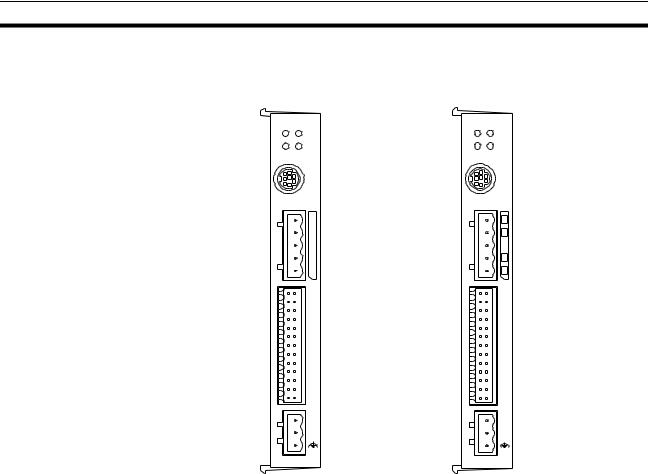
MCW151-E |
MCW151-DRT-E |
||
M CW151 |
MCW151-DRT |
||
RUN |
STS |
RUN |
STS |
SD |
RD |
MS |
NS |
|
PORT0,1 |
|
PORT0,1 |
|
PORT2 |
|
|
1 |
2 |
1 |
2 |
|
I/O |
|
I/O |
2 5 |
26 |
2 5 |
26 |
|
+ 24 V |
|
+ 2 4V |
|
0 V |
|
0V |
1-1-1 |
Overview |
|
|
|
|
The R88A-MCW151 is a 1.5-axis Motion Control (MC) Unit which is con- |
|
|
|
nected to the W-series Servo Driver. The MC Unit provides direct control of |
|
|
|
the Servo Driver, enables both speed and torque control and has access to |
|
|
|
detailed Servo Driver data. To support a multi-axis control application, the MC |
|
|
|
Unit features both an encoder input and output connection. |
|
|
|
There are two types of the MCW151 Motion Controllers, according to the |
|
|
|
communication interface which is integrated into the Unit. |
|
|
|
|
|
|
|
Communication Interface |
Model |
|
|
|
|
|
|
RS-422A/485 Serial Communication |
R88A-MCW151-E |
|
|
|
|
|
|
DeviceNet |
R88A-MCW151-DRT-E |
|
|
|
|
|
|
The multi-tasking BASIC motion control language provides an easy to use |
|
|
|
tool for programming advanced motion control applications. |
|
|
|
Three types of motion control are possible: point-to-point, continuous path |
|
|
|
and electronic gearing. |
|
Point-to-point Control |
Point-to-point (PTP) control enables positioning independently for each axis. |
||
|
|
Axis specific parameters and commands are used to determine the paths for |
|
|
|
the axes. |
|
Continuous Path Control |
Continuous path (CP) control enables the user not only to control the start and |
||
|
|
end positions, but also the path between those points. Possible multi-axis |
|
|
|
paths are linear interpolation and circular interpolation. Also user defined |
|
|
|
paths can be realized with the CAM control. |
|
Electronic Gearing |
Electronic gearing (EG) enables controlling an axis as a direct link to another |
||
|
|
axis. The MC Units supports electronic gear boxing, linked moves and CAM |
|
|
|
movements and adding all movements of one axis to another. |
|
2

Features |
Section 1-1 |
1-1-2 Description of Features
|
The MC Unit provides the following features. |
Motion Control |
The direct connection to the Servo Driver provides a high performance / high |
|
precision control system. Operation will be processed in optimal synchroniza- |
|
tion. |
|
• Supports both speed and torque control modes of the Servo Driver. |
|
• Supports switching between the modes during operation. |
|
• Supports speed limit during torque control using the speed reference. |
|
• Selectable MC Unit servo period cycle which can be set to either 0.5 ms |
|
or 1.0 ms. |
Servo Driver Access |
Apart from the motion control operation with the Servo Driver, the MC Unit |
|
provides the following features: |
|
• Monitor the detailed Servo Driver alarm status. |
|
• Monitor various monitor signals (rotation speed, command torque). |
|
• Monitor the Servo Driver digital inputs and analog input to include in the |
|
application. |
|
• Read and write of the Servo Driver Parameters. |
|
• Execution of several Driver functions from the MC Unit. Examples are |
|
Print Registration, Origin Search, Driver Alarm Reset and Driver Reset. |
Easy Programming with |
The multi-task BASIC motion control language is used to program the MC |
BASIC Motion Control |
Unit. A total of 14 programs can be held in the Unit and up to 3 tasks can be |
Language |
run simultaneously. The MC Unit is programmed using a Windows-based |
|
application called 1Motion Perfect. Motion Perfect allows extremely flexible |
|
programming and debugging. |
Encoder Input and Output |
To achieve a solution for multi-axis applications, the MC Unit is provided with |
|
an encoder axis. This axis provides either to have an encoder input for exter- |
|
nal encoders or to have an encoder output to cascade position data to |
|
another MC Unit. |
DeviceNet Interface |
The MCW151-DRT-E can be connected easily in an existing DeviceNet net- |
(MCW151-DRT-E only) |
work. The DeviceNet network has a maximum communication distance of |
|
500 m, so an MC Unit in a remote location can be controlled from the Master. |
|
The MC Unit supports both remote I/O and explicit message communications. |
|
• Remote I/O communications |
|
Remote I/O communications can exchange data (4 input words and 4 out- |
|
put words max.) with the MC Unit at high speed and without program- |
|
ming, just like regular I/O. |
|
• Explicit message communications |
|
Large data transfers to and from the MC Unit memory can be performed |
|
by sending explicit messages from the Master when required. |
Serial Communications |
The MC Unit has three (MCW151-E) or two (MCW151-DRT-E) serial ports for |
|
communication to several external devices. Next to the connection to the Per- |
|
sonal Computer for configuring, the MC Unit can be connected with PCs, Pro- |
|
gramming Terminals (PTs) and other MC Units. The serial ports support the |
|
Host Link Master and Slave protocols. |
Absolute Encoder |
By using a Servomotor with absolute encoder, the motor position is updated |
Support |
automatically in the MC Unit at start-up of the system. No origin search |
|
sequence will be necessary in the system initiation phase. |
1.Motion Perfect is a product of Trio Motion Technology Limited.
3
Features |
Section 1-1 |
Virtual Axes |
The MC Unit contains a total of 3 axes, of which two can be configured as vir- |
|
tual axis. The virtual axes are internal axes and are used for computational |
|
purposes. They act as perfect servo axes and are very useful for creating pro- |
|
files. They can be linked directly to the servo axes. |
Hardware-based |
There is a high-speed registration input for the encoder input and output axis. |
Registration Inputs |
On the rising or falling edge of a registration input, the MC Unit will store the |
|
current position in a register. The registered position can then be used by the |
|
BASIC program as required. The registered positions are captured in hard- |
|
ware. |
General-purpose Input |
Starting, stopping, limit switching, origin searches and many other functions |
and Output Signals |
can be controlled by the MC Unit. The general I/O can have specific functions |
|
(such as the registration, limit switches), but also can be freely used. |
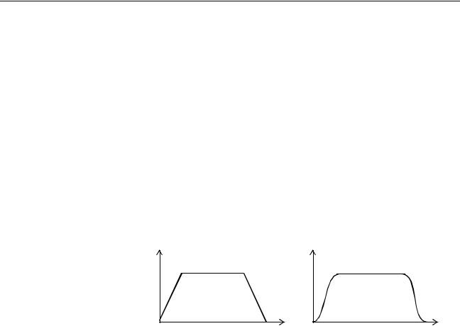
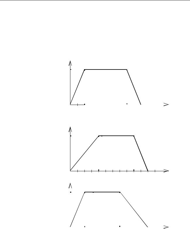
Reduced Machine Wear |
The traditional trapezoidal speed profile is provided to generate smooth start- |
|
ing and stopping. The trapezoidal corners can be rounded off to S-curves. |
Trapezoidal Speed Profile with |
Trapezoidal Speed Profile with |
Square Corners |
S-curve Corners |
Speed |
Speed |
Time |
Time |
4
System Configuration |
Section 1-2 |
1-2 |
System Configuration |
|
||
Basic Configuration |
|
|
|
|
W-series Servo Driver |
MCW151 |
Personal Computer running Motion Perfect |
||
|
||||
|
M CW15 1 |
|
Personal |
|
|
|
Computer |
||
|
SD |
RD |
|
|
|
RUN |
ST S |
|
|
|
|
PORT0 ,1 |
|
|
|
|
PORT2 |
1 |
Typical applicable Units for Serial Comm. Ports |
|
|
|
||
|
1 |
2 |
|
|
|
|
|
|
PC |
|
|
I/ O |
|
|
|
|
|
2 |
|
|
25 |
2 6 |
|
Programmable |
|
|
+ 24 V |
|
|
|
|
0V |
|
Terminal (PT) |
|
|
|
|
General-purpose |
|
|
|
|
device |
|
|
|
|
|
|
|
|
|
|
|
|
|
|
|
Typical applicable Actuators for Digital Outputs |
||||||||
Typical applicable Sensors for Servo |
|
|
|
|
|
|
|
|
|
|
|||||||||||||
Relais |
|
|
|
|
|
|
|
||||||||||||||||
Driver Digital Inputs |
|
|
|
|
|
|
|
|
|
|
|||||||||||||
|
|
|
|
|
|
|
|
||||||||||||||||
|
|
|
|
|
|
|
|
|
|
|
|
|
|
|
|
|
|
|
|
|
|
|
|
|
|
|
|
|
|
|
|
|
|
|
|
|
|
|
|
|
|
|
|
|
|
|
|
|
|
|
|
|
|
|
Print Registration |
|
|
|
|
|
|
|
|
|
|
|
|
|
|
|
|
|
|
|
|
|
|
|
|
|
|
|
|
|
|
|
|
|
|
|
|
|
|
||
|
|
|
|
|
|
|
|
|
|
|
|
|
Lamp |
|
|
|
|
|
|
|
|
||
|
|
|
|
|
|
|
|
|
|
|
|
|
|
|
|
|
|
|
|
|
|
|
|
|
|
|
|
|
|
|
|
|
|
|
|
|
|
|
|
|
|
|
|
|
|
|
|
|
|
|
|
|
|
|
|
|
|
|
|
|
|
|
|
|
|
|
|
|
|
|
|
|
|
|
|
|
|
|
|
|
|
|
|
|
|
|
|
|
|
|
|
|
|
|
|
|
|
|
|
|
|
|
|
|
|
|
|
|
|
|
|
|
|
|
|
|
|
|
|
|
|
|
|
|
|
|
Limit Switches |
|
|
|
|
|
|
Typical applicable Sensors for Digital Inputs |
|||||||||
|
|
|
|
|
|
|
|
|
|
|
|
|
|||||||||||
|
|
|
|
|
|
|
|
|
|
|
|
|
|||||||||||
|
|
|
|
|
|
|
|
|
|
|
|
|
|
|
|||||||||
|
|
|
|
|
|
|
|
|
|
|
|
|
|
|
|||||||||
Power Supply connection |
|
|
|
|
|
|
|
|
|
||||||||||||||
|
|
|
|
|
|
|
|
|
|||||||||||||||
Print Registration |
|
|
|
|
|
|
|
||||||||||||||||
|
|
|
|
|
|
|
|||||||||||||||||
|
|
|
|
|
|
|
|
|
|
|
|
|
|
|
|
|
|
|
|
|
|
||
|
|
|
|
|
|
|
|
|
|
|
|
|
|
|
|
|
|
|
|
|
|
|
|
24 V Power supply

 Proximity Sensor
Typical applicable Pulse Generators for
Encoder Input
Typical applicable Units for Encoder Output
MCW151 Unit
MCW151 Unit
Servo Driver
Note 1. The RS-422A/485 Serial Port 2 is only available on the MCW151-E Unit.
2.The MC Unit has one encoder axis. Either the encoder input or the encoder output can be used.
5
System Configuration |
|
|
|
|
|
|
|
|
|
Section 1-2 |
|
The equipment and models which can be used in the system configuration |
|||||||||
|
are shown in the following table. |
|
|
|
|
|
||||
|
|
|
|
|
|
|
|
|
|
|
|
Device |
|
|
|
|
Model |
|
|
||
|
|
|
|
|
|
|
|
|
|
|
|
Motion Control Unit |
R88A-MCW151-E |
|
|
|
|
|
|||
|
|
R88A-MCW151-DRT-E |
|
|
||||||
|
|
|
|
|
|
|
|
|
|
|
|
Servo Driver (see note) |
R88D-WT |
|
|
|
|
|
|||
|
|
|
|
|
|
|
|
|
|
|
|
Servomotor |
R88M-W |
|
|
|
|
|
|||
|
|
|
|
|
|
|
|
|
|
|
|
Control Devices (using |
Programmable Terminals |
|
|
||||||
|
Host Link) |
CPU Units |
|
|
|
|
|
|||
|
|
|
|
|
|
|
|
|
||
|
Personal Computer (for |
IBM Personal Computer or 100% compatible |
||||||||
|
Motion Perfect) |
|
|
|
|
|
|
|
|
|
|
|
|
|
|
|
|
|
|
|
|
|
Motion Perfect |
Version 2.0 or later |
|
|
|
|
|
|||
Note |
|
|
|
|
|
|
|
|
||
The MC Unit must be used with a Servo Driver with software version 14 or |
||||||||||
|
later. The MC Unit cannot be used with software version 8. |
|||||||||
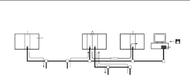
DeviceNet Configuration |
A DeviceNet system can be constructed in two ways: fixed allocation or free |
|||||||||
(MCW151-DRT-E only) |
allocation. |
|
|
|
|
|
|
|
|
|
|
Fixed Allocation |
|
|
|
|
|
|
|
|
|
|
A DeviceNet system can be constructed easily without the Configurator. With |
|||||||||
|
fixed allocation, predetermined words are allocated to each node for the |
|||||||||
|
Slave’s I/O. |
|
|
|
|
|
|
|
|
|
|
An OMRON Master must be used in order to perform fixed allocation. More- |
|||||||||
|
over, with fixed allocation only one Master Unit can be used in a DeviceNet |
|||||||||
|
network and only one Master Unit may be mounted to a PC. |
|||||||||
|
Master Unit |
|
|
|
|
|
|
|
|
|
|
|
|
CPU Unit |
|
|
|
|
|
||
|
|
|
Remote I/O communications |
|
|
|||||
|
|
|
|
|
|
|
|
|
|
|
|
|
|
Slave |
|
|
Slave |
|
|
MC Unit |
|
|
Free Allocation |
|
|
|
|
|
|
|
|
|
|
|
|
|
|
|
|
|
|
|
|
The Configurator can be used to freely allocate the words used by each Slave. With free allocation, more than one Master Unit can be connected in a DeviceNet network and each Master’s Slave I/O can be set independently. More than one Master Unit may be mounted to each PC and those Masters can be used independently. Furthermore, other companies’ Masters can be
6
Motion Control Concepts |
|
|
|
|
|
|
Section 1-3 |
|
|
|
used. For details, refer to the DeviceNet Configurator Operation Manual |
||||||
|
|
(W328). |
|
|
|
|
|
|
Master Unit |
|
|
Master Unit |
Master Unit |
||||
|
CPU Unit |
|
|
|
|
Configurator |
||
|
|
|
|
|
|
|||
|
|
|
|
|
|
|
|
ISA Board |
|
|
|
|
|
Message |
|
|
|
|
Remote I/O communications |
|
communications |
|||||
|
|
|
|
|
|
|
|
|
|
MC Unit |
|
Slave |
|
|
|
|
|
|
|
|
|
|
|
|
|
|
|
|
|
|
|
Slave |
|
MC Unit |
|
|
|
|
|
|
|
|
||
|
|
|
|
|
|
|
|
|
The following OMRON Master Units can be used.
Applicable PC |
Master Unit model |
Mounting position |
Max. number of Units |
|
|
number |
|
|
|
|
|
With |
Without |
|
|
|
|
||
|
|
|
Configurator |
Configurator |
|
|
|
|
|
CS1 Series |
CS1-DRM21 |
CPU Rack or Expansion I/O Rack |
16 |
1 |
|
|
(Classified as Special I/O Units) |
|
|
|
|
|
|
|
C200HZ/HX/HG/HE |
C200HW-DRM21-V1 |
CPU Rack or Expansion I/O Rack |
10 or 16 (see |
1 |
|
|
(Classified as Special I/O Units) |
note) |
|
|
|
|
|
|
Note Some CPUs can control 16 Master Units and other CPUs can control 10.
1-3 Motion Control Concepts
|
The MC Unit offers the following types positioning control operations. |
|
|
1. |
Point-to-point control |
|
2. |
Continuous Path control |
|
3. |
Electronic Gearing |
|
This section will introduce some of the commands and parameters as used in |
|
|
the BASIC programming of the motion control application. Refer to |
|
|
SECTION 6 BASIC Motion Control Programming Language for details. |
|
Coordinate System |
Positioning operations performed by the MC Unit are based on an axis coordi- |
|
|
nate system. The MC Unit converts the position data from either the con- |
|
|
nected Servo Driver or the connected encoder into an internal absolute |
|
|
coordinate system. |
|
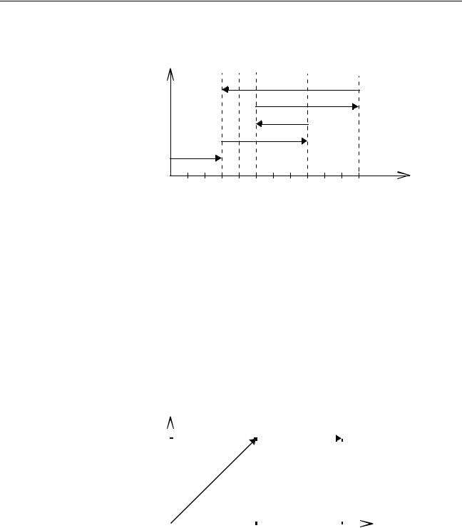
The engineering unit which specifies the distances of travelling can be freely defined for each axis separately. The conversion is performed through the use of the unit conversion factor, which is defined by the UNITS axis parameter. The origin point of the coordinate system can be determined using the DEFPOS command. This command re-defines the current position to zero or any other value.
A move is defined in either absolute or relative terms. An absolute move takes the axis to a specific predefined position with respect to the origin point. A relative move takes the axis from the current position to a position that is defined relative to this current position. The following diagram shows gives an exam-
7
Motion Control Concepts |
Section 1-3 |
ple of relative (command MOVE) and absolute (command MOVEABS) linear moves.
|
MOVEABS(30) |
|
|
|
MOVE(60) |
|
|
|
MOVEABS(50) |
|
|
|
MOVE(50) |
|
|
|
MOVE(30) |
|
|
0 |
50 |
100 |
Axis position |
|
|
|
1-3-1 PTP-control
In point-to-point positioning, each axis is moved independently of the other axis. The MC Unit supports the following operations.
•Relative move
•Absolute move
•Continuous move forward
•Continuous move reverse
Relative and Absolute Moves
To move a single axis either the command MOVE for a relative move or the command MOVEABS for an absolute move is used. Each axis has its own move characteristics, which are defined by the axis parameters.
Suppose a control program is executed to move from the origin to an axis no. 0 coordinate of 100 and axis no. 1 coordinate of 50. If the speed parameter is set to be the same for both axes and the acceleration and deceleration rate are set sufficiently high, the movements for axis 0 and axis 1 will be as illustrated below.
Axis 1 |
|
|
|
|
|
|
|
|
|
|
|
|
|
|
|
|
|
|
|
|
|
MOVEABS(100) AXIS(0) |
|||
50 |
|
|
|
|
|
|
|
|
|
|
|
|
|
|
|
|
|
|
|
|
|
MOVEABS(50) AXIS(1) |
|||
|
|
|
|
|
|
|
|
|
|
|
|
|
|
|
|
|
|
|
|
|
|
|
|
|
|
|
|
|
|
|
|
|
|
|
|
|
|
|
|
|
|
|
|
|
|
|
|
|
|
|
|
|
|
|
|
|
|
|
|
|
|
|
|
|
|
|
|
|
|
|
|
|
|
|
|
|
|
|
|
|
|
|
|
|
|
|
|
|
|
|
|
|
|
|
|
|
|
|
|
|
|
|
|
|
|
|
|
|
|
|
|
|
|
|
|
|
|
|
|
|
|
|
|
|
|
|
|
|
|
|
|
|
|
|
|
|
|
|
|
|
|
|
|
|
|
|
|
|
|
|
|
|
|
|
|
|
|
|
|
|
|
|
|
|
|
|
|
|
|
|
|
|
|
|
|
|
|
|
|
|
|
|
|
|
|
|
|
|
|
|
|
|
|
|
|
|
|
|
|
|
|
|
|
|
|
|
|
|
|
|
|
|
|
|
|
|
|
|
|
|
|
|
|
|
|
|
|
|
|
|
|
|
|
|
|
|
|
|
|
|
|
|
|
|
|
|
|
|
|
|
|
|
|
|
|
|
|
|
|
|
|
|
|
|
|
|
|
|
|
|
|
|
|
|
|
|
|
|
|
|
|
|
|
|
|
|
|
|
|
|
|
|
|
|
|
|
|
|
|
|
|
|
|
|
|
|
|
|
|
|
|
|
|
|
|
|
|
|
|
|
|
|
|
|
|
|
|
|
|
|
|
|
|
|
|
|
|
|
|
|
|
|
|
|
|
|
|
|
|
|
|
|
|
|
|
|
|
|
|
|
|
|
|
|
|
|
|
|
|
|
|
|
|
|
|
|
|
|
|
|
|
|
|
|
|
|
|
|
|
|
|
|
|
|
|
|
|
|
|
|
|
|
|
|
|
|
|
|
|
|
|
|
|
|
|
|
|
|
|
|
|
|
|
|
|
|
|
|
|
|
|
|
|
|
|
|
|
|
|
|
|
|
|
|
|
|
|
|
|
|
|
|
|
|
|
|
|
|
|
|
|
|
|
|
|
|
|
|
|
|
|
|
|
|
|
|
|
|
|
|
|
|
|
|
|
|
|
|
|
|
|
|
|
|
|
|
|
|
|
|
|
|
|
|
|
|
|
|
|
|
|
|
|
|
|
|
|
|
|
|
|
|
|
|
|
|
|
|
|
|
|
|
|
|
|
|
|
|
|
|
|
|
|
|
|
|
|
|
|
|
|
|
|
|
|
|
|
|
|
|
|
|
|
|
|
|
|
|
|
|
|
|
|
|
|
|
|
|
|
|
|
|
|
|
|
|
|
|
|
|
|
|
|
|
|
|
|
0 |
50 |
100 |
Axis 0 |
|
|
|
At start, both the axis 0 and axis 1 will move to a coordinate of 50 over the same duration of time. At this point, axis 1 will stop and the axis 0 will continue to move to a coordinate of 100.
Relevant Axis Parameters As mentioned before the move of a certain axis is determined by the axis parameters. Some relevant parameters are given in the next table.
Parameter |
Description |
|
|
UNITS |
Unit conversion factor |
|
|
ACCEL |
Acceleration rate of an axis in units/s2 |
DECEL |
Deceleration rate of an axis in units/s2 |
SPEED |
Demand speed of an axis in units/s |
|
|
8
Motion Control Concepts |
Section 1-3 |
Defining moves |
The speed profile below shows a simple MOVE operation. The UNITS param- |
|
eter for this axis has been defined for example as meters. The required maxi- |
|
mum speed has been set to 10 m/s. In order to reach this speed in one |
|
second and also to decelerate to zero speed again in one second, both the |
|
acceleration as the deceleration rate have been set to 10 m/s2. The total dis- |
|
tance travelled is the sum of distances travelled during the acceleration, con- |
|
stant speed and deceleration segments. Suppose the distance moved by the |
|
MOVE command is 40 m, the speed profile will be given by the following |
|
graph. |
Speed
|
|
|
|
|
|
|
|
|
|
|
|
ACCEL=10 |
10 |
|
|
|
|
|
|
|
|
|
|
|
DECEL=10 |
|
|
|
|
|
|
|
|
|
|
|
SPEED=10 |
|
|
|
|
|
|
|
|
|
|
|
|
|
|
|
|
|
|
|
|
|
|
|
|
|
|
|
|
|
|
|
|
|
|
|
|
|
|
|
|
|
|
|
|
|
|
|
|
|
|
|
|
MOVE(40) |
|
|
|
|
|
|
|
|
|
|
|
||
|
|
|
|
|
|
|
|
|
|
|
|
0 |
|
|
|
|
|
|
|
|
|
|
|
|
|
|
|
|
|
|
|
|
|
|
|
|
|
|
|
|
|
|
|
|
|
|
|
|
|
|
|
|
|
|
|
|
|
|
|
|
|
|
|
|
|
|
|
|
|
|
|
|
|
|
|
|
|
|
|
|
|
|
|
|
|
|
|
|
|
|
|
|
|
|
|
|
|
|
|
|
|
|
|
|
|
|
|
|
|
|
|
|
|
|
|
|
|
|
|
|
|
|
|
|
|
|
|
|
|
|
|
|
|
|
|
|
|
|
|
|
|
|
|
|
|
|
|
|
|
|
|
|
|
|
|
|
|
|
|
|
|
|
|
|
|
|
|
|
|
|
|
|
|
|
|
|
|
|
|
|
|
|
|
|
|
|
|
|
|
|
|
|
|
|
|
|
|
|
|
|
|
|
|
|
|
|
|
|
|
|
|
|
|
|
|
|
|
|
|
|
|
|
|
|
|
|
|
|
|
|
|
|
|
|
|
|
|
|
|
|
|
|
|
|
|
|
|
|
|
|
|
|
|
|
|
|
|
|
|
|
|
|
|
|
|
|
|
|
|
|
|
|
|
|
|
|
|
|
|
|
|
|
|
|
|
|
|
|
|
|
|
|
|
|
|
|
|
|
|
|
|
|
|
|
|
|
|
|
|
|
|
|
|
|
|
|
|
|
|
|
|
|
|
|
|
|
|
|
|
|
|
|
|
|
|
|
|
|
|
|
|
|
|
|
|
|
|
1 |
2 |
3 |
4 |
5 |
6 |
Time |
|||||||||||||||||
The following two speed profiles show the same movement with an acceleration time respectively a deceleration time of 2 seconds.
Speed
|
|
|
|
|
|
|
|
|
|
|
|
|
|
|
|
|
|
|
|
ACCEL=5 |
10 |
|
|
|
|
|
|
|
|
|
|
|
|
|
|
|
|
|
|
|
DECEL=10 |
|
|
|
|
|
|
|
|
|
|
|
|
|
|
|
|
|
|
|
SPEED=10 |
|
|
|
|
|
|
|
|
|
|
|
|
|
|
|
|
|
|
|
|
|
|
|
|
|
|
|
|
|
|
|
|
|
|
|
|
|
|
|
|
|
|
|
|
|
|
|
|
|
|
|
|
|
|
|
|
|
|
|
|
|
|
|
|
|
|
|
|
|
|
|
|
|
|
|
|
|
|
|
|
|
|
|
|
MOVE(40) |
|
|
|
|
|
|
|
|
|
|
|
|
|
|
|
|
|
|
|
|
|
|
|
|
|
|
|
|
|
|
|
|
|
|
|
|
|
|
|
|
0 |
|
|
|
|
|
|
|
|
|
|
|
|
|
|
|
|
|
|
|
|
|
|
|
|
|
|
|
|
|
|
|
|
|
|
|
|
|
|
|
|
|
|
|
|
|
|
|
|
|
|
|
|
|
|
|
|
|
|
|
|
|
|
|
|
|
|
|
|
|
|
|
|
|
|
|
|
|
|
|
|
|
|
|
|
|
|
|
|
|
|
|
|
|
|
|
|
|
|
|
|
|
|
|
|
|
|
|
|
|
|
|
|
|
|
|
|
|
|
|
|
|
|
|
|
|
|
|
|
|
|
|
|
|
|
|
|
|
|
|
|
|
|
|
|
|
|
|
|
|
|
|
|
|
|
|
|
|
|
|
|
|
|
|
|
|
|
|
|
|
|
|
|
|
|
|
|
|
|
|
|
|
|
|
|
|
|
|
|
|
|
|
|
|
|
|
|
|
|
|
|
|
|
|
|
|
|
|
|
|
|
|
|
|
|
|
|
|
|
|
|
|
|
|
|
|
|
|
|
|
|
|
|
|
|
|
|
|
|
|
|
|
|
|
|
|
|
|
|
|
|
|
|
|
|
|
|
|
|
|
|
|
|
|
|
|
|
|
|
|
|
|
|
|
|
|
|
|
|
|
|
|
|
|
|
|
|
|
|
|
|
|
|
|
|
|
|
|
|
|
|
|
|
|
|
|
|
|
|
|
|
|
|
|
|
|
|
|
|
|
|
|
|
|
|
|
|
|
|
|
|
|
|
|
|
|
|
|
|
|
|
|
|
|
|
|
|
|
|
|
|
|
|
|
|
|
|
|
|
|
|
|
|
|
|
|
|
|
|
|
|
|
|
|
|
|
|
|
|
|
|
|
|
|
|
|
|
|
|
|
|
|
|
|
|
|
|
|
|
|
|
|
|
|
|
|
|
|
|
|
|
|
|
|
|
|
|
|
|
|
|
|
|
|
|
|
|
|
|
|
|
|
|
|
|
|
|
|
|
|
|
|
|
|
|
|
|
|
|
|
|
|
|
|
|
|
|
|
|
|
|
|
|
|
|
|
|
|
|
|
|
|
|
|
|
|
|
|
|
|
|
|
|
|
|
|
|
|
|
|
|
|
|
|
|
|
|
|
|
|
|
|
|
|
|
|
|
|
|
|
|
|
|
|
|
|
|
|
|
|
|
|
|
|
|
|
|
|
|
|
|
|
|
|
|
|
|
|
|
|
|
|
|
|
|
|
|
|
|
|
|
|
|
|
|
1 |
|
|
|
|
2 |
3 |
4 |
5 |
6 |
Time |
||||||||||||||||||||||||||
Speed |
|
|
|
|
|
|
|
|
|
|
|
|
|
|
|
|
|
|
|
|
|
|
|
|
|
|
|
|
|
|
|
|
|
|
|
|
|
|
|
|
|
|
|
|
|
|
|
|
|
|
|
|
|
|
|
|
|
|
|
|
|
|
|
|
|
|
|
|
|
|
|
ACCEL=10 |
|
10 |
|
|
|
|
|
|
|
|
|
|
|
|
|
|
|
|
|
|
|
|
|
|
|
|
|
|
|
|
|
|
|
|
|
|
DECEL=5 |
|
|
|
|
|
|
|
|
|
|
|
|
|
|
|
|
|
|
|
|
|
|
|
|
|
|
|
|
|
|
|
|
|
|
|
SPEED=10 |
||
|
|
|
|
|
|
|
|
|
|
|
|
|
|
|
|
|
|
|
|
|
|
|
|
|
|
|
|
|
|
|
|
|
|
|
||
|
|
|
|
|
|
|
|
|
|
|
|
|
|
|
|
|
|
|
|
|
|
|
|
|
|
|
|
|
|
|
|
|
|
|
||
|
|
|
|
|
|
|
|
|
|
|
|
|
|
|
|
|
|
|
|
|
|
|
|
|
|
|
|
|
|
|
|
|
|
|
||
|
|
|
|
|
|
|
|
|
|
|
|
|
|
|
|
|
|
|
|
|
|
|
|
|
|
|
|
|
|
|
|
|
|
|
MOVE(40) |
|
|
|
|
|
|
|
|
|
|
|
|
|
|
|
|
|
|
|
|
|
|
|
|
|
|
|
|
|
|
|
|
|
|
|
|
||
|
|
|
|
|
|
|
|
|
|
|
|
|
|
|
|
|
|
|
|
|
|
|
|
|
|
|
|
|
|
|
|
|
|
|
||
|
|
|
|
|
|
|
|
|
|
|
|
|
|
|
|
|
|
|
|
|
|
|
|
|
|
|
|
|
|
|
|
|
|
|
|
|
|
|
|
|
|
|
|
|
|
|
|
|
|
|
|
|
|
|
|
|
|
|
|
|
|
|
|
|
|
|
|
|
|
|
|
|
|
|
|
|
|
|
|
|
|
|
|
|
|
|
|
|
|
|
|
|
|
|
|
|
|
|
|
|
|
|
|
|
|
|
|
|
|
|
|
|
|
|
|
|
|
|
|
|
|
|
|
|
|
|
|
|
|
|
|
|
|
|
|
|
|
|
|
|
|
|
|
|
|
|
|
|
|
|
|
|
|
|
|
|
|
|
|
|
|
|
|
|
|
|
|
|
|
|
|
|
|
|
|
|
|
|
|
|
|
|
|
|
|
|
|
|
|
|
|
|
|
|
|
|
|
|
|
|
|
|
|
|
|
|
|
|
|
|
|
|
|
|
|
|
|
|
|
|
|
|
|
|
|
|
|
|
|
|
|
|
|
|
|
|
|
|
|
|
|
|
|
|
|
|
|
|
|
|
|
|
|
|
|
|
|
|
|
|
|
|
|
|
|
|
|
|
|
|
|
|
|
|
|
|
|
|
|
|
|
|
|
|
|
|
|
|
|
|
|
|
|
|
|
|
|
|
|
|
|
|
|
|
|
|
|
|
|
|
|
|
|
|
|
|
|
|
|
|
|
|
|
|
|
|
|
|
|
|
|
|
|
|
|
|
|
|
|
|
|
|
|
|
|
|
|
|
|
|
|
|
|
|
|
|
|
|
|
|
|
|
|
|
|
|
|
|
|
|
|
|
|
|
|
|
|
|
|
|
|
|
|
|
|
|
|
|
|
|
|
|
|
|
|
|
|
|
|
|
|
|
|
|
|
|
|
|
|
|
|
|
|
|
|
|
|
|
|
|
|
|
|
|
|
|
|
|
|
|
|
|
|
|
|
|
|
|
|
|
|
|
|
|
|
|
|
|
|
|
|
|
|
|
|
|
|
|
|
|
|
|
|
|
|
|
|
|
|
|
|
|
|
|
|
|
|
|
|
|
|
|
|
|
|
|
|
|
|
|
|
|
|
|
|
|
|
|
|
|
|
|
|
|
|
|
|
|
|
|
|
|
|
|
|
|
|
|
|
|
|
|
|
|
|
|
|
|
|
|
|
|
|
|
|
|
|
|
|
|
|
|
|
|
|
|
|
|
|
|
|
|
|
|
|
|
|
|
|
|
|
|
|
|
|
|
|
|
|
|
|
|
|
|
|
|
|
|
|
|
|
|
|
|
|
|
|
|
|
|
|
|
0 |
1 |
2 |
3 |
4 |
5 |
6 |
Time |
Move Calculations |
The following equations are used to calculate the total time for the motion of |
|||||||
|
the axes. Consider the moved distance for the MOVE command as D, the |
|||||||
|
demand speed as V , the acceleration rate a and deceleration rate d . |
|||||||
9

Motion Control Concepts |
Section 1-3 |
Continuous Moves
1-3-2 CP-control
Linear Interpolation
Acceleration time
Acceleration distance
Deceleration time
Deceleration distance
Constant speed distance
Total time
V
= -- a
V2
= -----
2a
V
= -- d
V2
= -----
2d
V2 ( a + d)
= D – -----------------------
2ad
DV( a + d)
=--- + --------------------
V 2ad
The FORWARD and REVERSE commands can be used to start a continuous movement with constant speed on a certain axis. The FORWARD command will move the axis in positive direction and the REVERSE command in negative direction. For these commands also the axis parameters ACCEL and SPEED apply to specify the acceleration rate and demand speed.
Both movements can be canceled by using either the CANCEL or RAPIDSTOP command. The CANCEL command will cancel the move for one axis and RAPIDSTOP will cancel moves on all axes. The deceleration rate is set by DECEL.
Continuous Path control enables to control a specified path between the start and end position of a movement for one or multiple axes. The MC Unit supports the following operations.
•Linear interpolation
•Circular interpolation
•CAM control
In applications it can be required for a set of motors to perform a move operation from one position to another in a straight line. Linearly interpolated moves can take place among several axes. The commands MOVE and MOVEABS are also used for the linear interpolation. In this case the commands will have multiple arguments to specify the relative or absolute move for each axis. Consider the following three axis move in a 3-dimensional plane.
MOVE(50,50,50)
Axis 2 |
Speed |
Axis 1 |
Time
Axis 0
10
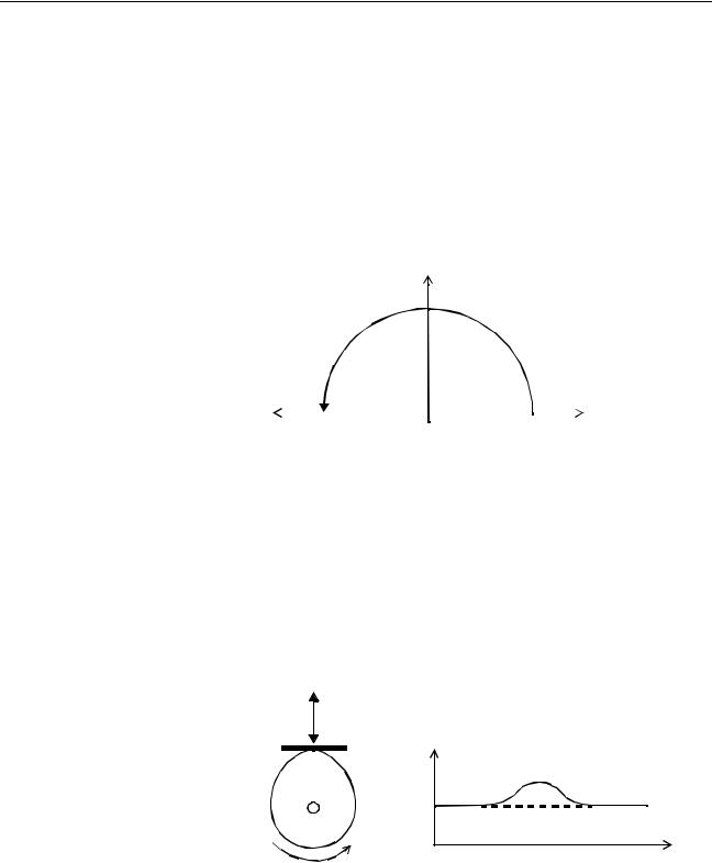
Motion Control Concepts |
Section 1-3 |
The speed profile of the motion along the path is given in the diagram. The three parameters SPEED, ACCEL and DECEL which determine the multi axis movement are taken from the corresponding parameters of the base axis. The MOVE command computes the various components of speed demand per axis.
Circular Interpolation
It may be required that a tool travels from the starting point to the end point in an arc of a circle. In this instance the motion of two axes is related via a circular interpolated move using the MOVECIRC command. Consider the following diagram.
MOVECIRC(-100,0,-50,0,0)
Axis 1
50
|
|
|
Axis 0 |
|
-50 |
0 |
50 |
||
|
The centre point and desired end point of the trajectory relative to the start point and the direction of movement are specified. The MOVECIRC command computes the radius and the angle of rotation. Like the linearly interpolated MOVE command, the ACCEL, DECEL and SPEED variables associated with the base axis determine the speed profile along the circular move.
CAM Control
Additional to the standard move profiles the MC Unit also provides a way to define a position profile for the axis to move. The CAM command will move an axis according to position values stored in the MC Unit Table array. The speed of travelling through the profile is determined by the axis parameters of the axis.
CAM(0,99,100,20)
Position |
Time |
1-3-3 EG-Control
Electronic Gearing control allows you to create a direct gearbox link or a linked move between two axes. The MC Unit supports the following operations.
1.Electronic gearbox
2.Linked CAM
3.Linked move
4.Adding axes
11
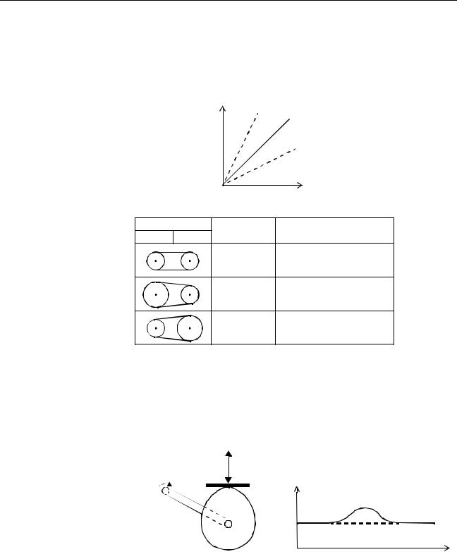
Motion Control Concepts |
Section 1-3 |
Electronic Gearbox
Linked CAM control
Linked Move
The MC Unit is able to have a gearbox link from one axis to another as if there is a physical gearbox connecting them. This can be done using the CONNECT command in the program. In the command the ratio and the axis to link to are specified.
CONNECT Axis
2:1 |
1:1 |
1:2 |
Master Axis
Axes |
Ratio |
CONNECT command |
0 |
1 |
|
|
1:1 |
CONNECT(1,0) AXIS(1) |
|
2:1 |
CONNECT(2,0) AXIS(1) |
|
1:2 |
CONNECT(0.5,0) AXIS(1) |
Next to the standard CAM profiling tool the MC Unit also provides a tool to link the CAM profile to another axis. The command to create the link is called CAMBOX. The travelling speed through the profile is not determined by the axis parameters of the axis but by the position of the linked axis. This is like connecting two axes through a cam.
CAMBOX(0,99,100,20,0) AXIS(1)
CAMBOX Axis (1) Position
Master Axis (0) Position
The MOVELINK command provides a way to link a specified move to a master axis. The move is divided into an acceleration, deceleration and constant
12
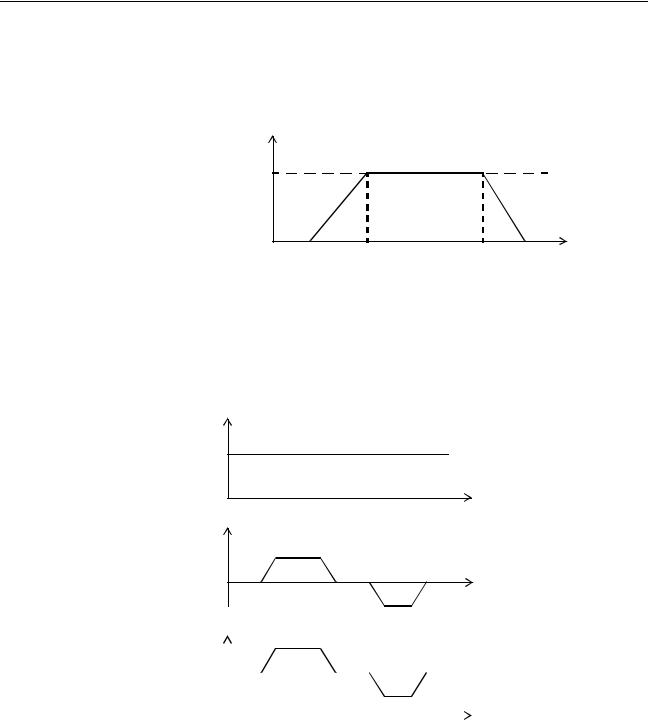
Motion Control Concepts |
Section 1-3 |
speed part and they are specified in master link distances. This can be particularly useful for synchronizing two axes for a fixed period.
MOVELINK(50,60,10,10,1) AXIS(0) |
Speed |
Master Axis (1) |
Synchronized |
MOVELINK Axis (0) |
Time
Adding Axes
It is very useful to be able to add all movements of one axis to another. One possible application is for instance changing the offset between two axes linked by an electronic gearbox. The MC Unit provides this possibility by using the ADDAX command. The movements of the linked axis will consists of all movements of the actual axis plus the additional movements of the master axis.
BASE(0)
Speed axis 0*
ADDAX(2)
FORWARD
MOVE(100) AXIS(2)
MOVE(-60) AXIS(2)
Speed axis 2 |
+ |
Time |
|
||
|
|
Speed axis 0 |
= |
|
|
|
|
|
|
|
|
|
|
|
Time |
|||||||||||||||
|
|
|
|
|
|
|
|
|
|
|
|
|
|
|
|
|
|
|
|
|
|
|
|
|
||||
|
|
|
|
|
|
|
|
|
|
|
|
|
|
|
|
|
|
|
|
|
|
|
|
|
|
|
||
|
|
|
|
|
|
|
|
|
|
|
|
|
|
|
|
|
|
|
|
|
|
|
|
|
|
|
|
|
|
|
|
|
|
|
|
|
|
|
|
|
|
|
|
|
|
|
|
|
|
|
|
|
|
|
|
|
|
|
|
|
|
|
|
|
|
|
|
|
|
|
|
|
|
|
|
|
|
|
|
|
|
|
|
|
|
|
|
Time |
1-3-4 Other Operations |
|
Canceling Moves |
In normal operation or in case of emergency it can be necessary to cancel the |
|
current movement from the buffers. When the CANCEL or RAPIDSTOP com- |
|
mands are given, the selected axis respectively all axes will cancel their cur- |
|
rent move. |
Origin Search |
The encoder feedback for controlling the position of the motor is incremental. |
|
This means that all movement must be defined with respect to an origin point. |
|
The DATUM command is used to set up a procedure whereby the MC Unit |
goes through a sequence and searches for the origin based on digital inputs and/or Z-marker from the encoder signal.
13
Control System Configuration |
|
Section 1-4 |
||
Print Registration |
The MC Unit can capture the position of an axis in a register when an event |
|||
|
occurs. The event is referred to as the print registration input. On the rising or |
|||
|
falling edge of an input signal, which is either the Z-marker or an input, the MC |
|||
|
Unit captures the position of an axis in hardware. This position can then be |
|||
|
used to correct possible error between the actual position and the desired |
|||
|
position. The print registration is set up by using the REGIST command. |
|||
|
The position is captured in hardware, and therefore there is no software over- |
|||
|
head and no interrupt service routines, eliminating the need to deal with the |
|||
|
associated timing issues. |
|
|
|
Merging Moves |
If the MERGE axis parameter is set to 1, a movement will always be followed |
|||
|
by a subsequent movement without stopping. The following illustrations will |
|||
|
show the transitions of two moves with MERGE value 0 and value 1. |
|||
|
Speed |
|
|
|
|
|
|
MERGE=0 |
|
|
|
|
||
|
|
|
|
|
|
|
|
Time |
|
|
Speed |
|
|
|
|
|
|
MERGE=1 |
|
|
|
|
||
|
|
|
|
|
|
|
|
Time |
|
Jogging |
Jogging moves the axes at a constant speed forward or reverse by manual |
|||
|
operation of the digital inputs. Different speeds are also selectable by input. |
|||
|
Refer to the FWD_JOG, REV_JOG and FAST_JOG axis parameters. |
|||
1-4 Control System Configuration
1-4-1 Servo System Principles
The servo system used by and the internal operation of the MC Unit are briefly described in this section. Refer to 2-4 Servo System Precautions for precautions related to servo system operation.
Semi-closed Loop System The servo system of the MC Unit uses a semi-closed or inferred closed loop system. This system detects actual machine movements by the rotation of the motor in relation to a target value. It calculates the error between the target value and actual movement, and reduces the error through feedback.
14
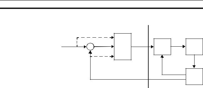
Control System Configuration |
|
|
Section 1-4 |
|
|
MC Unit |
Servo System |
|
|
|
|
2 |
|
|
|
|
|
3 |
|
Demand |
|
1 |
Speed |
|
position |
+ |
reference |
|
|
|
|
Position |
Speed |
Motor |
|
|
Control |
Control |
|
|
|
|
||
|
|
- |
|
|
|
|
|
|
4 |
|
|
|
Measured |
|
|
|
|
speed |
|
|
|
|
|
Encoder |
|
|
Measured |
|
|
|
|
position |
|
|
Internal Operation of the Inferred closed loop systems occupy the mainstream in modern servo sys- MC Unit tems applied to positioning devices for industrial applications. The following graph shows the basic principle of the Servo System as used in the MC Unit.
1,2,3... 1. The MC Unit performs actual position control. The main input of the controller is the following error, which is the calculated difference between the demand position and the actual measured position.
2.The Position Controller calculates the required speed reference output determined by the following error and possibly the demanded position and the measured position. The speed reference is provided to the Servo Driver.
3.The Servo Driver controls the rotational speed of the Servomotor corresponding to the speed reference. The rotational speed is proportional to the speed reference.
4.The rotary encoder will generate the feedback pulses for both the speed feedback within the Servo Driver speed loop and the position feedback within the MC Unit position loop.
Motion Control Algorithm The servo system controls the motor by continuously adjusting the speed reference to the Servo Driver. The speed reference is calculated by the MC Unit’s Motion Control algorithm, which is explained in this section.
The Motion Control algorithm uses the demand position, the measured position and the following error to determine the speed reference. The following error is the difference between the demanded and measured position. The demand position, measured position and following error are represented by axis parameters MPOS, DPOS and FE. Five gain values have been implemented for the user to be able to configure the correct control operation for each application.
15
Loading...