


 Loading...
Manual No.
8U0108-E1-01
XtraDrive (XD-) SERIES
AC Servo Driver
USER’S Manual
Copyright 2003 by YET, Yaskawa Eshed Technology Ltd.
XtraDrive User Manual
Catalog No.8U0108, Revision C
November 2003
All rights reserved. No part of this publication may be stored in a retrieval system, or reproduced in any way, including but not limited to photocopy, photography, magnetic or other recording, without the prior agreement and written permission of the publisher. Program listings may be entered, stored and executed in a computer system, but not reproduced for publication.
This guide is designed to provide information about the XtraDrive hardware. Every effort has been made to make this guide complete and as accurate as possible. However, no warranty of suitability, purpose or fitness is made or implied. YET Ltd. is not liable or responsible to any person or entity for loss or damage in connection with or stemming from the use of XtraDrive and/or the information contained in this publication
YET Ltd. bears no responsibility for errors, which may appear in this publication and retains the right to make changes to the products and the guide without prior notice.
YET Ltd. ISRAEL |
YET US Inc. |
13 Hamelacha St., |
531 King St., |
Afeq Industrial Estate |
Unit 1 |
Rosh Ha’ayin 48091 |
Littleton, MA 01460 |
ISRAEL |
USA |
Tel: +972-3-9004114 |
Tel: +1-866-YET-8080 |
Fax: +972-3-9030412 |
Fax: +1-978-952-6821 |
info@yetmotion.com |
USinfo@yetmotion.com |
|
|
web site: www.yetmotion.com |
|
ii

 WARNING
YET manufactures component parts that can be used in a wide variety of industrial applications. The selection and application of YET products remain the responsibility of the equipment designer or end user. YET accepts no responsibility for the way its products are incorporated into the final system design.
Under no circumstances should any YET product be incorporated into any product or design as the exclusive or sole safety control. Without exception, all controls should be designed to detect faults dynamically and fail safely under all circumstances. All products designed to incorporate a component part manufactured by YET must be supplied to the end user with appropriate warnings and instructions as to that part’s safe use and operation. Any warnings provided by YET must be promptly provided to the end user.
YET offers an express warranty only as to the quality of its products in conforming to standards and specifications published in YET’s manual. NO OTHER WARRANTY, EXPRESS OR IMPLIED, IS OFFERED. YET assumes no liability for any personal injury, property damage, losses, or claims arising from misapplication of its products.
iii
This page intentionally left blank.
iv

Safety Information
The following defines the symbols used in this manual to indicate varying degrees of safety precautions and to identify the corresponding level of hazard inherent to each. Failure to follow precautions provided in this manual can result in serious, possibly even fatal, injury, and/or damage to the persons, products, or related equipment and systems.
 WARNING
•WARNING: Indicates a potentially hazardous situation, which, if not heeded, could result in death or serious injury.
 CAUTION
•CAUTION: Indicates a potentially hazardous situation, which, if not avoided, may result in minor or moderate injury.
v
This page intentionally left blank.
vi
XtraDrive User Manual |
Table of Contents/Preface |
Table of Contents
1. Checking Product and Part Names................................................................. |
1-1 |
|
1.1. Checking the XtraDrive Series Products on Delivery................................... |
1-2 |
|
1.1.1. |
Servo Amplifiers....................................................................................... |
1-2 |
1.2. Product Part Names........................................................................................ |
1-3 |
|
1.2.1. |
Servo Amplifiers....................................................................................... |
1-3 |
1.2.2. |
Model Numbers ........................................................................................ |
1-4 |
2.Installation.............................................................................…………………2-1
|
2.1. |
Servo Amplifiers ............................................................................................ |
2-2 |
|
|
2.1.1. |
Storage Conditions.................................................................................... |
2-2 |
|
|
2.1.2. |
Installation Site ......................................................................................... |
2-2 |
|
|
2.1.3. |
Orientation................................................................................................. |
2-3 |
|
|
2.1.4. |
Installation................................................................................................. |
2-3 |
|
3. |
Wiring…… ........................................................................................................ |
3-1 |
||
|
3.1. |
Connecting to Peripheral Devices.................................................................. |
3-2 |
|
|
3.1.1. |
Single-Phase 200V Main Circuit Specifications ..................................... |
3-3 |
|
|
3.1.2. |
Single-Phase 0.8kW 200V Main Circuit Specifications ......................... |
3-4 |
|
|
3.1.3. |
Three-phase 200V Main Circuit Specifications....................................... |
3-5 |
|
|
3.1.4. |
Three-Phase 400V Main Circuit Specifications ...................................... |
3-6 |
|
|
3.2. |
XtraDrive Internal Block Diagrams............................................................... |
3-7 |
|
|
3.2.1. |
Single-phase 30W to 800W, 200V Models ............................................. |
3-7 |
|
|
3.2.2. |
Three-phase 1kW to 3kW, 200V Models ................................................ |
3-8 |
|
|
3.2.3. |
Three-phase 0.5kW to 3.0kW, 400V Models.......................................... |
3-9 |
|
|
3.3. |
Main Circuit Wiring ..................................................................................... |
3-10 |
|
|
3.3.1. |
Names and Descriptions of Main Circuit Terminal............................... |
3-11 |
|
|
3.3.2. |
Typical Main Circuit Wiring Example .................................................. |
3-12 |
|
|
3.3.3. |
Servo Amplifier Power Losses............................................................... |
3-13 |
|
|
3.3.4. |
Wiring Main Circuit Terminal Blocks................................................... |
3-14 |
|
|
3.4. |
I/O Signals .................................................................................................... |
3-15 |
|
|
3.4.1. |
Example of Typical I/O Signal Connections ......................................... |
3-15 |
|
|
3.4.2. |
List of CN1 Terminals............................................................................ |
3-16 |
|
|
3.4.3. |
I/O Signal Names and Functions............................................................ |
3-17 |
|
|
3.4.4. |
Interface Circuits..................................................................................... |
3-19 |
|
|
3.5. |
Wiring Encoders (for SGMGH and SGMSH Motors Only) ...................... |
3-23 |
|
|
3.5.1. |
Encoder Connections.............................................................................. |
3-23 |
|
|
3.5.2. |
CN2 Encoder Connector Terminal Layout and Types.......................... |
3-25 |
|
|
3.5.3. |
Encoder Cables Interconnections........................................................... |
3-26 |
|
|
3.6. |
Examples of Standard Connections ............................................................. |
3-28 |
|
4. |
Trial Operation ................................................................................................. |
4-1 |
||
|
4.1. |
Two-Step Trial Operation .............................................................................. |
4-2 |
|
|
4.1.1. |
Step 1: Trial Operation for Servomotor without Load ............................ |
4-3 |
|
|
4.1.2. |
Step 2: Trial Operation with Servomotor Connected to Machine........... |
4-9 |
|
|
4.2. |
Additional Setup Procedures in Trial Operation ......................................... |
4-10 |
|
|
4.2.1. |
Servomotors with Brakes ....................................................................... |
4-10 |
|
|
4.2.2. |
Position Control by Host Controller....................................................... |
4-11 |
|
|
4.3. |
Minimum Parameters and Input Signals ..................................................... |
4-12 |
|
|
4.3.1. |
Parameters............................................................................................... |
4-12 |
|
|
4.3.2. |
Input Signals ........................................................................................... |
4-12 |
|
vii
XtraDrive User Manual |
Table of Contents/Preface |
5. Parameter Settings and Functions .................................................................. |
5-1 |
||
5.1. |
Settings According to Device Characteristics ............................................... |
5-4 |
|
5.1.1. |
Switching Servomotor Rotation Direction............................................... |
5-4 |
|
5.1.2. |
Setting the Overtravel Limit Function ..................................................... |
5-5 |
|
5.1.3. |
Limiting Torque........................................................................................ |
5-8 |
|
5.2. |
Settings According to Host Controller......................................................... |
5-12 |
|
5.2.1. |
Speed Reference ..................................................................................... |
5-12 |
|
5.2.2. |
Position Reference .................................................................................. |
5-14 |
|
5.2.3. |
Using the Encoder Signal Output........................................................... |
5-20 |
|
5.2.4. |
Sequence I/O Signals.............................................................................. |
5-23 |
|
5.2.5. |
Using the Electronic Gear Function....................................................... |
5-25 |
|
5.2.6. |
Contact Input Speed Control .................................................................. |
5-29 |
|
5.2.7. |
Using Torque Control............................................................................. |
5-34 |
|
5.2.8. |
Torque Feed-Forward Function ............................................................. |
5-40 |
|
5.2.9. |
Torque Limiting by Analog Voltage Reference .................................... |
5-42 |
|
5.2.10. |
Reference Pulse Inhibit Function (/INHIBIT) ....................................... |
5-44 |
|
5.3. |
Setting Up the Servo Amplifier ................................................................... |
5-45 |
|
5.3.1. |
Parameters............................................................................................... |
5-45 |
|
5.3.2. |
JOG Speed .............................................................................................. |
5-46 |
|
5.3.3. |
Input Circuit Signal Allocation .............................................................. |
5-46 |
|
5.3.4. |
Output Circuit Signal Allocation............................................................ |
5-50 |
|
5.3.5. |
Control Mode Selection.......................................................................... |
5-52 |
|
5.4. |
Setting Stop Functions ................................................................................. |
5-54 |
|
5.4.1. |
Adjusting Offset...................................................................................... |
5-54 |
|
5.4.2. |
Servo OFF Stop Mode Selection............................................................ |
5-55 |
|
5.4.3. |
Using the Zero Clamp Function............................................................. |
5-56 |
|
5.4.4. |
Using the Holding Brake........................................................................ |
5-58 |
|
5.5. |
Forming a Protective Sequence ................................................................... |
5-61 |
|
5.5.1. |
Using Servo Alarm and Alarm Code Outputs ....................................... |
5-61 |
|
5.5.2. |
Using the Servo ON Input Signal (/S-ON) ............................................ |
5-63 |
|
5.5.3. |
Using the Positioning Completed Output Signal (/COIN).................... |
5-64 |
|
5.5.4. |
Speed Coincidence Output (/V-CMP) ................................................... |
5-65 |
|
5.5.5. |
Using the Running Output Signal (/TGON).......................................... |
5-67 |
|
5.5.6. |
Using the Servo Ready Output Signal (/S-RDY) .................................. |
5-68 |
|
5.5.7. |
Using the Warning Output Signal (/WARN)......................................... |
5-69 |
|
5.5.8. |
Handling Power Loss.............................................................................. |
5-71 |
|
5.6. |
Selecting a Regenerative Resistor................................................................ |
5-72 |
|
5.6.1. |
External Regenerative Resistor .............................................................. |
5-73 |
|
5.6.2. |
Calculating the Regenerative Power Capacity....................................... |
5-74 |
|
5.7. |
Absolute Encoders........................................................................................ |
5-78 |
|
5.7.1. |
Interface Circuit ...................................................................................... |
5-79 |
|
5.7.2. |
Configuring an Absolute Encoder.......................................................... |
5-80 |
|
5.7.3. |
Absolute Encoder Setup ......................................................................... |
5-81 |
|
5.7.4. |
Absolute Encoder Reception Sequence ................................................. |
5-84 |
|
5.8. |
AB Encoders................................................................................................. |
5-89 |
|
5.9. |
Configuration of Serial Commands for AB Encoders ................................ |
5-91 |
|
5.9.1. |
Position Control ...................................................................................... |
5-91 |
|
5.9.1.1. |
Defining User Units for Motion Profiles ............................................... |
5-91 |
|
5.9.1.2. |
Position Units.......................................................................................... |
5-91 |
|
5.9.1.3. |
Speed Units ............................................................................................. |
5-92 |
|
viii
XtraDrive User Manual |
Table of Contents/Preface |
5.9.1.4. |
Acceleration Units .................................................................................. |
5-93 |
5.9.1.5. |
Setting Default Motion Profile Parameters............................................ |
5-94 |
5.9.1.6. |
Profile Speed (Pn2A2, Pn2A3) .............................................................. |
5-95 |
5.9.1.7. |
Profile Acceleration (Pn2A4, Pn2A5).................................................... |
5-95 |
5.9.1.8. |
Jerk Smoothing Time (Pn2A6) .............................................................. |
5-95 |
5.9.1.9. |
Quick Stop Deceleration (Pn2A8, Pn2A9)............................................ |
5-96 |
5.9.1.10. |
Motion End Window (Pn2C0) ............................................................... |
5-96 |
5.9.2. |
Torque Control........................................................................................ |
5-96 |
5.9.2.1. |
Torque Slope (Pn2C1) .............................................................. |
5-96 |
5.9.3. |
Homing.................................................................................................... |
5-97 |
5.9.4. |
Digital I/O ............................................................................................... |
5-98 |
5.9.5. |
Auto Tuning............................................................................................ |
5-99 |
5.10. Auto Running a User Program..................................................................... |
5-99 |
||
6. Servo Adjustment.............................................................................................. |
6-1 |
||
6.1. |
Selection of Control Mode............................................................................. |
6-2 |
|
6.2. |
Analog Input or Contact Input Velocity Control........................................... |
6-3 |
|
6.2.1. |
Principle and Block Diagram of the Velocity Control ............................ |
6-3 |
|
6.2.2. |
Parameters of the Velocity Control.......................................................... |
6-4 |
|
6.2.3. |
Setting the Input Gain............................................................................... |
6-4 |
|
6.2.4. |
Adjusting Offset........................................................................................ |
6-5 |
|
6.2.5. |
Using the Soft Start Function ................................................................... |
6-6 |
|
6.2.6. |
Load Inertia Setting................................................................................... |
6-7 |
|
6.2.7. |
Adjusting Speed Loop Gain ..................................................................... |
6-8 |
|
6.2.8. |
Setting the Torque Reference Filter Time Constant ................................ |
6-9 |
|
6.2.9. |
Notch Filter ............................................................................................... |
6-9 |
|
6.2.10. |
Gain Setting Reference Values............................................................... |
6-10 |
|
6.3. |
NCT Position Control................................................................................... |
6-12 |
|
6.3.1. |
Load Inertia Setting................................................................................. |
6-12 |
|
6.3.2. |
Position Control Block Diagram............................................................ |
6-14 |
|
6.3.3. |
NCT Gain Parameters............................................................................. |
6-15 |
|
6.3.4. |
OCA - Oscillation Canceling Algorithm ............................................... |
6-16 |
|
6.3.5. |
Additional Parameters Tuning................................................................ |
6-17 |
|
6.3.6. |
Filters....................................................................................................... |
6-17 |
|
6.3.7. |
Flexible System Parameters ................................................................... |
6-18 |
|
6.3.8. |
Gain Factor.............................................................................................. |
6-19 |
|
6.3.9. |
Integral Clear Parameters ....................................................................... |
6-19 |
|
6.3.10. |
Tuning Procedure for Position Control Parameters............................... |
6-20 |
|
6.4. |
Analog Monitor ............................................................................................ |
6-22 |
|
7. Using the Panel Operator................................................................................. |
7-1 |
||
7.1. |
Basic Operation .............................................................................................. |
7-2 |
|
7.1.1. |
Panel Operator .......................................................................................... |
7-2 |
|
7.1.2. |
Resetting Servo Alarms............................................................................ |
7-3 |
|
7.1.3. |
Basic Mode Selection ............................................................................... |
7-3 |
|
7.1.4. |
Status Display Mode................................................................................. |
7-4 |
|
7.1.5. |
Operation in Parameter Setting Mode...................................................... |
7-6 |
|
7.1.6. |
Operation in Monitor Mode ................................................................... |
7-11 |
|
7.2. |
Applied Operation ........................................................................................ |
7-16 |
|
7.2.1. |
Operation in Alarm Traceback Mode .................................................... |
7-17 |
|
7.2.2. |
JOG Operation ........................................................................................ |
7-18 |
|
7.2.3. |
Automatic Adjustment of Speed and Torque Reference Offset............ |
7-20 |
|
ix
XtraDrive User Manual |
Table of Contents/Preface |
7.2.4. |
Manual Adjustment of Speed and Torque Reference Offset ................ |
7-22 |
7.2.5. |
Clearing Alarm Traceback Data............................................................. |
7-25 |
7.2.6. |
Checking the Motor Model .................................................................... |
7-26 |
7.2.7. |
Checking the Software Version.............................................................. |
7-27 |
7.2.8. |
Origin Search Mode................................................................................ |
7-28 |
7.2.9. |
Initializing Parameter Settings................................................................ |
7-30 |
7.2.10.Manual Zero Adjustment and Gain Adjustment of Analog Monitor Output 7-31
7.2.11. Adjusting the Motor Current Detection Offset ...................................... |
7-34 |
|
7.2.12. |
Write Protection Setting ......................................................................... |
7-36 |
7.2.13. |
Clearing the Option Unit Detection Alarm............................................ |
7-37 |
8. Ratings, Specifications and Dimensional Drawings....................................... |
8-1 |
|||
8.1. |
Ratings and Specifications ............................................................................. |
8-2 |
||
8.2. |
Single-phase 200V XtraDrive and Motors Combinations ............................ |
8-6 |
||
8.3. |
Three-phase 200V |
XtraDrive and Motor Combinations............................... |
8-7 |
|
8.4. |
Three-phase 400V |
XtraDrive and Motors Combinations............................. |
8-8 |
|
8.5. |
Base-mounted Dimensional Drawings ........................................................ |
8-10 |
||
8.5.1. |
XD-P3 to -02 |
(1-phase 200V, 30 to 200 W).......................................... |
8-10 |
|
8.5.2. |
XD-04 (1-phase 200 V, 400 W)............................................................. |
8-11 |
||
8.5.3.XD-08 (1-phase 200V, 0.75kW) and XD-10 (3-phase 200V, 1.0kW). 8-12
8.5.4. |
XD-05, 10, 15 (3-phase 400V, 0.5 to 1.5kW) ....................................... |
8-13 |
|
8.5.5. |
XD-20, -30 (3-phase 200V,400V, 2.0 and 3.0 kW) .............................. |
8-14 |
|
8.6. |
Rack-mounted Dimensional Drawings........................................................ |
8-15 |
|
8.6.1. |
XD-P3 to -02 (1-phase 200V, 30 to 200 W).......................................... |
8-15 |
|
8.6.2. |
XD-04 (1-phase 200 V, 400 W)............................................................. |
8-16 |
|
8.6.3.XD-08 (1-phase 200V, 0.75kW) and XD-10 (3-phase 200V, 1.0kW). 8-17
8.6.4. |
XD-05, 10, 15 (3-phase 400V, 0.5 to 1.5kW) ....................................... |
8-18 |
|
8.6.5. |
XD-20, -30 (3-phase 200V,400V, 2.0 and 3.0 kW) .............................. |
8-19 |
|
9. Inspection, Maintenance, and Troubleshooting............................................. |
9-1 |
||
9.1. |
XtraDrive Inspection and Maintenance......................................................... |
9-2 |
|
9.1.1. |
Servomotor Inspection.............................................................................. |
9-2 |
|
9.1.2. |
Servo Amplifier Inspection ...................................................................... |
9-2 |
|
9.1.3. |
Replacing the Battery for the Absolute Encoder ..................................... |
9-3 |
|
9.2. |
Troubleshooting.............................................................................................. |
9-4 |
|
9.2.1. |
Troubleshooting Problems with Alarm Displays .................................... |
9-4 |
|
9.2.2. |
Troubleshooting Problems with No Alarm Display.............................. |
9-25 |
|
9.2.3. |
Alarm Display Table............................................................................... |
9-26 |
|
9.2.4. |
Warning Displays ................................................................................... |
9-28 |
|
Appendix A. |
Host Controller Connection Examples ...................................... |
A-1 |
|
A.1. |
Connecting the GL-series MC20 Motion Module ........................................ |
A-2 |
|
A.2. |
Connecting the CP-9200SH Servo Controller Module (SVA)..................... |
A-3 |
|
A.3. |
Connecting the GL-series B2813 Positioning Module ................................. |
A-4 |
|
A.4. |
Connecting OMRON's C500-NC222 Position Control Unit........................ |
A-5 |
|
A.5. |
Connecting OMRON's C500-NC112 Position Control Unit........................ |
A-6 |
|
A.6. |
Connecting MITSUBISHI's AD72 Positioning Unit .................................... |
A-7 |
|
A.7. |
Connecting MITSUBISHI's AD75 Positioning Unit .................................... |
A-8 |
|
Appendix B. |
Special Wiring .............................................................................. |
B-1 |
|
B.1. |
Wiring Precautions......................................................................................... |
B-2 |
|
B.2. |
Wiring for Noise Control ............................................................................... |
B-5 |
|
B.3. |
Using More Than One XtraDrive .................................................................. |
B-9 |
|
x
XtraDrive User Manual |
Table of Contents/Preface |
B.4. |
Extending Encoder Cables ........................................................................... |
B-10 |
|
B.5. |
400V Power Supply Voltage ....................................................................... |
B-12 |
|
B.6. |
Reactor for Harmonic Suppression.............................................................. |
B-14 |
|
Appendix C. |
Specifications for Peripheral Devices......................................... |
C-1 |
|
C.1. |
Connector Terminal Block Converter Unit JUSP-TA50P............................ |
C-2 |
|
C.2. |
External Regenerative Resistors .................................................................... |
C-4 |
|
C.3. |
DC Reactors for Power Supplies Designed for Minimum Harmonics........ |
C-6 |
|
C.4. |
Brake Power Supplies .................................................................................... |
C-8 |
|
C.5. |
Surge Suppressor ............................................................................................ |
C-9 |
|
C.6. |
Magnetic Contactor ........................................................................................ |
C-9 |
|
C.7. |
Variable Resistor for Speed Setting............................................................... |
C-9 |
|
C.8. |
CN1 I/O Signal Connector ............................................................................. |
C-9 |
|
C.9. |
Connecting Pulse A/B Encoder without C Pulse (Index Pulse) ................. |
C-10 |
|
C.10. |
Absolute Encoder Battery ............................................................................ |
C-11 |
|
C.11. |
Cables for Connecting PC to XtraDrive ...................................................... |
C-12 |
|
C.11.1. |
RS-232 Communication Cable ............................................................... |
C-12 |
|
C.11.2. Cable with RS-232 to RS-422 Active Adapter ...................................... |
C-14 |
||
C.12. |
Connecting Regenerative Resistors ............................................................. |
C-15 |
|
C.13. |
Connecting Yaskawa Option Board ............................................................ |
C-19 |
|
C.13.1. Attaching the Option Board .................................................................... |
C-19 |
||
C.13.2. Detaching the Option Board.................................................................... |
C-19 |
||
Appendix D. |
List of Parameters........................................................................ |
D-1 |
|
D.1. |
Parameters ...................................................................................................... |
D-2 |
|
D.2. |
Switches .......................................................................................................... |
D-7 |
|
D.3. |
Input Signal Selections................................................................................. |
D-11 |
|
D.3.1. |
Home Switches ........................................................................................ |
D-12 |
|
D.3.2. |
Extended input signal selection............................................................... |
D-12 |
|
D.4. |
Output Signal Selections .............................................................................. |
D-13 |
|
D.4.1. |
Extended Output Signal Selection .......................................................... |
D-13 |
|
D.5. |
Auxiliary Functions...................................................................................... |
D-14 |
|
D.6. |
Monitor Modes ............................................................................................. |
D-14 |
|
xi
XtraDrive User Manual |
Table of Contents/Preface |
This page intentionally left blank.
xii

XtraDrive User Manual |
Table of Contents/Preface |
Using This Manual
Intended Audience
This manual is intended for the following users.
•Those designing XtraDrive XDSeries servodrive systems.
•Those installing or wiring XtraDrive XDSeries servodrives.
•Those performing trial operation or adjustments of XtraDrive XD-Series servodrives.
•Those maintaining or inspecting XtraDrive XDSeries servodrives.
Description of Technical Terms
In this manual, the following terms are defined as follows:
•Servomotor = SGMAH/SGMPH/SGMGH/SGMSH or other compatible servomotor.
•Servo Amplifier = XtraDrive Series XDservo amplifier.
•Servodrive = A set including a servomotor and servo amplifier.
•Servo System = A servo control system that includes the combination of a servodrive with a host computer and peripheral devices.
Indication of Inverted Signals
In this manual, the names of inverted signals (ones that are valid when low) are written with a forward slash (/) before the signal name, as shown in the following equations:
•S–ON = /S–ON
•P–CON = /P–CON
xiii

XtraDrive User Manual |
Table of Contents/Preface |
Safety Precautions
The following precautions are for checking products upon delivery, installation, wiring, operation, maintenance and inspections.
Checking Products upon Delivery
 CAUTION
•Always use the servomotor and servo amplifier in one of the specified combinations.
Not doing so may cause fire or malfunction.
Installation
 CAUTION
•Never use the products in an environment subject to water, corrosive gases, inflammable gases, or combustibles.
Doing so may result in electric shock or fire.
Wiring
 WARNING
•Connect the ground terminal to a class 3 ground (100. or less).
Improper grounding may result in electric shock or fire.
 CAUTION
•Do not connect a three-phase power supply to the U, V, or W output terminals.
Doing so may result in injury or fire.
•Securely fasten the power supply terminal screws and motor output terminal screws.
Not doing so may result in fire.
Operation
 CAUTION
•Never touch any rotating motor parts while the motor is running.
Doing so may result in injury.
xiv

XtraDrive User Manual |
Table of Contents/Preface |
 CAUTION
•Conduct trial operation on the servomotor alone with the motor shaft disconnected from machine to avoid any unexpected accidents.
Not doing so may result in injury.
•Before starting operation with a machine connected, change the settings to match the parameters of the machine.
Starting operation without matching the proper settings may cause the machine to run out of control or malfunction.
•Before starting operation with a machine connected, make sure that an emergency stop can be applied at any time.
Not doing so may result in injury.
•Do not touch the heat sinks during operation.
Not doing so may result in burns due to high temperatures.
Maintenance and Inspection
 WARNING
•Do not remove the panel cover while the power is ON.
Doing so carries a risk of electric shock.
•Do not touch terminals for five minutes after the power has been turned OFF.
Residual voltage may cause electric shock.
•Never touch the inside of the servo amplifier.
Doing so may result in electric shock.
 CAUTION
•Do not disassemble the servomotor.
Doing so may result in electric shock or injury
•Do not attempt to change wiring while the power is ON.
Doing so may result in electric shock or injury
xv

XtraDrive User Manual |
Table of Contents/Preface |
General Precautions
NOTE THE FOLLOWING TO ENSURE
SAFE APPLICATION:
•The drawings presented in this manual are sometimes shown without covers or protective guards. Always replace the cover or protective guard as specified first, and then operate the products in accordance with the manual.
•The drawings presented in this manual are typical examples and may not match the product you received.
•This manual is subject to change due to product improvement, specification modification, and manual improvement. When this manual is revised, the manual code is updated, and the new manual is published as a next edition. The edition number appears on the front and back covers.
•If the manual must be ordered due to loss or damage, inform your nearest YET representative or one of the offices listed on the back of this manual.
•YET will not take responsibility for the results of unauthorized modifications of this product. YET shall not be liable for any damages or troubles resulting from unauthorized modification.
xvi
XtraDrive User Manual |
Chapter 1: Checking Product and Part Names |
1.Checking Product and Part Names
This chapter describes the procedure for checking products upon delivery as well as names for product parts.
1. Checking Product and Part Names ................................................................. |
1-1 |
|
1.1. Checking the XtraDrive Series Products on Delivery ................................ |
1-2 |
|
1.1.1. |
Servo Amplifiers ................................................................................. |
1-2 |
1.2. Product Part Names..................................................................................... |
1-3 |
|
1.2.1. |
Servo Amplifiers ................................................................................. |
1-3 |
1.2.2. |
Model Numbers .................................................................................. |
1-4 |
1-1

XtraDrive User Manual |
Chapter 1: Checking Product and Part Names |
1.1. Checking the XtraDrive Series Products on Delivery
The following procedure is suggested to check XtraDrive series products upon delivery.
Use the following checklist when XtraDrive series products are delivered.
Initial Inspection |
Comments |
|
|
Are the delivered products |
Check the model numbers marked on |
the ones that were ordered? |
the nameplates of the servomotor and |
|
servo amplifier. (Refer to the |
|
descriptions of model numbers on |
|
following pages) |
Does the servomotor shaft |
The servomotor shaft is normal if it |
rotate smoothly? |
can be turned smoothly by hand. |
|
Servomotors with brakes, however, |
|
cannot be turned manually. |
Is there any damage? |
Check the overall appearance, and |
|
check for damage or scratches that |
|
may have occurred during shipping. |
Are there any loose screws? |
Check screws for looseness using a |
|
screwdriver. |
If any of the above are faulty or incorrect, contact YET or an authorized distributor.
1.1.1.Servo Amplifiers
nExternal Appearance and Nameplate Examples
XtraDrive TYPE
MS
SERIAL NUMBER
SERVOMOTOR OUTPUT
APPLICABLE POWER SUPPLY
1-2

XtraDrive User Manual |
Chapter 1: Checking Product and Part Names |
1.2. Product Part Names
This section describes product part names.
1.2.1.Servo Amplifiers
The figure below shows the part names for servo amplifiers.
1-3

XtraDrive User Manual |
Chapter 1: Checking Product and Part Names |
1.2.2.Model Numbers
XD - 01 - M S 01 R Y999
XtraDrive Series
Max. Applicable Servomotor Power (see table below)
Input Voltage:
M - 200VAC, or
T - 400VAC
Extended Functionality
By Option Boards:
S - no CN10 connector, or
N - with CN10 connector
Design Version # Blank, or 01-FF (optional)
Blank, or
R - Rack mounted, or V - Board coating (optional)
Blank, or Y followed by 1 to 4 alphanumeric characters to identify customer applications
(optional)
Output Capacity |
Max. Applicable |
Output Capacity |
Max. Applicable |
|
Servomotor Power |
Servomotor Power |
|||
Code |
Code |
|||
(kW) |
(kW) |
|||
|
|
|||
P3 |
0.03 |
08 |
0.75 |
|
|
|
|
|
|
P5 |
0.05 |
10 |
1.0 |
|
|
|
|
|
|
01 |
0.10 |
15 |
1.5 |
|
|
|
|
|
|
02 |
0.20 |
20 |
2.0 |
|
|
|
|
|
|
04 |
0.40 |
30 |
3.0 |
|
|
|
|
|
1-4
XtraDrive User Manual |
Chapter 2: Installation |
2. Installation
This chapter describes precautions for XtraDrive Series servomotor and servo amplifier installation.
2.1. |
Servo Amplifiers ......................................................................................... |
2-2 |
|
2.1.1. |
Storage Conditions.............................................................................. |
2-2 |
|
2.1.2. |
Installation Site ................................................................................... |
2-2 |
|
2.1.3. |
Orientation .......................................................................................... |
2-3 |
|
2.1.4. |
Installation........................................................................................... |
2-3 |
|
2-1

XtraDrive User Manual |
Chapter 2: Installation |
2.1. Servo Amplifiers
The XtraDrive servo amplifiers are base-mounted. Incorrect installation will cause problems. Follow the installation instructions below.
2.1.1.Storage Conditions
Store the servo amplifier within the following temperature range, as long as it is stored with the power cable disconnected.
-20 to 85°C
2.1.2.Installation Site
The following precautions apply to the installation site.
Situation |
Installation Precaution |
|
|
|
|
|
Design the control panel size, unit layout, and cooling |
|
Installation in a Control Panel |
method so the temperature around the servo amplifier does |
|
|
not exceed 55°C. |
|
|
|
|
|
Minimize heat radiated from the heating unit as well as any |
|
Installation Near a Heating Unit |
temperature rise caused by natural convection so the |
|
temperature around the servo amplifier does not exceed |
||
|
||
|
55°C. |
|
|
|
|
Installation Near a Source of Vibration |
Install a vibration isolator beneath the servo amplifier to |
|
avoid subjecting it to vibration. |
||
|
||
|
|
|
Installation at a Site Exposed to |
Corrosive gas does not have an immediate effect on the |
|
servo amplifier, but will eventually cause electronic |
||
Corrosive Gas |
components and contactor-related devices to malfunction. |
|
|
Take appropriate action to avoid corrosive gas. |
|
|
|
|
|
Do not install the servo amplifier in hot and humid locations |
|
Other Situations |
or locations subject to excessive dust or iron powder in the |
|
|
air. |
|
|
|
2-2
XtraDrive User Manual |
Chapter 2: Installation |
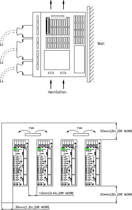
2.1.3.Orientation
Install the servo amplifier perpendicular to the wall as shown in the figure. The servo amplifier must be oriented this way because it is designed to be cooled by natural convection or by a cooling fan.
Secure the servo amplifier using the mounting holes. The number of holes varies (from two to four) with the frame size of the servo amplifier.
2.1.4.Installation
Follow the procedure below to install multiple servo amplifiers side by side in a control panel.
2-3
XtraDrive User Manual |
Chapter 2: Installation |
Servo Amplifier Orientation
Install the servo amplifier perpendicular to the wall so the front panels’ connectors faces outward.
Cooling
As shown in the figure above, allow sufficient space around each servo amplifier for cooling by cooling fans or natural convection.
Side-by-side Installation
When installing servo amplifiers side by side as shown in the figure above, allow at least 0.39in (10mm) between and at least 1.97in (50mm) above and below each servo amplifier. Install cooling fans above the servo amplifiers to avoid excessive temperature rise and to maintain even temperature inside the control panel.
Environmental Conditions in the Control Panel
• |
Ambient Temperature: |
0 to 55°C |
• |
Humidity: |
90% RH or less |
• |
Vibration: |
0.5 G (4.9m/s2) |
• |
Condensation and Freezing: |
None |
•Ambient Temperature for Long-term Reliability: 45°C max.
2-4
XtraDrive User Manual |
Chapter 3: Wiring |
3. Wiring
This chapter describes the procedure used to connect XtraDrive Series products to peripheral devices and gives typical examples of main circuit wiring as well as I/O signal connections.
3.1. |
Connecting to Peripheral Devices............................................................... |
3-2 |
|
3.1.1. |
Single-Phase 200V Main Circuit Specifications................................. |
3-3 |
|
3.1.2. |
Single-Phase 0.8kW 200V Main Circuit Specifications..................... |
3-4 |
|
3.1.3. |
Three-phase 200V Main Circuit Specifications.................................. |
3-5 |
|
3.1.4. |
Three-Phase 400V Main Circuit Specifications ................................. |
3-6 |
|
3.2. |
XtraDrive Internal Block Diagrams............................................................ |
3-7 |
|
3.2.1. |
Single-phase 30W to 800W, 200V Models ........................................ |
3-7 |
|
3.2.2. |
Three-phase 1kW to 3kW, 200V Models ........................................... |
3-8 |
|
3.2.3. |
Three-phase 0.5kW to 3.0kW, 400V Models ..................................... |
3-9 |
|
3.3. |
Main Circuit Wiring.................................................................................. |
3-10 |
|
3.3.1. |
Names and Descriptions of Main Circuit Terminal .......................... |
3-11 |
|
3.3.2. |
Typical Main Circuit Wiring Example ............................................. |
3-12 |
|
3.3.3. |
Servo Amplifier Power Losses ......................................................... |
3-13 |
|
3.3.4. |
Wiring Main Circuit Terminal Blocks .............................................. |
3-14 |
|
3.4. |
I/O Signals ................................................................................................ |
3-15 |
|
3.4.1. |
Example of Typical I/O Signal Connections .................................... |
3-15 |
|
3.4.2. |
List of CN1 Terminals ...................................................................... |
3-16 |
|
3.4.3. |
I/O Signal Names and Functions ...................................................... |
3-17 |
|
3.4.4. |
Interface Circuits............................................................................... |
3-19 |
|
3.5. Wiring Encoders (for SGMGH and SGMSH Motors Only) .................... |
3-23 |
||
3.5.1. |
Encoder Connections ........................................................................ |
3-23 |
|
3.5.2. |
CN2 Encoder Connector Terminal Layout and Types ..................... |
3-25 |
|
3.5.3. |
Encoder Cables Interconnections...................................................... |
3-26 |
|
3.6. Examples of Standard Connections .......................................................... |
3-28 |
||
3-1
XtraDrive User Manual |
Chapter 3: Wiring |
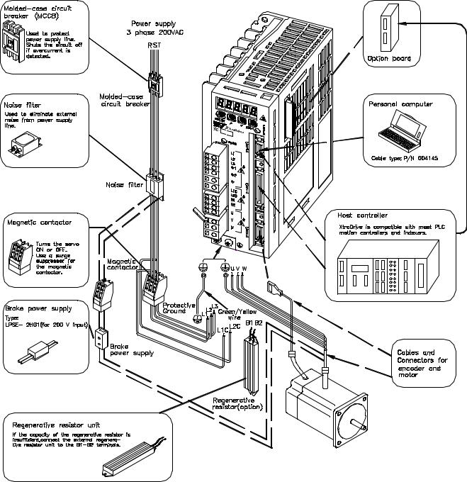
3.1. Connecting to Peripheral Devices
This section provides examples of standard XtraDrive Series product connections to peripheral devices.
It also briefly explains how to connect each peripheral device.
3-2

XtraDrive User Manual |
Chapter 3: Wiring |
3.1.1.Single-Phase 200V Main Circuit Specifications
3-3

XtraDrive User Manual |
Chapter 3: Wiring |
3.1.2.Single-Phase 0.8kW 200V Main Circuit Specifications
XtraDrive XD-08-MS has been changed from three-phase specifications to singlephase. Main circuit connection terminals (L1, L2, L3) remained.
These devices have terminal B3 and internal regenerative resistor. Observe the following points.
1.Connect main power supply shown below to L1 and L3 terminals. Power supply is single-phase, 220 to 230 VAC +10% to –15%, 50/60Hz. If power supply of 187V (-15% of 220V) or less is used, alarm A.41 indicating voltage shortage, may occur when accelerating to max speed with max torque of motor.
2.Short-circuit B2 and B3 terminals using the internal regenerative resistor. If capacity of the regenerative resistor is insufficient, remove the lead between B2 and B3 terminals and connect an external regenerative resistor unit to B1 and B2 terminals.
3-4
XtraDrive User Manual |
Chapter 3: Wiring |
3.1.3.Three-phase 200V Main Circuit Specifications
3-5

XtraDrive User Manual |
Chapter 3: Wiring |
3.1.4.Three-Phase 400V Main Circuit Specifications
3-6
Loading...