


 Loading...
Omron SRT2, CQM1-SRM21-V1, SRT1, CS1W-SRM21, COMPOBUS-S OPERATION MANUAL
...Cat. No. W266-E1-09
C200HW-SRM21-V1
CS1W-SRM21
CJ1W-SRM21
CQM1-SRM21-V1
SRT1 Series
SRT2 Series
CompoBus/S
OPERATION MANUAL
C200HW-SRM21-V1 CS1W-SRM21 CJ1W-SRM21 CQM1-SRM21-V1 SRT1 Series
SRT2 Series
CompoBus/S
Operation Manual
Revised August 2007
Notice:
OMRON products are manufactured for use according to proper procedures by a qualified operator and only for the purposes described in this manual.
The following conventions are used to indicate and classify precautions in this manual. Always heed the information provided with them. Failure to heed precautions can result in injury to people or damage to property.
!DANGER Indicates an imminently hazardous situation which, if not avoided, will result in death or serious injury. Additionally, there may be severe property damage.
!WARNING Indicates a potentially hazardous situation which, if not avoided, could result in death or serious injury. Additionally, there may be severe property damage.
!Caution Indicates a potentially hazardous situation which, if not avoided, may result in minor or moderate injury, or property damage.
OMRON Product References
All OMRON products are capitalized in this manual. The word “Unit” is also capitalized when it refers to an OMRON product, regardless of whether or not it appears in the proper name of the product.
The abbreviation “Ch,” which appears in some displays and on some OMRON products, often means “word” and is abbreviated “Wd” in documentation in this sense.
The abbreviation “PLC” means Programmable Controller and is not used as an abbreviation for anything else.
Visual Aids
The following headings appear in the left column of the manual to help you locate different types of information.
Note Indicates information of particular interest for efficient and convenient operation of the product.
1,2,3... 1. Indicates lists of one sort or another, such as procedures, checklists, etc.
OMRON, 1996
All rights reserved. No part of this publication may be reproduced, stored in a retrieval system, or transmitted, in any form, or by any means, mechanical, electronic, photocopying, recording, or otherwise, without the prior written permission of OMRON.
No patent liability is assumed with respect to the use of the information contained herein. Moreover, because OMRON is constantly striving to improve its high-quality products, the information contained in this manual is subject to change without notice. Every precaution has been taken in the preparation of this manual. Nevertheless, OMRON assumes no responsibility for errors or omissions. Neither is any liability assumed for damages resulting from the use of the information contained in this publication.
v
TABLE OF CONTENTS
PRECAUTIONS . . . . . . . . . . . . . . . . . . . . . . . . . . . . . . . . |
xv |
|
1 |
Intended Audience . . . . . . . . . . . . . . . . . . . . . . . . . . . . . . . . . . . . . . . . . . . . . . . . . |
xvi |
2 |
General Precautions . . . . . . . . . . . . . . . . . . . . . . . . . . . . . . . . . . . . . . . . . . . . . . . . |
xvi |
3 |
Safety Precautions. . . . . . . . . . . . . . . . . . . . . . . . . . . . . . . . . . . . . . . . . . . . . . . . . . |
xvi |
4 |
Operating Environment Precautions . . . . . . . . . . . . . . . . . . . . . . . . . . . . . . . . . . . . |
xvii |
5 |
Application Precautions . . . . . . . . . . . . . . . . . . . . . . . . . . . . . . . . . . . . . . . . . . . . . |
xviii |
6 Conformance to EC Directives . . . . . . . . . . . . . . . . . . . . . . . . . . . . . . . . . . . . . . . . |
xxi |
|
SECTION 1 |
|
|
System Design . . . . . . . . . . . . . . . . . . . . . . . . . . . . . . . . . . |
1 |
|
1-1 System Overview and Features . . . . . . . . . . . . . . . . . . . . . . . . . . . . . . . . . . . . . . . . |
2 |
|
1-2 |
CompoBus/S System Configuration . . . . . . . . . . . . . . . . . . . . . . . . . . . . . . . . . . . . |
6 |
1-3 |
Compatible Devices . . . . . . . . . . . . . . . . . . . . . . . . . . . . . . . . . . . . . . . . . . . . . . . . |
10 |
1-4 |
Startup Procedure . . . . . . . . . . . . . . . . . . . . . . . . . . . . . . . . . . . . . . . . . . . . . . . . . . |
20 |
SECTION 2 |
|
|
CompoBus/S System Specifications and Configuration |
23 |
|
2-1 |
Communications Specifications . . . . . . . . . . . . . . . . . . . . . . . . . . . . . . . . . . . . . . . |
24 |
2-2 |
System Configuration . . . . . . . . . . . . . . . . . . . . . . . . . . . . . . . . . . . . . . . . . . . . . . . |
25 |
2-3 Supplying Power to the Slaves . . . . . . . . . . . . . . . . . . . . . . . . . . . . . . . . . . . . . . . . |
31 |
|
2-4 System Configuration Using Water-resistant Terminals . . . . . . . . . . . . . . . . . . . . . |
41 |
|
2-5 I/O Response Time Characteristics . . . . . . . . . . . . . . . . . . . . . . . . . . . . . . . . . . . . . |
41 |
|
SECTION 3 |
|
|
CompoBus/S System Wiring . . . . . . . . . . . . . . . . . . . . . . |
53 |
|
3-1 |
Mounting . . . . . . . . . . . . . . . . . . . . . . . . . . . . . . . . . . . . . . . . . . . . . . . . . . . . . . . . . |
54 |
3-2 Connector Installation (Special Flat Cable Only) . . . . . . . . . . . . . . . . . . . . . . . . . . |
55 |
|
3-3 |
VCTF Cable Assembly . . . . . . . . . . . . . . . . . . . . . . . . . . . . . . . . . . . . . . . . . . . . . . |
64 |
3-4 |
Master/Slave Connecting Cables . . . . . . . . . . . . . . . . . . . . . . . . . . . . . . . . . . . . . . |
66 |
3-5 |
Operations Checklist . . . . . . . . . . . . . . . . . . . . . . . . . . . . . . . . . . . . . . . . . . . . . . . . |
70 |
SECTION 4 |
|
|
Master Unit Specifications and Operations . . . . . . . . . . |
73 |
|
4-1 |
C200HW-SRM21-V1 Master Unit for CS-series, |
|
|
C200HX/C200HG/C200HE-(Z)E, and C200HS PLCs . . . . . . . . . . . . . . . . . . . . . |
74 |
4-2 CS1W-SRM21 Master Unit for CS-series PLCs . . . . . . . . . . . . . . . . . . . . . . . . . . |
88 |
|
4-3 CJ1W-SRM21 Master Unit for CJ-series PLCs . . . . . . . . . . . . . . . . . . . . . . . . . . . |
104 |
|
4-4 CQM1-SRM21-V1 Master Unit for CQM1 PLCs . . . . . . . . . . . . . . . . . . . . . . . . . |
126 |
|
4-5 SRM1-C0@-V2 Master Control Units . . . . . . . . . . . . . . . . . . . . . . . . . . . . . . . . . . |
136 |
|
4-6 |
CPM2C-S Series CPM2C-S@@@C (-DRT). . . . . . . . . . . . . . . . . . . . . . . . . . . . . . |
140 |
vii
TABLE OF CONTENTS
SECTION 5 |
|
|
Slave Specifications and Operations . . . . . . . . . . . . . . . . |
145 |
|
5-1 |
Remote Terminals . . . . . . . . . . . . . . . . . . . . . . . . . . . . . . . . . . . . . . . . . . . . . . . . . |
147 |
5-2 |
Connector Terminals . . . . . . . . . . . . . . . . . . . . . . . . . . . . . . . . . . . . . . . . . . . . . . . |
194 |
5-3 |
Remote I/O Modules . . . . . . . . . . . . . . . . . . . . . . . . . . . . . . . . . . . . . . . . . . . . . . . |
260 |
5-4 |
Water-resistant Terminals . . . . . . . . . . . . . . . . . . . . . . . . . . . . . . . . . . . . . . . . . . . |
268 |
5-5 |
Sensor Terminals . . . . . . . . . . . . . . . . . . . . . . . . . . . . . . . . . . . . . . . . . . . . . . . . . . |
287 |
5-6 |
Fiber Amplifier Communications Units . . . . . . . . . . . . . . . . . . . . . . . . . . . . . . . . |
301 |
5-7 |
Analog Input Terminals . . . . . . . . . . . . . . . . . . . . . . . . . . . . . . . . . . . . . . . . . . . . . |
308 |
5-8 |
Analog Output Terminals . . . . . . . . . . . . . . . . . . . . . . . . . . . . . . . . . . . . . . . . . . . |
318 |
5-9 |
I/O Link Units for CPM1A and CPM2A. . . . . . . . . . . . . . . . . . . . . . . . . . . . . . . . |
327 |
5-10 |
I/O Link Units for CPM2C . . . . . . . . . . . . . . . . . . . . . . . . . . . . . . . . . . . . . . . . . . |
331 |
5-11 |
Sensor Amplifier Terminals. . . . . . . . . . . . . . . . . . . . . . . . . . . . . . . . . . . . . . . . . . |
335 |
5-12 |
Application Precautions. . . . . . . . . . . . . . . . . . . . . . . . . . . . . . . . . . . . . . . . . . . . . |
350 |
SECTION 6 |
|
|
Starting Communications. . . . . . . . . . . . . . . . . . . . . . . . . |
353 |
|
6-1 |
Turning the Power ON. . . . . . . . . . . . . . . . . . . . . . . . . . . . . . . . . . . . . . . . . . . . . . |
354 |
6-2 |
Checking Operations for CS-series, C200HX/C200HG/C200HE-(Z)E, |
|
|
and C200HS Master Units . . . . . . . . . . . . . . . . . . . . . . . . . . . . . . . . . . . . . . . . . . . |
356 |
6-3 |
Checking Operations of CS-series and CJ-series Master Units. . . . . . . . . . . . . . . |
365 |
6-4 |
Checking Operations of CQM1 Master Units . . . . . . . . . . . . . . . . . . . . . . . . . . . . |
377 |
6-5 |
Checking Slave Operations . . . . . . . . . . . . . . . . . . . . . . . . . . . . . . . . . . . . . . . . . . |
382 |
6-6 |
Cleaning and Inspection . . . . . . . . . . . . . . . . . . . . . . . . . . . . . . . . . . . . . . . . . . . . |
384 |
6-7 |
Precautions for Replacement of Units or Parts . . . . . . . . . . . . . . . . . . . . . . . . . . . |
385 |
Appendix |
|
|
Standard Models . . . . . . . . . . . . . . . . . . . . . . . . . . . . . . . . . . . . . . . . . . . . . . . . . . . . . . . |
387 |
|
Index . . |
. . . . . . . . . . . . . . . . . . . . . . . . . . . . . . . . . . . . . . . . |
395 |
Revision History . . . . . . . . . . . . . . . . . . . . . . . . . . . . . . . . |
401 |
|
viii
About this Manual:
This manual describes the installation and operation of the CompoBus/S system and includes the sections described below.
Please read this manual carefully and be sure you understand the information provided before attempting to install and operate the CompoBus/S Master and Slave Units. Be sure to read the precautions provided in the following section.
Section 1 provides an overview of the CompoBus/S System and functions, and describes the various Units that are used to configure a CompoBus/S System.
Section 2 provides details on the CompoBus/S System specifications and I/O response times, and explains how to configure a CompoBus/S System.
Section 3 explains how to install Units in control panels, wire the signal and power lines, and make other connections needed to assemble a CompoBus/S System. We recommend reading through the information on wiring each Master and Slave that are provided in Section 4 and Section 5.
Section 4 explains the functions of each Master Unit, including information on specifications, switch settings and allocation of Slave I/O.
Section 5 explains the functions of each Slave, including information on specifications, switch settings, and I/O.
Section 6 provides information on error processing, periodic maintenance operations, and troubleshooting procedures needed to keep the CompoBus/S System operating properly. We recommend reading through the error processing procedures before operation so that operating errors can be identified and corrected more quickly.
The Appendix provides tables of standard models including Masters, Slaves, and connecting devices.
In this manual, only the specifications of the CompoBus/S system and devices are described. For details on Units, refer to their respective manuals. (Suffixes have been omitted from the catalog numbers.)
Product Name |
Series |
Manual Name |
Cat. No. |
|
|
|
|
CS-series Programmable Controllers |
CS Series |
SYSMAC CS Series Operation |
W339 |
|
|
Manual |
|
|
|
|
|
CJ-series Programmable Controllers |
CJ Series |
SYSMAC CJ Series Operation |
W393 |
|
|
Manual |
|
|
|
|
|
CS/CJ-series Programmable Control- |
CS/CJ Series |
SYSMAC CS/CJ Series Pro- |
W394 |
lers |
|
gramming Manual |
|
|
|
|
|
C200HX/C200HG/C200HE-(Z)E Pro- |
C200HX/C200HG/ |
SYSMAC C200HX/C200HG/ |
W302 |
grammable Controllers |
C200HE-(Z)E |
C200HE-(Z)E Programmable |
|
|
|
Controllers Installation Guide |
|
|
|
|
|
C200HX/C200HG/C200HE-(Z)E Pro- |
C200HX/C200HG/ |
SYSMAC C200HX/C200HG/ |
W322 |
grammable Controllers |
C200HE-(Z)E |
C200HE-(Z)E Programmable |
|
|
|
Controllers Operation Manual |
|
|
|
|
|
C200HS Programmable Controllers |
C200HS |
SYSMAC C200HS Operation |
W235 |
|
|
Manual |
|
|
|
|
|
C200HS Programmable Controllers |
C200HS |
SYSMAC C200HS Installation |
W236 |
|
|
Guide |
|
|
|
|
|
CQM1H Programmable Controller |
CQM1H |
SYSMAC CQM1H Operation |
W363 |
|
|
Manual |
|
|
|
|
|
CQM1H Programmable Controller |
CQM1H |
SYSMAC CQM1H Programming |
W364 |
|
|
Manual |
|
|
|
|
|
CQM1 Programmable Controller |
CQM1 |
SYSMAC CQM1 Operation Man- |
W226 |
|
|
ual |
|
|
|
|
|
ix

Product Name |
Series |
Manual Name |
Cat. No. |
|
|
|
|
CQM1/CPM1/CPM1A/SRM1 Pro- |
CQM1/CPM1/ |
SYSMAC CQM1/CPM1/CPM1A/ |
W228 |
grammable Controller |
CPM1A/SRM1 |
SRM1 Programming Manual |
|
|
|
|
|
CompoBus/S SRM1 Master Control |
SRM1(-V2) |
SYSMAC CompoBus/S SRM1 |
W318 |
Unit |
|
Master Control Units Operation |
|
|
|
Manual |
|
|
|
|
|
CPM2C-S Programmable Controller |
CPM2C-S |
SYSMAC CPM2C-S Programma- |
W377 |
|
|
ble Controllers Operation Manual |
|
|
|
|
|
CPM1A/CPM2A I/O Link Unit |
CPM1A-SRT21 |
SYSMAC CPM2A I/O Link Units |
W352 |
|
|
Operation Manual |
|
|
|
|
|
CPM2C I/O Link Unit |
CPM2C-SRT21 |
SYSMAC CPM2C I/O Link Units |
W356 |
|
|
Operation Manual |
|
|
|
|
|
!WARNING Failure to read and understand the information provided in this manual may result in personal injury or death, damage to the product, or product failure. Please read each section in its entirety and be sure you understand the information provided in the section and related sections before attempting any of the procedures or operations given.
x

Read and Understand this Manual
Please read and understand this manual before using the product. Please consult your OMRON representative if you have any questions or comments.
Warranty and Limitations of Liability
WARRANTY
OMRON's exclusive warranty is that the products are free from defects in materials and workmanship for a period of one year (or other period if specified) from date of sale by OMRON.
OMRON MAKES NO WARRANTY OR REPRESENTATION, EXPRESS OR IMPLIED, REGARDING NONINFRINGEMENT, MERCHANTABILITY, OR FITNESS FOR PARTICULAR PURPOSE OF THE PRODUCTS. ANY BUYER OR USER ACKNOWLEDGES THAT THE BUYER OR USER ALONE HAS DETERMINED THAT THE PRODUCTS WILL SUITABLY MEET THE REQUIREMENTS OF THEIR INTENDED USE. OMRON DISCLAIMS ALL OTHER WARRANTIES, EXPRESS OR IMPLIED.
LIMITATIONS OF LIABILITY
OMRON SHALL NOT BE RESPONSIBLE FOR SPECIAL, INDIRECT, OR CONSEQUENTIAL DAMAGES, LOSS OF PROFITS OR COMMERCIAL LOSS IN ANY WAY CONNECTED WITH THE PRODUCTS, WHETHER SUCH CLAIM IS BASED ON CONTRACT, WARRANTY, NEGLIGENCE, OR STRICT LIABILITY.
In no event shall the responsibility of OMRON for any act exceed the individual price of the product on which liability is asserted.
IN NO EVENT SHALL OMRON BE RESPONSIBLE FOR WARRANTY, REPAIR, OR OTHER CLAIMS REGARDING THE PRODUCTS UNLESS OMRON'S ANALYSIS CONFIRMS THAT THE PRODUCTS WERE PROPERLY HANDLED, STORED, INSTALLED, AND MAINTAINED AND NOT SUBJECT TO CONTAMINATION, ABUSE, MISUSE, OR INAPPROPRIATE MODIFICATION OR REPAIR.
xi
Application Considerations
SUITABILITY FOR USE
OMRON shall not be responsible for conformity with any standards, codes, or regulations that apply to the combination of products in the customer's application or use of the products.
At the customer's request, OMRON will provide applicable third party certification documents identifying ratings and limitations of use that apply to the products. This information by itself is not sufficient for a complete determination of the suitability of the products in combination with the end product, machine, system, or other application or use.
The following are some examples of applications for which particular attention must be given. This is not intended to be an exhaustive list of all possible uses of the products, nor is it intended to imply that the uses listed may be suitable for the products:
•Outdoor use, uses involving potential chemical contamination or electrical interference, or conditions or uses not described in this manual.
•Nuclear energy control systems, combustion systems, railroad systems, aviation systems, medical equipment, amusement machines, vehicles, safety equipment, and installations subject to separate industry or government regulations.
•Systems, machines, and equipment that could present a risk to life or property.
Please know and observe all prohibitions of use applicable to the products.
NEVER USE THE PRODUCTS FOR AN APPLICATION INVOLVING SERIOUS RISK TO LIFE OR PROPERTY WITHOUT ENSURING THAT THE SYSTEM AS A WHOLE HAS BEEN DESIGNED TO ADDRESS THE RISKS, AND THAT THE OMRON PRODUCTS ARE PROPERLY RATED AND INSTALLED FOR THE INTENDED USE WITHIN THE OVERALL EQUIPMENT OR SYSTEM.
PROGRAMMABLE PRODUCTS
OMRON shall not be responsible for the user's programming of a programmable product, or any consequence thereof.
xii

Disclaimers
CHANGE IN SPECIFICATIONS
Product specifications and accessories may be changed at any time based on improvements and other reasons.
It is our practice to change model numbers when published ratings or features are changed, or when significant construction changes are made. However, some specifications of the products may be changed without any notice. When in doubt, special model numbers may be assigned to fix or establish key specifications for your application on your request. Please consult with your OMRON representative at any time to confirm actual specifications of purchased products.
DIMENSIONS AND WEIGHTS
Dimensions and weights are nominal and are not to be used for manufacturing purposes, even when tolerances are shown.
PERFORMANCE DATA
Performance data given in this manual is provided as a guide for the user in determining suitability and does not constitute a warranty. It may represent the result of OMRON's test conditions, and the users must correlate it to actual application requirements. Actual performance is subject to the OMRON Warranty and Limitations of Liability.
ERRORS AND OMISSIONS
The information in this manual has been carefully checked and is believed to be accurate; however, no responsibility is assumed for clerical, typographical, or proofreading errors, or omissions.
xiii
PRECAUTIONS
This section provides general precautions for using the CompoBus/S Units, Programmable Controllers, and related devices.
The information contained in this section is important for the safe and reliable application of the CompoBus/S and PLC. You must read this section and understand the information contained before attempting to set up or operate a CompoBus/S and PLC system.
1 |
Intended Audience . . . . . . . . . . . . . . . . . . . . . . . . . . . . . . . . . . . . . . . . . . . . . |
xvi |
|
2 |
General Precautions . . . . . . . . . . . . . . . . . . . . . . . . . . . . . . . . . . . . . . . . . . . . |
xvi |
|
3 |
Safety Precautions. . . . . . . . . . . . . . . . . . . . . . . . . . . . . . . . . . . . . . . . . . . . . . |
xvi |
|
4 |
Operating Environment Precautions . . . . . . . . . . . . . . . . . . . . . . . . . . . . . . . . |
xvii |
|
5 |
Application Precautions . . . . . . . . . . . . . . . . . . . . . . . . . . . . . . . . . . . . . . . . . |
xviii |
|
6 |
Conformance to EC Directives . . . . . . . . . . . . . . . . . . . . . . . . . . . . . . . . . . . . |
xxi |
|
|
6-1 |
Applicable Directives . . . . . . . . . . . . . . . . . . . . . . . . . . . . . . . . . . . . |
xxi |
|
6-2 |
Concepts . . . . . . . . . . . . . . . . . . . . . . . . . . . . . . . . . . . . . . . . . . . . . . |
xxi |
|
6-3 |
Conformance to EC Directives . . . . . . . . . . . . . . . . . . . . . . . . . . . . . |
xxi |
xv

Intended Audience |
1 |
1 Intended Audience
This manual is intended for the following personnel, who must also have knowledge of electrical systems (an electrical engineer or the equivalent).
•Personnel in charge of installing FA systems.
•Personnel in charge of designing FA systems.
•Personnel in charge of managing FA systems and facilities.
2 General Precautions
The user must operate the product according to the performance specifications described in the operation manuals.
Before using the product under conditions which are not described in the manual or applying the product to nuclear control systems, railroad systems, aviation systems, vehicles, combustion systems, medical equipment, amusement machines, safety equipment, and other systems, machines, and equipment that may have a serious influence on lives and property if used improperly, consult your OMRON representative.
Make sure that the ratings and performance characteristics of the product are sufficient for the systems, machines, and equipment, and be sure to provide the systems, machines, and equipment with double safety mechanisms.
This manual provides information for installing and operating OMRON CompoBus/S Units. Be sure to read this manual before operation and keep this manual close at hand for reference during operation.
!WARNING It is extremely important that a PLC and all PLC Units be used for the specified purpose and under the specified conditions, especially in applications that can directly or indirectly affect human life. You must consult with your OMRON representative before applying a PLC System to the above-mentioned applications.
3 Safety Precautions
!WARNING Do not attempt to take any Unit apart while the power is being supplied. Doing so may result in electric shock.
!WARNING Do not touch any of the terminals or terminal blocks while the power is being supplied. Doing so may result in electric shock.
!WARNING Provide safety measures in external circuits, i.e., not in the Programmable Controller (CPU Unit including associated Units; referred to as “PLC”), in order to ensure safety in the system if an abnormality occurs due to malfunction of the PLC or another external factor affecting the PLC operation. Not doing so may result in serious accidents.
•Emergency stop circuits, interlock circuits, limit circuits, and similar safety measures must be provided in external control circuits.
•The PLC will turn OFF all outputs when its self-diagnosis function detects any error or when a severe failure alarm (FALS) instruction is executed. As a countermeasure for such errors, external safety measures must be provided to ensure safety in the system.
xvi

Operating Environment Precautions |
4 |
•The PLC outputs may remain ON or OFF due to deposition or burning of the output relays or destruction of the output transistors. As a countermeasure for such problems, external safety measures must be provided to ensure safety in the system.
•When the 24-VDC output (service power supply to the PLC) is overloaded or short-circuited, the voltage may drop and result in the outputs being turned OFF. As a countermeasure for such problems, external safety measures must be provided to ensure safety in the system.
!WARNING Do not attempt to disassemble, repair, or modify any Units. Any attempt to do so may result in malfunction, fire, or electric shock.
!Caution Execute online edit only after confirming that no adverse effects will be caused by extending the cycle time. Otherwise, the input signals may not be readable.
!Caution Confirm safety at the destination node before transferring a program to another node or editing the I/O area. Doing either of these without confirming safety may result in injury.
!Caution Tighten the screws on the terminal block of the AC Power Supply Unit to the torque specified in the operation manual. The loose screws may result in burning or malfunction.
4 Operating Environment Precautions
!Caution Do not operate the control system in the following places:
•Locations subject to direct sunlight
•Locations subject to temperatures or humidity outside the range specified in the specifications
•Locations subject to condensation as the result of severe changes in temperature
•Locations subject to corrosive or flammable gases
•Locations subject to dust (especially iron dust) or salts
•Locations subject to exposure to water, oil, or chemicals
•Locations subject to shock or vibration
!Caution Take appropriate and sufficient countermeasures when installing systems in the following locations:
•Locations subject to static electricity or other forms of noise
•Locations subject to strong electromagnetic fields
•Locations subject to possible exposure to radioactivity
•Locations close to power supplies
xvii

Application Precautions |
5 |
!Caution The operating environment of the PLC System can have a large effect on the longevity and reliability of the system. Improper operating environments can lead to malfunction, failure, and other unforeseeable problems with the PLC System. Be sure that the operating environment is within the specified conditions at installation and remains within the specified conditions during the life of the system.
5 Application Precautions
Observe the following precautions when using the CompoBus/S Units or the
PLC.
!WARNING Failure to abide by the following precautions could lead to serious or possibly fatal injury. Always heed these precautions.
•Always connect to 100 Ω or less when installing the Units. Not connecting to a ground of 100 Ω or less may result in electric shock.
•Always turn OFF the power supplies to the PLC, slaves, and communications before attempting any of the following. Not turning OFF the power supplies may result in malfunction or electric shock.
•Mounting or dismounting Power Supply Units, I/O Units, CPU Units, memory casettes, Master Units, or any other Units
•Mounting or dismounting circuits for Remote I/O Terminals with 3-tier terminal blocks
•Assembling the Units or Racks
•Setting DIP switches or rotary switches
•Connecting or wiring the cables
•Connecting or disconnecting the connectors
!Caution Failure to abide by the following precautions could lead to faulty operation or the PLC or the system or could damage the PLC or PLC Units. Always heed these precautions.
•Failsafe measures must be taken by the customer to ensure safety in the event of incorrect, missing, or abnormal signals caused by broken signal lines, momentary power interruptions, or other causes.
•Provide external interlock circuits, limit circuits, and other safety circuits in addition to any provided within the PLC to ensure safety.
•Configure the control circuits to turn ON the power supply to I/O slaves before turning ON the power supply to the PLC (Master Unit). If the I/O slave power supply is turned ON after the PLC, correct operation may temporarily not be possible.
•Do not attempt to disassemble, repair, or modify any Units. Any attempt to do so may result in malfunction, fire, or electric shock.
•Do not drop the Unit or subject it to excessive vibration or shock.
•Be sure that all the Backplane mounting screws, slave mounting screws, terminal screws, and cable connector screws are tightened to the torque specified in the relevant manuals. Incorrect tightening torque may result in malfunction.
•Wire correctly according to specified procedures.
xviii

Application Precautions |
5 |
•Pay careful attention to the polarity (+/−) when connecting the terminal blocks or connectors. Wrong connections may cause malfunction of the system.
•Wire all terminals, communications paths, power supplies lines, and I/O lines with the specified polarity and voltages. Improper wiring may result in faulty operation.
•Install external breakers and take other safety measures against short-cir- cuiting in external wiring. Insufficient safety measures against short-cir- cuiting may result in burning.
•Do not mount the Unit near equipment that generates strong high-fre- quency noise.
•Leave the label attached to the Unit when wiring to prevent wire clippings and other foreign matter from entering the Unit. Removing the label may result in malfunction.
•Remove the label after the completion of wiring to ensure proper heat dissipation. Leaving the label attached may result in malfunction.
•Use crimp terminals for wiring. Do not connect bare stranded wires directly to terminals. Connection of bare stranded wires may result in burning.
•Wire correctly and double-check all the wiring or the setting switches before turning ON the power supply. Incorrect wiring may result in burning.
•Be sure that the terminal blocks, connectors, expansion cables, and other items with locking devices are properly locked into place. Improper locking may result in malfunction.
•Disconnect the LG and GR terminals on the Power Supply Unit before performing insulation resistance or dielectric strength tests.
•Always use the power supply voltage specified in the operation manual. An incorrect voltage may result in malfunction or burning.
•Take appropriate measures to ensure that the specified power with the rated voltage and frequency is supplied. Be particularly careful in places where the power supply is unstable. An incorrect power supply may result in malfunction.
•Do not apply voltages to the Input Units in excess of the rated input voltage. Excess voltages may result in burning.
•Do not apply voltages exceeding the maximum switching capacity to Output Units. The Output Units may be destroyed.
•Check the user program for proper execution before actually running it on the Unit. Not checking the program may result in an unexpected operation.
•Always turn OFF the power supplies to the PLC, slaves, and communications before attempting any of the following. Not turning OFF the power supply may result in malfunction or electric shock.
•Mounting or dismounting Power Supply Units, I/O Units, CPU Units, memory casettes Master Unit, or any other Units
•Mounting or dismounting circuits for Remote I/O Terminals with 3-tier terminal blocks.
•Assembling the Units
•Setting DIP switches or rotary switches
•Connecting or wiring the cables
xix

Application Precautions |
5 |
•Connecting or disconnecting the connectors
•Before touching the Unit, be sure to first touch a grounded metallic object in order to discharge any static built-up. Not doing so may result in malfunction or damage.
•Confirm that no adverse effect will occur in the system before attempting any of the following. Not doing so may result in an unexpected operation.
•Changing the operating mode of the PLC. (including the Startup Mode setting)
•Force-setting/force-resetting any bit in memory.
•Changing the present value of any word or any set value in memory.
•When replacing parts, be sure to confirm that the rating of a new part is correct. Not doing so may result in malfunction or burning.
•Resume operation only after transferring to the new CPU Unit and/or Special I/O Units the contents of the DM and HR Areas required for resuming operation. Not doing so may result in an unexpected operation.
•When transporting the Units, use special packing boxes and protect them from excessive vibration or shock during transportation.
•Connect all communications cables within the limits given in the specifications.
•Observe the following precautions when wiring communications cables.
•Separate the communications cables from power lines or high-tension lines.
•Do not bend the communications cables.
•Do not pull on the communications cables with an excessive force.
•Do not place heavy objects on the communications cables.
•Be sure to put the communications cables inside conduits.
•Water-resistant Terminals used as Slaves are of IP67 construction. Do not attempt to use the Watertight Terminals for applications where the Watertight Terminals are always underwater.
•Install the Unit properly as specified in the operation manual. Improper installation of the Unit may result in malfunction.
xx

Conformance to EC Directives |
6 |
6 Conformance to EC Directives
6-1 Applicable Directives
• EMC Directives
6-2 Concepts
EMC Directives
OMRON devices that comply with EC Directives also conform to the related EMC standards so that they can be more easily built into other devices or the overall machine. The actual products have been checked for conformity to EMC standards (see the following note). Whether the products conform to the standards in the system used by the customer, however, must be checked by the customer.
EMC-related performance of the OMRON devices that comply with EC Directives will vary depending on the configuration, wiring, and other conditions of the equipment or control panel on which the OMRON devices are installed. The customer must, therefore, perform the final check to confirm that devices and the overall machine conform to EMC standards.
Note Applicable EMC (Electromagnetic Compatibility) standards are listed in the following table.
Unit |
EMS (Electromagnetic |
EMI (Electromagnetic |
|
Susceptibility) |
Interference) |
|
|
|
C200HW-SRM21-V1 |
EN61131-2 |
EN61000-6-4 (See note 2.) |
|
|
|
CS1W-SRM21 |
EN61131-2 |
|
|
|
|
CJ1W-SRM21 |
EN61000-6-2 (See note 1.) |
|
|
|
|
CQM1-SRM21-V1 |
EN61131-2 |
|
|
|
|
SRM1-C0@-V2 |
EN61000-6-2 (See note 1.) |
|
|
|
|
CPM2C-S@@@C(-DRT) |
EN61131-2 |
|
|
|
|
SRT1 and SRT2 Series |
EN61000-6-2 (See note 1.) |
|
|
|
|
Note 1. These products have configurations with less than 30 m of I/O wiring, and less than 10 m of power supply wiring.
2. Radiated emission for EN61000-6-4: 10-m regulations
6-3 Conformance to EC Directives
Observe the follow precautions when installing the CompoBus/S Units that conform to the EC Directives.
1,2,3... 1. Since the CompoBus/S Units are classified as built-in types, be sure to install the Units inside a control panel.
2.Provide reinforced insulation or double insulation for the DC Power Supplies that are used as power sources for the alarm output, communications circuits, and I/O circuits.
3.The CompoBus/S Units that conform to the EC Directives also conforms to the Common Emission Standard (EN61000-6-4). When incorporated into a device, however, the requirements may vary depending on the configuration of the control panel to be used, relationship with other devices to be connected, wiring, etc. Users are therefore requested to confirm Unit conformance to the EC Directives by themselves.
xxi
SECTION 1
System Design
This section provides an overview of the CompoBus/S System and functions, and describes the various Masters, Slaves, and connection devices that are used to configure a CompoBus/S System.
1-1 |
System Overview and Features . . . . . . . . . . . . . . . . . . . . . . . . . . . . . . . . . . . . |
2 |
|
|
1-1-1 |
System Overview . . . . . . . . . . . . . . . . . . . . . . . . . . . . . . . . . . . . . . . |
2 |
|
1-1-2 |
Network Features . . . . . . . . . . . . . . . . . . . . . . . . . . . . . . . . . . . . . . . |
3 |
|
1-1-3 |
Communications Modes . . . . . . . . . . . . . . . . . . . . . . . . . . . . . . . . . . |
5 |
1-2 |
CompoBus/S System Configuration . . . . . . . . . . . . . . . . . . . . . . . . . . . . . . . . |
6 |
|
|
1-2-1 |
Basic System Configuration . . . . . . . . . . . . . . . . . . . . . . . . . . . . . . . |
6 |
|
1-2-2 |
CompoBus/S System Components . . . . . . . . . . . . . . . . . . . . . . . . . . |
8 |
1-3 |
Compatible Devices . . . . . . . . . . . . . . . . . . . . . . . . . . . . . . . . . . . . . . . . . . . . |
10 |
|
|
1-3-1 |
Compatible Masters . . . . . . . . . . . . . . . . . . . . . . . . . . . . . . . . . . . . . |
10 |
|
1-3-2 |
Slave Units . . . . . . . . . . . . . . . . . . . . . . . . . . . . . . . . . . . . . . . . . . . . |
13 |
|
1-3-3 |
Cables . . . . . . . . . . . . . . . . . . . . . . . . . . . . . . . . . . . . . . . . . . . . . . . . |
16 |
|
1-3-4 |
Connectors/Terminal Blocks . . . . . . . . . . . . . . . . . . . . . . . . . . . . . . |
17 |
1-4 |
Startup Procedure . . . . . . . . . . . . . . . . . . . . . . . . . . . . . . . . . . . . . . . . . . . . . . |
20 |
|
1

System Overview and Features |
Section 1-1 |
1-1 System Overview and Features
1-1-1 System Overview
Connect up to 32 Slaves (256 Points) for Each Master Unit
The CompoBus/S System is a remote I/O communications system with reduced wiring that retains the functionality and ease of use of the original remote I/O system (wired type), while providing higher-speed, longer-dis- tance, and highly reliable communications.
The CompoBus/S System allows connection of up to 32 I/O devices (Slaves) to a Master Unit using only two signal wires, even on long production lines that require multiple I/O control.
Each CompoBus/S Master Unit can be connected to up to 32 Slaves of various types, including I/O Terminals and Sensor Terminals, and allows I/O communications for up to 256 points (128 inputs, 128 outputs).
CompoBus/S Master Unit
SYSMAC CS Series, C200HX/HG/HE-(Z)E,
C200HS, CJ Series, CQM1/CQM1H
(SRM1, CPM2C-S)
Main line length: 500 m max.
Slaves |
Terminator |
Up to 32 Slaves of various types
Flexible Wiring Configuration
CompoBus/S Master Unit
SYSMAC CS Series, C200HX/HG/
HE-(Z)E, C200HS, CJ Series, CQM1/
CQM1H (SRM1, CPM2C-S)
|
|
|
|
|
|
|
|
|
|
|
|
|
|
|
|
|
|
|
|
|
|
|
|
|
|
|
|
|
|
|
|
|
|
|
|
|
|
|
|
|
|
|
|
|
|
|
Total length: 200 m max. |
|
Terminator |
|||||||||||||||||||||||
|
|
|
|
|
|
|
|
|
|
|
|
|
|
|
|
|
|
|
|
|
|
|
|
|
|
|
|
|
|
|
|
|
|
|
|
|
|
|
|
|
|
|
|
|
|
|
|
|
||||||||||||||||||||||||
|
|
|
|
|
|
|
|
|
|
|
|
|
|
|
|
|
|
|
|
|
|
|
|
|
|
|
|
|
|
|
|
|
|
|
|
|
|
|
|
|
|
|
|
|
|
|
|
|
|
|
|
|
|
|
|
|
|
|
|
|
|
|
|
|
|
|
|
|
|
|
|
|
|
|
|
|
|
|
|
|
|
|
|
|
|
|
|
|
|
|
|
|
|
|
|
|
|
|
|
|
|
|
|
|
|
|
|
|
|
|
|
|
|
|
|
|
|
|
|
|
|
|
|
|
|
|
|
|
|
|
|
|
|
|
|
|
|
|
|
|
|
|
|
|
|
|
|
|
|
|
|
|
|
|
|
|
|
|
|
|
|
|
|
|
|
|
|
|
|
|
|
|
|
|
|
|
|
|
|
|
|
|
|
|
|
|
|
|
|
|
|
|
|
|
|
|
|
|
|
|
|
|
|
|
|
|
|
|
|
|
|
|
|
|
|
|
|
|
|
|
|
|
|
|
|
|
|
|
|
|
|
|
|
|
|
|
|
|
|
|
|
|
|
|
|
|
|
|
|
|
|
|
|
|
|
|
|
|
|
|
|
|
|
|
|
|
|
|
|
|
|
|
|
|
|
|
|
|
|
|
|
|
|
|
|
|
|
|
|
|
|
|
|
|
|
|
|
|
|
|
|
|
|
|
|
|
|
|
|
|
|
|
|
|
|
|
|
|
|
|
|
|
|
|
|
|
|
|
|
|
|
|
|
|
|
|
|
|
|
|
|
|
|
|
|
|
|
|
|
|
|
|
|
|
|
|
|
|
|
|
|
|
|
|
|
|
|
|
|
|
|
|
|
|
|
|
|
|
|
|
|
|
|
|
|
|
|
|
|
|
|
|
|
|
|
|
|
|
|
|
|
|
|
|
|
|
|
|
|
|
|
|
|
|
|
|
|
|
|
|
|
|
|
|
|
|
|
|
|
|
|
|
|
|
|
|
|
|
|
|
|
|
|
|
|
|
|
|
|
|
|
|
|
|
|
|
|
|
|
|
|
|
|
|
|
|
|
|
|
|
|
|
|
|
|
|
|
|
|
|
|
|
|
|
|
|
|
|
|
|
|
|
|
|
|
|
|
|
|
|
|
|
|
|
|
|
|
|
|
|
|
|
|
|
|
|
|
|
|
|
|
|
|
|
|
|
|
|
|
|
|
|
|
|
|
|
|
|
|
|
|
|
|
|
|
|
|
|
|
|
|
|
|
|
|
|
|
|
|
|
|
|
|
|
|
|
|
|
|
|
|
|
|
|
|
|
|
|
|
|
|
|
|
|
|
|
|
|
|
|
|
|
|
|
|
|
|
|
|
|
|
|
|
|
|
|
|
|
|
|
|
|
|
|
|
|
|
|
|
|
|
|
|
|
|
|
|
|
|
|
|
|
|
|
|
|
|
|
|
|
|
|
|
|
|
|
|
|
|
|
|
|
|
|
|
|
|
|
|
|
|
|
|
|
|
|
|
|
|
|
|
|
|
|
|
|
|
|
|
|
|
|
|
|
|
|
|
|
|
|
|
|
|
|
|
|
|
|
|
|
|
|
|
|
|
|
|
|
|
|
|
|
|
|
|
|
|
|
|
|
|
|
|
|
|
|
|
|
|
|
|
|
|
|
|
|
|
|
|
|
|
|
|
|
|
|
|
|
|
|
|
|
|
|
|
|
|
|
|
|
|
|
|
|
|
|
|
|
|
|
|
|
|
|
|
|
|
|
|
|
|
|
|
|
|
|
|
|
|
|
|
|
|
|
|
|
|
|
|
|
|
|
Up to 32 Slaves of various types
I/O Data Exchange without I/O data can be exchanged between the Master and Slaves without requiring Special Programming any special ladder programming for communications. I/O information for each Slave is exchanged between Slaves and the corresponding I/O Area in the
Master by simply setting the node number of each Slave.
2

System Overview and Features |
|
|
|
|
|
|
|
|
|
|
|
|
|
|
Section 1-1 |
|||||
Input Slave |
|
|
|
|
|
|
|
|
|
|
|
|
|
|
|
|
|
|
||
|
|
CPU Unit's I/O Area |
Output |
|
|
|
|
|
|
|
|
|
|
|
|
|||||
|
|
|
|
|
|
|
|
|
|
|
|
|
|
|
|
|
|
|||
|
|
Word |
Bit |
Node number |
|
|
|
|
|
|
|
|
|
|
|
|
|
|
|
|
|
|
|
OUT node 0 |
|
|
|
|
|
||||||||||||
|
|
CIO |
00 to 07 |
00 |
|
|
|
|
|
|
|
|||||||||
|
|
|
|
8-point Output Slave |
IN/OUT node1 |
|||||||||||||||
|
|
2000 |
08 to 15 |
01 |
|
|
|
|
|
|
|
|
|
|
|
|||||
|
|
|
|
|
|
|
|
|
|
|
|
|
||||||||
|
|
CIO |
00 to 07 |
02 |
|
|
|
|
|
|
|
|
|
|
|
8-point Input/ |
||||
|
|
|
|
|
|
|
|
|
|
|
|
|
8-point Output |
|||||||
|
|
2001 |
08 to 15 |
03 |
|
|
|
|
|
|
|
|
|
|
|
|||||
|
|
|
|
OUT node 2 |
||||||||||||||||
|
OUT |
|
|
Slave |
||||||||||||||||
|
CIO |
00 to 07 |
04 |
|
|
16-point Output Slave |
||||||||||||||
|
data |
2002 |
08 to 15 |
05 |
|
|
|
|
|
|
|
|
|
|
|
|
|
|
|
|
|
|
|
|
|
|
|
|
|
|
|
|
|
|
|
|
|
|
|||
|
|
to |
to |
to |
|
OUT |
node |
4 |
|
|
|
|
|
|||||||
|
|
CIO |
00 to 07 |
14 |
|
Input 8-point Output Slave |
|
|
|
|
|
|||||||||
|
|
2007 |
08 to 15 |
15 |
|
|
|
|
|
|
|
|
|
|
|
|
|
|
|
|
|
|
CIO |
00 to 07 |
00 |
|
|
IN |
|
node 0 |
|
|
|
|
|
|
|||||
|
|
|
|
|
|
|
|
|
|
|
||||||||||
|
|
2008 |
08 to 15 |
01 |
|
|
8-point Input Slave |
|
|
|
|
|
||||||||
|
|
|
|
|
|
|
|
|
|
|
|
|
||||||||
|
|
CIO |
00 to 07 |
02 |
|
|
|
|
|
|
|
|
|
|
|
|
|
|
|
|
|
IN |
2009 |
08 to 15 |
03 |
|
|
|
|
|
|
|
|
|
|
|
|
|
|
|
|
|
data |
CIO |
00 to 07 |
04 |
|
|
|
|
|
|
|
|
|
|
|
|
|
|
|
|
|
|
|
|
|
|
|
|
|
|
|
|
|
|
|
|
|
||||
|
|
2010 |
08 to 15 |
05 |
|
|
IN node 2 |
|
|
|
|
|
||||||||
|
|
to |
to |
to |
|
|
|
|
|
|
||||||||||
|
|
|
32-point Input Slave |
|
|
|
|
|
||||||||||||
|
|
CIO |
00 to 07 |
14 |
|
|
|
|
|
|
|
|
|
|
|
|
|
|
|
|
|
|
|
|
|
|
|
|
|
|
|
|
|
|
|
|
|
|
|||
|
|
2015 |
08 to 15 |
15 |
|
|
|
|
|
|
|
|
|
|
|
|
|
|
|
|
|
|
|
|
|
|
|
|
|
|
|
|
|
|
|
|
|
|
|||
|
|
|
|
|
|
|
|
|
|
|
|
|
|
|
|
|
|
|||
IN node 14
Example settings using CJ1W-SRM21 Master 16-point Input Slave
Unit with unit #00, connected to 32 Slaves.
1-1-2 Network Features
|
The CompoBus/S has the following features. |
Communications Modes |
Select either a High-speed Communications Mode or Long-distance Commu- |
|
nications Mode for the CompoBus/S according to the system configuration. |
|
The differences between the High-speed Communications Mode and the |
|
Long-distance Communications Mode are described in 1-1-3 Communica- |
|
tions Modes. |
Flexible Wiring Up to |
In Long-distance Communications Mode, flexible wiring is possible up to a |
200 m |
total cable length of 200 m with no restrictions on branching or node connec- |
|
tions, provided that 4-conductor VCTF cable or Special Flat Cable is used. |
Long-distance |
In Long-distance Communications Mode, communications over the main line |
Communications Up to |
of up to 500 m are possible to control I/O devices in a wide area, provided that |
500 m |
2-conductor VCTF cable is used. In this case, however, each branch line can |
|
be connected to a single Slave only, because the branch line cannot be fur- |
|
ther branched. Furthermore, the Master must be connected to either end of |
|
the main line. |
High-speed |
In High-speed Communications Mode, up to 16 Slaves with 128 I/O points |
Communications |
can be connected with a high-speed communications cycle time of only |
|
0.5 ms. This cycle is fast enough for time-critical factory automation applica- |
|
tions. |
Water-resistance Slaves |
Water-resistant Terminals (IP67) can be used as Slaves to exchange I/O in |
|
places exposed to water. Water-resistant Terminals are, however, available |
|
only when the communications cable is 4-conductor VCTF cable. |
Reduced Wiring |
A Slave can be connected to a Master or another Slave with just one connect- |
|
ing cable. If the 4-wire Special Flat Cable or 4-conductor VCTF cable is used, |
|
the Slave’s communication power supply is also supplied through the cable, |
|
so floor wiring can be reduced dramatically. Also, special connectors simplify |
|
branching from a main cable. |
3

System Overview and Features |
Section 1-1 |
Connecting to 4- conductor VCTF Cable
Use Both T-branch and
Multidrop Methods
Wide Variety of Masters
Wide Variety of Slaves
Easy Startup
Slave Node Number Provided on Indicators and in PLC Memory
Slave Monitoring for Improved Reliability
Easy-to-obtain 4-conductor VCTF cable can be used instead of the Special Flat Cable. Furthermore improvement in the environmental resistance of the system is possible by using shielded connectors.
Both the T-branch and multidrop methods can be combined flexibly when wiring. In combination with the floor cables, this wiring feature allows a very flexible system configuration. There are three types of cables (2-conductor VCTF cable, 4-conductor VCTF cable, and Special Flat Cable), and when the Special Flat Cable is used, T-branch Connectors can be installed by simply snapping the connector on.
Master Units are available as Special I/O Units for the CS-series, C200HX/C200HG/C200HE-(Z)E, C200HS, CS-series, CJ-series, and CQM1 PLCs and also available integrated with a CPU for the SRM1 and CPM2C-S. The variety of Masters provides flexibility in configuring a system to match your application needs.
Units in a wide range are available as I/O Slaves for a variety of applications. Such Units include Remote Terminals and Sensor Terminals, which vary with the number of I/O points or I/O type, Connector Terminals, which allow easy wiring, and Water-resistant Terminals, which have a better protective construction. There are many Slaves available with advanced functions, including Analog I/O Terminals for analog-to-digital or digital-to-analog conversion, and CPM1A/CPM2A/CPM2C I/O Link Units for sharing data with the host PLC.
The CompoBus/S System can be started just by wiring the cables and making some simple settings. Replacement of earlier Remote I/O Systems is also easy.
Troubleshooting is easy because the Slave’s node number is shown on the Master’s indicators if an error occurs with a Slave. When a CS-series, C200HX/HG/HE-(Z)E, or C200HS Master Unit is used, error information is also stored in PLC memory.
When an error occurs with a Slave using a CS-series or CJ-series Master Unit, the Slave's node number is stored in the DM Area using the Slave registration function.
Reliability of the CS-series and CJ-series Master Units has been further improved by the addition of the following functions.
Slave Registration Function
Registering Slaves in the Master allows the user to check whether connected Slaves are joined to the network, and to detect whether Slaves are illegally joined due to incorrect connection, or missing from the network due to a delay in startup or malfunction of registered Slaves.
Communications Stop Mode
System malfunctions can be avoided by setting remote I/O communications to stop when a communications error occurs.
4

System Overview and Features |
Section 1-1 |
1-1-3 Communications Modes
Both High-speed Communications Mode and the Long-distance Communications Mode are supported by the CompoBus/S.
Item |
High-speed Communica- |
Long-distance Communi- |
|
tions Mode |
cations Mode |
|
|
|
Communications baud |
750 kbps |
93.75 kbps |
rate |
|
|
|
|
|
Communications cycle |
0.5 ms or 0.8 ms (depending |
4.0 ms or 6.0 ms (depend- |
time |
on maximum number of I/O |
ing on maximum number of |
|
points) |
I/O points) |
|
|
|
The communications distance and the connection configuration vary with the communications mode and communications cable.
Cable |
High-speed Communications |
Long-distance Communica- |
|
Mode |
tions Mode |
|
|
|
2-conductor |
Length of main line: 100 m max. |
Length of main line: 500 m max. |
VCTF cable |
Length of branch line: 3 m max. |
Length of branch line: 6 m max. |
|
Total length of branch lines: |
Total length of branch lines: |
|
50 m max. |
120 m max. |
|
|
|
4-conductor |
Length of main line: 30 m max. |
Flexible branching, provided that |
VCTF cable |
Length of branch line: 3 m max. |
the total length of cable is a maxi- |
|
Total length of branch lines: 30 m |
mum of 200 m. |
|
max. |
|
|
|
|
Special Flat |
Length of main line: 30 m max. |
Flexible branching, provided that |
Cable |
Length of branch line: 3 m max. |
the total length of cable is a maxi- |
|
Total length of branch lines: |
mum of 200 m. |
|
30 m max. |
|
Note The I/O response time may be slower when using Long-distance Communica-
tions Mode compared with High-speed Communications Mode. Refer to 2-5 I/ O Response Time Characteristics.
5

CompoBus/S System Configuration |
Section 1-2 |
1-2 CompoBus/S System Configuration
1-2-1 Basic System Configuration
 Master Unit C200HW-SRM21-V1 for CS1,
C200HX/C200HG/C200HE (-ZE), and C200HS
CS1W-SRM21 for CS Series, CJ1W-SRM21 for CJ Series,
CQM1-SRM21-V1 for all CQM1 PLCs
SRM1 Master Control Unit
CPM2C-S Series
|
|
|
|
|
|
|
|
|
|
|
|
|
Remote Input |
|
Remote Input |
|
Remote Out- |
|
Remote Out- |
|
|
|
|
Terminals |
|
Terminals |
|
put Terminals |
|
put Terminals |
|
|
|
|
|
|
(3-tier terminal |
|
|
|
(3-tier termi- |
|
|
|
|
|
|
block) |
|
|
|
nal block) |
|
|
|
|
|
|
|
|
|
Remote I/O |
|
Connector I/O |
|
Sensor Terminals |
||
Terminals |
|
Terminals |
|
|
||
(3-tier termi- |
|
|
|
|
|
|
nal block) |
|
|
|
|
|
|
|
|
|
|
|
|
|
Photoelectric Sensors, Proximity Sensors, or Limit Switches
Solenoids or Photoelectric Sen- valves
sors, Proximity Sensors, Limit Switches
Solenoids or valves
Photoelectric Sensors or Proximity Sensors with connectors
Fiber Amplifier |
Remote I/O |
Analog Input |
Analog Output |
|
|
Communications |
Terminal-block Terminator |
||||
Module |
Terminal |
Terminal |
|||
Units |
|
||||
|
|
CPM2A or |
I/O Link Unit for |
||
Fiber |
|
|
|||
|
|
CPM1A |
CPM1A/CPM2A |
||
Amplifier |
|
|
|||
|
|
|
|
||
Units |
|
|
|
|
|
|
|
PCB |
|
|
|
Optical Fiber Sensors |
|
1 to 5 V, |
Inverters or valves |
|
|
|
4 to 20 mA |
|
|
||
|
|
|
|
Master Characteristics
CS-series, C200HX/HG/HE-(Z)E, C200HS Master Units
•Multiple Masters (up to 16) can be connected to a single PLC.
•Up to 128 or 256 I/O points (DIP switch used to switch setting).
•Communications status stored in CPU Unit's I/O Area.
CS-series Master Units
•Multiple Masters (up to 96) can be connected to a single PLC.
•Up to 128 or 256 I/O points (DIP switch used to switch setting).
•Communications status stored in CPU Unit's I/O Area.
•Uses the Slave registration function to monitor which Slaves are joined to the network.
•Communications can be stopped when a communications error occurs.
CJ-series Master Units
•Multiple Masters (up to 40) can be connected to a single PLC.
•Up to 128 or 256 I/O points (DIP switch used to switch setting).
•Communications status stored in CPU Unit's I/O Area.
6

CompoBus/S System Configuration |
Section 1-2 |
•Uses the Slave registration function to monitor which Slaves are joined to the network.
•Communications can be stopped when a communications error occurs.
CQM1 Master Units
•Only one Master can be connected to a single PLC.
•Up to 32, 64, or 128 I/O points (DIP switch used to switch setting).
•Alarm output terminal provided to detect errors.
SRM1 and CPM2C-S Master Units with Built-in CPU Units
•Compact CPU Unit with built-in CompoBus/S communications functions.
•Up to 256 I/O points for CompoBus/S functions.
•Communications status stored in CPU Unit's AR Area.
Slave Characteristics
Remote Terminals
•Input or Output Terminals for general-purpose use.
•4-point, 8-point, and 16-point Transistor Remote Terminals.
•Remote Terminals with no-contact transistor I/O, connector transistor outputs, or relay contact outputs.
Remote Terminals (3-tier Terminal Blocks)
•Input or Output Terminals for general-purpose use.
•16 points: 8 inputs and 8 outputs mixed.
•Wiring is simple because common terminals for I/O wiring are located at each point on the 3-tier terminal block.
Connector Terminals
•All I/O wiring can be done using connectors, reducing the amount of labor for wiring.
•Mounting brackets allow the direction of mounting to be changed.
Water-resistant Terminals
•Input or output terminals of IP67 construction.
•4 or 8 inputs or outputs.
•Connecting to communications cable, I/O power supply, and I/O through shielded connectors.
Remote I/O Modules
•Modular type that allows PCB mounting.
•16-input model and 16-output model.
•User’s devices can be customized as CompoBus/S Slaves.
Sensor Terminals
•Easily connects to Photoelectric Sensor or Proximity Sensor with XS8 Connectors.
•8-input/8-output model and 4-input/4-output model.
•Remote teaching and external diagnosis are possible by using output signals of the Sensor Terminal.
Fiber Amplifier Communications Units
•Reduced wiring with ON/OFF output and power supply wiring not required.
•Connecting a Fiber Amplifier Unit allows connection of up to 14 Optical Fiber Sensors.
7

CompoBus/S System Configuration |
Section 1-2 |
•Mobile Console can be connected without the Head (Photoelectric Sensor setting, teaching, and adjustment can be executed on site.)
Analog Input Terminals
•Convert analog inputs to binary data.
•The number of analog input points can be switched between 4 points, 3 points, 2 points, and 1 point using a DIP switch.
•The following input ranges are supported:
0 to 5 V, 1 to 5 V, 0 to 10 V, –10 to 10 V, 0 to 20 mA, 4 to 20 mA
Analog Output Terminals
•Convert binary data to analog outputs.
•The number of analog output points can be switched between 2 points and 1 point using a DIP switch.
•Supports the following output ranges:
1 to 5 V, 0 to 10 V, –10 to 10 V, 0 to 20 mA, 4 to 20 mA
I/O Link Terminals for CPM1A/CPM2A
• Create I/O Links (8 inputs, 8 outputs) with CPM1A and CPM2A PLCs.
CPM2C I/O Link Unit
• Creating I/O Links (8 inputs, 8 outputs) with CPM2C-series PLCs.
1-2-2 CompoBus/S System Components
System with Distinct Main and Branch Lines
The diagram below shows a CompoBus/S System in which the main line must be distinguished from the branch lines under either of the following conditions.
•The system operates in High-speed Communications Mode.
•The system operates in Long-distance Communications Mode with 2-con- ductor VCTF cable. (The maximum length of the main line varies with the type of communications cable.)
Communications Cable
Terminator
Master
Slave Slave Slave
Communications Power Supply
Slave Slave |
Slave |
|
|
Main line |
T: T-branch connection |
|
Branch line |
M: Multidrop connection |
|
Power supply cable |
|
Master |
The Master administers the CompoBus/S System and manages the external |
|
I/O of the Slaves. There is only 1 Master in a CompoBus/S System and the |
|
Master must be connected at the end of the main line, as shown in the pre- |
|
ceding diagram. |
Slaves |
The external I/O connected to the Slaves is processed by communicating with |
|
the Master through the CompoBus/S System. |
Main/Branch Lines |
The main line is the main cable that connects the two most distant points of |
|
the system. Cables branching from the main line are known as branch lines. |
Cables |
CompoBus/S communications are transmitted through 2-conductor VCTF, 4- |
|
conductor VCTF, or Special Flat Cable. When 4-conductor VCTF or Special |
8
CompoBus/S System Configuration |
Section 1-2 |
|
|
Flat Cable is used, the communications power supply can be supplied through |
|
|
the cable. The system shown in the preceding diagram uses 4-conductor |
|
|
VCTF or Special Flat Cable. When 2-conductor VCTF cable is used, power |
|
|
must be supplied to the Slaves through a separate cable. |
|
Connection Methods |
Two methods can be used to connect CompoBus/S Slaves: the T-branch |
|
|
method and the multidrop method. With the T-branch method, the Slave is |
|
|
connected to a branch line which branches off from the main line. With the |
|
|
multidrop method, the Slave is connected directly to the main line. |
|
|
These two connection methods can both be used in the same system, |
|
|
although it is not possible to make a secondary branch from a branch line. |
|
|
Use OMRON’s Branch Connector, a T-joint for a shielded connector, or a com- |
|
|
mercially available terminal block to create a branch from the main line. |
|
Terminator |
A terminator must be connected to the end of the main line opposite the Mas- |
|
|
ter in order to stabilize communications. There are three kinds of terminating |
|
|
resistors available, a connector for use with Special Flat Cable, a terminal |
|
|
block, and a shielded connector. |
|
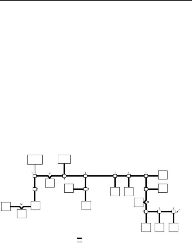
System with No Distinction between Main and Branch Lines
The diagram below shows a CompoBus/S System in which it is not necessary to distinguish between the main line and branch lines. This applies to the following conditions.
•The system operates in Long-distance Communications Mode with 4-con- ductor VCTF cable.
•The system operates in Long-distance Communications Mode with Special Flat Cable.
(The maximum length of cable is 200 m regardless of the type of communications cable.)
Communica-
tions Power Master Supply
|
|
|
Slave |
|
|
Slave |
|
|
|
Slave |
Slave |
|
|
Slave |
Slave |
|
Slave |
Slave |
Slave |
Slave |
Terminator |
||
|
|
|
|
|
Slave |
|
|
|
|
|
Slave Slave Slave |
|
|
Communications cable |
T: T-branch connection |
|
|
|
|
|
|
Power supply cable |
M: Multidrop connection |
Master |
|
The Master administers the CompoBus/S System and manages the external |
|
|
|
I/O of the Slaves. There is only one Master in a CompoBus/S System and the |
|
|
|
Master can be connected anywhere. |
|
Slaves |
|
The external I/O connected to the Slaves is processed by communicating with |
|
|
|
the Master through the CompoBus/S System. |
|
9
Loading...