


 Loading...
Cat. No. H08E-EN-01
E5CN
E5AN
E5EN
E5GN
Digital
Temperature Controllers
Getting Started Manual
E5CN/E5AN/E5EN/E5GN
Digital Temperature Controllers
Getting Started Manual
Basic Type
Revised August 2010
This manual needs the H04E+E5CN(-U) and H03E+E5EN/AN datasheet for selection and installation. (This manual is a selection from the full manual H156)
iv
Preface
The E5CN, E5CN-U, E5AN, E5EN, and E5GN are Digital Temperature Controllers. The E5CN and E5CN-U are both compact temperature controllers, with the E5CN featuring screw terminal connections, and the E5CN-U featuring socket pin connections. The E5GN can be connected using screw terminals or screwless clamp terminals. The main functions and characteristics of these Digital Temperature Controllers are as follows:
•Any of the following types of input can be used: thermocouple, platinum resistance thermometer, infrared sensor, analog voltage, or analog current.
•Either standard or heating/cooling control can be performed.
•Both auto-tuning and self-tuning are supported.
•Event inputs can be used to switch set points (multi-SP function), switch between RUN and STOP status, switch between automatic and manual operation, start/reset the simple program function, and perform other operations. (Event inputs are not applicable to the E5CN-U.)
•Heater burnout detection, heater short (HS) alarms, and heater overcurrent (OC) functions are supported. (Applicable to E5CN, E5AN, E5EN, and E5GN models with heater burnout detection function.)
•Communications are supported. (Applicable to E5CN, E5AN, E5EN, and E5GN models with communications.)
•User calibration of the sensor input is supported.
•The structure is waterproof (IP66). (Not applicable to the E5CN-U.)
•Conforms to UL, CSA, and IEC safety standards and EMC Directive.
•The PV display color can be switched to make process status easy to understand at a glance.
This manual describes the E5CN, E5CN-U, E5AN, E5EN, and E5GN for basic functions. Read this manual thoroughly and be sure you understand it before attempting to use the Digital Temperature Controller and use the Digital Temperature Controller correctly according to the information provided.
Keep this manual in a safe place for easy reference. Refer to the full manual for advanced settings:
E5CN/E5AN/E5EN/E5GN Digital Temperature Controllers User’s Manual (Cat. No. H156).
Refer to the following manual for further information on communications: E5CN/E5AN/E5EN/E5GN Digital Temperature Controllers Communications Manual Basic Type (Cat. No. H158).
Refer to the following manual for information on the Advanced Type Controllers: E5CN/E5AN/E5EN-H Digital Temperature Controllers User's Manual Advanced Type (Cat. No. H157).
Visual Aids
The following headings appear in the left column of the manual to help you locate different types of information.
Note Indicates information of particular interest for efficient and convenient operation of the product.
1,2,3... 1. Indicates lists of one sort or another, such as procedures, checklists, etc.
v
♥ OMRON, 2010
All rights reserved. No part of this publication may be reproduced, stored in a retrieval system, or transmitted, in any form, or by any means, mechanical, electronic, photocopying, recording, or otherwise, without the prior written permission of OMRON.
No patent liability is assumed with respect to the use of the information contained herein. Moreover, because OMRON is constantly striving to improve its high-quality products, the information contained in this manual is subject to change without notice. Every precaution has been taken in the preparation of this manual. Nevertheless, OMRON assumes no responsibility for errors or omissions. Neither is any liability assumed for damages resulting from the use of the information contained in this publication.
vi

Precautions for Operation
1)It takes approximately two seconds for the outputs to turn ON from after the power supply is turned ON. Due consideration must be given to this time when incorporating Temperature Controllers into a control panel or similar device.
2)Make sure that the Temperature Controller has 30 minutes or more to warm up after turning ON the power before starting actual control operations to ensure the correct temperature display.
3)When executing self-tuning, turn ON power for the load (e.g., heater) at the same time as or before supplying power to the Temperature Controller. If power is turned ON for the Temperature Controller before turning ON power for the load, self-tuning will not be performed properly and optimum control will not be achieved. When starting operation after the Temperature Controller has warmed up, turn OFF the power and then turn it ON again at the same time as turning ON power for the load. (Instead of turning the Temperature Controller OFF and ON again, switching from STOP mode to RUN mode can also be used.)
4)Avoid using the Controller in places near a radio, television set, or wireless installing. The Controller may cause radio disturbance for these devices.
Shipping Standards
The E5CN, E5CN-H, E5AN, E5AN-H, E5EN, and E5EN-H comply with Lloyd's standards. When applying the standards, the following installation and wiring requirements must be met in the application.
■ Application Conditions
1) Installation Location
The E5CN, E5CN-H, E5AN, E5AN-H, E5EN, and E5EN-H comply with installation category ENV1 and ENV2 of Lloyd's standards. Therefore, they must be installed in a location equipped with air conditioning. They must therefore be installed in a location equipped with air conditioning. They cannot be used on the bridge or decks, or in a location subject to strong vibration.
2) Wiring Conditions
Install the recommended ferrite core and wrap the line around it three turns for the applicable lines (e.g., power supply cable line and signal lines) of the models listed in the following table. (See illustrations.) Install the ferrite cores as close to the terminal block of the E5@N as possible. (As a guideline, the ferrite core should be within 10 cm of the terminal block.)
● Lines Requiring Ferrite Cores
Model |
Signal and power lines provided with ferrite cores |
|
|
E5CN, E5CN-U, or E5CN-H |
Input power supply |
|
|
E5EN, E5AN, E5EN-H, or |
Input power supply and I/O lines (control outputs (1 and 2), communications, |
E5AN-H |
event inputs (1 to 4), transfer output, and external power supply (Advanced |
|
Type models do not have an external power supply.) |
|
|
● Recommended Ferrite Core
Manufacturer |
|
Seiwa Electric Mfg. Co., Ltd. |
|
|
|
Model |
|
E04RA310190100 |
|
|
|
|
Note This part is available from Omron stock. |
|
vii
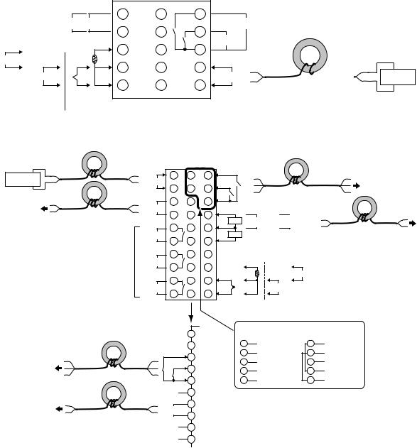
● Ferrite Core Connection Examples
1. E5CN/E5CN-H
|
|
|
|
|
|
|
|
|
|
Auxiliary outputs |
|
|
|
|
+ |
|
|
1 |
11 |
6 |
(relay outputs) |
|
|
|
|
|
|
|
|
|||
|
|
|
|
Control output 1 |
2 |
|
|
Auxiliary output 2 |
||
|
|
|
|
− |
|
|
12 |
7 |
Auxiliary |
|
|
+ |
|
|
|
A |
|
|
|
||
|
DO NOT |
DO NOT |
|
|
|
● |
||||
|
|
|
3 |
13 |
8 |
output 1 |
||||
|
|
USE |
|
USE |
|
|
|
|||
mA |
|
|
|
|
|
|
|
|
||
|
|
− |
− |
|
B |
4 |
14 |
9 |
|
|
|
− |
|
● |
|
||||||
|
|
|
|
|
|
Input power |
||||
|
V |
|
● |
|
|
|
|
|
||
|
|
|
|
|
B |
|
|
|
supply |
|
|
DO NOT |
+ |
+ |
|
5 |
15 |
10 |
|||
|
|
|
|
|||||||
|
USE |
|
|
|
|
|
|
|
||
|
|
|
|
|
|
|
|
|
|
|
|
Analog input |
|
TC/Pt universal input |
|
|
|
||||
Power supply
 AC/DC 3 turns
|
2. E5AN/E5EN/E5AN-H/E5EN-H |
|
|
|
|
|
|
|
|
|
|
|
|
||
Power |
|
3 turns |
|
1 |
21 |
11 |
Event Inputs |
|
|
|
|
|
|
||
AC/DC |
|
|
|
|
|
|
|
|
|
Connected to |
|||||
|
Input power |
|
|
|
|
|
|
|
|
||||||
|
|
|
|
|
|
|
|
|
|
|
|
||||
supply |
|
|
supply |
2 |
22 |
12 |
EV2 |
|
|
|
|
3 turns |
|
communications or |
|
|
|
|
|
EV1 |
|
|
|
event inputs 1 and 2. |
|||||||
|
|
|
|
|
|
|
|
|
|
||||||
|
|
|
+ |
3 |
23 |
13 |
|
|
Control |
|
External Power |
|
|||
Connected to |
|
|
CT1/CT2 |
Output 2 |
|
Supply |
|
|
|
||||||
|
Control output 1 |
|
|
|
|
|
|
|
|
|
|||||
control output 1. |
3 turns |
4 |
24 |
14 |
|
+ |
|
+ |
|
|
|
||||
− |
|
|
|
|
|
||||||||||
|
|
CT1 |
|
Control |
External power supply |
|
|||||||||
|
|
|
|
|
|
|
|
||||||||
|
|
|
|
|
|
|
|
Output 2 12 VDC, 20 mA |
|
|
|||||
|
|
|
|
5 |
25 |
15 |
|
|
|
3 turns |
|||||
|
|
|
|
CT2 |
− |
|
− |
|
|
||||||
|
|
|
Auxiliary output 3 |
|
|
|
|
|
|
|
|||||
|
|
|
6 |
26 |
16 |
|
DO NOT |
|
|
DO NOT |
|
|
|||
|
|
|
|
|
|
|
|
|
|
||||||
|
|
|
|
|
|
USE |
|
|
USE |
|
|
|
|||
|
|
|
|
7 |
27 |
17 |
DO NOT |
|
|
|
|
|
|
|
|
|
|
|
|
USE |
|
|
|
|
|
|
|
|
|||
|
|
|
Auxiliary output 2 |
|
|
|
|
|
|
|
|
|
|
|
|
|
|
|
|
|
|
DO NOT |
|
A |
DO NOT |
+ |
|
|
|||
|
|
|
|
8 |
28 |
18 |
|
|
|
||||||
|
|
|
|
|
|
|
|
|
|||||||
|
|
|
|
USE |
|
|
USE |
|
|
|
|
|
|||
|
|
|
|
|
|
|
|
|
|
|
mA |
|
|
||
|
|
|
|
|
|
|
− |
|
B |
− |
|
|
|
|
|
|
|
|
|
9 |
29 |
19 |
|
|
|
|
|
|
|||
|
|
|
|
|
|
|
|
|
|
− |
|
|
|||
|
|
|
Auxiliary output 1 |
|
|
|
|
|
|
V |
|
|
|
||
|
|
|
|
|
|
|
|
B |
DO NOT |
|
|||||
|
|
|
|
10 |
30 |
20 |
|
|
|
|
|
||||
|
|
|
|
+ |
|
|
+ |
|
USE |
|
|
||||
|
|
|
|
|
|
|
|
|
|
|
|
||||
|
|
|
|
|
|
|
|
|
|
|
|
|
|
||
|
|
|
|
|
|
TC/Pt universal input |
Analog input |
|
|||||||
|
|
|
|
|
|
|
|
|
|
|
Communications |
|
|||
|
|
|
|
|
21 |
|
|
RS-232C |
|
|
|
|
RS-485 |
|
|
|
|
|
|
|
|
|
|
|
|
|
|
|
|||
|
|
|
|
|
22 |
|
|
11 |
SD |
|
|
|
|
11 |
B (+) |
|
|
|
|
|
23 |
|
|
12 |
RD |
|
|
|
|
12 |
A (−) |
|
|
|
|
EV3 |
|
|
13 |
SG |
|
|
|
|
13 |
DO NOT USE |
|
|
Connected to event |
|
|
|
|
|
|
|
|
|
|||||
|
|
|
|
24 |
|
|
|
|
|
|
|
|
|
|
|
|
inputs 3 and 4. |
3 turns |
|
EV4 |
|
|
21 |
DO NOT USE |
|
21 |
B (+) |
||||
|
|
|
|
|
|
|
|
|
|
|
|
|
A (−) |
||
|
|
|
|
|
25 |
|
|
22 |
DO NOT USE |
|
22 |
||||
|
DO NOT USE |
26 |
|
Connected to |
+ |
27 |
|
Transfer output |
4 to 20 mA DC |
||
transfer output. |
|
(Load: 600 Ω max.) |
|
3 turns |
28 |
||
|
− |
|
|
|
DO NOT USE |
29 |
|
|
DO NOT USE |
30 |
|
Connected to control output 2 or external power supply.
viii

Preparations for Use
Be sure to thoroughly read and understand the manual provided with the product, and check the following points.
Timing |
Check point |
Details |
|
|
|
Purchasing the prod- |
Product appearance |
After purchase, check that the product and packaging are not dented or |
uct |
|
otherwise damaged. Damaged internal parts may prevent optimum |
|
|
control. |
|
|
|
|
Product model and speci- |
Make sure that the purchased product meets the required specifica- |
|
fications |
tions. |
|
|
|
Setting the Unit |
Product installation loca- |
Provide sufficient space around the product for heat dissipation. Do not |
|
tion |
block the vents on the product. |
|
|
|
Wiring |
Terminal wiring |
Do not subject the terminal screws to excessive stress (force) when |
|
|
tightening them. |
|
|
Make sure that there are no loose screws after tightening terminal |
|
|
screws to the specified torque of 0.74 to 0.90 N·m (see note). |
|
|
|
|
|
Be sure to confirm the polarity for each terminal before wiring the termi- |
|
|
nal block and connectors. |
|
|
|
|
Power supply inputs |
Wire the power supply inputs correctly. Incorrect wiring will result in |
|
|
damage to the internal circuits. |
|
|
|
Operating environ- |
Ambient temperature |
The ambient operating temperature for the product is −10 to 55°C (with |
ment |
|
no condensation or icing). To extend the service life of the product, |
|
|
install it in a location with an ambient temperature as low as possible. In |
|
|
locations exposed to high temperatures, if necessary, cool the products |
|
|
using a fan or other cooling method. |
|
|
|
|
Vibration and shock |
Check whether the standards related to shock and vibration are satis- |
|
|
fied at the installation environment. (Install the product in locations |
|
|
where the conductors will not be subject to vibration or shock.) |
|
|
|
|
Foreign particles |
Install the product in a location that is not subject to liquid or foreign |
|
|
particles entering the product. |
|
|
|
Note The tightening torque is 0.5 N·m for the E5CN-U and 0.43 to 0.58 N·m for the E5GN. The terminal torque is 0.5 to 0.6 N·m for auxiliary output 2 on the E5GN.
ix
Conventions Used in This Manual
Model Notation
The E5CN-@@@, E5CN-@@@U, E5AN-@@@, E5EN-@@@, and E5GN-@@@ are given as the E5CN, E5CN-U, E5AN, E5EN, and E5GN when they share functionality.
The following notation is used when specifying differences in functionality.
Notation |
Options |
|
|
E5@N-@@@B |
Two event inputs |
|
|
E5@N-@@@03 |
RS-485 communications |
|
|
E5@N-@@H |
One of HB, HS, and heater overcurrent detection |
|
|
E5@N-@@HH |
Two of HB, HS, and heater overcurrent detection (See note 1.) |
|
|
E5@N-@Q |
Control output 2 (voltage output) (See note 1.) |
|
|
E5@N-@@P |
External power supply to ES1B (See note 1.) |
|
|
E5@N-@@@01 |
RS-232C communications (See note 2.) |
|
|
E5@N-@@F |
Transfer output (See note 3.) |
|
|
Note: (1) Excluding the E5GN.
(2)Excluding the E5CN.
(3)The E5AN and E5EN only.
Meanings of Abbreviations
The following abbreviations are used in parameter names, figures and in text explanations. These abbreviations mean the following:
Symbol |
Term |
|
|
PV |
Process value |
|
|
SP |
Set point |
|
|
SV |
Set value |
|
|
AT |
Auto-tuning |
|
|
ST |
Self-tuning |
|
|
HB |
Heater burnout |
|
|
HS |
Heater short (See note 1.) |
|
|
OC |
Heater overcurrent |
|
|
LBA |
Loop burnout alarm |
|
|
EU |
Engineering unit (See note 2.) |
|
|
Note: (1) A heater short indicates that the heater remains ON even when the control output from the Temperature Controller is OFF because the SSR has failed or for any other reason.
(2)“EU” stands for Engineering Unit. EU is used as the minimum unit for engineering units such as °C,
m, and g. The size of EU varies according to the input type.
For example, when the input temperature setting range is –200 to +1300°C, 1 EU is 1°C, and when the input temperature setting range is –20.0 to +500.0°C, 1 EU is 0.1°C.
For analog inputs, the size of EU varies according to the decimal point position of the scaling setting, and 1 EU becomes the minimum scaling unit.
x
TABLE OF CONTENTS
SECTION 1 |
|
|
Introduction. . . . . . . . . . . . . . . . . . . . . . . . . . . . . . . . . . . . . . . |
1 |
|
1-1 |
Names of Parts. . . . . . . . . . . . . . . . . . . . . . . . . . . . . . . . . . . . . . . . . . . . . . . . . . . . . . . . . . . . |
2 |
1-2 |
I/O Configuration and Main Functions . . . . . . . . . . . . . . . . . . . . . . . . . . . . . . . . . . . . . . . . . |
6 |
1-3 |
Setting Level Configuration and Key Operations . . . . . . . . . . . . . . . . . . . . . . . . . . . . . . . . . |
12 |
1-4 |
Communications Function. . . . . . . . . . . . . . . . . . . . . . . . . . . . . . . . . . . . . . . . . . . . . . . . . . . |
15 |
1-5 |
Insulation Block Diagrams . . . . . . . . . . . . . . . . . . . . . . . . . . . . . . . . . . . . . . . . . . . . . . . . . . |
17 |
SECTION 2 |
|
|
Preparations . . . . . . . . . . . . . . . . . . . . . . . . . . . . . . . . . . . . . . |
19 |
|
2-1 |
Installation . . . . . . . . . . . . . . . . . . . . . . . . . . . . . . . . . . . . . . . . . . . . . . . . . . . . . . . . . . . . . . . |
20 |
2-2 |
Using the Support Software Port . . . . . . . . . . . . . . . . . . . . . . . . . . . . . . . . . . . . . . . . . . . . . . |
26 |
SECTION 3 |
|
|
Basic Operation. . . . . . . . . . . . . . . . . . . . . . . . . . . . . . . . . . . . |
29 |
|
3-1 |
Initial Setting Examples. . . . . . . . . . . . . . . . . . . . . . . . . . . . . . . . . . . . . . . . . . . . . . . . . . . . . |
30 |
3-2 |
Setting the Input Type . . . . . . . . . . . . . . . . . . . . . . . . . . . . . . . . . . . . . . . . . . . . . . . . . . . . . . |
32 |
3-3 |
Selecting the Temperature Unit . . . . . . . . . . . . . . . . . . . . . . . . . . . . . . . . . . . . . . . . . . . . . . . |
34 |
3-4 |
Selecting PID Control or ON/OFF Control . . . . . . . . . . . . . . . . . . . . . . . . . . . . . . . . . . . . . . |
34 |
3-5 |
Setting Output Specifications . . . . . . . . . . . . . . . . . . . . . . . . . . . . . . . . . . . . . . . . . . . . . . . . |
34 |
3-6 |
Setting the Set Point (SP) . . . . . . . . . . . . . . . . . . . . . . . . . . . . . . . . . . . . . . . . . . . . . . . . . . . |
39 |
3-7 |
Using ON/OFF Control . . . . . . . . . . . . . . . . . . . . . . . . . . . . . . . . . . . . . . . . . . . . . . . . . . . . . |
40 |
3-8 |
Determining PID Constants (AT, ST, Manual Setup) . . . . . . . . . . . . . . . . . . . . . . . . . . . . . . |
42 |
3-9 |
Alarm Outputs . . . . . . . . . . . . . . . . . . . . . . . . . . . . . . . . . . . . . . . . . . . . . . . . . . . . . . . . . . . . |
49 |
3-10 |
Using Heater Burnout, Heater Short, and Heater Overcurrent Alarms . . . . . . . . . . . . . . . . . |
53 |
3-11 |
Setting the No. 3 Display. . . . . . . . . . . . . . . . . . . . . . . . . . . . . . . . . . . . . . . . . . . . . . . . . . . . |
61 |
SECTION 4 |
|
|
Applications Operations. . . . . . . . . . . . . . . . . . . . . . . . . . . . . |
63 |
|
4-1 |
Shifting Input Values . . . . . . . . . . . . . . . . . . . . . . . . . . . . . . . . . . . . . . . . . . . . . . . . . . . . . . . |
64 |
4-2 |
Alarm Hysteresis . . . . . . . . . . . . . . . . . . . . . . . . . . . . . . . . . . . . . . . . . . . . . . . . . . . . . . . . . . |
68 |
4-3 |
Setting Scaling Upper and Lower Limits for Analog Inputs. . . . . . . . . . . . . . . . . . . . . . . . . |
69 |
4-4 |
Executing Heating/Cooling Control . . . . . . . . . . . . . . . . . . . . . . . . . . . . . . . . . . . . . . . . . . . |
70 |
4-5 |
Using Event Inputs . . . . . . . . . . . . . . . . . . . . . . . . . . . . . . . . . . . . . . . . . . . . . . . . . . . . . . . . |
74 |
4-6 |
Setting the SP Upper and Lower Limit Values . . . . . . . . . . . . . . . . . . . . . . . . . . . . . . . . . . . |
79 |
4-7 |
Using the SP Ramp Function to Limit the SP Change Rate . . . . . . . . . . . . . . . . . . . . . . . . . |
81 |
Index. . . . . . . . . . . . . . . . . . . . . . . . . . . . . . . . . . . . . . . . . . . . . |
85 |
|
Revision History . . . . . . . . . . . . . . . . . . . . . . . . . . . . . . . . . . . |
88 |
|
xi

About this Manual:
This manual describes the E5CN/CN-U/AN/EN Digital Temperature Controllers and includes the sections described below.
Please read this manual carefully and be sure you understand the information provided before attempting to set up or operate an E5CN/CN-U/AN/EN Digital Temperature Controller.
• Overview
Section 1 introduces the features, components, and main specifications of the E5CN/CN-U/AN/EN/ GN Digital Temperature Controllers.
• Setup
Section 2 describes the work required to prepare the E5CN/CN-U/AN/EN/GN Digital Temperature Controllers for operation, including installation and wiring.
• Basic Operations
Section 3 describes the basic operation of the E5CN/CN-U/AN/EN/GN Digital Temperature Controllers, including key operations to set parameters and descriptions of display elements based on specific control examples.
Section 5 describes the individual parameters used to setup, control, and monitor operation.
• Operations for Applications
Section 4 describes scaling, the SP ramp function, and other special functions that can be used to make the most of the basic functionality of the E5CN/CN-U/AN/EN/GN Digital Temperature Controllers.
!WARNING Failure to read and understand the information provided in this manual may result in personal injury or death, damage to the product, or product failure. Please read each section in its entirety and be sure you understand the information provided in the section and related sections before attempting any of the procedures or operations given.
xii
SECTION 1
Introduction
This section introduces the features, components, and main specifications of the E5GN, E5CN, E5EN and E5AN digital temperature controllers.
1-1 |
Names of Parts . . . . . . . . . . . . . . . . . . . . . . . . . . . . . . . . . . . . . . . . . . . . . . . . |
2 |
|
|
1-1-1 |
Front Panel . . . . . . . . . . . . . . . . . . . . . . . . . . . . . . . . . . . . . . . . . . . . |
2 |
|
1-1-2 |
Explanation of Indicators . . . . . . . . . . . . . . . . . . . . . . . . . . . . . . . . . |
4 |
|
1-1-3 |
Using the Keys . . . . . . . . . . . . . . . . . . . . . . . . . . . . . . . . . . . . . . . . . |
5 |
1-2 I/O Configuration and Main Functions. . . . . . . . . . . . . . . . . . . . . . . . . . . . . . |
6 |
||
|
1-2-1 |
I/O Configuration . . . . . . . . . . . . . . . . . . . . . . . . . . . . . . . . . . . . . . . |
6 |
|
1-2-2 |
Main Functions . . . . . . . . . . . . . . . . . . . . . . . . . . . . . . . . . . . . . . . . . |
10 |
1-3 |
Setting Level Configuration and Key Operations. . . . . . . . . . . . . . . . . . . . . . |
12 |
|
|
1-3-1 |
Selecting Parameters. . . . . . . . . . . . . . . . . . . . . . . . . . . . . . . . . . . . . |
14 |
|
1-3-2 |
Saving Settings . . . . . . . . . . . . . . . . . . . . . . . . . . . . . . . . . . . . . . . . . |
15 |
1-4 |
Communications Function . . . . . . . . . . . . . . . . . . . . . . . . . . . . . . . . . . . . . . . |
15 |
|
1-5 |
Insulation Block Diagrams . . . . . . . . . . . . . . . . . . . . . . . . . . . . . . . . . . . . . . . |
17 |
|
1

Names of Parts |
Section 1-1 |
1-1 Names of Parts
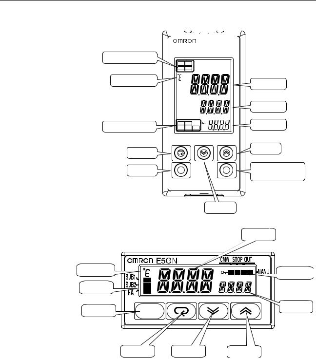
1-1-1 Front Panel
E5CN/CN-U |
The front panel is the same for the E5CN and E5CN-U. |
Temperature unit
No. 1 display
Operation indicators
No. 2 display
Up Key
Level Key
Mode Key |
Down Key |
E5AN
Temperature unit
|
SUB1 |
|
PV |
|
SUB2 |
|
|
|
|
|
|
Operation indicators |
SUB3 |
|
|
HA |
|
|
|
|
|
|
|
|
|
|
SV |
|
OUT1 |
STOP |
MV |
|
OUT2 |
CMW |
MANU |
Function Key/ |
PF |
Auto/Manual Key |
A/M |
E5AN
Level Key |
Mode Key |
No.1 display
No. 2 display
No. 3 display
Up Key
Down Key
2
|
Names of Parts |
|
|
|
|
|
|
|
Section 1-1 |
E5EN |
|
|
|
|
|
|
|
|
|
|
|
|
|
|
|
|
|
|
|
|
|
|
|
|
|
|
|
|
|
Operation indicators
Temperature unit
Operation indicators
Mode Key
Level Key
SUB1 |
SUB2 |
|
|
|
HA |
SUB3 |
|
|
|
|
|
PV |
|
|
|
|
|
No.1 display |
|
|
|
SV |
No.2 display |
|
|
|
|
||
OUT1 |
STOP |
MV |
No.3 display |
|
OUT2 |
CMW |
|||
MANU |
|
Up Key
PF |
Function Key/ |
A/M |
Auto/Manual Key |
|
E5EN
Down Key
E5GN
No. 1 display
Temperature |
Operation |
|
unit |
||
indicators |
||
|
Operation indicators
No. 2 display
Level Key
Mode Key |
Down Key |
Up Key |
3

Names of Parts Section 1-1
1-1-2 Explanation of Indicators
No. 1 Display Displays the process value or parameter name.
Lights for approximately one second during startup.
No. 2 Display
No. 3 Display
(E5AN/EN Only)
Operation Indicators
1,2,3...
Temperature Unit
Displays the set point, parameter operation read value, or the variable input value.
Lights for approximately one second during startup.
The set point will flash during autotuning.
Displays MV, soak time remaining, or multi SP.
Lights for approximately one second during startup.
A 2-level display is set when shipped from the factory.
A 3-level display is activated if parameters are initialized.
1.SUB1 (Sub 1)
Lights when the function set for the Auxiliary Output 1 Assignment parameter is ON.
SUB2 (Sub 2)
Lights when the function set for the Auxiliary Output 2 Assignment parameter is ON.
SUB3 (Sub 3) (E5AN/EN Only)
Lights when the function set for the Auxiliary Output 3 Assignment parameter is ON.
2.HA (Heater Burnout, Heater Short Alarm, Heater Overcurrent Detection Output Display)
Lights when a heater burnout, heater short alarm, or heater overcurrent occurs.
3.OUT1 (Control Output 1)
Lights when the control output function assigned to control output 1 turns ON. For a current output, however, OFF for a 0% output only.
OUT2 (Control Output 2) (Excluding the E5GN)
Lights when the control output function assigned to control output 2 turns ON. For a current output, however, OFF for a 0% output only.
4.STOP
Lights when operation is stopped.
During operation, this indicator lights when operation is stopped by an event or by key input using the RUN/STOP function.
5.CMW (Communications Writing)
Lights when communications writing is enabled and is not lit when it is disabled.
6.MANU (Manual Mode)
Lights when the auto/manual mode is set to manual mode.
7.
 (Key)
(Key)
Lights when settings change protect is ON (i.e., when the U and D Keys are disabled by protected status.)
The temperature unit is displayed when parameters are set to display a temperature. The display is determined by the currently set value of the Temperature Unit parameter. °c indicates °C and °f indicates °F.
This indicator flashes during ST operation. It is OFF on models with linear inputs.
4

Names of Parts |
Section 1-1 |
1-1-3 Using the Keys
This section describes the basic functions of the front panel keys.
PF (Function (Auto/
Manual)) Key
(E5AN/EN Only)
This is a function key. When it is pressed for at least 1 second, the function set in the PF Setting parameter will operate.
Example: When A-M (auto/manual) is selected in the PF Setting parameter (initial value: A-M), the key operates as an auto/manual switch, switching between Auto Mode and Manual Mode. If the key is pressed for more than 1 second (regardless of key release timing), the mode will switch.
O Key |
Press this key to move between setting levels. The setting level is selected in |
|
the following order: operation level: adjustment level, initial setting level, com- |
|
munications setting level. |
M Key |
Press this key to change parameters within a setting level. |
|
The parameters can be reversed by holding down the key (moving one per |
|
second in reverse order). |
U Key |
Each press of this key increments the value displayed on the No. 2 display or |
|
advances the setting. Holding the key down speeds up the incrementation. |
D Key |
Each press of this key decrements values displayed on the No. 2 display or |
|
reverses the setting. Holding the key down speeds up the incrementation. |
O + M Keys
O + U Keys
O + D Keys
Press these keys to change to the protect level. For details on operations involving holding these keys down simultaneously, refer to 1-3 Setting Level Configuration and Key Operations.
To restrict set value changes (in order to prevent accidental or incorrect operations), these key operations require simultaneously pressing the O key along with U or D key. This applies only to the parameter for the password to move to protect level.
5

I/O Configuration and Main Functions |
Section 1-2 |
1-2 I/O Configuration and Main Functions
1-2-1 I/O Configuration
E5CN
|
|
|
|
Control |
|
|
|
|
|
|
|
|
|
|
|
|
|
|
|
|
Temperature input |
|
|
|
Control output |
|
|
|
|
|
|
|
|
|
|
Control output 1 |
|
||
|
|
|
section |
|
(heating) |
|
|
|
|
|
|
|
|
|
|
|
|||
|
or analog input |
|
|
|
|
|
|
|
|
|
|
|
|
|
|
||||
|
|
|
|
|
|
|
|
|
|
|
|
|
|||||||
|
|
|
|
|
|
|
|
|
|
|
|
|
|
|
|
|
|
|
|
|
|
|
|
|
|
|
|
|
|
|
|
|
|
|
|
|
|
|
|
|
|
|
|
|
|
|
|
|
|
|
|
|
|
|
|
|
|
|
|
|
|
|
|
|
|
Control output |
|
|
|
|
|
|
|
|
|
|
Control output 2 |
|
|
|
|
|
|
|
|
(cooling) |
|
|
|
|
Heating/cooling |
|
|
|
|
(See note.) |
|||
|
|
|
|
|
|
|
|
|
|
|
|
|
|
|
|||||
|
|
|
|
|
|
|
|
|
|
|
|
|
|
|
|
|
|
||
|
|
|
|
|
|
|
|
|
|
|
|
|
|
|
|
|
|
||
|
|
|
|
|
|
|
|
|
|
|
|
|
|
|
|
|
|
|
|
|
|
|
|
|
|
|
|
|
|
|
|
|
|
|
|
|
|
External power |
(See note.) |
|
|
|
|
|
|
|
|
|
|
|
|
|
|
|
|
|
|
supply for ES1B |
|
|
|
|
|
|
|
Alarm 3 |
|
|
|
|
|
|
|
|
|
|
|
||
|
|
|
|
|
|
|
|
|
|
|
|
|
|
|
|
|
|
||
|
CT1 input |
|
|
|
|
|
|
|
|
|
|
|
|
|
|
|
|
|
|
|
|
|
|
|
|
|
|
|
|
|
|
|
|
|
|
|
|
|
|
|
|
|
|
|
|
Alarm 2 |
|
|
|
|
|
|
|
|
|
|
Auxiliary output 2 |
|
|
|
|
|
|
|
|
|
|
|
|
|
|
|
|
|
|
|
|
|
|
|
|
|
|
|
|
|
|
|
|
|
|
|
|
|
|
|
|
|
|
|
|
|
|
|
|
Alarm 1 |
|
|
|
|
|
|
|
|
|
|
|
|
|
|
CT2 input |
|
|
|
|
|
|
|
|
|
|
|
|
|
|
|
|
||
|
|
|
|
|
|
|
|
|
|
|
|
|
|
|
|
|
|
|
|
|
|
|
|
|
|
|
|
|
|
|
|
|
|
|
|
|
|
|
|
|
|
|
|
|
|
HB alarm |
|
|
|
|
|
|
|
|
|
|
|
|
|
|
|
|
|
|
|
|
|
|
|
|
|
|
|
|
|
|
|
|
|
|
|
|
|
|
|
|
|
|
|
|
|
|
|
|
|
|
|
|
|
|
|
|
|
|
|
|
|
|
|
|
|
|
|
|
|
|
|
|
|
|
|
|
|
|
|
HS alarm |
|
|
|
|
|
|
|
|
|
Auxiliary output 1 |
|
||
|
|
|
|
|
|
|
|
|
|
|
|
|
|
|
|
||||
|
Event inputs |
|
|
|
|
|
|
|
|
|
|
|
|
|
|
|
|
|
|
|
|
|
|
|
|
|
|
|
|
|
|
|
|
|
|
|
|
|
|
|
2 channels |
|
|
|
|
|
|
|
|
|
|
|
|
|
|
|
|
|
|
|
|
|
|
OC alarm |
|
|
|
|
|
|
|
|
|
|
|
|
|||
|
|
|
|
|
|
|
|
|
|
|
|
|
|
|
|
|
|
||
|
|
|
|
|
|
|
|
|
|
|
|
|
|
|
|
|
|
||
|
|
|
|
|
|
|
|
|
|
|
|
|
|
|
|
|
|
|
|
|
|
|
|
|
|
|
|
|
|
|
|
|
|
|
|
|
|
|
|
|
|
|
|
|
|
Input error |
|
|
|
|
|
|
|
|
|
|
|
|
|
|
|
|
|
|
|
|
|
|
|
|
|
|
|
|
|
|
|
||
|
|
|
|
|
|
|
|
|
|
|
|
|
|
|
|
|
|
|
|
|
|
|
|
|
|
|
|
|
|
|
|
|
|
|
|
|
|
|
|
|
|
|
|
|
|
Program end |
|
|
|
|
|
|
|
|
|
|
|
|
|
|
|
|
|
|
|
output |
|
|
|
|
|
|
|
|
Note: |
|
|||
|
|
|
|
|
|
|
|
|
|
|
|
|
|
|
|
Press one of these keys, |
|||
|
|
|
|
|
|
Communications |
|
|
|
|
|
|
|||||||
|
|
|
|
|
|
|
|
|
|
|
|
|
|
depending on the model. |
|||||
|
|
|
|
|
|
function |
|
|
|
|
|
|
|
|
|||||
|
|
|
|
|
|
|
|
|
|
|
|
|
|
|
|
|
|
||
|
|
|
|
|
|
|
|
|
|
|
|
|
|
|
|
|
|
|
|
|
|
|
|
|
|
|
|
|
|
|
|
|
|
|
|
|
|
|
|
Note Functions can be assigned individually for each output by changing the set values for the Control Output 1 Assignment, the Control Output 2 Assignment, the Auxiliary Output 1 Assignment, and the Auxiliary Output 2 Assignment parameters in the advanced function setting level.
6

I/O Configuration and Main Functions |
Section 1-2 |
E5CN-U
Temperature input or analog input
Control |
|
Control output |
|
|
|
|
|
Control output 1 |
|
|
|
|
|
|
|
|
|||
section |
|
(heating) |
|
|
|
|
|
|
|
|
|
|
|
|
|
|
|||
|
|
|
|
|
|
|
|
|
|
|
|
|
|
|
|
|
|
|
|
|
|
Control output |
|
|
|
|
|
|
|
|
|
(cooling) |
|
Heating/ |
|||||
|
|
|
|
cooling |
|
|
|
||
|
|
Alarm 3 |
|
|
|
|
|
Auxiliary output 2 |
|
|
|
|
|
|
|
|
|
||
|
|
|
|
|
|
|
|
|
|
Standard
Alarm 2
Alarm 1


 Auxiliary output 1
Input error
Program end output
Note Functions can be assigned individually for each output by changing the set values for the Control Output 1 Assignment, the Auxiliary Output 1 Assignment, and the Auxiliary Output 2 Assignment parameters in the advanced function setting level.
7
I/O Configuration and Main Functions |
Section 1-2 |
E5AN/EN
Temperature input or analog input
CT1 input
CT2 input
Event inputs 1 and 2 (2 channels)
Control |
|
Control output |
section |
|
|
|
(heating) |
|
|
|
Control output |
|
|
|
|
|
(cooling) |
Alarm 3
Alarm 2
Alarm 1
HB alarm
HS alarm
OC alarm
Input error
Program end output
Communications function
|
|
|
|
|
|
|
|
|
|
|
|
|
|
|
|
|
|
|
|
|
|
|
|
|
|
|
|
|
|
|
|
|
|
|
|
|
|
|
|
|
|
|
|
|
|
|
|
|
|
|
|
|
|
|
|
|
|
Control output 1 |
|
|
|
|
|
|
|
|
|
|
|
|
|
|
|
|
|
|
|
|
|
|
|
|
|
|
|
|
|
|
|
|
|
|
|
|
|
|
|
|
|
|
|
|
|
|
|
|
|
|
|
|
|
|
|
|
|
|
|
|
|
|
|
|
|
|
|
|
|
|
|
|
|
|
|
|
|
|
|
|
|
|
|
|
|
|
|
|
|
|
|
|
|
|
|
|
|
|
|
|
|
|
|
|
|
|
|
|
|
|
|
|
|
|
|
|
|
|
|
Control output 2 |
(See note.) |
|
|
Heating/cooling |
|
|
|
||||||||||||||||||||||||
|
|
|
|
|
|||||||||||||||||||||||||
|
|
|
|
||||||||||||||||||||||||||
|
|
|
|
|
|
|
|
|
|
|
|
|
|
|
|
|
|
|
|
|
|
|
|
|
|
|
|
External power |
(See note.) |
|
|
|
|
|
|
|
|
|
|
|
|
|
|
|
|
|
|
|
|
|
|
|
|
|
|
|
|
supply for ES1B |
|
|
|
|
|
|
|
|
|
|
|
|
|
|
|
|
|
|
|
|
|
|
|
|
|
|
|
|
|
|
|
|
|
|
|
|
|
|
|
|
|
|
|
|
|
|
|
|
|
|
|
|
|
|
|
|
|
|
|
|
|
|
|
|
|
|
|
|
|
|
|
|
|
|
|
|
|
|
|
|
|
|
|
|
|
|
|
|
|
|
|

 Alarm output 3
 Alarm output 2


 Alarm output 1
Note:
Press one of these keys, depending on the model.
Note Functions can be assigned individually to each output by changing the set values for the Control Output 1 Assignment, Control Output 2 Assignment, Auxiliary Output 1 Assignment, Auxiliary Output 2 Assignment, and Auxiliary Output 3 Assignment parameters in the advanced function setting level.
8
I/O Configuration and Main Functions |
|
Section 1-2 |
||
E5GN |
|
|
|
|
Temperature input |
Control |
Control output |
Control output 1 |
|
or analog input |
section |
(heating) |
||
|
||||
|
|
Control output |
|
|
|
|
(cooling) |
Heating/ |
|
|
|
|
cooling |
|
|
|
Alarm 1 |
Auxiliary output 1 |
|
|
|
Standard |
||
|
|
|
||
CT1 input |
|
HB alarm |
|
|
|
|
|
||
HS alarm
OC alarm
Input error
Event inputs 2 channels
Alarm 2 |
|
|
|
|
|
|
|
|
|
|
|
|
|
|
|
|
|
|
Auxiliary output 2 |
Alarm 3
Program end output
Communications function
Note Functions can be assigned individually for each output by changing the set values for the Control Output 1 Assignment, the Auxiliary Output 1 Assignment, and the Auxiliary Output 2 Assignment parameters in the advanced function setting level.
9

I/O Configuration and Main Functions Section 1-2
1-2-2 Main Functions
This section introduces the main E5CN/CN-U/AN/EN/GN functions. For details on particular functions and how to use them, refer to SECTION 3 Basic Operation and following sections.
Input Sensor Types |
• The following input sensors can be connected for temperature input |
||||||||||||
|
(i.e., E5_N-@@@@T): |
|
|
|
|
||||||||
|
Thermocouple: |
|
|
|
|
K, J, T, E, L, U, N, R, S, B, W, PLII |
|||||||
|
Infrared temperature sensor: |
|
ES1B |
|
|||||||||
|
|
|
|
|
|
|
|
|
|
|
10 to 70°C, 60 to 120°C, 115 to 165°C, |
||
|
|
|
|
|
|
|
|
|
|
|
140 to 260°C |
|
|
|
Platinum resistance thermometer: Pt100, JPt100 |
|
|||||||||||
|
Analog input: |
|
|
|
|
0 to 50 mV |
|
||||||
|
• Inputs with the following specifications can be connected for analog input |
||||||||||||
|
(i.e., E5_N-@@@@L): |
|
|
|
|
||||||||
|
Current input: 4 to 20 mA DC, 0 to 20 mA DC |
|
|||||||||||
|
Voltage input: 1 to 5 VDC, 0 to 5 V DC, 0 to 10 V DC |
||||||||||||
Control Outputs |
• A control output can be a relay, voltage (for driving SSR), or current out- |
||||||||||||
|
put, depending on the model. |
|
|
|
|
||||||||
|
• Long-life relay outputs (see note) use semiconductors for switching when |
||||||||||||
|
closing and opening the circuit, thereby reducing chattering and arcing |
||||||||||||
|
and improving durability. However, if high levels of noise or surge are |
||||||||||||
|
imposed between the output terminals, short-circuit faults may occasion- |
||||||||||||
|
ally occur. If the output becomes permanently shorted, there is the danger |
||||||||||||
|
of fire due to overheating of the heater. Design safety into the system, |
||||||||||||
|
including measures to prevent excessive temperature rise and spreading |
||||||||||||
|
of fire. Take countermeasures such as installing a surge absorber. As an |
||||||||||||
|
additional safety measure, provide error detection in the control loop. |
||||||||||||
|
(Use the Loop Burnout Alarm (LBA) and HS alarm that are provided for |
||||||||||||
|
the E5@N.) |
|
|
|
|
|
|
|
|||||
|
|
|
|
|
|
|
Varistor |
|
|
|
|
||
|
Long-life |
|
|
|
|
|
|
|
|
||||
|
relay output |
|
|
|
|
|
|
|
|
|
|
||
|
|
|
|
|
|
|
|
|
|
|
|||
|
|
|
|
|
|
|
|
|
|
|
|
|
|
|
1 |
|
|
|
|
Inductive |
|
|
|
|
|||
|
|
|
|
|
load |
|
|
|
|
||||
|
|
|
|
|
|
|
Varistor |
|
|
|
|
||
|
2 |
|
|
|
|
|
|
|
|
|
|||
|
|
|
|
|
|
|
|
|
|
||||
|
|
|
|
|
|
|
|
|
|
|
|||
|
Select a surge absorber that satisfies the following conditions. |
||||||||||||
|
|
|
|
|
|
|
|
|
|
|
|
|
|
|
Voltage used |
|
Varistor voltage |
|
Surge resistance |
||||||||
|
|
|
|
|
|
|
|
|
|
|
|
|
|
|
100 to 120 VAC |
240 to 270 V |
|
|
1,000 A min. |
||||||||
|
|
|
|
|
|
|
|
|
|
|
|
|
|
|
200 to 240 VAC |
440 to 470 V |
|
|
|
|
|||||||
|
|
|
|
|
|
|
|
|
|
|
|
|
|
|
• Always connect an AC load to a long-life relay output (see note). The out- |
||||||||||||
|
put will not turn OFF if a DC load is connected. |
|
|||||||||||
Note |
Long-life relay outputs are not supported for the E5GN. |
|
|||||||||||
Alarms |
• Set the alarm type and alarm value or the alarm value upper and lower |
||||||||||||
|
limits. |
|
|
|
|
|
|
|
|||||
• If necessary, a more comprehensive alarm function can be achieved by setting a standby sequence, alarm hysteresis, auxiliary output close in alarm/open in alarm, alarm latch, alarm ON delay, and alarm OFF delay.
• If the Input Error Output parameter is set to ON, the output assigned to alarm 1 function will turn ON when an input error occurs.
10

|
I/O Configuration and Main Functions |
Section 1-2 |
|
Control Adjustment |
• Optimum PID constants can be set easily by performing AT (auto-tuning) |
||
|
|
or ST (self-tuning). |
|
Event Inputs |
• With the E53-CN@B@N2 for the E5CN or the E5AN/EN-@M@-500-N with |
||
the E53-AKB for the E5AN/EN, the following functions can be executed using event inputs: switching set points (multi-SP, 4 points max.), switching RUN/STOP, switching between automatic and manual operation, starting/resetting the program, inverting direct/reverse operation, 100% AT execute/cancel, 40% AT execute/cancel, setting change enable/disable, and canceling the alarm latch.
Heater Burnout, HS Alarm,
and Heater Overcurrent
•With the E53-CN@H@N2 or E53-CN@HH@N2 for the E5CN, or the E5AN/EN-@@H@-500-N or E5AN/EN-@@HH@-500-N, the heater burnout detection function, HS alarm function, and heater overcurrent detection function can be used.
Communications
Functions
Note
External Power Supply for ES1B
Note
•Communications functions utilizing CompoWay/F (See note 1.), SYSWAY (See note 2.), or Modbus (See note 3.) can be used.
RS-485 Interface
Use the E53-CN@03N2 for the E5CN or the E53-EN03 for the E5AN/ EN.
RS-232C Interface
Use the E53-EN01 for the E5AN/EN.
(1)CompoWay/F is an integrated general-purpose serial communications protocol developed by OMRON. It uses commands compliant with the well-established FINS, together with a consistent frame format on OMRON Programmable Controllers to facilitate communications between personal computers and components.
(2)SYSWAY communications do not support alarm 3.
(3)Modbus is a communications control method conforming to the RTU Mode of Modbus Protocol. Modbus is a registered trademark of Schneider Electric.
(4)The E5CN and E5CN-U do not support the RS-232C interface.
The E5AN-@P@-N or E5EN-@P@-N with the E53-CN@P@N2 can be used as the power supply for ES1B Infrared Temperature Sensors.
The E5GN does not provide a power supply for an ES1B Infrared Temperature Sensor.
Transfer Output |
A transfer output for 4 to 20 mA can be used with the E5AN/E5EN-@@F. |
|
For E5@N-C@@ models (models without “F” in the model number), the cur- |
|
rent output can be used as a simple transfer output. |
11

Setting Level Configuration and Key Operations |
Section 1-3 |
1-3 Setting Level Configuration and Key Operations
Parameters are divided into groups, each called a level. Each of the set values (setting items) in these levels is called a parameter. The parameters on the E5CN/CN-U/AN/EN/GN are divided into the following 9 levels.
When the power is turned ON, all of the display lights for approximately one second.
Power ON
Start in manual mode.
Manual mode
Start in automatic mode.
Press the O Key or the |
|
|
|
|
|
|
|
|
PF Key for at least 1 s. |
|
|
|
|
|
|
|
|
(See note 4.) |
Operation |
|
Adjustment |
|
|
Press the |
||
|
|
|
|
|
O+ M |
|||
|
|
Level |
|
Level |
Press the |
|
Keys for at |
|
|
|
Press the |
|
|
O+ M |
|
least 1 s. |
|
a-m |
|
|
Keys for at |
|
|
|||
O |
Key less than 1 s. |
least 3 s. |
c |
25 |
||||
|
(Display |
|||||||
|
|
|
|
|
|
will flash |
|
100 |
|
|
|
|
|
|
after 1st |
|
|
|
|
|
|
|
PF Key |
|
|
|
|
Press the O Key |
|
|
|
second.) |
|
|
|
(See |
PF Key |
Monitor/Setting |
(See note 5.) |
|
|
|
||
for at least 3 s while |
|
|
|
|
||||
note |
a-m is displayed. |
(See note 5.) |
Item Level |
|
|
|
|
|
3.) |
(a-m will flash after |
|
|
|
|
|
|
|
1st second.) |
|
|
|
|
|
|
|
|
|
(See note 4.) |
|
|
|
Press the O Key for at |
|
|
|
|
Press the PF Key |
|
|
|
|
|
|
|
Manual |
(See |
|
|
least 3 s. (Display will flash |
|
|
||
for at least 1 s. |
c |
25 |
after 1st second.) |
|
|
|
||
Control Level |
Press the |
note 1.) |
|
100 |
|
|
|
|
|
|
|
|
|
|
Protect Level |
||
|
O Key for |
|
|
|
|
|
|
|
|
at least 1 s. |
|
|
|
|
|
|
|
|
|
|
|
Note The time taken to move |
|
|
|
Communica- |
to the protect level can |
|
Initial Setting |
|
be adjusted by chang- |
|
Control stops. |
|
tions Setting |
||
Level |
|
ing the "Move to pro- |
||
|
|
Press the |
Level |
tect level time" setting. |
|
|
O Key for less than 1 s. |
|
|
|
Press the O Key |
Input password while |
|
|
|
amoV is displayed. (Set |
|
||
|
for at least 1 s. |
|
||
|
value −169) |
|
|
|
|
Advanced Function |
|
|
|
|
Setting Level |
|
|
|
|
|
|
Control in progress |
|
|
Input password. |
Control stopped |
||
|
|
|
||
Note: Not described in this manual. |
|
|
Not displayed for some models |
|
Calibration Level |
(See |
Level change |
||
Please refer to H156 |
note 2.) |
|||
|
||||
Note (1) You can return to the operation level by executing a software reset.
(2)You cannot move to other levels by operating the keys on the front panel from the calibration level. You must turn OFF the power supply.
(3)From the manual control level, key operations can be used to move to the operation level only.
Level |
Control in progress |
Control stopped |
|
|
|
Protect level |
Can be set. |
--- |
|
|
|
Operation level |
Can be set. |
--- |
|
|
|
Adjustment level |
Can be set. |
--- |
|
|
|
Manual control level |
Can be set. |
--- |
|
|
|
Monitor/setting item level |
Can be set. |
--- |
|
|
|
Initial setting level |
--- |
Can be set. |
|
|
|
12

|
Setting Level Configuration and Key Operations |
|
Section 1-3 |
||
|
|
|
|
|
|
|
|
|
Level |
Control in progress |
Control stopped |
|
|
|
|
|
|
|
|
|
Advanced function setting level |
--- |
Can be set. |
|
|
|
|
|
|
|
|
|
Calibration level |
--- |
Can be set. |
|
|
|
|
|
|
|
|
|
Communications setting level |
--- |
Can be set. |
|
|
|
|
|
|
|
|
|
Of these levels, the initial setting level, communications setting level, |
||
|
|
|
advanced function setting level, and calibration level can be used only |
||
|
|
|
when control is stopped. Control outputs are stopped when any of |
||
|
|
|
these four levels is selected. |
|
|
|
|
(4) When the PF Setting is set to A-M in models with a PF Key (E5AN/EN) |
|||
|
|
(5) When the PF Setting is set to PFDP in models with a PF Key (E5AN/EN) |
|||
Protect Level |
• To switch to the protect level from the operation level, the adjustment |
||||
|
|
level, or the monitor/setting item level, simultaneously hold down the O |
|||
|
|
and M Keys for at least 3 seconds. (See note.) This level is for preventing |
|||
|
|
unwanted or accidental modification of parameters. Protected levels will |
|||
|
|
not be displayed, and so the parameters in that level cannot be modified. |
|||
|
|
Note The key pressing time can be changed in Move to Protect Level pa- |
|||
|
|
|
rameter (advanced function setting level). |
|
|
Operation Level |
• The operation level is displayed when the power is turned ON. You can |
||||
|
|
move to the protect level, initial setting level, or adjustment level from this |
|||
|
|
level. |
|
|
|
|
|
• Normally, select this level during operation. While operation is in progress, |
|||
|
|
items such as the PV and manipulated variable (MV) can be monitored, |
|||
|
|
and the set points, alarm values, and alarm upper and lower limits can be |
|||
|
|
monitored and changed. |
|
|
|
Adjustment Level |
• To move to the adjustment level, press the O Key once (for less than 1 s). |
||||
|
|
• This level is for entering set values and offset values for control. In addi- |
|||
tion to AT (auto-tuning), communications write enable/disable switching, hysteresis settings, multi-SP settings, and input offset parameters, it includes HB alarm, HS alarm, OC alarm, and PID constants. From the adjustment level, it is possible to move to the top parameter of the initial setting level, protect level, or operation level.
Monitor/Setting Item Level • To switch to the monitor/setting item level, press the PF Key from the operation level or adjustment level. The contents set for monitor/setting items 1 to 5 can be displayed. You can move from the monitor/setting item level to the operation level or initial setting level. (This level is supported by the E5AN and E5EN only.)
Manual Control Level • When the O Key is pressed for at least 3 seconds from the operation level's auto/manual switching display, the manual control level will be displayed. (The MANU indicator will light.)
•When the PF Setting is set to A-M (auto/manual) and the PF Key is pressed for more than one second from the operation level or adjustment level, the manual control level will be displayed (E5AN and E5EN only.)
•This is the level for changing the MV in manual mode.
•To return to the operation level, press the O Key for at least one second. It is also possible to return to the operation level by pressing the PF Key for more than one second when the PF Setting is set to A-M.
13

Setting Level Configuration and Key Operations |
Section 1-3 |
Initial Setting Level
Advanced Function
Setting Level
Communications Setting
Level
•To move to the initial setting level from the operation level or the adjustment level, press the O Key for at least 3 seconds. The PV display flashes after one second. This level is for specifying the input type and selecting the control method, control period, setting direct/reverse operation, setting the alarm types, etc. You can move to the advanced function setting level or communications setting level from this level. To return to the operation level, press the O Key for at least one second. To move to the communications setting level, press the O Key for less than one second.
(When moving from the initial setting level to the operation level, all the indicators will light.)
Note Pressing the O Key for at least 3 seconds in the operation level's auto/manual switching display will move to the manual control level, and not the initial setting level.
•To move to the advanced function setting level, set the Initial Setting/Com-
munications Protect parameter in the protect level to 0 and then, in the initial setting level, input the password (−169).
•From the advanced function setting level, it is possible to move to the calibration level or to the initial setting level.
•This level is for setting the automatic display return time and standby sequence, and it is the level for moving to the user calibration and other functions.
•To move to the communications setting level from the initial setting level, press the O Key once (for less than 1 s). When using the communications function, set the communications conditions in this level. Communicating with a personal computer (host computer) allows set points to be read and written, and manipulated variables (MV) to be monitored.
1-3-1 Selecting Parameters
•Within each level, the parameter is changed in order (or in reverse order) each time the M Key is pressed. (In the calibration level, however, parameters cannot be changed in reverse order.)
14

Communications Function |
Section 1-4 |
Moves in order after M key is pressed (if key is released within 1 s).
While the M key is being held down, the parameter will move each second in reverse order.
Parameter 1
M
Parameter 2
M
Parameter 3
Hold down the M key After M key during this interval.
is pressed
Parameter 2
 After M key has been held down for 2 s.
Parameter 3
 After M key has been held down for 1 s.
Parameter 4
1-3-2 Saving Settings
•If you press the M Key at the final parameter, the display returns to the top parameter for the current level.
•To change parameter settings, specify the setting using the U or D Key, and either leave the setting for at least two seconds or press the M Key. This saves the setting.
•When another level is selected after a setting has been changed, the contents of the parameter prior to the change is saved.
•When you turn the power OFF, you must first save the settings (by pressing the M Key). The settings are sometimes not changed by merely pressing the U or D Keys.
1-4 Communications Function
The E5CN/AN/EN/GN are provided with a communications function that enables parameters to be checked and set from a host computer. If the communications function is required, use the E53-CN@03N2 with the E5CN, or
the E53-EN03 or E53-EN01 with the E5AN/EN/GN. For details on the communications function, see the separate Communications Manual Basic Type.
Use the following procedure to move to the communications setting level.
1,2,3... 1. Press the O Key for at least three seconds to move from the operation level to the initial setting level.
2.Press the O Key for less than one second to move from the initial setting level to the communications setting level.
3.Select the parameters as shown below by pressing the M Key.
4.Press the U or D Key to change the parameter setting.
15

Communications Function |
Section 1-4 |
psel Protocol Setting cwf
 M
M
u-no Communications Unit No.
1
 M
M
bps Communications Baud Rate
9.6
 M
M
len Communications Data Length 7 (See note.)
 M
M
sbit Communications Stop Bits 2 (See note.)
 M
M
prty Communications Parity even
M
sdwt Send Data Wait Time
20
M
Note The Protocol Setting parameter is displayed only when CompoWay/F communications are being used.
Setting Communications
Data
Match the communications specifications of the E5CN/AN/EN/GN and the host computer. If a 1:N connection is being used, ensure that the communications specifications for all devices in the system (except the communications Unit No.) are the same.
Parameter name |
Symbol |
Setting (monitor) value |
Selection symbols |
Default |
Unit |
|
|
|
|
|
|
Protocol Setting |
psel |
CompoWay/F (SYSWAY), |
cwf, mod |
CompoWay/F |
None |
|
|
Modbus |
|
(SYSWAY) |
|
|
|
|
|
|
|
Communications |
u-no |
0 to 99 |
|
1 |
None |
Unit No. |
|
|
|
|
|
|
|
|
|
|
|
Communications |
bps |
1.2, 2.4, 4.8, 9.6, 19.2, |
1.2, 2.4, 4.8, 9.6, 19.2, 38.4. |
9.6 |
kbps |
Baud Rate |
|
38.4, 57.6 |
57.6 |
|
|
|
|
|
|
|
|
Communications |
len |
7, 8 |
|
7 |
Bits |
Data Length |
|
|
|
|
|
|
|
|
|
|
|
Communications |
sbit |
1, 2 |
|
2 |
Bits |
Stop Bits |
|
|
|
|
|
|
|
|
|
|
|
Communications |
prty |
None, Even, Odd |
none, even, odd |
Even |
None |
Parity |
|
|
|
|
|
|
|
|
|
|
|
Send Data Wait |
sdwe |
0 to 99 |
|
20 |
ms |
Time |
|
|
|
|
|
|
|
|
|
|
|
16

Insulation Block Diagrams |
Section 1-5 |
1-5 Insulation Block Diagrams
The insulation block diagrams for the E5CN, E5AN, E5EN, and E5GN are provided in this section.
E5CN
Input, CT input, Q outputs (outputs 1 and 2)
Communications and events
External power supply
Power
C output
supply
R output
Y output
Auxiliary outputs 1 and 2
: Reinforced insulation |
|
: Functional insulation |
E5CN-U
Input and Q output (output 1)
C output
Power
supply R output Y output
Auxiliary outputs 1 and 2
: Reinforced insulation |
|
: Functional insulation |
E5AN/EN
Input, CT input, and Q output (output 1)
Communications and events
External power supply and Q output (output 2)
C output and transfer output
Power
supply R output Y output
Auxiliary output 1
Auxiliary output 2
Auxiliary output 3
: Reinforced insulation |
|
: Functional insulation |
|
|
|
E5GN
Input, CT input, Q output (output 1)
Communications and events
Power C output
supply
R output
Auxiliary output 1
Auxiliary output 2
: Reinforced insulation |
|
: Functional insulation |
17

Insulation Block Diagrams |
Section 1-5 |
18
Loading...