


 Loading...
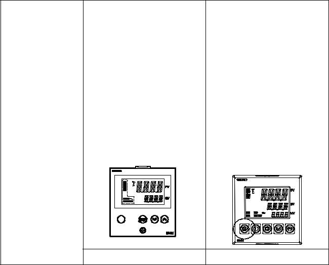
E5CN
E5AN
E5EN
E5GN
Digital Temperature Controllers
SUB1 |
|
PV |
SUB2 |
|
|
|
|
|
SUB3 |
|
|
HA |
|
|
|
|
SV |
OUT1 |
STOP |
MV |
OUT2 |
CMW MANU |
|
PF
A/M
SUB1
 SUB2
SUB2
HA 
 SUB3
SUB3
PV
SV
OUT1 STOP |
MV |
OUT2
 CMW
CMW
 MANU
MANU
PF
A/M
E5AN |
E5EN |
User's Manual
Basic Type
Cat. No. H156-E1-03
E5CN/E5AN/E5EN/E5GN
Digital Temperature Controllers
User’s Manual
Basic Type
Revised September 2009
iv
Preface
The E5CN, E5CN-U, E5AN, E5EN, and E5GN are Digital Temperature Controllers. The E5CN and E5CN-U are both compact temperature controllers, with the E5CN featuring screw terminal connections, and the E5CN-U featuring socket pin connections. The E5GN can be connected using screw terminals or screwless clamp terminals. The main functions and characteristics of these Digital Temperature Controllers are as follows:
•Any of the following types of input can be used: thermocouple, platinum resistance thermometer, infrared sensor, analog voltage, or analog current.
•Either standard or heating/cooling control can be performed.
•Both auto-tuning and self-tuning are supported.
•Event inputs can be used to switch set points (multi-SP function), switch between RUN and STOP status, switch between automatic and manual operation, start/reset the simple program function, and perform other operations. (Event inputs are not applicable to the E5CN-U.)
•Heater burnout detection, heater short (HS) alarms, and heater overcurrent (OC) functions are supported. (Applicable to E5CN, E5AN, E5EN, and E5GN models with heater burnout detection function.)
•Communications are supported. (Applicable to E5CN, E5AN, E5EN, and E5GN models with communications.)
•User calibration of the sensor input is supported.
•The structure is waterproof (IP66). (Not applicable to the E5CN-U.)
•Conforms to UL, CSA, and IEC safety standards and EMC Directive.
•The PV display color can be switched to make process status easy to understand at a glance.
This manual describes the E5CN, E5CN-U, E5AN, E5EN, and E5GN. Read this manual thoroughly and be sure you understand it before attempting to use the Digital Temperature Controller and use the Digital Temperature Controller correctly according to the information provided. Keep this manual in a safe place for easy reference. Refer to the following manual for further information on communications:
E5CN/E5AN/E5EN/E5GN Digital Temperature Controllers Communications Manual Basic Type (Cat. No. H158).
Refer to the following manual for information on the Advanced Type Controllers: E5CN/E5AN/E5EN-H Digital Temperature Controllers User's Manual Advanced Type (Cat. No. H157).
Visual Aids
The following headings appear in the left column of the manual to help you locate different types of information.
Note Indicates information of particular interest for efficient and convenient operation of the product.
1,2,3... 1. Indicates lists of one sort or another, such as procedures, checklists, etc.
v
OMRON, 2008
All rights reserved. No part of this publication may be reproduced, stored in a retrieval system, or transmitted, in any form, or by any means, mechanical, electronic, photocopying, recording, or otherwise, without the prior written permission of OMRON.
No patent liability is assumed with respect to the use of the information contained herein. Moreover, because OMRON is constantly striving to improve its high-quality products, the information contained in this manual is subject to change without notice. Every precaution has been taken in the preparation of this manual. Nevertheless, OMRON assumes no responsibility for errors or omissions. Neither is any liability assumed for damages resulting from the use of the information contained in this publication.
vi

Read and Understand this Manual
Please read and understand this manual before using the products. Please consult your OMRON representative if you have any questions or comments.
Warranty, Limitations of Liability
WARRANTY
OMRON's exclusive warranty is that the products are free from defects in materials and workmanship for a period of one year (or other period if specified) from date of sale by OMRON.
OMRON MAKES NO WARRANTY OR REPRESENTATION, EXPRESS OR IMPLIED, REGARDING NONINFRINGEMENT, MERCHANTABILITY, OR FITNESS FOR PARTICULAR PURPOSE OF THE PRODUCTS. ANY BUYER OR USER ACKNOWLEDGES THAT THE BUYER OR USER ALONE HAS DETERMINED THAT THE PRODUCTS WILL SUITABLY MEET THE REQUIREMENTS OF THEIR INTENDED USE. OMRON DISCLAIMS ALL OTHER WARRANTIES, EXPRESS OR IMPLIED.
LIMITATIONS OF LIABILITY
OMRON SHALL NOT BE RESPONSIBLE FOR SPECIAL, INDIRECT, OR CONSEQUENTIAL DAMAGES, LOSS OF PROFITS OR COMMERCIAL LOSS IN ANY WAY CONNECTED WITH THE PRODUCTS, WHETHER SUCH CLAIM IS BASED ON CONTRACT, WARRANTY, NEGLIGENCE, OR STRICT LIABILITY.
In no event shall the responsibility of OMRON for any act exceed the individual price of the product on which liability is asserted.
IN NO EVENT SHALL OMRON BE RESPONSIBLE FOR WARRANTY, REPAIR, OR OTHER CLAIMS REGARDING THE PRODUCTS UNLESS OMRON'S ANALYSIS CONFIRMS THAT THE PRODUCTS WERE PROPERLY HANDLED, STORED, INSTALLED, AND MAINTAINED AND NOT SUBJECT TO CONTAMINATION, ABUSE, MISUSE, OR INAPPROPRIATE MODIFICATION OR REPAIR.
Application Considerations
SUITABILITY FOR USE
OMRON shall not be responsible for conformity with any standards, codes, or regulations that apply to the combination of the products in the customer's application or use of the products.
At the customer's request, OMRON will provide applicable third party certification documents identifying ratings and limitations of use that apply to the products. This information by itself is not sufficient for a complete determination of the suitability of the products in combination with the end product, machine, system, or other application or use.
The following are some examples of applications for which particular attention must be given. This is not intended to be an exhaustive list of all possible uses of the products, nor is it intended to imply that the uses listed may be suitable for the products:
•Outdoor use, uses involving potential chemical contamination or electrical interference, or conditions or uses not described in this manual.
•Nuclear energy control systems, combustion systems, railroad systems, aviation systems, medical equipment, amusement machines, vehicles, safety equipment, and installations subject to separate industry or government regulations.
•Systems, machines, and equipment that could present a risk to life or property.
Please know and observe all prohibitions of use applicable to the products.
NEVER USE THE PRODUCTS FOR AN APPLICATION INVOLVING SERIOUS RISK TO LIFE OR PROPERTY WITHOUT ENSURING THAT THE SYSTEM AS A WHOLE HAS BEEN DESIGNED TO ADDRESS THE RISKS, AND THAT THE OMRON PRODUCTS ARE PROPERLY RATED AND INSTALLED FOR THE INTENDED USE WITHIN THE OVERALL EQUIPMENT OR SYSTEM.
PROGRAMMABLE PRODUCTS
OMRON shall not be responsible for the user's programming of a programmable product, or any consequence thereof.
vii

Disclaimers
CHANGE IN SPECIFICATIONS
Product specifications and accessories may be changed at any time based on improvements and other reasons.
It is our practice to change model numbers when published ratings or features are changed, or when significant construction changes are made. However, some specifications of the products may be changed without any notice. When in doubt, special model numbers may be assigned to fix or establish key specifications for your application on your request. Please consult with your OMRON representative at any time to confirm actual specifications of purchased products.
DIMENSIONS AND WEIGHTS
Dimensions and weights are nominal and are not to be used for manufacturing purposes, even when tolerances are shown.
PERFORMANCE DATA
Performance data given in this manual is provided as a guide for the user in determining suitability and does not constitute a warranty. It may represent the result of OMRON's test conditions, and the users must correlate it to actual application requirements. Actual performance is subject to the OMRON Warranty and Limitations of Liability.
ERRORS AND OMISSIONS
The information in this manual has been carefully checked and is believed to be accurate; however, no responsibility is assumed for clerical, typographical, or proofreading errors, or omissions.
viii
Safety Precautions
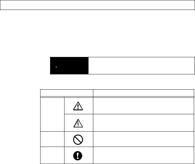
■ Definition of Precautionary Information
The following notation is used in this manual to provide precautions required to ensure safe usage of the product.
The safety precautions that are provided are extremely important to safety.
Always read and heed the information provided in all safety precautions.
The following notation is used.
Indicates a potentially hazardous situation which, if not  CAUTION avoided, is likely to result in minor or moderate injury or in
property damage.
■ Symbols
Symbol |
Meaning |
General Caution
Indicates non-specific general cautions, warnings, and
dangers.
Caution
Electrical Shock Caution
Indicates possibility of electric shock under specific conditions.
Prohibition
General Prohibition
Indicates non-specific general prohibitions.
Mandatory
General Caution
Caution
Indicates non-specific general cautions, warnings, and dangers.
ix
■ Safety Precautions
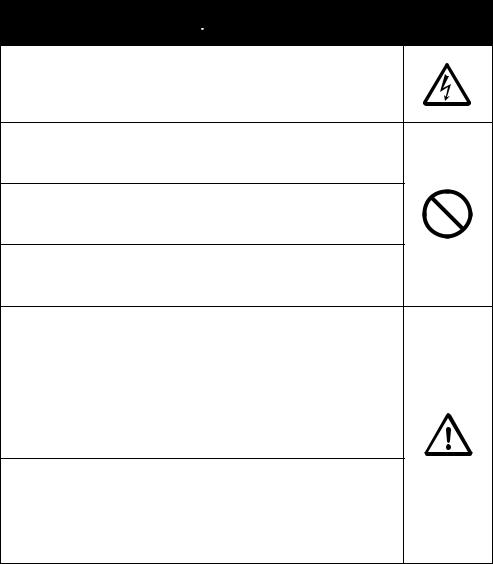
 CAUTION
Do not touch the terminals while power is being supplied. Doing so may occasionally result in minor injury due to electric shock.
Do not allow pieces of metal, wire clippings, or fine metallic shavings or filings from installation to enter the product. Doing so may occasionally result in electric shock, fire, or malfunction.
Do not use the product where subject to flammable or explosive gas. Otherwise, minor injury from explosion may occasionally occur.
Never disassemble, modify, or repair the product or touch any of the internal parts. Minor electric shock, fire, or malfunction may occasionally occur.
CAUTION - Risk of Fire and Electric Shock
a)This product is UL listed as Open Type Process Control Equipment. It must be mounted in an enclosure that does not allow fire to escape externally.
b)More than one disconnect switch may be required to deenergize the equipment before servicing the product.
c)Signal inputs are SELV, limited energy. *1
d)Caution: To reduce the risk of fire or electric shock, do not interconnect the outputs of different Class 2 circuits.*2
If the output relays are used past their life expectancy, contact fusing or burning may occasionally occur.
Always consider the application conditions and use the output relays within their rated load and electrical life expectancy. The life expectancy of output relays varies considerably with the output load and switching conditions.
*1 A SELV circuit is one separated from the power supply with double insulation or reinforced insulation, that does not exceed 30 V r.m.s. and 42.4 V peak or 60 VDC.
*2 A class 2 power supply is one tested and certified by UL as having the current and voltage of the secondary output restricted to specific levels.
x
 CAUTION
Tighten the terminal screws to between 0.74 and 0.90 N·m. Loose screws may occasionally result in fire. *3
Set the parameters of the product so that they are suitable for the system being controlled. If they are not suitable, unexpected operation may occasionally result in property damage or accidents.
A malfunction in the Temperature Controller may occasionally make control operations impossible or prevent alarm outputs, resulting in property damage. To maintain safety in the event of malfunction of the Temperature Controller, take appropriate safety measures, such as installing a monitoring device on a separate line.
A semiconductor is used in the output section of long-life relays. If excessive noise or surge is impressed on the output terminals, a short-circuit failure is likely to occur. If the output remains shorted, fire will occur due to overheating of the heater or other cause.
Take measures in the overall system to prevent excessive temperature increase and to prevent fire from spreading.
When inserting the body of the Temperature Controller into the case, confirm that the hooks on the top and bottom are securely engaged with the case. If the body of the Temperature Controller is not inserted properly, faulty contact in the terminal section or reduced water resistance may occasionally result in fire or malfunction.
*3 The tightening torque is 0.5 N·m for the E5CN-U and 0.43 to 0.58 N·m for the E5GN. The terminal torque is 0.5 to 0.6 N·m for auxiliary output 2 on the E5GN.
xi

Precautions for Safe Use
Be sure to observe the following precautions to prevent operation failure, malfunction, or adverse affects on the performance and functions of the product. Not doing so may occasionally result in unexpected events. Use the product within the specifications.
1)The product is designed for indoor use only. Do not use the product outdoors or in any of the following locations. Do not use or store the product in any of the following locations.
•Places directly subject to heat radiated from heating equipment.
•Places subject to splashing liquid or oil atmosphere.
•Places subject to direct sunlight.
•Places subject to dust or corrosive gas (in particular, sulfide gas and ammonia gas).
•Places subject to intense temperature change.
•Places subject to icing and condensation.
•Places subject to vibration and large shocks.
2)Use and store the Digital Temperature Controller within the rated ambient temperature and humidity. Gang-mounting two or more temperature controllers, or mounting temperature controllers above each other may cause heat to build up inside the temperature controllers, which will shorten their service life. In such a case, use forced cooling by fans or other means of air ventilation to cool down the Digital Temperature Controllers.
3)To allow heat to escape, do not block the area around the product. Do not block the ventilation holes on the product.
4)Be sure to wire properly with correct polarity of terminals.
5)Use the specified size of crimp terminals for the E5CN, E5AN, or E5EN (M3.5, width of 7.2 mm or less). For open-wired connections to the E5CN, E5AN, or E5EN, use stranded or solid copper wires with a gauge of AWG24 to AWG14 (equal to a cross-sectional area of 0.205 to 2.081 mm2). (The stripping length is 5 to 6 mm.) Up to two wires of the same size and type or two crimp terminals can be connected to one terminal. Do not connect more than two wires or more than two crimp terminals to the same terminal.
Use the specified size of crimp terminals for the E5GN (M3.0, width of 5.8 mm or less). For open-wired connections to the E5GN, use stranded or solid copper wires with a gauge of AWG24 to AWG18 (equal to a cross-sectional area of 0.205 to 0.8231 mm2). (The stripping length for screw terminals is 6 to 8 mm. The stripping length for screwless clamp terminals is 10 mm. The stripping length for auxiliary output 2 is 6 mm.) Up to two wires of the same size and type or two crimp terminals can be connected to one terminal. Do not connect more than two wires or more than two crimp terminals to the same terminal.
Ferrules for screwless clamp terminals must be 0.8 to 1.4 mm in diameter and the exposed conductor must be 8 to 12 mm in length. Ferrules for auxiliary output 2 must be 0.8 to 1.4 mm in diameter and the exposed conductor must be 6 mm in length.
6)Do not wire the terminals which are not used.
7)To avoid inductive noise, keep the wiring for the Digital Temperature Controller's terminal block away from power cables carry high voltages or large currents. Also, do not wire power lines together with or parallel to Digital Temperature Controller wiring. Using shielded cables and using separate conduits or ducts is recommended.
Attach a surge suppressor or noise filter to peripheral devices that generate noise (in particular, motors, transformers, solenoids, magnetic coils or other equipment that have an inductance component).
When a noise filter is used at the power supply, first check the voltage or current, and attach the noise filter as close as possible to the temperature controller.
Allow as much space as possible between the Digital Temperature Controller and devices that generate powerful high frequencies (high-frequency welders, high-frequency sewing machines, etc.) or surge.
8)Use this product within the rated load and power supply.
9)Make sure that the rated voltage is attained within two seconds of turning ON the power using a switch or relay contact. If the voltage is applied gradually, the power may not be reset or output malfunctions may occur.
xii
10)Make sure that the Temperature Controller has 30 minutes or more to warm up after turning ON the power before starting actual control operations to ensure the correct temperature display.
11)When executing self-tuning, turn ON power for the load (e.g., heater) at the same time as or before supplying power to the Digital Temperature Controller. If power is turned ON for the Digital Temperature Controller before turning ON power for the load, self-tuning will not be performed properly and optimum control will not be achieved.
12)A switch or circuit breaker should be provided close to this unit. The switch or circuit breaker should be within easy reach of the operator, and must be marked as a disconnecting means for this unit.
13)Always turn OFF the power supply before removing the body of the E5CN, E5AN, or E5EN from the case, and never touch nor apply shock to the terminals or electronic components. When inserting the interior of the product, do not allow the electronic components to touch the case.
Always turn OFF the power supply before removing the terminal block from the E5GN, and never touch nor apply shock to the terminals or electronic components.
14)Do not use paint thinner or similar chemical to clean with. Use standard grade alcohol.
15)Design system (control panel, etc.) considering the 2 second of delay that the controller’s output to be set after power ON.
16)The output may turn OFF when shifting to certain levels. Take this into consideration when performing control.
17)The number of EEPROM write operations is limited. Therefore, use RAM write mode when frequently overwriting data during communications or other operations.
18)Always touch a grounded piece of metal before touching the Digital Temperature Controller to discharge static electricity from your body.
19)Do not remove the terminal block from the E5CN, E5AN, or E5EN. Doing so may result in failure or malfunction.
20)Control outputs that are voltage outputs are not isolated from the internal circuits. When using a grounded thermocouple, do not connect any of the control output terminals to ground. (Doing so may result in an unwanted circuit path, causing error in the measured temperature.)
21)When replacing the body of the E5CN, E5AN, or E5EN, check the condition of the terminals. If corroded terminals are used, contact failure in the terminals may cause the temperature inside the E5CN, E5AN, or E5EN to increase, possibly resulting in fire. If the terminals are corroded, replace the case as well.
When removing the terminal block of the E5GN to replace the Digital Temperature Controller, check the condition of the terminals. If corroded terminals are used, contact failure in the terminals may cause the temperature inside the Digital Temperature Controller to increase, possibly resulting in fire. If the terminals are corroded, replace the terminal block as well.
22)Use suitable tools when taking the Digital Temperature Controller apart for disposal. Sharp parts inside the Digital Temperature Controller may cause injury.
23)When applying Lloyd's standards, install the Digital Temperature Controller according to the requirements given in Shipping Standards.
24)Do not use the Temperature Controller if the front sheet is peeling off or torn.
● Service Life
Use the Temperature Controller within the following temperature and humidity ranges: Temperature: −10 to 55°C (with no icing or condensation), Humidity: 25% to 85%
If the Controller is installed inside a control board, the ambient temperature must be kept to under 55°C, including the temperature around the Controller.
The service life of electronic devices like Temperature Controllers is determined not only by the number of times the relay is switched but also by the service life of internal electronic components. Component service life is affected by the ambient temperature: the higher the temperature, the shorter the service life and, the lower the temperature, the longer the service life. Therefore, the service life can be extended by lowering the temperature of the Temperature Controller.
xiii
When two or more Temperature Controllers are mounted horizontally close to each other or vertically next to one another, the internal temperature will increase due to heat radiated by the Temperature Controllers and the service life will decrease. In such a case, use forced cooling by fans or other means of air ventilation to cool down the Temperature Controllers. When providing forced cooling, however, be careful not to cool down the terminals sections alone to avoid measurement errors.
● Ambient Noise
To avoid inductive noise, keep the wiring for the Digital Temperature Controller's terminal block wiring away from power cables carrying high voltages or large currents. Also, do not wire power lines together with or parallel to Digital Temperature Controller wiring. Using shielded cables and using separate conduits or ducts is recommended.
Attach a surge suppressor or noise filter to peripheral devices that generate noise (in particular, motors, transformers, solenoids, magnetic coils or other equipment that have an inductance component). When a noise filter is used at the power supply, first check the voltage or current, and attach the noise filter as close as possible to the Temperature Controller.
Allow as much space as possible between the Digital Temperature Controller and devices that generate powerful high frequencies (high-frequency welders, high-frequency sewing machines, etc.) or surge.
● Ensuring Measurement Accuracy
When extending or connecting the thermocouple lead wire, be sure to use compensating wires that match the thermocouple types.
When extending or connecting the lead wire of the platinum resistance thermometer, be sure to use wires that have low resistance and keep the resistance of the three lead wires the same.
Mount the Temperature Controller so that it is horizontally level.
If the measurement accuracy is low, check to see if input shift has been set correctly.
● Waterproofing
The degree of protection is as shown below. Sections without any specification on their degree of protection or those with IP@0 are not waterproof.
Front panel: IP66
Rear case: IP20, Terminal section: IP00
(E5CN-U: Front panel: IP50, rear case: IP20, terminals: IP00)
xiv

Precautions for Operation
1)It takes approximately two seconds for the outputs to turn ON from after the power supply is turned ON. Due consideration must be given to this time when incorporating Temperature Controllers into a control panel or similar device.
2)Make sure that the Temperature Controller has 30 minutes or more to warm up after turning ON the power before starting actual control operations to ensure the correct temperature display.
3)When executing self-tuning, turn ON power for the load (e.g., heater) at the same time as or before supplying power to the Temperature Controller. If power is turned ON for the Temperature Controller before turning ON power for the load, self-tuning will not be performed properly and optimum control will not be achieved. When starting operation after the Temperature Controller has warmed up, turn OFF the power and then turn it ON again at the same time as turning ON power for the load. (Instead of turning the Temperature Controller OFF and ON again, switching from STOP mode to RUN mode can also be used.)
4)Avoid using the Controller in places near a radio, television set, or wireless installing. The Controller may cause radio disturbance for these devices.
Shipping Standards
The E5CN, E5CN-H, E5AN, E5AN-H, E5EN, and E5EN-H comply with Lloyd's standards. When applying the standards, the following installation and wiring requirements must be met in the application.
■ Application Conditions
1) Installation Location
The E5CN, E5CN-H, E5AN, E5AN-H, E5EN, and E5EN-H comply with installation category ENV1 and ENV2 of Lloyd's standards. Therefore, they must be installed in a location equipped with air conditioning. They must therefore be installed in a location equipped with air conditioning. They cannot be used on the bridge or decks, or in a location subject to strong vibration.
2) Wiring Conditions
Install the recommended ferrite core and wrap the line around it three turns for the applicable lines (e.g., power supply cable line and signal lines) of the models listed in the following table. (See illustrations.) Install the ferrite cores as close to the terminal block of the E5@N as possible. (As a guideline, the ferrite core should be within 10 cm of the terminal block.)
● Lines Requiring Ferrite Cores
Model |
Signal and power lines provided with ferrite cores |
|
|
E5CN, E5CN-U, or E5CN-H |
Input power supply |
|
|
E5EN, E5AN, E5EN-H, or |
Input power supply and I/O lines (control outputs (1 and 2), communications, |
E5AN-H |
event inputs (1 to 4), transfer output, and external power supply (Advanced |
|
Type models do not have an external power supply.) |
|
|
● Recommended Ferrite Core
Manufacturer |
Seiwa Electric Mfg. Co., Ltd. |
|
|
Model |
E04RA310190100 |
|
|
xv

● Ferrite Core Connection Examples
1. E5CN/E5CN-H
|
|
|
|
|
|
|
|
|
|
Auxiliary outputs |
|
|
|
|
+ |
|
|
1 |
11 |
6 |
(relay outputs) |
|
|
|
|
|
|
|
|
|||
|
|
|
|
Control output 1 |
2 |
|
|
Auxiliary output 2 |
||
|
|
|
|
− |
|
|
12 |
7 |
Auxiliary |
|
|
+ |
|
|
|
A |
|
|
|
||
|
DO NOT |
DO NOT |
|
|
|
● |
||||
|
|
|
3 |
13 |
8 |
output 1 |
||||
|
|
USE |
|
USE |
|
|
|
|||
mA |
|
|
|
|
|
|
|
|
||
|
|
− |
− |
|
B |
4 |
14 |
9 |
|
|
|
− |
|
● |
|
||||||
|
|
|
|
|
|
Input power |
||||
|
V |
|
● |
|
|
|
|
|
||
|
|
|
|
|
B |
|
|
|
supply |
|
|
DO NOT |
+ |
+ |
|
5 |
15 |
10 |
|||
|
|
|
|
|||||||
|
USE |
|
|
|
|
|
|
|
||
|
|
|
|
|
|
|
|
|
|
|
|
Analog input |
|
TC/Pt universal input |
|
|
|
||||
2. E5AN/E5EN/E5AN-H/E5EN-H
Power supply
AC/DC
3 turns
Power |
|
3 turns |
|
1 |
21 |
11 |
Event Inputs |
|
|
|
|
|
|
||
AC/DC |
|
|
|
|
|
|
|
|
|
Connected to |
|||||
|
Input power |
|
|
|
|
|
|
|
|
||||||
|
|
|
|
|
|
|
|
|
|
|
|
||||
supply |
|
|
supply |
2 |
22 |
12 |
EV2 |
|
|
|
|
3 turns |
|
communications or |
|
|
|
|
|
EV1 |
|
|
|
event inputs 1 and 2. |
|||||||
|
|
|
|
|
|
|
|
|
|
||||||
|
|
|
+ |
3 |
23 |
13 |
|
|
Control |
|
External Power |
|
|||
Connected to |
|
|
CT1/CT2 |
Output 2 |
|
Supply |
|
|
|
||||||
|
Control output 1 |
|
|
|
|
|
|
|
|
|
|||||
control output 1. |
3 turns |
4 |
24 |
14 |
|
+ |
|
+ |
|
|
|
||||
− |
|
|
|
|
|
||||||||||
|
|
CT1 |
|
Control |
External power supply |
|
|||||||||
|
|
|
|
|
|
|
|
||||||||
|
|
|
|
|
|
|
|
Output 2 12 VDC, 20 mA |
|
|
|||||
|
|
|
|
5 |
25 |
15 |
|
|
|
3 turns |
|||||
|
|
|
|
CT2 |
− |
|
− |
|
|
||||||
|
|
|
Auxiliary output 3 |
|
|
|
|
|
|
|
|||||
|
|
|
6 |
26 |
16 |
|
DO NOT |
|
|
DO NOT |
|
|
|||
|
|
|
|
|
|
|
|
|
|
||||||
|
|
|
|
|
|
USE |
|
|
USE |
|
|
|
|||
|
|
|
|
7 |
27 |
17 |
DO NOT |
|
|
|
|
|
|
|
|
|
|
|
|
USE |
|
|
|
|
|
|
|
|
|||
|
|
|
Auxiliary output 2 |
|
|
|
|
|
|
|
|
|
|
|
|
|
|
|
|
|
|
DO NOT |
|
A |
DO NOT |
+ |
|
|
|||
|
|
|
|
8 |
28 |
18 |
|
|
|
||||||
|
|
|
|
|
|
|
|
|
|||||||
|
|
|
|
USE |
|
|
USE |
|
|
|
|
|
|||
|
|
|
|
|
|
|
|
|
|
|
mA |
|
|
||
|
|
|
|
|
|
|
− |
|
B |
− |
|
|
|
|
|
|
|
|
|
9 |
29 |
19 |
|
|
|
|
|
|
|||
|
|
|
|
|
|
|
|
|
|
− |
|
|
|||
|
|
|
Auxiliary output 1 |
|
|
|
|
|
|
V |
|
|
|
||
|
|
|
|
|
|
|
|
B |
DO NOT |
|
|||||
|
|
|
|
10 |
30 |
20 |
|
|
|
|
|
||||
|
|
|
|
+ |
|
|
+ |
|
USE |
|
|
||||
|
|
|
|
|
|
|
|
|
|
|
|
||||
|
|
|
|
|
|
|
|
|
|
|
|
|
|
||
|
|
|
|
|
|
TC/Pt universal input |
Analog input |
|
|||||||
|
|
|
|
|
|
|
|
|
|
|
Communications |
|
|||
|
|
|
|
|
21 |
|
|
RS-232C |
|
|
|
|
RS-485 |
|
|
|
|
|
|
|
|
|
|
|
|
|
|
|
|||
|
|
|
|
|
22 |
|
|
11 |
SD |
|
|
|
|
11 |
B (+) |
|
|
|
|
|
23 |
|
|
12 |
RD |
|
|
|
|
12 |
A (−) |
|
|
|
|
EV3 |
|
|
13 |
SG |
|
|
|
|
13 |
DO NOT USE |
|
|
Connected to event |
|
|
|
|
|
|
|
|
|
|||||
|
|
|
|
24 |
|
|
|
|
|
|
|
|
|
|
|
|
inputs 3 and 4. |
3 turns |
|
EV4 |
|
|
21 |
DO NOT USE |
|
21 |
B (+) |
||||
|
|
|
|
|
|
|
|
|
|
|
|
|
A (−) |
||
|
|
|
|
|
25 |
|
|
22 |
DO NOT USE |
|
22 |
||||
|
DO NOT USE |
26 |
|
Connected to |
+ |
27 |
|
Transfer output |
4 to 20 mA DC |
||
transfer output. |
|
(Load: 600 Ω max.) |
|
3 turns |
28 |
||
|
− |
|
|
|
DO NOT USE |
29 |
|
|
DO NOT USE |
30 |
|
Connected to control output 2 or external power supply.
xvi

Preparations for Use
Be sure to thoroughly read and understand the manual provided with the product, and check the following points.
Timing |
Check point |
Details |
|
|
|
Purchasing the prod- |
Product appearance |
After purchase, check that the product and packaging are not dented or |
uct |
|
otherwise damaged. Damaged internal parts may prevent optimum |
|
|
control. |
|
|
|
|
Product model and speci- |
Make sure that the purchased product meets the required specifica- |
|
fications |
tions. |
|
|
|
Setting the Unit |
Product installation loca- |
Provide sufficient space around the product for heat dissipation. Do not |
|
tion |
block the vents on the product. |
|
|
|
Wiring |
Terminal wiring |
Do not subject the terminal screws to excessive stress (force) when |
|
|
tightening them. |
|
|
Make sure that there are no loose screws after tightening terminal |
|
|
screws to the specified torque of 0.74 to 0.90 N·m (see note). |
|
|
Be sure to confirm the polarity for each terminal before wiring the termi- |
|
|
nal block and connectors. |
|
|
|
|
Power supply inputs |
Wire the power supply inputs correctly. Incorrect wiring will result in |
|
|
damage to the internal circuits. |
|
|
|
Operating environ- |
Ambient temperature |
The ambient operating temperature for the product is −10 to 55°C (with |
ment |
|
no condensation or icing). To extend the service life of the product, |
|
|
install it in a location with an ambient temperature as low as possible. In |
|
|
locations exposed to high temperatures, if necessary, cool the products |
|
|
using a fan or other cooling method. |
|
|
|
|
Vibration and shock |
Check whether the standards related to shock and vibration are satis- |
|
|
fied at the installation environment. (Install the product in locations |
|
|
where the conductors will not be subject to vibration or shock.) |
|
|
|
|
Foreign particles |
Install the product in a location that is not subject to liquid or foreign |
|
|
particles entering the product. |
|
|
|
Note The tightening torque is 0.5 N·m for the E5CN-U and 0.43 to 0.58 N·m for the E5GN. The terminal torque is 0.5 to 0.6 N·m for auxiliary output 2 on the E5GN.
xvii

■ Upgraded Functions
The functionality of the E5CN, E5CN-U, E5AN, and E5EN was improved starting from December 2007 production.
The functionality of the E5GN was improved starting from August 2009 production.
The design of the front panel can be used to differentiate between the previous and upgraded models.
● E5CN/CN-U
The upgraded Controllers are basically compatible with the previous Controllers. Terminal arrangements, terminal sizes, and panel mounting depth have not been changed.
● E5AN/EN
Although the upgraded Controllers are compatible with the previous Controllers, terminal arrangements have been changed. Terminal sizes and panel mounting depth have not been changed.
● E5GN
Model numbers have changed accompanying the introduction of universal input capability. The default setting of the input type parameter of the E5GN-@@@P (models with resistance thermometers) has been changed from a Pt100 resistance thermometer to a K thermocouple. Make sure the setting of the input type parameter agrees with the temperature sensor that is being used.
The terminal block has also been changed, which means the wiring methods and terminal arrangement are different.
Other changes outlined in the following tables. Refer to relevant pages in the manual for details.
Previous models |
Upgraded models |
E5CN/CN-U
• ALM indicator was changed to SUB indicator.
E5AN
• Number of displays: 2 (PV and SV) |
• Number of displays: 3 (PV, SV, and MV) * |
|
• ALM indicator was changed to SUB indicator. |
xviii

Previous models |
Upgraded models |
E5EN
• Number of displays: 2 (PV and SV) |
• Number of displays: 3 (PV, SV, and MV) * |
|
• ALM indicator was changed to SUB indicator. |
E5GN
• Display Segments |
• Display Segments |
PV: 7 segments, |
PV: 11 segments, |
SV: 7 segments |
SV: 11 segments |
• Character Heights |
• Character Heights |
PV: 7 mm, SV: 3.5 mm |
PV: 7.5 mm, SV: 3.6 mm |
|
• Changes to Display Contents |
|
"AL" LED indicator eliminated, LED indicators |
|
added, and key indicator added. |
*A 2-level display is set when shipped from the factory.
A 3-level display is activated if parameters are initialized.
xix

■ Terminal Arrangements
|
|
|
Previous models |
|
|
|
|
Upgraded models |
|
|||||||
E5AN/EN |
Terminals 16 through 20 were changed. Terminals 1 through |
|
One CT |
Control Output 2 |
|
External power |
||||||||||
|
15 were not changed. |
|
|
|
|
|
|
|
|
supply |
|
|||||
|
|
|
|
|
|
|
|
Two CTs |
|
|
||||||
|
|
Voltage output |
Long-life relay |
External power |
One CT |
14 |
|
|
+ |
+ |
|
|
||||
|
|
|
|
|
|
|
External power |
|||||||||
|
|
|
output |
|
supply for ES1B |
Two CTs |
|
|
CT1 |
Control Output 2 |
|
|||||
|
|
|
|
|
|
|
supply |
|
||||||||
|
14 |
+ |
14 Control Output 2 |
14 |
+ |
14 |
|
15 |
|
|
− |
− |
12 VDC, 20 mA |
|||
|
|
|
CT2 |
|
|
|||||||||||
|
CT1 |
|
|
|
|
|
|
|
||||||||
|
|
Control Output 2 |
250 VAC, 3 A |
|
12 VDC, 20 mA |
16 |
|
|
DO NOT |
|
DO NOT |
|
||||
|
|
12 VDC, 21 mA |
|
|
|
|
|
|
||||||||
|
|
15 (Resistive load) 15 |
− |
|
|
|
|
USE |
|
USE |
|
|||||
|
15 |
− |
15 |
CT2 |
|
DO NOT |
|
|
|
|
|
|||||
|
|
A |
|
+ |
|
|
|
17 |
|
|
|
|
|
|||
|
16 |
|
|
|
|
|
USE |
|
|
|
|
|
|
|||
|
|
|
|
|
|
|
|
|
|
|
|
|
|
+ |
||
|
|
− B |
− |
mA |
|
|
|
|
18 |
DO NOT |
A |
DO NOT |
||||
|
17 |
− |
|
|
|
|
|
USE |
|
|
USE |
mA |
||||
|
|
|
|
|
|
|
|
− |
|
B |
|
|
− |
− |
||
|
|
B |
V |
|
|
|
|
19 |
|
|
|
|||||
|
18 |
|
|
|
|
|
|
|
|
|
|
V |
||||
|
+ |
+ |
|
|
|
|
|
20 |
|
|
B |
|
|
DO NOT |
||
|
|
|
|
|
|
|
+ |
|
|
|
+ |
|||||
|
|
|
|
|
|
|
|
|
|
|
USE |
|||||
|
19 |
TC/Pt universal input |
Analog input |
|
|
19 |
|
|
|
|
|
|
|
|||
|
|
|
|
TC/Pt universal input |
|
|
Analog input |
|||||||||
|
|
|
|
|
|
|
|
|
|
|
||||||
|
|
Previous models |
|
|
E5GN |
Number of terminals: 9 (1 to 9) |
|
||
|
Input terminals: 7 to 9 |
|
|
|
|
RS-485 communications terminals: 5 |
|||
|
Input |
+ Control − |
B(+) A(−) |
− |
|
|
|||
|
power |
output 1 |
Communications |
|
|
supply |
|
|
|
|
12 VDC 21 mA |
|
||
|
100 to 240 VAC or |
A |
||
|
|
|
||
|
24 VAC/DC (no polarity) |
|
|
|
|
|
Relay output |
Alarm output 1, |
|
|
|
(OUT1) |
control output 2, |
− |
|
|
|
or input error |
|
|
|
|
|
|
|
|
|
alarm 1/output 1 |
|
|
|
|
(ALM1/OUT1) |
|
and 6
+ TC
B B PT
+
Analog
input
Upgraded models
Number of terminals: 14 (1 to 14) Input terminals: 10 to 12
RS-485 communications terminals: 7 and 8
RS-485 |
B(+) |
|
|
|
|
|
|
|
|
|
|
communications |
|
|
|
DO NOT |
+ |
mA |
|
|
DO NOT |
|
|
|
|
|
|
USE |
|
|
|
USE |
Analog input |
|
|
RS-232C |
|
SD |
RD |
SG |
|
|
|
V |
+ |
|
|
communications |
|
|
|
|
DO NOT |
|
|
|
|||
|
|
|
|
|
|
|
|
||||
|
|
|
|
|
USE |
|
|
|
|
|
|
CT input |
CT |
|
DO NOT |
|
|
|
|
|
|
|
|
|
|
USE |
|
|
|
|
|
|
|
||
|
|
|
|
|
A |
|
B |
|
B |
Universal TC/Pt input |
|
Event input |
|
EV1 |
EV2 |
DO NOT |
|
|
+ |
|
|
||
|
|
|
|
|
USE |
|
|
|
|
|
|
|
|
7 |
8 |
9 |
10 |
|
11 |
|
12 |
|
|
|
|
1 |
2 |
3 |
4 |
|
5 |
|
6 |
13 |
14 |
|
Input power |
|
|
|
|
|
|
Auxiliary |
|
|
+ |
Control |
|
|
Auxiliary |
output 2 |
|
|
supply |
|
output 1 |
|
output 1 |
|
||
|
|
|
||||||
•100 to 240 VAC
•24 VAC/DC (no polarity)
xx
■ Body Drawout
Previous models
E5AN/EN |
• Using Screws |
|
|
|
|
|
|
|
|
|
|
|
|
|
|
|
|
|
|
|
|
|
|
|
|
|
|
|
|
|
|
|
|
|
|
|
|
|
|
|
|
|
|
|
|
|
|
|
|
|
|
|
|
|
|
|
|
|
|
|
|
|
|
|
|
|
|
|
|
|
|
|
|
|
|
|
|
|
|
|
|
|
|
|
|
|
|
|
|
|
|
|
|
|
|
|
|
|
|
|
|
|
|
|
|
|
|
|
|
|
|
|
|
|
|
|
|
|
|
|
|
|
|
|
|
|
|
|
|
|
|
|
|
|
|
|
|
|
|
|
|
|
|
|
|
|
|
|
|
|
|
|
|
|
|
|
|
|
|
|
|
|
|
|
|
|
|
|
|
|
|
|
|
|
|
|
|
|
|
|
|
|
|
|
|
|
|
|
|
|
|
|
|
|
|
|
|
|
|
|
|
|
|
|
|
|
|
|
|
|
|
|
|
|
|
|
|
|
|
|
|
|
|
|
|
|
|
|
|
|
|
|
|
|
|
|
|
|
|
|
|
|
|
|
|
|
|
|
|
|
|
|
|
|
|
|
|
|
|
|
|
|
|
|
|
|
|
|
|
|
|
|
|
|
|
|
|
|
|
|
|
|
|
|
|
|
|
|
|
|
|
|
|
|
|
|
|
|
|
|
|
|
|
|
|
|
|
|
|
|
|
|
|
|
|
|
|
|
|
|
|
|
|
|
|
|
|
|
|
|
|
|
|
|
|
|
|
|
|
|
|
|
|
|
|
|
|
■ Dimensions
|
|
Previous models |
E5GN |
3 |
100 |
|
||
|
35 |
22 |
Bezel thickness: 3 mm
Depth: 100 mm
Upgraded models
• Using Hooks
Upgraded models
•Models with Screw Terminal Blocks Bezel thickness: 2 mm
Depth: 99 mm
Shape of slits changed
2 |
99 |
35 |
22 |
•Models with Screwless Clamp Terminal Blocks Bezel thickness: 2 mm
Shape of slits changed
2 |
100 |
35 |
22 |
xxi

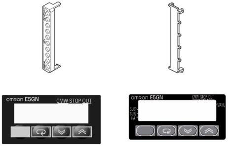
■ Terminal Block Configuration
|
Previous models |
Upgraded models |
|
|
|
E5GN |
• Models with Screw Terminal Blocks |
• Models with Screw Terminal Blocks |
|
Terminals 1 to 6: M2.6 screw terminals |
Terminals 1 to 12: M3 screw terminals |
|
Terminals 7 to 9: M2 screw terminals |
|
|
|
• Models with Screwless Clamp Terminal Blocks |
|
|
Terminals 1 to 12: None |
|
|
|
xxii

■ Wire Connections
|
Previous models |
Upgraded models |
E5GN |
• Wire connection direction: Perpendicular to |
• Models with Screw Terminal Blocks |
|
back surface |
Wire connection direction: Horizontal from the top |
|
|
and bottom of back surface |
• Models with Screwless Clamp Terminal Blocks
Wire connection direction: Perpendicular to back surface
xxiii

■ Wiring Terminals
|
|
|
Previous models |
||||||||
E5GN |
• Models with Screw Terminal Blocks |
||||||||||
|
|
|
|
|
|
|
|
|
|
|
|
|
|
Terminals |
|
Wire gauge |
|
Ferrules |
|||||
|
|
|
|
|
|
|
|
|
|
|
|
|
|
Terminals 1 to 6 |
|
AWG24 to |
|
|
2.1 mm dia. |
||||
|
|
|
|
|
AWG14 |
|
|
max. |
|||
|
|
|
|
|
|
|
|
|
|
|
|
|
|
Terminals 7 to 9 |
|
AWG28 to |
|
|
1.3 mm dia. |
||||
|
|
|
|
|
AWG22 |
|
|
max. |
|||
|
|
|
|
|
|
|
|
|
|
|
|
|
|
|
5 to 6 |
mm |
|
5 to 6 |
mm |
||||
|
|
|
|
|
|
|
|
Ferrules |
|||
|
|
|
Wires |
|
|
|
|||||
|
|
|
|
|
|
|
|
||||
|
|
Terminals |
|
Screws |
|
|
Tightening |
||||
|
|
|
|
|
|
|
|
|
|
torque |
|
|
|
|
|
|
|
|
|||||
|
|
Terminals 1 to 6 |
|
M2.6 |
|
0.23 to 0.25 N·m |
|||||
|
|
|
|
|
|
|
|||||
|
|
Terminals 7 to 9 |
|
M2 |
|
0.12 to 0.14 N·m |
|||||
|
|
|
|
|
|
|
|
|
|
|
|
|
|
|
|
|
|
|
|
|
|
|
|
Upgraded models
•Models with Screw Terminal Blocks
Changed from ferrules to crimp terminals for M3 screws.
Tightening torque: 0.5 N·m
 5.8 mm max.
 5.8 mm max.
•Models with Screwless Clamp Terminal Blocks Wires: Changed to 10 mm from 5 to 6 mm. Ferrules: Changed to 8 to 12 mm from 5 to 6 mm.
|
10 mm |
|
0.8 to 1.4 mm |
|
|
|
8 to 12 mm |
||||
|
|
|
|||||||||
|
|
|
|
|
|
|
|
||||
|
|
|
|
|
|
|
|
||||
|
|
|
|
|
|
|
|
||||
|
|
|
|
|
|
|
|
||||
|
|
|
|
|
|
|
|
||||
|
|
|
|
|
|
|
|
|
|||
|
|
|
|
Ferrules |
|||||||
Wires |
|
|
|
|
|
|
|||||
■ Removing the Terminal Block
|
Previous models |
Upgraded models |
E5GN |
Press firmly in on both sides of the terminal block to |
Insert a tool into the tool holes (one on the top and |
|
release the lock and then pull up on the terminal |
one on the bottom) to release the hooks and pull out |
|
block. |
the terminal block. |
|
|
Terminal hole |
Note The method for removing the terminal block is the same for both screw terminal blocks and screwless clamp terminal blocks.
xxiv
■ Ratings
|
Previous models |
Upgraded models |
|
|
|
|
|
Input sensor types for ther- |
--- |
The following types of thermocouple input |
|
mocouple inputs |
|
were added: W and PLII. |
|
|
|
|
|
|
Input range for E thermocouple: 0 to 600°C |
Input range increased for E thermocouple: |
|
|
|
−200 to 600°C |
|
Input accuracy |
• Thermocouple: (±0.5% PV or ±1°C, which- |
• Thermocouple: (±0.3% PV or ±1°C, which- |
|
(There are no changes in |
ever is greater) ±1 digit |
ever is greater) ±1 digit |
|
thermocouple specifications |
• Platinum resistance thermometer: |
• Platinum resistance thermometer: (±0.2% |
|
for E5CN-U.) |
(±0.5%PV or ±1°C, whichever is greater) |
PV or ±0.8°C, whichever is greater) |
|
|
±1 digit |
±1 digit |
|
|
• Analog input: ±0.5% FS ±1 digit |
• Analog input: ±0.2% FS ±1 digit |
|
Influence of signal source |
• Thermocouple: 0.1°C/Ω (except B, R, S), |
• Thermocouple: 0.1°C/Ω (for all specifica- |
|
resistance |
0.2°C/Ω (B, R, S) |
tions) |
|
|
• Platinum resistance thermometer: 0.4°C/Ω |
• Platinum resistance thermometer: 0.1°C/Ω |
|
Current outputs |
Current output resolution: Approx. 2,700 |
Current output resolution: Approx. 10,000 |
|
|
|
|
|
Auxiliary outputs |
E5CN/E5CN-U/E5GN |
E5CN/E5CN-U |
E5GN |
(alarm outputs) |
250 VAC, 1 A |
250 VAC, 3 A |
250 VAC, 2 A |
|
|
|
|
Input sampling cycle |
E5GN |
E5GN |
|
|
500 ms |
250 ms |
|
|
|
|
|
■ Characteristics
|
Previous models |
Upgraded models |
Model numbers for the E5CN |
Models with 24-VAC/VDC power supply |
A “D” was added to the model numbers for |
|
specifications |
models with 24-VAC/VDC power supply |
|
Example: E5CN-R2MT-500 (24 VAC/VDC) |
specifications. |
|
|
Example: E5CN-R2MTD-500 (24 VAC/VDC) |
|
|
|
Model numbers for the |
Example: E5AN-R3MT-500 (100 to 240 |
“-N” was added to all model numbers |
E5AN/EN |
VAC) |
A “D” was added to the model numbers for |
|
Example: E5AN-R3MT-500 (24 VAC/VDC) |
models with 24-VAC/VDC power supply |
|
|
specifications. |
|
|
Example: |
|
|
• E5AN-R3MT-500-N (100 to 240 VAC) |
|
|
• E5AN-R3MTD-500-N (24 VAC/VDC) |
|
|
|
Model numbers for the |
Examples: E5GN-RTC (100 to 240 VAC) |
• Model numbers have changed accompa- |
E5GN |
E5GN-RP (100 to 240 VAC) |
nying the introduction of universal input |
|
24-VAC/DC Specification |
capability. |
|
Example: E5GN-RTC (24 VAC/DC) |
• A “D” was added to the model numbers for |
|
|
models with 24-VAC/VDC power supply |
|
|
specifications. |
|
|
Example: E5GN-RT (100 to 240 VAC) |
|
|
E5GN-RTD (24 VAC/VDC) |
|
|
|
Front panel |
--- |
PV status display and SV status display |
|
|
|
|
|
PF Key added (E5AN/EN only). |
|
|
|
|
|
|
|
|
|
|
|
|
|
|
|
|
|
|
|
|
|
|
|
|
|
|
|
|
|
|
|
|
|
|
|
|
|
|
|
|
|
|
|
|
|
|
|
|
|
|
|
|
|
|
|
|
|
|
|
|
|
|
|
|
|
|
|
|
|
|
|
|
|
|
|
|
|
|
|
|
|
|
|
|
|
|
|
|
|
|
|
|
|
|
|
|
|
|
|
|
|
|
|
|
|
|
|
|
|
|
|
|
|
|
|
|
|
|
|
|
|
|
|
|
|
|
|
|
|
|
|
|
|
|
|
|
|
|
|
|
|
|
|
|
|
|
|
|
|
|
|
|
|
|
|
|
|
|
|
|
|
|
|
|
|
|
|
|
|
|
|
|
|
|
|
|
|
|
|
|
|
|
|
|
|
|
|
|
|
|
|
|
|
|
|
|
|
|
|
|
|
|
|
|
|
|
|
|
|
|
|
|
|
|
|
|
|
|
|
|
|
|
|
|
|
|
|
|
|
|
|
|
|
|
|
|
|
|
|
|
|
|
|
|
|
|
|
|
|
|
|
|
|
|
|
|
|
|
|
|
|
|
|
|
|
|
|
|
|
|
|
|
|
|
|
|
|
|
|
|
|
|
|
|
|
|
|
|
|
|
|
|
|
|
--- |
|
|
|
|
|
|
|
|
|
|
|
|
|
|
|
|
|
|
|
|
|
|
|
|
|
|
|
|
|
|
|
|
|
|
|
PV/SP display selection for three-level dis- |
|||||
|
|
|
|
|
|
|
|
|
|
|
|
|
|
|
|
|
|
|
|
|
|
|
|
|
|
|
|
|
|
|
|
|
|
|
|||||||
|
|
|
|
|
|
|
|
|
|
|
|
|
|
|
|
|
|
|
|
|
|
|
|
|
|
|
|
|
|
|
|
|
|
|
|||||||
|
|
|
|
|
|
|
|
|
|
|
|
|
|
|
|
|
|
|
|
|
|
|
|
|
|
|
|
|
|
|
|
|
|
|
|
play (E5AN/EN only) * |
|||||
xxv
|
|
Previous models |
Upgraded models |
|
|
|
|
Inputs |
|
--- |
Square root extraction (for models with ana- |
|
|
|
log inputs) |
|
|
|
|
Outputs |
|
--- |
Control output ON/OFF count alarm |
|
|
|
|
|
|
--- |
MV change rate limiter |
|
|
|
|
Controls |
|
--- |
40% AT |
|
|
|
|
|
|
--- |
Automatic cooling coefficient adjustment for |
|
|
|
heating/cooling control |
|
|
|
|
Alarms |
|
--- |
PV rate of change alarm |
|
|
|
|
|
|
--- |
OC alarm (only for models with heater burn- |
|
|
|
out detection) |
|
|
|
|
Other |
|
--- |
Logic operations |
|
|
|
|
|
|
--- |
Inverting direct/reverse operation using |
|
|
|
event inputs or communications commands |
|
* A 2-level display is set when shipped from the factory. |
||
|
|
A 3-level display is activated if parameters are initialized. |
|
xxvi

■ Communications Characteristics
|
Previous models |
Upgraded models |
|
|
|
|
|
Communications |
Double word access only |
|
Word access and double word access |
access size |
|
|
|
|
|
|
|
CompoWay/F services |
--- |
|
Composite Read from Variable Area and Com- |
|
|
|
posite Write to Variable Area |
|
|
|
|
Communications buffer |
40 bytes |
|
217 bytes |
size |
|
|
|
|
|
|
|
Baud rate |
38.4 kbps max. |
E5GN: 19.2k max. |
57.6 kbps max. |
|
|
|
Setup Tool Cable Communications: 38.4k (fixed) |
|
|
|
|
External communica- |
RS-485/RS-232C external communications |
RS-485/RS-232C external communications and |
|
tions |
and Setup Tool communications cannot be |
Setup Tool communications can be used at the |
|
|
used at the same time. |
|
same time. |
|
|
|
|
■ Other Upgrades
Previous models |
Upgraded models |
Mounting Bracket |
|
(E5AN/EN only) |
|
|
Modified section |
|
Mounting Bracket for upgraded models |
|
Mounting Bracket for previous models |
Note |
The Mounting Bracket for the previous |
|||||
|
|
|
|
|||||
|
|
|
|
|
models cannot be used for upgraded |
|||
|
|
|
|
|
models. |
|
|
|
Packing case |
• Previous ID code: N5 |
• New ID code: N6 |
|
|
||||
(E5AN/EN only) |
E5AN-R3MT-500 |
|
|
E5AN-R3MT-500-N |
||||
|
|
|
||||||
|
TYPEE5CN |
T |
|
TYPEE5CNR2T |
||||
|
TEMPERATURE CONTROLLER |
|
TEMPERATURE CONTROLLER |
|||||
|
TEMP. |
|
|
|
|
. |
|
|
|
|
|
|
TEMP. |
|
|
||
|
. |
|
GE |
|
MULTI-RANGEI |
|||
|
LTI-I |
|
||||||
|
MU |
-RAN |
|
|
|
|
|
|
|
VOLTS |
|
|
|
VOLTS |
|
|
|
|
100-24 |
|
|
100-240VAC |
||||
|
- |
0VAC |
|
L |
. |
.1 |
||
|
N5 LOTNo..**** QYT.1.1 |
|
N6 |
OTNo.**** |
QYT.1 |
|||
|
OMRON Corporation MADE IN CHINA |
|
|
|
MADE IN |
|||
|
|
OMRONCorporation MADECHINACHIN |
||||||
Terminal Cover (sold |
• E53-COV10 (for E5CN only) |
• E53-COV17 (for E5CN only) |
||||||
separately) for E5CN |
|
|
|
Note The Terminal Cover for the previous |
||||
|
|
|
|
|||||
|
|
|
|
|
models cannot be used for improved |
|||
|
|
|
|
|
models. |
|
|
|
xxvii
|
Previous models |
Upgraded models |
|
|
|
Terminal Cover (sold |
• E53-COV11 |
• E53-COV16 |
separately) for E5AN/EN |
|
Note The Terminal Cover for the previous |
|
|
|
|
|
models cannot be used for improved |
|
|
models. |
|
|
|
Front Panel Labels |
|
|
(E5GN) |
|
|
|
• Display area dimensions: 36.1 × 9.8 mm |
• The design has been changed. |
|
• Added characters: MANU, SUB1, SUB2, and |
|
|
(W × H) |
HA |
|
|
• Display area dimensions: 36.8 × 10.1 mm (W |
|
|
× H) |
xxviii

|
|
Previous models |
|
Upgraded models |
Body Labels (E5GN) |
1. |
Body labels: 3 |
1. |
Body labels: All labels combined into one la- |
|
2. |
Model number: Refer to the model num- |
|
bel. |
|
|
|
||
|
|
ber legend. |
2. |
Model number: Refer to the model number |
|
3. |
Lot No.: Year of manufacture (last digit of |
|
legend. |
|
3. |
Lot No.: Year of manufacture (last two digits |
||
|
|
year |
||
|
@@@@@@ |
|
of year) |
|
|
1, 2: Manufacture day: 01 to 31 |
@@@@@@@ |
||
|
1, 2: Manufacture day: 01 to 31 |
|||
|
3: Manufacture month: 1 to 9, X, Y, and Z |
|||
|
|
(January to December) |
3: Manufacture month: 1 to 9, X, Y, and Z (Janu- |
|
|
4: Last digit of year. |
|
ary to December) |
|
|
5, 6: Manufacturing factory code |
4, 5: Year of manufacture (last two digits of year) |
||
|
|
|
6, 7: Manufacturing factory code |
|
Top of Controller Bottom of Controller |
Top of Controller |
|
Box Labels (E5GN) |
No ID number |
“N6” has been added to identify the new mod- |
||||
|
|
els. |
||||
|
|
|
|
|
|
|
|
RTC |
|
|
RT |
||
|
Ro |
|
|
|
|
Ro |
|
|
|
|
|
|
|
|
|
|
|
|
|
|
xxix
Conventions Used in This Manual
Model Notation
The E5CN-@@@, E5CN-@@@U, E5AN-@@@, E5EN-@@@, and E5GN-@@@ are given as the E5CN, E5CN-U, E5AN, E5EN, and E5GN when they share functionality.
The following notation is used when specifying differences in functionality.
Notation |
Options |
|
|
E5@N-@@@B |
Two event inputs |
E5@N-@@@03 |
RS-485 communications |
E5@N-@@H |
One of HB, HS, and heater overcurrent detection |
E5@N-@@HH |
Two of HB, HS, and heater overcurrent detection (See note 1.) |
E5@N-@Q |
Control output 2 (voltage output) (See note 1.) |
E5@N-@@P |
External power supply to ES1B (See note 1.) |
E5@N-@@@01 |
RS-232C communications (See note 2.) |
E5@N-@@F |
Transfer output (See note 3.) |
Note: (1) Excluding the E5GN.
(2)Excluding the E5CN.
(3)The E5AN and E5EN only.
Meanings of Abbreviations
The following abbreviations are used in parameter names, figures and in text explanations. These abbreviations mean the following:
Symbol |
Term |
|
|
PV |
Process value |
|
|
SP |
Set point |
|
|
SV |
Set value |
|
|
AT |
Auto-tuning |
|
|
ST |
Self-tuning |
|
|
HB |
Heater burnout |
|
|
HS |
Heater short (See note 1.) |
|
|
OC |
Heater overcurrent |
|
|
LBA |
Loop burnout alarm |
|
|
EU |
Engineering unit (See note 2.) |
|
|
Note: (1) A heater short indicates that the heater remains ON even when the control output from the Temperature Controller is OFF because the SSR has failed or for any other reason.
(2)“EU” stands for Engineering Unit. EU is used as the minimum unit for engineering units such as °C,
m, and g. The size of EU varies according to the input type.
For example, when the input temperature setting range is –200 to +1300°C, 1 EU is 1°C, and when the input temperature setting range is –20.0 to +500.0°C, 1 EU is 0.1°C.
For analog inputs, the size of EU varies according to the decimal point position of the scaling setting, and 1 EU becomes the minimum scaling unit.
xxx
Loading...