


 Loading...
Cat. No. W454-E1-03
SmartSlice
GRT1-DRT
DeviceNet Communications Unit
OPERATION MANUAL
SmartSlice
GRT1-DRT
DeviceNet Communications Unit
Operation Manual
Revised April 2008
iv
Notice:
OMRON products are manufactured for use according to proper procedures by a qualified operator and only for the purposes described in this manual.
The following conventions are used to indicate and classify precautions in this manual. Always heed the information provided with them. Failure to heed precautions can result in injury to people or damage to property.
!DANGER Indicates an imminently hazardous situation which, if not avoided, will result in death or serious injury. Additionally, there may be severe property damage.
!WARNING Indicates a potentially hazardous situation which, if not avoided, could result in death or serious injury. Additionally, there may be severe property damage.
!Caution Indicates a potentially hazardous situation which, if not avoided, may result in minor or moderate injury, or property damage.
OMRON Product References
All OMRON products are capitalized in this manual. The word “Unit” is also capitalized when it refers to an OMRON product, regardless of whether or not it appears in the proper name of the product.
The abbreviation “Ch,” which appears in some displays and on some OMRON products, often means “word” and is abbreviated “Wd” in documentation in this sense.
The abbreviation “PLC” means Programmable Controller. “PC” is used, however, in some Programming Device displays to mean Programmable Controller.
Visual Aids
The following headings appear in the left column of the manual to help you locate different types of information.
Note Indicates information of particular interest for efficient and convenient operation of the product.
1,2,3... 1. Indicates lists of one sort or another, such as procedures, checklists, etc.
OMRON, 2005
All rights reserved. No part of this publication may be reproduced, stored in a retrieval system, or transmitted, in any form, or by any means, mechanical, electronic, photocopying, recording, or otherwise, without the prior written permission of OMRON.
No patent liability is assumed with respect to the use of the information contained herein. Moreover, because OMRON is constantly striving to improve its high-quality products, the information contained in this manual is subject to change without notice. Every precaution has been taken in the preparation of this manual. Nevertheless, OMRON assumes no responsibility for errors or omissions. Neither is any liability assumed for damages resulting from the use of the information contained in this publication.
v
vi
TABLE OF CONTENTS
PRECAUTIONS . . . . . . . . . . . . . . . . . . . . . . . . . . . . . . . . . . . |
xv |
|
1 |
Intended Audience . . . . . . . . . . . . . . . . . . . . . . . . . . . . . . . . . . . . . . . . . . . . . . . . . . . . . . . . . |
xvi |
2 |
General Precautions . . . . . . . . . . . . . . . . . . . . . . . . . . . . . . . . . . . . . . . . . . . . . . . . . . . . . . . . |
xvi |
3 |
Safety Precautions . . . . . . . . . . . . . . . . . . . . . . . . . . . . . . . . . . . . . . . . . . . . . . . . . . . . . . . . . |
xvi |
4 |
Operating Environment Precautions . . . . . . . . . . . . . . . . . . . . . . . . . . . . . . . . . . . . . . . . . . . |
xvii |
5 |
Application Precautions. . . . . . . . . . . . . . . . . . . . . . . . . . . . . . . . . . . . . . . . . . . . . . . . . . . . . |
xviii |
6 |
EC Directives. . . . . . . . . . . . . . . . . . . . . . . . . . . . . . . . . . . . . . . . . . . . . . . . . . . . . . . . . . . . . |
xix |
SECTION 1 |
|
|
Overview . . . . . . . . . . . . . . . . . . . . . . . . . . . . . . . . . . . . . . . . . |
1 |
|
1-1 Overview of Slice I/O Terminals . . . . . . . . . . . . . . . . . . . . . . . . . . . . . . . . . . . . . . . . . . . . . . |
2 |
|
1-2 Features and System Configuration. . . . . . . . . . . . . . . . . . . . . . . . . . . . . . . . . . . . . . . . . . . . |
2 |
|
1-3 |
Specifications. . . . . . . . . . . . . . . . . . . . . . . . . . . . . . . . . . . . . . . . . . . . . . . . . . . . . . . . . . . . . |
4 |
1-4 List of Available Units. . . . . . . . . . . . . . . . . . . . . . . . . . . . . . . . . . . . . . . . . . . . . . . . . . . . . . |
6 |
|
1-5 |
Basic Operating Procedure . . . . . . . . . . . . . . . . . . . . . . . . . . . . . . . . . . . . . . . . . . . . . . . . . . |
7 |
SECTION 2 |
|
|
Component Names and Functions. . . . . . . . . . . . . . . . . . . . . |
9 |
|
2-1 |
Nomenclature and Dimensions . . . . . . . . . . . . . . . . . . . . . . . . . . . . . . . . . . . . . . . . . . . . . . . |
10 |
2-2 Node Address Settings and I/O Allocation . . . . . . . . . . . . . . . . . . . . . . . . . . . . . . . . . . . . . . |
14 |
|
2-3 |
Unit Functions . . . . . . . . . . . . . . . . . . . . . . . . . . . . . . . . . . . . . . . . . . . . . . . . . . . . . . . . . . . . |
23 |
SECTION 3 |
|
|
Installation and Wiring . . . . . . . . . . . . . . . . . . . . . . . . . . . . . |
39 |
|
3-1 |
Installation . . . . . . . . . . . . . . . . . . . . . . . . . . . . . . . . . . . . . . . . . . . . . . . . . . . . . . . . . . . . . . . |
40 |
3-2 |
Power Supply Wiring. . . . . . . . . . . . . . . . . . . . . . . . . . . . . . . . . . . . . . . . . . . . . . . . . . . . . . . |
44 |
3-3 Wiring DeviceNet Communications Cables . . . . . . . . . . . . . . . . . . . . . . . . . . . . . . . . . . . . . |
47 |
|
3-4 Connecting the Turnback Cable . . . . . . . . . . . . . . . . . . . . . . . . . . . . . . . . . . . . . . . . . . . . . . |
50 |
|
SECTION 4 |
|
|
Setup and Operating Procedures . . . . . . . . . . . . . . . . . . . . . |
51 |
|
4-1 Basic Operating Procedure and Example Configuration. . . . . . . . . . . . . . . . . . . . . . . . . . . . |
52 |
|
4-2 |
Preparation for Operation . . . . . . . . . . . . . . . . . . . . . . . . . . . . . . . . . . . . . . . . . . . . . . . . . . . |
53 |
4-3 Setting and Wiring Hardware . . . . . . . . . . . . . . . . . . . . . . . . . . . . . . . . . . . . . . . . . . . . . . . . |
55 |
|
4-4 |
Starting Communications . . . . . . . . . . . . . . . . . . . . . . . . . . . . . . . . . . . . . . . . . . . . . . . . . . . |
57 |
4-5 |
Checking Operation . . . . . . . . . . . . . . . . . . . . . . . . . . . . . . . . . . . . . . . . . . . . . . . . . . . . . . . . |
60 |
SECTION 5 |
|
|
Communications Characteristics . . . . . . . . . . . . . . . . . . . . . |
61 |
|
5-1 Remote I/O Communications Characteristics . . . . . . . . . . . . . . . . . . . . . . . . . . . . . . . . . . . . |
62 |
|
5-2 |
Message Communications Characteristics . . . . . . . . . . . . . . . . . . . . . . . . . . . . . . . . . . . . . . |
66 |
vii
TABLE OF CONTENTS
SECTION 6 |
|
|
Troubleshooting . . . . . . . . . . . . . . . . . . . . . . . . . . . . . . . . . . . |
67 |
|
6-1 |
Troubleshooting Overview . . . . . . . . . . . . . . . . . . . . . . . . . . . . . . . . . . . . . . . . . . . . . . . . . . |
68 |
6-2 |
LED Indicators and Error Processing . . . . . . . . . . . . . . . . . . . . . . . . . . . . . . . . . . . . . . . . . . |
68 |
6-3 |
Reading the Error History with the DeviceNet Configurator . . . . . . . . . . . . . . . . . . . . . . . . |
71 |
6-4 |
Other Errors . . . . . . . . . . . . . . . . . . . . . . . . . . . . . . . . . . . . . . . . . . . . . . . . . . . . . . . . . . . . . . |
74 |
Appendices |
|
|
A |
DeviceNet Explicit Messages . . . . . . . . . . . . . . . . . . . . . . . . . . . . . . . . . . . . . . . . . . . . . . . . |
77 |
B Using Another Company's Master Unit . . . . . . . . . . . . . . . . . . . . . . . . . . . . . . . . . . . . . . . . |
83 |
|
C |
Standard Models . . . . . . . . . . . . . . . . . . . . . . . . . . . . . . . . . . . . . . . . . . . . . . . . . . . . . . . . . . |
91 |
D |
Power Consumption Tables . . . . . . . . . . . . . . . . . . . . . . . . . . . . . . . . . . . . . . . . . . . . . . . . . |
95 |
E |
I/O Current Consumption . . . . . . . . . . . . . . . . . . . . . . . . . . . . . . . . . . . . . . . . . . . . . . . . . . . |
97 |
Glossary . . . . . . . . . . . . . . . . . . . . . . . . . . . . . . . . . . . . . . . . . . |
99 |
|
Index. . . . . . . . . . . . . . . . . . . . . . . . . . . . . . . . . . . . . . . . . . . . . |
101 |
|
Revision History . . . . . . . . . . . . . . . . . . . . . . . . . . . . . . . . . . . |
103 |
|
viii
About this Manual:
This manual describes the installation and operation of the DeviceNet Communications Unit for Slice I/ O Terminals and includes the sections described below. The DeviceNet Communications Unit for Slice I/O Terminals is an interface Unit that connects Slice I/O Units with a DeviceNet Master.
Please read this manual carefully and be sure you understand the information provided before attempting to install or operate the DeviceNet Communications Units. Be sure to read the precautions provided in the following section.
The following manuals also cover information related to DeviceNet applications. Use the DeviceNet Operation Manual together with other required manuals.
Manual |
Contents |
Cat. No. |
|
|
|
DeviceNet Communications Unit |
Describes the specifications, functions, operating procedures, and |
W454 |
for Slice I/O Terminals |
applications of the DeviceNet Communications Unit, which allows |
|
Operation Manual |
Slice I/O Units to be set, controlled, and monitored through |
|
(this manual) |
DeviceNet. |
|
|
|
|
GRT1 Series |
Describes the models, specifications, functions, operating proce- |
W455 |
Slice I/O Units |
dures, and applications of GRT1-series Slice I/O Units. |
|
Operation Manual |
|
|
|
|
|
DeviceNet |
Describes the configuration and construction of a DeviceNet network, |
W267 |
Operation Manual |
including installation procedures and specifications for cables, con- |
|
|
nectors, and other connection devices, as well as information on |
|
|
functions, operating procedures, and applications. |
|
|
Read this manual carefully and be sure you understand the informa- |
|
|
tion provided before attempting to use DeviceNet. |
|
|
|
|
CS/CJ Series |
Describes the specifications, functions, operating procedures, and |
W380 |
DeviceNet Units |
applications of CS-series and CJ-series DeviceNet Units. (A CS/CJ- |
|
Operation Manual |
series DeviceNet Unit can operate as both a DeviceNet master and |
|
|
DeviceNet slave at the same time.) |
|
|
|
|
DeviceNet Configurator Ver. 2.@ |
Describes the operating procedures of the DeviceNet Configurator. |
W382 |
Operation Manual |
The DeviceNet Configurator can be used to configure, set, and main- |
|
|
tain a DeviceNet system through an easy-to-use graphical interface. |
|
|
Refer to this manual when necessary. |
|
Precautions provides general precautions for planning, installing, and operating the DeviceNet Communications Unit and related devices.
Section 1 provides an overview of the DeviceNet Communications Unit with information such as the features and system configuration.
Section 2 describes the DeviceNet Communications Unit’s components, describes the Unit’s functions in detail, and explains how to allocate I/O.
Section 3 explains how to install and wire the DeviceNet Communications Unit and Slice I/O Terminals.
Section 4 describes the procedures required to begin actual communications between the DeviceNet Communications Unit and Slice I/O Terminals.
Section 5 provides information on communications using the remote I/O communications function and message communications function, such as response times and transmission delays.
Section 6 explains how to monitor and correct errors that occur in a DeviceNet Communications Unit or Slice I/O Unit, interpret the Unit’s LED indicators, and read the error history from the DeviceNet Configurator.
Appendix explains how to handle EDS setting files required for multivendor environments and how to list the device profile of the DeviceNet Communications Unit and information on related products.
ix

!WARNING Failure to read and understand the information provided in this manual may result in personal injury or death, damage to the product, or product failure. Please read each section in its entirety and be sure you understand the information provided in the section and related sections before attempting any of the procedures or operations given.
x

Read and Understand this Manual
Please read and understand this manual before using the product. Please consult your OMRON representative if you have any questions or comments.
Warranty and Limitations of Liability
WARRANTY
OMRON's exclusive warranty is that the products are free from defects in materials and workmanship for a period of one year (or other period if specified) from date of sale by OMRON.
OMRON MAKES NO WARRANTY OR REPRESENTATION, EXPRESS OR IMPLIED, REGARDING NONINFRINGEMENT, MERCHANTABILITY, OR FITNESS FOR PARTICULAR PURPOSE OF THE PRODUCTS. ANY BUYER OR USER ACKNOWLEDGES THAT THE BUYER OR USER ALONE HAS DETERMINED THAT THE PRODUCTS WILL SUITABLY MEET THE REQUIREMENTS OF THEIR INTENDED USE. OMRON DISCLAIMS ALL OTHER WARRANTIES, EXPRESS OR IMPLIED.
LIMITATIONS OF LIABILITY
OMRON SHALL NOT BE RESPONSIBLE FOR SPECIAL, INDIRECT, OR CONSEQUENTIAL DAMAGES, LOSS OF PROFITS OR COMMERCIAL LOSS IN ANY WAY CONNECTED WITH THE PRODUCTS, WHETHER SUCH CLAIM IS BASED ON CONTRACT, WARRANTY, NEGLIGENCE, OR STRICT LIABILITY.
In no event shall the responsibility of OMRON for any act exceed the individual price of the product on which liability is asserted.
IN NO EVENT SHALL OMRON BE RESPONSIBLE FOR WARRANTY, REPAIR, OR OTHER CLAIMS REGARDING THE PRODUCTS UNLESS OMRON'S ANALYSIS CONFIRMS THAT THE PRODUCTS WERE PROPERLY HANDLED, STORED, INSTALLED, AND MAINTAINED AND NOT SUBJECT TO CONTAMINATION, ABUSE, MISUSE, OR INAPPROPRIATE MODIFICATION OR REPAIR.
xi
Application Considerations
SUITABILITY FOR USE
OMRON shall not be responsible for conformity with any standards, codes, or regulations that apply to the combination of products in the customer's application or use of the products.
At the customer's request, OMRON will provide applicable third party certification documents identifying ratings and limitations of use that apply to the products. This information by itself is not sufficient for a complete determination of the suitability of the products in combination with the end product, machine, system, or other application or use.
The following are some examples of applications for which particular attention must be given. This is not intended to be an exhaustive list of all possible uses of the products, nor is it intended to imply that the uses listed may be suitable for the products:
•Outdoor use, uses involving potential chemical contamination or electrical interference, or conditions or uses not described in this manual.
•Nuclear energy control systems, combustion systems, railroad systems, aviation systems, medical equipment, amusement machines, vehicles, safety equipment, and installations subject to separate industry or government regulations.
•Systems, machines, and equipment that could present a risk to life or property.
Please know and observe all prohibitions of use applicable to the products.
NEVER USE THE PRODUCTS FOR AN APPLICATION INVOLVING SERIOUS RISK TO LIFE OR PROPERTY WITHOUT ENSURING THAT THE SYSTEM AS A WHOLE HAS BEEN DESIGNED TO ADDRESS THE RISKS, AND THAT THE OMRON PRODUCTS ARE PROPERLY RATED AND INSTALLED FOR THE INTENDED USE WITHIN THE OVERALL EQUIPMENT OR SYSTEM.
PROGRAMMABLE PRODUCTS
OMRON shall not be responsible for the user's programming of a programmable product, or any consequence thereof.
xii

Disclaimers
CHANGE IN SPECIFICATIONS
Product specifications and accessories may be changed at any time based on improvements and other reasons.
It is our practice to change model numbers when published ratings or features are changed, or when significant construction changes are made. However, some specifications of the products may be changed without any notice. When in doubt, special model numbers may be assigned to fix or establish key specifications for your application on your request. Please consult with your OMRON representative at any time to confirm actual specifications of purchased products.
DIMENSIONS AND WEIGHTS
Dimensions and weights are nominal and are not to be used for manufacturing purposes, even when tolerances are shown.
PERFORMANCE DATA
Performance data given in this manual is provided as a guide for the user in determining suitability and does not constitute a warranty. It may represent the result of OMRON's test conditions, and the users must correlate it to actual application requirements. Actual performance is subject to the OMRON Warranty and Limitations of Liability.
ERRORS AND OMISSIONS
The information in this manual has been carefully checked and is believed to be accurate; however, no responsibility is assumed for clerical, typographical, or proofreading errors, or omissions.
xiii
xiv
PRECAUTIONS
This section provides general precautions for installing and using the DeviceNet Communications Unit and related devices.
The information contained in this section is important for the safe and reliable application of the DeviceNet Communications Unit. You must read this section and understand the information contained before attempting to set up or operate a DeviceNet network using a DeviceNet Communications Unit.
1 |
Intended Audience . . . . . . . . . . . . . . . . . . . . . . . . . . . . . . . . . . . . . . . . . . . . . |
xvi |
2 |
General Precautions . . . . . . . . . . . . . . . . . . . . . . . . . . . . . . . . . . . . . . . . . . . . |
xvi |
3 |
Safety Precautions. . . . . . . . . . . . . . . . . . . . . . . . . . . . . . . . . . . . . . . . . . . . . . |
xvi |
4 |
Operating Environment Precautions . . . . . . . . . . . . . . . . . . . . . . . . . . . . . . . . |
xvii |
5 |
Application Precautions . . . . . . . . . . . . . . . . . . . . . . . . . . . . . . . . . . . . . . . . . |
xviii |
6 |
EC Directives . . . . . . . . . . . . . . . . . . . . . . . . . . . . . . . . . . . . . . . . . . . . . . . . . |
xix |
xv

Intended Audience |
1 |
1 Intended Audience
This manual is intended for the following personnel, who must also have knowledge of electrical systems (an electrical engineer or the equivalent).
•Personnel in charge of purchasing FA systems.
•Personnel in charge of designing FA systems.
•Personnel in charge of installing and connecting FA systems.
•Personnel in charge of managing FA systems and facilities.
2 General Precautions
The user must operate the product according to the specifications described in the operation manuals.
Before using the product under conditions which are not described in the manual or applying the product to nuclear control systems, railroad systems, aviation systems, vehicles, combustion systems, medical equipment, amusement machines, safety equipment, and other systems, machines, and equipment that may have a serious influence on lives and property if used improperly, consult your OMRON representative.
Make sure that the ratings and performance characteristics of the product are sufficient for the systems, machines, and equipment, and be sure to provide the systems, machines, and equipment with redundant safety mechanisms.
This manual provides information for installing and operating OMRON DeviceNet products. Be sure to read this manual before operation and keep this manual close at hand for reference during operation.
!WARNING It is extremely important that a PLC and all PLC Units be used for the specified purpose and under the specified conditions, especially in applications that can directly or indirectly affect human life. You must consult with your OMRON representative before applying a PLC system to the above mentioned applications.
3 Safety Precautions
!WARNING Never attempt to disassemble any Units or touch the terminal block while power is being supplied. Doing so may result in serious electrical shock or electrocution.
!WARNING Provide safety measures in external circuits (i.e., not in the Programmable Controller), including the following items, to ensure safety in the system if an abnormality occurs due to malfunction of the PLC or another external factor affecting the PLC operation. Not doing so may result in serious accidents.
•Emergency stop circuits, interlock circuits, limit circuits, and similar safety measures must be provided in external control circuits.
•The PLC will stop operation when its self-diagnosis function detects any error or when a severe failure alarm (FALS) instruction is executed. As a countermeasure for such errors, external safety measures must be provided to ensure safety in the system.
xvi

Operating Environment Precautions |
4 |
•The PLC outputs may remain ON or OFF due to deposits on or burning of the output relays, or destruction of the output transistors. As a countermeasure for such problems, external safety measures must be provided to ensure safety in the system.
•When the 24-V DC output (service power supply to the PLC) is overloaded or short-circuited, the voltage may drop and result in the outputs being turned OFF. As a countermeasure for such problems, external safety measures must be provided to ensure safety in the system.
•Slice I/O Terminals will continue operating even if one or more I/O Units is removed from or falls out of the Slice I/O Terminal, i.e., the other I/O Units will continue control operations, including outputs. As a countermeasure for such a possibility, external safety measures must be provided to ensure safety in the system.
!WARNING The CPU Unit refreshes I/O even when the program is stopped (i.e., even in PROGRAM mode). Confirm safety thoroughly in advance before changing the status of any part of memory allocated to Output Units, Special I/O Units, or CPU Bus Units. Any changes to the data allocated to any Unit may result in unexpected operation of the loads connected to the Unit. Any of the following operations may result in changes to memory status.
•Transferring I/O memory data to the CPU Unit from a Programming Device
•Changing present values in memory from a Programming Device
•Force-setting/-resetting bits from a Programming Device
•Transferring I/O memory files from a Memory Card or EM file memory to the CPU Unit
•Transferring I/O memory from a host computer or from another PLC on a network
4 Operating Environment Precautions
Install the system properly according to the directions in this manual.
Do not operate the control system in the following places.
•Locations subject to direct sunlight.
•Locations subject to temperatures or humidity outside the range specified in the specifications.
•Locations subject to condensation as the result of severe changes in temperature.
•Locations subject to corrosive or flammable gases.
•Locations subject to dust (especially iron dust) or salts.
•Locations subject to water, oil, or chemicals (General Units)
•Locations subject to acid or chemicals.
•Locations subject to shock or vibration.
Take appropriate and sufficient countermeasures when installing systems in the following locations:
•Locations subject to static electricity or other forms of noise.
•Locations subject to strong electromagnetic fields.
•Locations subject to possible exposure to radioactivity.
•Locations close to power supplies.
xvii

Application Precautions |
5 |
!Caution The operating environment of the PLC System can have a large effect on the longevity and reliability of the system. Improper operating environments can lead to malfunction, failure, and other unforeseeable problems with the PLC System. Be sure that the operating environment is within the specified conditions at installation and remains within the specified conditions during the life of the system.
5 Application Precautions
Observe the following precautions when using the DeviceNet Communications Unit.
•Fail-safe measures must be taken by the customer to ensure safety in the event of incorrect, missing, or abnormal signals caused by broken signal lines, momentary power interruptions, or other causes.
•Provide external interlock circuits, limit circuits, and other safety circuits in addition to any provided within the PLC to ensure safety.
•Use the power supplies specified in the operation manuals.
•If the system is installed at a site with poor power supply conditions, take appropriate measures to ensure that the power supply remains within the rated voltage and frequency specifications.
•Provide circuit breakers and other safety measures to provide protection against shorts in external wiring.
•Always ground the system to 100 Ω or less when installing the system to protect against electrical shock.
•Mount the PLC securely on DIN Track or with screws.
•Always turn OFF the power supply when mounting a DeviceNet Communications Unit.
•Always turn OFF the communications power supply and the power supplies to the PLC and Slaves before attempting any of the following.
•Mounting or removing a Unit such as an I/O Unit, CPU Unit, Memory Cassette, or Master Unit.
•Mounting or removing Remote I/O Terminal circuit sections.
•Assembling any devices or racks.
•Setting rotary switches.
•Connecting or wiring cables.
•Connecting or disconnecting connectors.
•Do not attempt to disassemble, repair, or modify any Units.
•Be sure that all the terminal screws are tightened to the torque specified in the relevant manuals. Loose screws may cause fire, malfunction, or damage the Unit.
•Be sure that all the mounting screws and cable connector screws are tightened to the torque specified in the relevant manuals.
•Be sure that all the communications connector screws are tightened securely. (The communications connector screw torque is 0.5 to 0.6 N•m.)
•Do not remove the label from a Unit before wiring. Always remove the label after completing wiring, however, to ensure proper heat dispersion.
•Use the correct wiring components when wiring.
•Use crimp terminals for wiring. Do not connect bare stranded wires directly to terminals.
•Double-check all wiring before turning ON the power supply.
xviii

EC Directives |
6 |
•When wiring or performing other tasks, do not allow metal objects such as wire strands to enter the Unit.
•Always follow the electrical specifications for terminal polarity, communications path wiring, power supply wiring, and I/O jumpers. Incorrect wiring can cause failures.
•Always wire the Unit as shown in the manual.
•Be sure to press terminals until they are fully seated.
•Mount Units only after checking terminal blocks completely.
•Be sure that the communications cable connectors and other items with locking devices are properly locked into place.
•Do not drop the Unit or subject the Unit to excessive vibration or shock. Doing so may cause malfunction or damage to the Unit.
•Use the special packing box when transporting the Unit. Ensure that the product is handled carefully so that no excessive vibration or impact is applied to the product during transportation.
•Check the user program for proper execution before actually running it with the system.
•Do not bend or pull the cables excessively.
•When connecting communications cables, always turn OFF the PLC power supply, all Slave power supplies, and all communications power supplies.
•Observe the following precautions when wiring the communications cables.
•Wire the communications cables separately from the power lines or high-tension lines.
•Do not bend the communications cables excessively.
•Do not pull on the communications cables excessively.
•Do not place objects on top of the communications cables.
•Route communications cables inside ducts.
•Always enable the scan list before operation.
•Before clearing the scan list of a Unit that has user-allocated remote I/O, always confirm that no errors occur after the I/O Area setting is changed to fixed allocation.
•When adding a new node to the network, check that the new node’s baud rate is the same as the baud rate set on the other nodes.
•Do not extend connection distances beyond the ranges given in the specifications.
6 EC Directives
DeviceNet products conform to EMS and low-voltage level directives as follows:
EMC Directives
OMRON devices that comply with EC Directives also conform to the related EMC standards, so that they can more easily be built in to other devices or the overall machine. The actual products have been checked for conformity to EMC standards. Whether they conform to the standards in the system used by the customer, however, must be checked by the customer.
EMC-related performance of the OMRON devices that comply with EC Directives will vary depending on the configuration, wiring, and other conditions of
xix

EC Directives |
6 |
the equipment or control panel on which the OMRON devices are installed. The customer must, therefore, perform the final check to confirm that devices and the overall machine conform to EMC standards.
1,2,3... 1. The DeviceNet Communications Units are designed for installation inside control panels. All DeviceNet Units must be installed within control panels.
2.Use reinforced insulation or double insulation for the DC power supplies used for the communications power supply, internal circuit power supply, and the I/O power supplies. The power supplies must also be able to provide stable output for 10 ms when a momentary power interruption occurs at the input.
3.The DeviceNet Communications Units conform to the EN61131-2 (Immunity Zone A), EN61000-6-2, and EN61000-6-4 standards, but the radiated emission characteristics (10-m regulations) may vary depending on the configuration of the control panel used, other devices connected to the control panel, wiring, and other conditions. You must therefore confirm that the overall machine or equipment complies with EC Directives.
The following examples shows how to reduce noise.
1,2,3... 1. Noise from the communications cable can be reduced by installing a ferrite core on the communications cable within 10 cm of the DeviceNet Communications Unit.
Ferrite Core (Data Line Filter): 0443-164151 (manufactured by Nisshin Electric)
Impedance specifications 25 MHz: 156 Ω
100 MHz: 250 Ω
|
30 mm |
|
|
|
33 mm |
|
|
|
|
||
13 mm |
|
29 mm |
|
|
|
2.Wire the control panel with as thick and short cables as possible and ground to 100 Ω min.
3.Keep DeviceNet communications cables as short as possible and ground to 100 Ω min.
xx
SECTION 1
Overview
This section provides an overview of the DeviceNet Communications Unit, including basic information such as the features and system configuration.
1-1 Overview of Slice I/O Terminals . . . . . . . . . . . . . . . . . . . . . . . . . . . . . . . . . . |
2 |
||
1-2 |
Features and System Configuration . . . . . . . . . . . . . . . . . . . . . . . . . . . . . . . . |
2 |
|
|
1-2-1 |
Features. . . . . . . . . . . . . . . . . . . . . . . . . . . . . . . . . . . . . . . . . . . . . . . |
2 |
|
1-2-2 |
System Configuration . . . . . . . . . . . . . . . . . . . . . . . . . . . . . . . . . . . . |
4 |
1-3 |
Specifications . . . . . . . . . . . . . . . . . . . . . . . . . . . . . . . . . . . . . . . . . . . . . . . . . |
4 |
|
|
1-3-1 |
Communications Specifications . . . . . . . . . . . . . . . . . . . . . . . . . . . . |
4 |
|
1-3-2 |
General Specifications . . . . . . . . . . . . . . . . . . . . . . . . . . . . . . . . . . . |
5 |
|
1-3-3 DeviceNet Communications Unit Specifications . . . . . . . . . . . . . . . |
5 |
|
1-4 |
List of Available Units . . . . . . . . . . . . . . . . . . . . . . . . . . . . . . . . . . . . . . . . . . |
6 |
|
1-5 |
Basic Operating Procedure . . . . . . . . . . . . . . . . . . . . . . . . . . . . . . . . . . . . . . . |
7 |
|
1
Overview of Slice I/O Terminals |
Section 1-1 |
1-1 Overview of Slice I/O Terminals
Slice I/O Terminals are building-block style Slaves that can be expanded in small I/O increments, so a system can be configured to exactly match various customer applications. Slice I/O Units communicate with the Master by remote I/O communications through a DeviceNet Communications Unit.
DeviceNet Communications Units are equipped with a network power supply monitor function and error history for network diagnosis and Slice I/O Units are equipped with troubleshooting functions such as the I/O power supply function.
DeviceNet Master Unit
PLC
Serial connection
(For setting, monitoring, and operating)
DeviceNet
Slave
GRT1-DRT DeviceNet |
Slice I/O Terminals |
Communications Unit |
Slice I/O Units
Up to 64 Slice I/O Units can be connected to one DeviceNet Communications Unit.
1-2 Features and System Configuration
1-2-1 Features
Manage More Than One
Slice I/O Units as One
Slave
Remote I/O
Communications
Simplified Startup
The DeviceNet Communications Unit for Slice I/O controls I/O between the DeviceNet Master and Slice I/O Units over the DeviceNet network.
A single DeviceNet Communications Unit with up to 64 connected Slice I/O Units can be managed as a Slave (a single module) from the DeviceNet Master.
Remote I/O communications can be used to share I/O data between the Master and more than one Slice I/O Units through the DeviceNet Communications Unit.
In addition to actual I/O data, various status information can be allocated in the Master by making custom settings with the Configurator.
The DeviceNet Communications Unit can be set up easily, just by wiring the Unit, setting the DeviceNet node address on the Unit’s rotary switches, and making simple DIP switch settings.
2

Features and System Configuration |
Section 1-2 |
Simplified I/O Wiring
Table Registration
Communications Error
History Monitor
Online Replacement of I/O
Units
Parameter Backup and
Restore
Automatic Baud Rate
Recognition
Network Power Supply
Voltage Monitor
Unit Power ON Time
Monitor
Unit Comment
The Unit’s configuration is read automatically when the power is turned ON and I/O is also automatically allocated in the Slice I/O Units. It is not necessary to make any settings with a special Programming Device.
All of the Slice I/O Units that connect to a DeviceNet Communications Unit are equipped with screw-less clamp terminal blocks. Wiring to external I/O is accomplished just by inserting the wire into the terminals, eliminating the need to tighten terminal screws.
The configuration of the Slice I/O Units (mounting order and I/O size) connected to a DeviceNet Communications Unit can be registered in a table simply by switching a pin on the DeviceNet Communications Unit’s DIP switch. Once the table has been registered, the actual configuration is compared to the registered configuration each time that the power is turned ON. If the configuration does not match, a status flag can be turned ON in the DeviceNet Master to indicate the error.
The communications error history in the DeviceNet Communications Unit can record the four most recent communications errors in the DeviceNet network and the 64 most recent Slice I/O Terminal errors. The communications error information (communications error cause code and communications power supply voltage when error occurred) can be read with an explicit message command or from the Configurator.
The Slice I/O Unit’s circuit section can be removed, so it isn’t necessary to turn OFF the power to replace a Unit. Communications can be maintained in the remaining (connected) Units.
Before replacing a Slice I/O Unit for maintenance, the parameter data set in the I/O Unit can be backed up in the DeviceNet Communications Unit by switching a pin on the Communications Unit’s DIP switch. After the I/O Unit has been replaced, another DIP switch operation can be used to select the mode that automatically writes the backed-up parameter data to the appropriate Units.
The DeviceNet Communications Unit automatically detects the Master’s communications baud rate, so it isn’t necessary to set the baud rate. (If the Master’s baud rate has been changed, the DeviceNet Communications Unit must be turned OFF and then ON again to change its baud rate.)
The DeviceNet network’s power supply voltage values (present, maximum, and minimum values) are recorded in the DeviceNet Communications Unit. The Configurator can be used to read the recorded information. Furthermore, a warning voltage level can be set in the DeviceNet Communications Unit in order to notify the Master if the voltage drops below that preset warning level.
This function records the total time that the DeviceNet Communications Unit's internal circuit power has been ON. The Configurator or explicit messages can be used to read the information. Furthermore, a warning voltage level can be set in the DeviceNet Communications Unit in order to notify the Master if the set warning time is exceeded.
A user-set name can be assigned to each DeviceNet Communications Unit and recorded in the Unit. When making settings or monitoring operation, the comments make it easy to identify individual Units based on their application or location.
3

Specifications |
Section 1-3 |
Last Maintenance Date The dates on which maintenance is performed can be written to the DeviceNet Communications Unit. The recorded date shows when maintenance is required next.
1-2-2 System Configuration
The DeviceNet Communications Unit connects to the Master by a network cable and it connects to the Slice I/O Units by directly coupling the Units with slide connectors.
The I/O Unit data in the DeviceNet Communications Unit is shared with the Master’s Input and Output Areas through the DeviceNet network. The I/O Units’ data is collected in the DeviceNet Communications Unit and exchanged with the Master asynchronously.
It is also possible to send explicit message commands addressed to the
DeviceNet Communications Unit.
CX-One (CX-Integrator)
Used to monitor operation and write
CS/CJ-series DeviceNet Unit (master) parameters to the Slice I/O Units or
DeviceNet Communications Unit.
PLC
Remote I/O communications I/O data is collected from the connected Slice I/O Units and exchanged in a batch with the Master.
GRT1-DRT DeviceNet
Communications Unit
Serial connection
(For setting, monitoring, and operating)
Explicit messages
DeviceNet
I/O data first goes to the
Communications Unit.
Slave


 GRT1-TBR Right Turnback Unit
GCN2-100 Turnback Cable (1 m) Up to 2 sets of Turnback Units
can be used per Communications Unit
I/O Units
GRT1-END End Unit
GRT1-TBL Left Turnback Unit
Up to 64 Slice I/O Units can be connected to one DeviceNet Communications Unit.
Note Always install an End Unit on the last I/O Unit in the last node.
1-3 |
Specifications |
|
|
1-3-1 |
Communications Specifications |
|
|
|
|
|
|
|
|
Item |
Specification |
|
|
|
|
|
|
Number of connectable Slice |
64 Units max. |
|
|
I/O Units |
|
|
|
|
|
|
|
Baud rate |
3 Mbps |
|
|
|
|
|
|
Communications signal level |
RS-485 |
|
|
|
|
|
|
Turnback Cable |
Length 1 m max., up to 2 cables can be connected. |
|
|
|
|
4

|
Specifications |
|
Section 1-3 |
||||
|
|
|
|
|
|
|
|
|
|
|
|
|
Item |
Specification |
|
|
|
|
|
|
|
|
|
|
|
|
Total number of I/O points |
1,024 points max. (128 bytes) |
|||
|
|
|
|
|
|
(combined total for inputs and outputs) |
|
|
|
|
|
|
|
|
|
|
|
|
Slice I/O Terminal connec- |
Building-block style configuration with slide connec- |
|||
|
|
|
tions |
|
tors (Terminals connect with Turnback Cables.) |
||
|
|
|
|
|
|
|
|
|
|
|
Baseblock power supply |
Voltage: 24 V DC |
|||
|
|
|
|
|
|
Current: 4 A |
|
|
|
|
|
|
|
|
|
|
|
|
Event messaging |
Supported. |
|||
|
|
|
|
|
|
||
1-3-2 |
General Specifications |
|
|
||||
|
|
|
|
|
|
|
|
|
|
|
|
|
Item |
Specification |
|
|
|
|
|
|
|
|
|
|
|
|
Ambient operating tempera- |
−10 to 55°C (with no icing or condensation) |
|
||
|
|
|
ture |
|
|
|
|
|
|
|
|
|
|
|
|
|
|
|
Ambient operating humidity |
25% to 85% |
|
||
|
|
|
|
|
|
|
|
|
|
|
Ambient storage temperature |
−25 to 65°C (with no icing or condensation) |
|
||
|
|
|
|
|
|
|
|
|
|
|
Noise immunity |
Conforms to IEC 61000-4-4, 2.0 kV |
|
||
|
|
|
|
|
|
|
|
|
|
|
Vibration resistance |
10 to 60 Hz: 0.7 mm double amplitude |
|
||
|
|
|
|
|
|
60 to 150 Hz: 50 m/s2 |
|
|
|
|
Shock resistance |
150 m/s2 |
|
||
|
|
|
Withstand voltage |
500 VAC (between isolated circuits) |
|
||
|
|
|
|
|
|
|
|
|
|
|
Enclosure rating |
IP20 |
|
||
|
|
|
|
|
|
||
1-3-3 |
DeviceNet Communications Unit Specifications |
||||||
|
|
|
|
|
|
|
|
|
|
|
|
|
Item |
Specification |
|
|
|
|
|
|
|||
|
|
|
Model number |
GRT1-DRT |
|||
|
|
|
|
|
|||
|
|
|
Number of I/O points |
1,024 points max. (128 bytes) |
|||
|
|
|
|
|
|
(combined total for inputs and outputs) |
|
|
|
|
|
|
|||
|
|
|
Number of connectable Units |
64 Slice I/O Units max. |
|||
|
|
|
|
|
|||
|
|
|
Slice I/O Unit unit numbers |
1 to 64 (assigned automatically) |
|||
|
|
|
|
|
|||
|
|
|
Slice I/O Unit data size |
0, 2, or 4 bits |
|||
|
|
|
|
|
|
0 to 16 words (complete words) |
|
|
|
|
|
|
|
||
|
|
|
Status flags |
|
Use 1 word (for Communications Unit status flags) |
||
|
|
|
|
|
|||
|
|
|
Parameter backup and restore |
Can back up and restore up to 2 KB of data per Unit. |
|||
|
|
|
|
|
|
||
|
|
|
Network |
|
Voltage |
11 to 25 V DC |
|
|
|
|
power |
|
|
|
|
|
|
|
|
Current |
22 mA |
||
|
|
|
supply |
|
|||
|
|
|
|
|
|
|
|
|
|
|
|
Inrush current |
6 A max. (at cold start) |
||
|
|
|
|
|
|||
|
|
|
|
|
|
||
|
|
|
I/O power supply |
Voltage: 24 V DC |
|||
|
|
|
|
|
|
Current: 4 A |
|
|
|
|
|
|
|
||
|
|
|
Indicators |
|
MS (Two-color |
Indicates the DeviceNet Communications Unit’s |
|
|
|
|
|
|
LED) |
operating status |
|
|
|
|
|
|
|
|
|
|
|
|
|
|
NS (Two-color |
Indicates the host communications (DeviceNet) sta- |
|
|
|
|
|
|
LED) |
tus. |
|
|
|
|
|
|
|
|
|
|
|
|
|
|
TS (Two-color |
Indicates the Slice I/O Terminal’s operating status |
|
|
|
|
|
|
LED) |
|
|
|
|
|
|
|
|
|
|
|
|
|
|
|
PWR (One-color |
Indicates the Unit power supply status |
|
|
|
|
|
|
LED) |
|
|
|
|
|
|
|
|
|
|
|
|
|
|
|
IO PWR (One- |
Indicates the I/O power supply status |
|
|
|
|
|
|
color LED) |
|
|
5

List of Available Units |
Section 1-4 |
||
|
|
|
|
|
|
Item |
Specification |
|
|
|
|
|
Switches |
Node-address |
Decimal rotary switches |
|
|
setting switches |
Set the Unit’s node address as a DeviceNet Slave. |
|
|
|
|
|
|
|
|
|
|
Other switches |
DIP switch |
|
|
|
Pin 1: Create/Enable registered table (Switch from |
|
|
|
OFF to ON to register the table. Leave ON to enable |
|
|
|
the table.) |
|
|
|
Pin 2: Always OFF. |
|
|
|
Pin 3: Automatic restore (Auto-restore enabled when |
|
|
|
ON.) |
|
|
|
Pin 4: Backup trigger (Switch from OFF to ON two |
|
|
|
times to backup the parameter data.) |
|
|
|
|
|
Connector |
One open connector for DeviceNet, with screws |
|
|
|
|
The XWG4-05C4-TF-D Multi-drop Connector can be |
|
|
|
connected. |
|
|
|
|
|
Terminals |
Two terminals for I/O power supply |
|
|
|
|
Two terminals for Unit power supply |
|
|
|
|
|
Power consumption |
3 W |
|
|
|
|
|
|
Power consumption per block |
80 W max. (Unit power supply) |
|
|
|
|
(If more than 80 W is required, separate into blocks |
|
|
|
using Turnback Units.) |
|
|
|
|
|
Block separation |
Basic block plus up to two other blocks |
|
|
|
|
|
|
I/O current consumption |
4 A max. |
|
|
|
|
|
|
Weight |
137 g |
|
|
|
|
|
|
Accessories |
XW4G-05C4-TF-D Connector |
|
|
|
|
For multi-drop node connection. Connector screws |
|
|
|
provided. |
1-4 List of Available Units
The following table shows the Units that can be used in Slice I/O Terminals as well as the devices that can be connected. Refer to the GRT1 Series Slice I/O Units Operation Manual for details, such as Slice I/O Unit specifications.
Model |
Specifications |
number |
|
|
|
GRT1-DRT |
DeviceNet Communications Unit (Up to 64 I/O Units can be con- |
|
nected.) |
|
|
GRT1-ID4 |
Slice I/O Unit with 4 DC inputs (NPN) |
|
|
GRT1-ID4-1 |
Slice I/O Unit with 4 DC inputs (PNP) |
|
|
GRT1-OD4 |
Slice I/O Unit with 4 DC outputs (NPN) |
|
|
GRT1-OD4-1 |
Slice I/O Unit with 4 DC outputs (PNP) |
|
|
GRT1-ROS2 |
Slice I/O Unit with 2 relay outputs |
|
|
GRT1-AD2 |
Slice I/O Unit with 2 analog inputs |
|
|
GRT1-DA2V |
Slice I/O Unit with 2 voltage analog outputs |
|
|
GRT1-DA2C |
Slice I/O Unit with 2 current analog outputs |
|
|
GRT1-END |
End Unit |
|
|
GRT1-PD2 |
I/O Power Supply Unit |
|
|
GRT1-TBR |
Right Turnback Unit (Mounts to the right side of I/O Terminal.) |
|
|
GRT1-TBL |
Left Turnback Unit (Mounts to the left side of I/O Terminal.) |
|
|
GCN2-100 |
Turnback Cable (1 m) |
6

Basic Operating Procedure |
Section 1-5 |
1-5 Basic Operating Procedure
The following procedure shows the basic steps required before using the Slice
I/O Terminals.
Operating Procedure
1,2,3... 1. Connect the DeviceNet Communications Unit to the Master and connect the desired Slice I/O Units.
2.Turn ON the power supply to the DeviceNet Communications Unit.
3.Turn ON (from OFF to ON) pin 1 of the DIP switch on the front of the DeviceNet Communications Unit. When pin 1 is turned ON, the existing Slice I/O Unit configuration (connection order and I/O size) is registered in the DeviceNet Communications Unit as a registered table. (After the table is registered, leave pin 1 ON to enable the table.)
4.The next time that the power is turned ON, the connected Slice I/O Unit configuration at that moment is automatically compared to the registered table and any Slice I/O Units that do not match the registered table (connection order or I/O size) will not participate in I/O communications. I/O communications will start with the other Slice I/O Units.
Note (1) When a communications error has occurred, the DeviceNet Communications Unit’s TS indicator will flash red and the affected Slice I/O Unit’s TS indicator will flash red. At the same time, the error code and error details code will be stored in the DeviceNet Communications Unit’s error history.
(2)For details on the operating procedures, refer to SECTION 4 Setup and Operating Procedures.
7

Basic Operating Procedure |
Section 1-5 |
8
SECTION 2
Component Names and Functions
This section describes the names and functions of the components in the DeviceNet Communications Unit.
2-1 |
Nomenclature and Dimensions . . . . . . . . . . . . . . . . . . . . . . . . . . . . . . . . . . . . |
10 |
|
|
2-1-1 |
LED Indicators . . . . . . . . . . . . . . . . . . . . . . . . . . . . . . . . . . . . . . . . . |
11 |
|
2-1-2 |
Switch Settings . . . . . . . . . . . . . . . . . . . . . . . . . . . . . . . . . . . . . . . . . |
13 |
2-2 Node Address Settings and I/O Allocation . . . . . . . . . . . . . . . . . . . . . . . . . . . |
14 |
||
|
2-2-1 |
Setting the Node Address . . . . . . . . . . . . . . . . . . . . . . . . . . . . . . . . . |
14 |
|
2-2-2 |
Unit Numbers of Slice I/O Units (Automatically Allocated) . . . . . . |
15 |
|
2-2-3 |
I/O Allocation to the Slice I/O Terminal’s Master Unit . . . . . . . . . . |
16 |
|
2-2-4 |
I/O Allocation with the Configurator (Ver. 2.@ or Higher) . . . . . . . |
20 |
2-3 |
Unit Functions. . . . . . . . . . . . . . . . . . . . . . . . . . . . . . . . . . . . . . . . . . . . . . . . . |
23 |
|
|
2-3-1 |
Table Registration Function . . . . . . . . . . . . . . . . . . . . . . . . . . . . . . . |
24 |
|
2-3-2 |
Backup Function. . . . . . . . . . . . . . . . . . . . . . . . . . . . . . . . . . . . . . . . |
26 |
|
2-3-3 |
Automatic Restore Function . . . . . . . . . . . . . . . . . . . . . . . . . . . . . . . |
26 |
|
2-3-4 |
Online Replacement Function . . . . . . . . . . . . . . . . . . . . . . . . . . . . . |
28 |
|
2-3-5 |
Automatic Baud Rate Recognition . . . . . . . . . . . . . . . . . . . . . . . . . . |
29 |
|
2-3-6 |
Network Power Supply Voltage Monitor . . . . . . . . . . . . . . . . . . . . . |
29 |
|
2-3-7 |
Unit Conduction Time Monitor . . . . . . . . . . . . . . . . . . . . . . . . . . . . |
30 |
|
2-3-8 |
Unit Comments. . . . . . . . . . . . . . . . . . . . . . . . . . . . . . . . . . . . . . . . . |
32 |
|
2-3-9 |
Network Communications Error History Monitor . . . . . . . . . . . . . . |
34 |
|
2-3-10 |
I/O Communications Error History Monitor . . . . . . . . . . . . . . . . . . |
35 |
|
2-3-11 |
Last Maintenance Date . . . . . . . . . . . . . . . . . . . . . . . . . . . . . . . . . . . |
37 |
9

Nomenclature and Dimensions |
Section 2-1 |
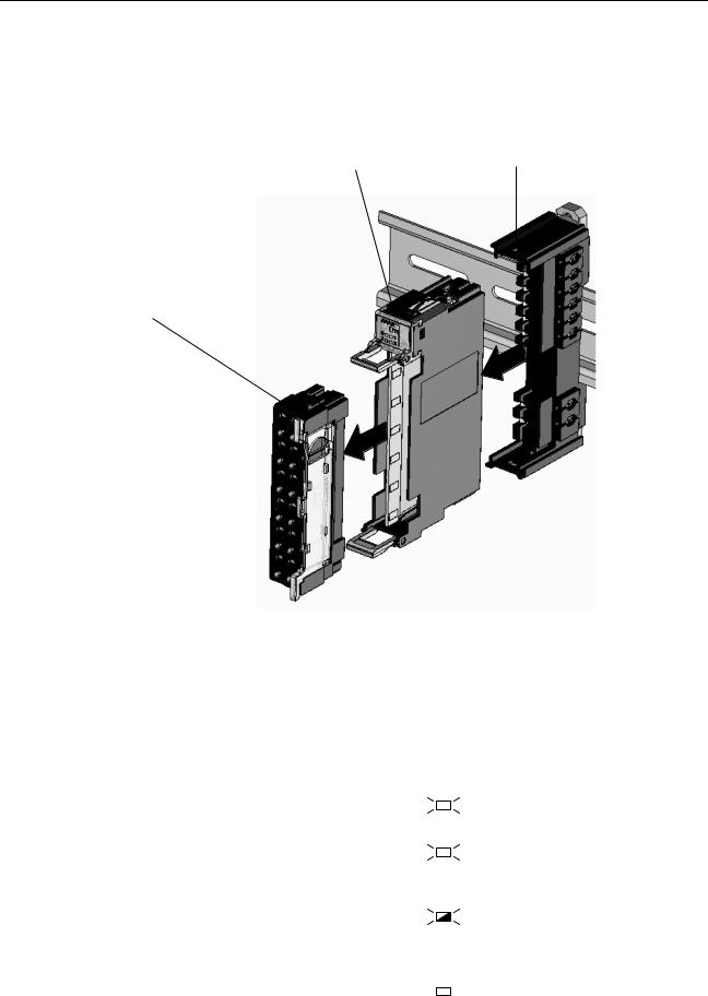
2-1 Nomenclature and Dimensions
Nomenclature
DeviceNet communications connector
Connect the DeviceNet network's communications cable to this connector.
Rotary switches
Set the Unit's node address as a DeviceNet Slave. Set a decimal node address between 0 and 63.
Indicators
Refer to 2-1-1 LED Indicators for details.
DIP Switch
Sets the I/O allocation method and registers the I/O Unit configuration information.
SW1 (REGS): Create/enable registration table. SW2 (I/O): Always OFF
SW3 (ADR): Automatic restore SW4 (BACK): Backup trigger
Unit power supply terminals
Connect the power supply for the Unit's internal circuits and the connected Slice I/O Units' internal circuits.
I/O power supply terminals
Connect the power supply for the connected Slice I/O Units' external I/O.
Dimensions (mm)
12
24
40
62
58
70
3
84
3
10
Nomenclature and Dimensions |
Section 2-1 |
Slice I/O Unit
Structure
The Slice I/O Unit is made up of three blocks, as shown in the following diagram. When replacement is necessary, individual blocks can be replaced.
Main Block
Terminal Block
This is the Slice I/O Unit's terminal block.
If a faulty Unit is being replaced, the wiring can be left attached and just the Main Block replaced.
Base Block
This is the Slice I/O Unit's bus connector. If a faulty Unit is being replaced, this
block can be left attached during online replacement.
Note Refer to the GRT1 Series Slice I/O Units Operation Manual (W455) for details such as Slice I/O Unit specifications and standard models.
2-1-1 LED Indicators
The DeviceNet Communications Unit’s LED indicators indicate the status of the Unit, the DeviceNet network, and communications between the Unit and Slice I/O Units.
Name |
Color |
Status |
Meaning |
||
|
|
|
|
|
|
MS |
Green |
|
MS |
Normal status (DeviceNet Communica- |
|
DeviceNet Communica- |
|
|
|
|
tions Unit operating normally) |
|
|
|
|
|
|
tions Unit status |
Red |
|
|
|
Non-recoverable, fatal error occurred. |
|
|
|
MS |
• Watchdog timer error |
|
|
|
|
|
|
|
|
|
|
|
|
• RAM error |
|
|
|
|
|
|
|
|
|
|
|
Recoverable, non-fatal error occurred. |
|
|
|
MS |
• EEPROM checksum error |
|
|
|
|
|
|
• Parameter setting logic error |
|
|
|
|
|
• EEPROM hardware error |
|
|
|
|
|
|
|
--- |
|
|
|
No power |
|
|
|
MS |
• The Unit’s power supply is OFF. |
|
|
|
|
|
|
• The Unit is being reset. |
|
|
|
|
|
|
|
|
|
|
|
• The Unit is waiting for initialization. |
|
|
|
|
|
|
11
Loading...