


Cat. No. W309-E1-07
SYSMAC CS1W-CLK21-V1 CJ1W-CLK21-V1 C200HW-CLK21 CVM1-CLK21 CQM1H-CLK21
(CS1W-RPT01/02/03 Repeater Units)
Controller Link Units
OPERATION MANUAL
CS1W-CLK21-V1
CJ1W-CLK21-V1
C200HW-CLK21 CVM1-CLK21 CQM1H-CLK21
(CS1W-RPT01/02/03 Repeater Units)
Controller Link Units
Operation Manual
Revised June 2003
iv
Notice:
OMRON products are manufactured for use according to proper procedures by a qualified operator and only for the purposes described in this manual.
The following conventions are used to indicate and classify precautions in this manual. Always heed the information provided with them. Failure to heed precautions can result in injury to people or damage to property.
!DANGER Indicates an imminently hazardous situation which, if not avoided, will result in death or serious injury.
!WARNING Indicates a potentially hazardous situation which, if not avoided, could result in death or serious injury.
!Caution Indicates a potentially hazardous situation which, if not avoided, may result in minor or moderate injury, or property damage.
OMRON Product References
All OMRON products are capitalized in this manual. The word “Unit” is also capitalized when it refers to an OMRON product, regardless of whether or not it appears in the proper name of the product.
The abbreviation “Ch,” which appears in some displays and on some OMRON products, often means “word” and is abbreviated “Wd” in documentation in this sense.
The abbreviation “PLC” means Programmable Controller. “PC” is used, however, in some Programming Device displays to mean Programmable Controller.
Visual Aids
The following headings appear in the left column of the manual to help you locate different types of information.
Note Indicates information of particular interest for efficient and convenient operation of the product.
1,2,3... 1. Indicates lists of one sort or another, such as procedures, checklists, etc.
OMRON, 1997
All rights reserved. No part of this publication may be reproduced, stored in a retrieval system, or transmitted, in any form, or by any means, mechanical, electronic, photocopying, recording, or otherwise, without the prior written permission of OMRON.
No patent liability is assumed with respect to the use of the information contained herein. Moreover, because OMRON is constantly striving to improve its high-quality products, the information contained in this manual is subject to change without notice. Every precaution has been taken in the preparation of this manual. Nevertheless, OMRON assumes no responsibility for errors or omissions. Neither is any liability assumed for damages resulting from the use of the information contained in this publication.
v
vi
TABLE OF CONTENTS
PRECAUTIONS . . . . . . . . . . . . . . . . . . . . . . . . . . . . . . . . . . . |
xiii |
|
1 |
Intended Audience . . . . . . . . . . . . . . . . . . . . . . . . . . . . . . . . . . . . . . . . . . . . . . . . . . . . . . . . |
xiv |
2 |
General Precautions . . . . . . . . . . . . . . . . . . . . . . . . . . . . . . . . . . . . . . . . . . . . . . . . . . . . . . . |
xiv |
3 |
Safety Precautions. . . . . . . . . . . . . . . . . . . . . . . . . . . . . . . . . . . . . . . . . . . . . . . . . . . . . . . . . |
xiv |
4 |
Operating Environment Precautions . . . . . . . . . . . . . . . . . . . . . . . . . . . . . . . . . . . . . . . . . . . |
xv |
5 |
Applications Precautions. . . . . . . . . . . . . . . . . . . . . . . . . . . . . . . . . . . . . . . . . . . . . . . . . . . . |
xvi |
6 Conformance to EC Directives . . . . . . . . . . . . . . . . . . . . . . . . . . . . . . . . . . . . . . . . . . . . . . . |
xviii |
|
SECTION 1 |
|
|
Features and System Configuration . . . . . . . . . . . . . . . . . . . |
1 |
|
1-1 |
Overview. . . . . . . . . . . . . . . . . . . . . . . . . . . . . . . . . . . . . . . . . . . . . . . . . . . . . . . . . . . . . . . . |
2 |
1-2 |
Specifications and Configurations . . . . . . . . . . . . . . . . . . . . . . . . . . . . . . . . . . . . . . . . . . . . |
11 |
1-3 Selection of Communications Functions . . . . . . . . . . . . . . . . . . . . . . . . . . . . . . . . . . . . . . . |
25 |
|
1-4 |
Basic Procedures . . . . . . . . . . . . . . . . . . . . . . . . . . . . . . . . . . . . . . . . . . . . . . . . . . . . . . . . . . |
26 |
1-5 |
Application Precautions . . . . . . . . . . . . . . . . . . . . . . . . . . . . . . . . . . . . . . . . . . . . . . . . . . . . |
27 |
SECTION 2 |
|
|
Basic Procedures. . . . . . . . . . . . . . . . . . . . . . . . . . . . . . . . . . . |
31 |
|
2-1 |
Data Links Procedures . . . . . . . . . . . . . . . . . . . . . . . . . . . . . . . . . . . . . . . . . . . . . . . . . . . . . |
32 |
2-2 |
Message Service Procedure . . . . . . . . . . . . . . . . . . . . . . . . . . . . . . . . . . . . . . . . . . . . . . . . . |
40 |
SECTION 3 |
|
|
Installation and Wiring . . . . . . . . . . . . . . . . . . . . . . . . . . . . . |
43 |
|
3-1 Component Names and Functions . . . . . . . . . . . . . . . . . . . . . . . . . . . . . . . . . . . . . . . . . . . . |
44 |
|
3-2 |
Unit Installation. . . . . . . . . . . . . . . . . . . . . . . . . . . . . . . . . . . . . . . . . . . . . . . . . . . . . . . . . . . |
58 |
3-3 |
Wiring . . . . . . . . . . . . . . . . . . . . . . . . . . . . . . . . . . . . . . . . . . . . . . . . . . . . . . . . . . . . . . . . . . |
65 |
3-4 Constructing Networks with Repeater Units . . . . . . . . . . . . . . . . . . . . . . . . . . . . . . . . . . . . |
77 |
|
SECTION 4 |
|
|
Preparations for Communications . . . . . . . . . . . . . . . . . . . . |
83 |
|
4-1 CS-series Controller Link Units . . . . . . . . . . . . . . . . . . . . . . . . . . . . . . . . . . . . . . . . . . . . . . |
84 |
|
4-2 CJ-series Controller Link Units . . . . . . . . . . . . . . . . . . . . . . . . . . . . . . . . . . . . . . . . . . . . . . |
87 |
|
4-3 C200HX/HG/HE Controller Link Units . . . . . . . . . . . . . . . . . . . . . . . . . . . . . . . . . . . . . . . . |
91 |
|
4-4 CVM1 and CV-series Controller Link Units. . . . . . . . . . . . . . . . . . . . . . . . . . . . . . . . . . . . . |
95 |
|
4-5 CQM1H-series Controller Link Units. . . . . . . . . . . . . . . . . . . . . . . . . . . . . . . . . . . . . . . . . . |
98 |
|
4-6 |
Repeater Units. . . . . . . . . . . . . . . . . . . . . . . . . . . . . . . . . . . . . . . . . . . . . . . . . . . . . . . . . . . . |
100 |
vii
TABLE OF CONTENTS
SECTION 5 |
|
|
Data Links . . . . . . . . . . . . . . . . . . . . . . . . . . . . . . . . . . . . . . . . |
103 |
|
5-1 What Are Data Links? . . . . . . . . . . . . . . . . . . . . . . . . . . . . . . . . . . . . . . . . . . . . . . . . . . . . . . |
104 |
|
5-2 |
Setting Data Links . . . . . . . . . . . . . . . . . . . . . . . . . . . . . . . . . . . . . . . . . . . . . . . . . . . . . . . . . |
110 |
5-3 Starting and Stopping Data Links . . . . . . . . . . . . . . . . . . . . . . . . . . . . . . . . . . . . . . . . . . . . . |
150 |
|
5-4 Checking Data Link Status . . . . . . . . . . . . . . . . . . . . . . . . . . . . . . . . . . . . . . . . . . . . . . . . . . |
153 |
|
SECTION 6 |
|
|
Message Service. . . . . . . . . . . . . . . . . . . . . . . . . . . . . . . . . . . . |
163 |
|
6-1 |
Introduction . . . . . . . . . . . . . . . . . . . . . . . . . . . . . . . . . . . . . . . . . . . . . . . . . . . . . . . . . . . . . . |
164 |
6-2 |
Selecting Communications Instructions . . . . . . . . . . . . . . . . . . . . . . . . . . . . . . . . . . . . . . . . |
184 |
6-3 Using the Message Service . . . . . . . . . . . . . . . . . . . . . . . . . . . . . . . . . . . . . . . . . . . . . . . . . . |
187 |
|
6-4 FINS Commands and Responses. . . . . . . . . . . . . . . . . . . . . . . . . . . . . . . . . . . . . . . . . . . . . . |
197 |
|
6-5 Commands and Responses for Controller Link Units . . . . . . . . . . . . . . . . . . . . . . . . . . . . . . |
199 |
|
6-6 Commands and Responses for C200HX/HG/HE and CQM1H-series PLCs . . . . . . . . . . . . |
210 |
|
6-7 |
Response Codes. . . . . . . . . . . . . . . . . . . . . . . . . . . . . . . . . . . . . . . . . . . . . . . . . . . . . . . . . . . |
223 |
SECTION 7 |
|
|
Network Interconnections . . . . . . . . . . . . . . . . . . . . . . . . . . . |
231 |
|
7-1 What is Network Interconnection? . . . . . . . . . . . . . . . . . . . . . . . . . . . . . . . . . . . . . . . . . . . . |
232 |
|
7-2 Remote Programming and Monitoring . . . . . . . . . . . . . . . . . . . . . . . . . . . . . . . . . . . . . . . . . |
234 |
|
7-3 |
Routing Tables . . . . . . . . . . . . . . . . . . . . . . . . . . . . . . . . . . . . . . . . . . . . . . . . . . . . . . . . . . . . |
237 |
7-4 |
Setting Routing Tables. . . . . . . . . . . . . . . . . . . . . . . . . . . . . . . . . . . . . . . . . . . . . . . . . . . . . . |
238 |
SECTION 8 |
|
|
Communications Timing . . . . . . . . . . . . . . . . . . . . . . . . . . . . |
245 |
|
8-1 |
Communications Mechanism . . . . . . . . . . . . . . . . . . . . . . . . . . . . . . . . . . . . . . . . . . . . . . . . |
246 |
8-2 |
Communications Cycle Time . . . . . . . . . . . . . . . . . . . . . . . . . . . . . . . . . . . . . . . . . . . . . . . . |
249 |
8-3 Data Link I/O Response Time . . . . . . . . . . . . . . . . . . . . . . . . . . . . . . . . . . . . . . . . . . . . . . . . |
251 |
|
8-4 |
Message Delay Times . . . . . . . . . . . . . . . . . . . . . . . . . . . . . . . . . . . . . . . . . . . . . . . . . . . . . . |
263 |
SECTION 9 |
|
|
Troubleshooting and Maintenance . . . . . . . . . . . . . . . . . . . . |
271 |
|
9-1 |
Troubleshooting Using Indicators . . . . . . . . . . . . . . . . . . . . . . . . . . . . . . . . . . . . . . . . . . . . . |
272 |
9-2 Status Area and Troubleshooting. . . . . . . . . . . . . . . . . . . . . . . . . . . . . . . . . . . . . . . . . . . . . . |
288 |
|
9-3 |
Error Log . . . . . . . . . . . . . . . . . . . . . . . . . . . . . . . . . . . . . . . . . . . . . . . . . . . . . . . . . . . . . . . . |
309 |
9-4 |
Cleaning and Inspection . . . . . . . . . . . . . . . . . . . . . . . . . . . . . . . . . . . . . . . . . . . . . . . . . . . . |
316 |
9-5 |
Handling Precautions. . . . . . . . . . . . . . . . . . . . . . . . . . . . . . . . . . . . . . . . . . . . . . . . . . . . . . . |
317 |
viii
TABLE OF CONTENTS
SECTION 10
Adding Nodes and Editing Active Data Link Tables . . . . . 323
10-1 |
Adding Nodes Using a Repeater Unit. . . . . . . . . . . . . . . . . . . . . . . . . . . . . . . . . . . . . . . . . . |
324 |
10-2 |
Changing the Data Link Tables with Active Data Links . . . . . . . . . . . . . . . . . . . . . . . . . . . |
328 |
Appendices
A Standard Models . . . . . . . . . . . . . . . . . . . . . . . . . . . . . . . . . . . . . . . . . . . . . . . . . . . . . . . . . . |
335 |
|
B |
Memory Areas . . . . . . . . . . . . . . . . . . . . . . . . . . . . . . . . . . . . . . . . . . . . . . . . . . . . . . . . . . . |
339 |
C |
Using the Relay Terminal Block . . . . . . . . . . . . . . . . . . . . . . . . . . . . . . . . . . . . . . . . . . . . . |
357 |
Index . . . . . . . . . . . . . . . . . . . . . . . . . . . . . . . . . . . . . . . . . . . . |
361 |
|
Revision History . . . . . . . . . . . . . . . . . . . . . . . . . . . . . . . . . . . |
365 |
|
ix
TABLE OF CONTENTS
x
About this Manual:
This manual describes the installation, setup, and operation of the C200HW-CLK21, CS1W-CLK21- V1, CJ1W-CLK21-V1, CVM1-CLK21, and CQM1H-CLK21 Controller Link Units for C200HX/HG/HE, CS/CJ-series, CVM1, CQM1H-series, and CV-series PLCs, and includes the sections described below. The Controller Link Units are used to connect these PLCs to a Controller Link Network. Information is also provided in this manual on CS1W-RPT01/02/03 Repeater Units. The following three manuals are directly related to application of the Controller Link Network.
Name |
Contents |
Cat. No. |
|
|
(suffixes omitted) |
|
|
|
SYSMAC CS1W-CLK21, CJ1W-CLK21, |
Installation, setup, and operating procedures for the Con- |
W309 |
C200HW-CLK21, CVM1-CLK21. |
troller Link Units. Controller Link Units are used to connect |
|
CQM1H-CLK21 Controller Link Units |
PLCs to a Controller Link Network. |
|
Operation Manual (this manual) |
|
|
|
|
|
3G8F7-CLK12-E-V1/CLK52-E-V1/ |
Operating procedures for Controller Link Support Boards |
W383 |
CLK21-E-V1 Controller Link Support |
for PCI bus connections. Controller Link Support Boards |
|
Boards for PCI Bus |
are used to connect IBM PC/ATs or compatibles to a Con- |
|
Operation Manual |
troller Link Network. |
|
|
|
|
3G8F7-CLK12-E/CLK52-E/CLK21-E Con- |
Installation and setup procedures for Controller Link Sup- |
W388 |
troller Link Support Boards for PCI Bus |
port Boards for PCI bus connections. Controller Link Sup- |
|
Installation Guide |
port Boards are used to connect IBM PC/ATs or |
|
|
compatibles to a Controller Link Network. |
|
|
|
|
3G8F5-CLK11-E, 3G8F5-CLK21-E Con- |
Installation, setup, and operating procedures for Controller |
W307 |
troller Link Support Boards for ISA Bus |
Link Support Boards for ISA bus connections. Controller |
|
Operation Manual |
Link Support Boards are used to connect IBM PC/ATs or |
|
|
compatibles to a Controller Link Network. |
|
|
|
|
CS1W-CLK12, CVM1-CLK12 Optical |
Installation, setup, and operating procedures for the Optical |
W370 |
Ring Controller Link Units |
Ring Controller Link Units. Controller Link Units are used to |
|
Operation Manual |
connect C200HX/HG/HE CV-series, and CS1-series PLCs |
|
|
to a Controller Link Network. |
|
|
|
|
C200HW-ZW3AT2-E-V2 Controller Link |
Installation and operating procedures for the Controller |
W369 |
Support Software |
Link Support Software. The Controller Link Support Soft- |
|
Operation Manual |
ware enables manually set data links and other procedures |
|
|
for a Controller Link Network. |
|
|
|
|
Depending on the system, you may also need the SYSMAC or CV Support Software, the CX-Program- mer, or a Programming Console. Refer to the body of this manual for details. Please read this manual and related manuals carefully and be sure you understand the information provided before attempting to install and operate a Controller Link Unit.
Precautions provides general precautions for using the Controller Link Unit and related devices. Section 1 provides basic information on Controller Link Networks, and will give the reader an overview of what Controller Link Networks can do and how best to use them.
Section 2 describes the basic procedures to use the Controller Link Unit. The settings necessary for using each of the functions are also explained briefly. For more details, refer to the following sections on individual functions.
Section 3 describes how to install a Controller Link Unit and how to wire the Controller Link Network. Details are also provided on installation, wiring, and basic operating procedures of Repeater Units, including information on using them to construct networks.
Section 4 describes the settings required for starting communications. These basic settings are required for both data links function and the message service. Carry out the settings described here before turning on power to the Controller Link Unit.
Section 5 describes how to use data links in a Controller Link Network. Refer to SECTION 2 Basic Procedures for an outline of data link application.
Section 6 explains how to use the message service provided by a Controller Link Unit. It also explains the FINS commands and responses supported by Controller Link Units and those supported by C200HX/HG/HE, CVM1, and CV-series PLCs.
xi
Section 7 describes the method used to connect multiple networks through CS/CJ-series, CVM1, and CV-series PLCs. The section also describes remote programming and monitoring with Programming Devices.
Section 8 explains details on Controller Link Network communications. Refer to this section for network communications that require accurate communications timing.
Section 9 provides information on troubleshooting errors that occur during Controller Link Unit operation, as well as daily inspection, cleaning, and other maintenance procedures.
Section 10 provides information on functions that can be performed without turning OFF the PLC power to the existing network, such as adding nodes to the Controller Link Network using a Repeater Unit and changing data link tables while the data links are active.
Appendix A provides a list of standard OMRON products related to Controller Link Networks. Appendix B provides easy reference to the words in PLC memory areas used by Controller Link Networks.
Appendix C provides information on how to use the CJ1W-TB101 Wired Controller Link Unit Relay Terminal Block, including details on connection and replacement.
!WARNING |
Failure to read and understand the information provided in this manual may |
|
result in personal injury or death, damage to the product, or product failure. |
|
Please read each section in its entirety and be sure you understand the infor- |
|
mation provided in the section and related sections before attempting any of |
|
the procedures or operations given. |
|
|
xii
PRECAUTIONS
This section provides general precautions for using the Controller Link Unit and related devices.
The information contained in this section is important for the safe and reliable application of the Controller Link Unit. You must read this section and understand the information contained before attempting to set up or operate a Controller Link Unit.
1 |
Intended Audience . . . . . . . . . . . . . . . . . . . . . . . . . . . . . . . . . . . . . . . . . . . . . |
xiv |
2 |
General Precautions . . . . . . . . . . . . . . . . . . . . . . . . . . . . . . . . . . . . . . . . . . . . |
xiv |
3 |
Safety Precautions. . . . . . . . . . . . . . . . . . . . . . . . . . . . . . . . . . . . . . . . . . . . . . |
xiv |
4 |
Operating Environment Precautions . . . . . . . . . . . . . . . . . . . . . . . . . . . . . . . . |
xv |
5 |
Applications Precautions. . . . . . . . . . . . . . . . . . . . . . . . . . . . . . . . . . . . . . . . . |
xvi |
6 |
Conformance to EC Directives . . . . . . . . . . . . . . . . . . . . . . . . . . . . . . . . . . . . |
xviii |
xiii

Intended Audience |
1 |
1 Intended Audience
This manual is intended for the following personnel, who must also have knowledge of electrical systems (an electrical engineer or the equivalent).
•Personnel in charge of installing FA systems.
•Personnel in charge of designing FA systems.
•Personnel in charge of managing FA systems and facilities.
2 General Precautions
The user must operate the product according to the performance specifications described in the operation manuals.
Before using the product under conditions which are not described in the manual or applying the product to nuclear control systems, railroad systems, aviation systems, vehicles, combustion systems, medical equipment, amusement machines, safety equipment, and other systems, machines, and equipment that may have a serious influence on lives and property if used improperly, consult your OMRON representative.
Make sure that the ratings and performance characteristics of the product are sufficient for the systems, machines, and equipment, and be sure to provide the systems, machines, and equipment with double safety mechanisms.
This manual provides information for programming and operating OMRON PLCs and related devices. Be sure to read this manual before attempting to use the software and keep this manual close at hand for reference during operation.
!WARNING It is extremely important that a PLC and all PLC Units be used for the specified purpose and under the specified conditions, especially in applications that can directly or indirectly affect human life. You must consult with your OMRON representative before applying a PLC System to the above mentioned applications.
3 Safety Precautions
!WARNING Do not attempt to take any Unit apart while the power is being supplied. Doing so may result in electric shock.
!WARNING Do not touch any of the terminals or terminal blocks while the power is being supplied. Doing so may result in electric shock.
!WARNING Provide safety measures in external circuits (i.e., not in the Programmable Controller), including the following items, to ensure safety in the system if an abnormality occurs due to malfunction of the PLC or another external factor affecting the PLC operation. Not doing so may result in serious accidents.
•Fail-safe measures must be taken by the customer to ensure safety in the event of incorrect, missing, or abnormal signals caused by broken signal lines, momentary power interruptions, or other causes.
•Emergency stop circuits, interlock circuits, limit circuits, and similar safety measures must be provided in external control circuits.
xiv

Operating Environment Precautions |
4 |
•The PLC will turn OFF all outputs when its self-diagnosis function detects any error or when a severe failure alarm (FALS) instruction is executed. As a countermeasure for such errors, external safety measures must be provided to ensure safety in the system.
•The PLC outputs may remain ON or OFF due to deposition or burning of the output relays or destruction of the output transistors. As a countermeasure for such problems, external safety measures must be provided to ensure safety in the system.
•When the 24-VDC output (service power supply to the PLC) is overloaded or short-circuited, the voltage may drop and result in the outputs being turned OFF. As a countermeasure for such problems, external safety measures must be provided to ensure safety in the system.
!Caution Execute online edit only after confirming that no adverse effects will be caused by extending the cycle time. Otherwise, the input signals may not be readable.
!Caution Confirm safety at the destination node before transferring a program to another node or changing contents of the I/O memory area. Doing either of these without confirming safety may result in injury.
4 Operating Environment Precautions
!Caution Do not operate the control system in the following locations:
•Locations subject to direct sunlight.
•Locations subject to temperatures or humidity outside the range specified in the specifications.
•Locations subject to condensation as the result of severe changes in temperature.
•Locations subject to corrosive or flammable gases.
•Locations subject to dust (especially iron dust) or salts.
•Locations subject to exposure to water, oil, or chemicals.
•Locations subject to shock or vibration.
!Caution Take appropriate and sufficient countermeasures when installing systems in the following locations:
•Locations subject to static electricity or other forms of noise.
•Locations subject to strong electromagnetic fields.
•Locations subject to possible exposure to radioactivity.
•Locations close to power supplies.
!Caution The operating environment of the PLC System can have a large effect on the longevity and reliability of the system. Improper operating environments can lead to malfunction, failure, and other unforeseeable problems with the PLC System. Be sure that the operating environment is within the specified conditions at installation and remains within the specified conditions during the life of the system.
xv

Applications Precautions |
5 |
5 Applications Precautions
Observe the following precautions when using the Controller Link Unit.
!WARNING Failure to abide by the following precautions could lead to serious or possibly fatal injury. Always heed these precautions.
•Always ground the system to 100 Ω or less when installing the system to protect against electrical shock.
•Always turn OFF the power supply or the backup power supply to the PLC or the computer before attempting any of the following. Performing any of the following with the power supply turned ON may lead to electrical shock:
•Installing or removing the Controller Link Unit.
•Assembling the Units.
•Setting DIP or rotary switches.
•Connecting or disconnecting any cables or wiring.
•Connecting or disconnecting any terminal block.
!Caution Failure to abide by the following precautions could lead to faulty operation or the PLC or the system or could damage the PLC or PLC Units. Always heed these precautions.
•Always use the power supply voltages specified in the operation manuals. An incorrect voltage may result in malfunction or burning.
•Take appropriate measures to ensure that the specified power with the rated voltage and frequency is supplied. Be particularly careful in places where the power supply is unstable. An incorrect power supply may result in malfunction.
•Install external breakers and take other safety measures against short-cir- cuiting in external wiring. Insufficient safety measures against short-cir- cuiting may result in burning.
•Disconnect the functional ground terminal when performing withstand voltage tests. Not disconnecting the functional ground terminal may result in burning.
•Do not attempt to disassemble, repair, or modify any Units. Any attempt to do so may result in malfunction, fire, or electric shock.
•Install the Units properly as specified in the operation manuals. Improper installation of the Units may result in malfunction.
•Be sure that all the mounting screws, terminal screws, and cable connector screws are tightened to the torque specified in the relevant manuals. Incorrect tightening torque may result in malfunction.
•Leave the label attached to the Unit when wiring. Removing the label may result in malfunction if foreign matter enters the Unit.
•Remove the label after the completion of wiring to ensure proper heat dissipation. Leaving the label attached may result in malfunction.
•Use crimp terminals for wiring. Do not connect bare stranded wires directly to terminals. Connection of bare stranded wires may result in burning.
xvi

Applications Precautions |
5 |
•Double-check all wiring and switch settings before turning ON the power supply. Incorrect wiring may result in burning.
•Wire all connections correctly.
•Mount Units only after checking terminal blocks completely.
•Be sure that the Bus Connection Units and other items with locking devices are properly locked into place. Improper locking may result in malfunction.
•Use special packing box when transporting the Controller Link Unit. Handle the product carefully so that no excessive vibration or impact is applied to the product during transportation.
•Check the user program for proper execution before actually running it on the Unit. Not checking the program may result in an unexpected operation.
•Confirm that no adverse effect will occur in the system before attempting any of the following. Not doing so may result in an unexpected operation.
•Changing the operating mode of the PLC.
•Force-setting/force-resetting any bit in memory.
•Changing the present value of any word or any set value in memory.
•Inappropriate settings in data link tables or routing tables can cause unexpected system operation. Always check table settings before starting operation, and always test the settings in trial operation before starting or stopping the data links in actual operation.
•CPU Bus Units will be automatically restarted when routing tables are transferred from a Programming Device to the CPU Unit. Resetting is required to use the new tables. Confirm that restarting the CPU Bus Units will not adversely affect system operation before transferring routing tables.
•Observe the following precautions when wiring the communications cables.
•Separate the cables from the power lines or high-tension lines.
•Do not bend the cables.
•Do not pull on the cables.
•Do not place heavy objects on top of the cables.
•Route cables inside conduits.
•Before touching the Unit, be sure to first touch a grounded metallic object in order to discharge any static build-up.
xvii

Conformance to EC Directives |
6 |
6 Conformance to EC Directives
The Controller Link Units conform to EMC and Low Voltage Directives as follows:
EMC Directives
OMRON devices that comply with EC Directives also conform to the related EMC standards so that they can be more easily built into other devices or the overall machine. The actual products have been checked for conformity to EMC standards (see the following note). Whether the products conform to the standards in the system used by the customer, however, must be checked by the customer.
EMC-related performance of the OMRON devices that comply with EC Directives will vary depending on the configuration, wiring, and other conditions of the equipment or control panel on which the OMRON devices are installed. The customer must, therefore, perform the final check to confirm that devices and the overall machine conform to EMC standards.
Note Applicable EMS (Electro-Magnetic Susceptibility) and EMI (Electro-Magnetic Interference) standards in the EMC (Electro-Magnetic Compatibility) standards are as follows:
|
EMS |
EMI |
|
|
|
CQM1H-CLK21 |
EN61131-2 |
EN50081-2 |
C200HW-CLK21 |
|
|
|
|
|
CVM1-CLK21 |
|
EN61000-6-4 |
CS1W-CLK21(-V1) |
|
|
|
|
|
CJ1W-CLK21(-V1) |
EN61000-6-2 |
|
|
|
|
Low Voltage Directive
Always ensure that devices operating at voltages of 50 to 1,000 VAC and 75 to 1,500 VDC meet the required safety standards for the PLC (EN61131-2).
The Controller Link Units that comply with EC Directives (CVM1-CLK21,
C200HW-CLK21, CS1W-CLK21(-V1), CJ1W-CLK21(-V1), and CQM1H-
CLK21) must be installed as follows:
1,2,3... 1. The Controller Link Units are designed for installation inside control panels. All Controller Link Units must be installed within control panels.
2.Use reinforced insulation or double insulation for the DC power supplies used for the communications power supply and I/O power supplies.
3.The Controller Link Units that comply with EC Directives also conform to the Common Emission Standard (EN50081-2 or EN61000-6-4). Radiated emission characteristics (10-m regulations) may vary depending on the configuration of the control panel used, other devices connected to the control panel, wiring, and other conditions. You must therefore confirm that the overall machine or equipment complies with EC Directives.
xviii
SECTION 1
Features and System Configuration
This section provides basic information on Controller Link Networks, and will give the reader an overview of what Controller Link Networks can do and how best to use them.
1-1 |
Overview. . . . . . . . . . . . . . . . . . . . . . . . . . . . . . . . . . . . . . . . . . . . . . . . . . . . . |
2 |
|
|
1-1-1 What Is the Controller Link? . . . . . . . . . . . . . . . . . . . . . . . . . . . . . . |
2 |
|
|
1-1-2 |
Features. . . . . . . . . . . . . . . . . . . . . . . . . . . . . . . . . . . . . . . . . . . . . . . |
8 |
1-2 |
Specifications and Configurations . . . . . . . . . . . . . . . . . . . . . . . . . . . . . . . . . |
11 |
|
|
1-2-1 |
System Configuration . . . . . . . . . . . . . . . . . . . . . . . . . . . . . . . . . . . . |
11 |
|
1-2-2 |
General Specifications . . . . . . . . . . . . . . . . . . . . . . . . . . . . . . . . . . . |
13 |
|
1-2-3 |
Communications Specifications . . . . . . . . . . . . . . . . . . . . . . . . . . . . |
14 |
|
1-2-4 Controller Link Unit Models and PLCs . . . . . . . . . . . . . . . . . . . . . . |
16 |
|
|
1-2-5 |
Devices for Connection . . . . . . . . . . . . . . . . . . . . . . . . . . . . . . . . . . |
18 |
|
1-2-6 |
Programming Devices . . . . . . . . . . . . . . . . . . . . . . . . . . . . . . . . . . . |
21 |
1-3 Selection of Communications Functions . . . . . . . . . . . . . . . . . . . . . . . . . . . . |
25 |
||
1-4 |
Basic Procedures . . . . . . . . . . . . . . . . . . . . . . . . . . . . . . . . . . . . . . . . . . . . . . . |
26 |
|
1-5 |
Application Precautions . . . . . . . . . . . . . . . . . . . . . . . . . . . . . . . . . . . . . . . . . |
27 |
|
1

Overview |
Section 1-1 |
1-1 Overview
1-1-1 What Is the Controller Link?
The Controller Link is an FA network that can send and receive large data packets flexibly and easily among the OMRON C200HX/HG/HE Programmable Controllers (PLCs), CS-series PLCs, CJ-series PLCs, CVM1 PLCs, CVseries PLCs, CQM1H-series PLCs, and IBM PC/AT or compatible computers.
The Controller Link supports data links that enable data sharing and a message service that enables sending and receiving data when required. Data link areas can be freely set to create a flexible data link system and effectively use data areas.
High-volume data transmissions are possible at high speed and so a wide range of networks, from low-level systems to high, can be easily created.
There are two types of networks: networks connected with shielded twistedpair cable and networks connected with optical fiber cable. Using a Repeater Unit in networks connected with twisted-pair cable makes it possible to use a variety of different wiring configurations, such as T-branch wiring, long-dis- tance wiring, and partial conversion to optical fiber. (Refer to the CS1WCLK12, CVM1-CLK12 Optical Ring Controller Link Units Operation Manual
(W370) for detail on optical fiber connections.)
The functions of a Controller Link Network are illustrated below.
|
|
|
|
|
|
|
|
|
|
|
|
|
|
Controller Link |
|
|
|
|
Data link |
|
|
|
|
|
Manual settings |
|
||||||||||||||||
|
|
|
|
|
|
|
|
|
|
|
|
|
|
|
|
|
|
|
|
|
|
|||||||||||||||||||||
|
|
|
|
|
|
|
|
|
|
|
|
|
|
|
|
|
|
|
|
|
|
|
|
|
|
|
|
|
|
|
|
|
|
|
|
|
|
|
|
|
|
|
|
|
|
|
|
|
|
|
|
|
|
|
|
|
|
|
|
|
|
|
|
|
|
|
|
|
|
|
|
|
|
|
|
|
|
|
|
|
|
|
|
||
|
|
|
|
|
|
|
|
|
|
|
|
|
|
|
|
|
|
|
|
|
|
|
|
|
|
|
|
|
|
|
|
|
|
Automatic settings |
|
|||||||
|
|
|
|
|
|
|
|
|
|
|
|
|
|
|
|
|
|
|
|
|
|
|
|
|
|
|
|
|
|
|
|
|
|
|||||||||
|
|
|
|
|
|
|
|
|
|
|
|
|
|
|
|
|
|
|
|
|
|
|
|
|
|
|
|
|
|
|
|
|
|
|
|
|
|
|
|
|
||
|
|
|
|
|
|
|
|
|
|
|
|
|
|
|
|
|
|
|
|
|
|
|
|
|
|
|
|
|
|
|
|
|
|
|
|
|
|
|
|
|
|
|
|
|
|
|
|
|
|
|
|
|
|
|
|
|
|
|
|
|
|
|
|
|
|
|
Message service |
|
|
|
|
SEND/RECV instructions |
|
||||||||||||
|
|
|
|
|
|
|
|
|
|
|
|
|
|
|
|
|
|
|
|
|
|
|
|
|
|
|
||||||||||||||||
|
|
|
|
|
|
|
|
|
|
|
|
|
|
|
|
|
|
|
|
|
|
|
|
|
|
|
|
|
|
|
|
|
|
|
|
|
|
|
|
|
|
|
|
|
|
|
|
|
|
|
|
|
|
|
|
|
|
|
|
|
|
|
|
|
|
|
|
|
|
|
|
|
|
|
|
|
|
|
|
|
|
|
|
||
|
|
|
|
|
|
|
|
|
|
|
|
|
|
|
|
|
|
|
|
|
|
|
|
|
|
|
|
|
|
|
|
|
|
CMND instruction |
|
|||||||
|
|
|
|
|
|
|
|
|
|
|
|
|
|
|
|
|
|
|
|
|
|
|
|
|
|
|
|
|
|
|
|
|
|
|||||||||
|
|
|
|
|
|
|
|
|
|
|
|
|
|
|
|
|
|
|
|
|
|
|
|
|
|
|
|
|
|
|
|
|
|
|
|
|
|
|
|
|
|
|
|
|
|
|
|
|
|
|
|
|
|
|
|
|
|
|
|
|
|
|
|
|
|
|
|
|
|
|
|
|
|
|
|
|
|
|
|
|
|
|
|
|
|
|
|
|
|
|
|
|
|
|
|
|
|
|
|
|
|
|
|
|
|
|
|
|
|
RAS functions |
|
|
|
|
|
Status area function |
|
|||||||||||
|
|
|
|
|
|
|
|
|
|
|
|
|
|
|
|
|
|
|
|
|
|
|
|
|
|
|
|
|||||||||||||||
|
|
|
|
|
|
|
|
|
|
|
|
|
|
|
|
|
|
|
|
|
|
|
|
|
|
|
|
|
|
|
|
|
|
|
|
|
|
|
|
|
|
|
|
|
|
|
|
|
|
|
|
|
|
|
|
|
|
|
|
|
|
|
|
|
|
|
|
|
|
|
|
|
|
|
|
|
|
|
|
|
|
|
|
||
|
|
|
|
|
|
|
|
|
|
|
|
|
|
|
|
|
|
|
|
|
|
|
|
|
|
|
|
|
|
|
|
|
|
Error log function |
|
|||||||
|
|
|
|
|
|
|
|
|
|
|
|
|
|
|
|
|
|
|
|
|
|
|
|
|
|
|
|
|
|
|
|
|
|
|||||||||
|
|
|
|
|
|
|
|
|
|
|
|
|
|
|
|
|
|
|
|
|
|
|
|
|
|
|
|
|
|
|
|
|
|
|
|
|
|
|
|
|
|
|
|
|
|
|
|
|
|
|
|
|
|
|
|
|
|
|
|
|
|
|
|
|
|
|
|
|
|
|
|
|
|
|
|
|
|
|
|
|
|
|
|
||
Wired System |
|
|
|
|
|
|
|
|
|
|
|
|
|
|
|
|
|
|
|
|
|
|
|
|
|
|
|
Polling node backup |
|
|||||||||||||
|
|
|
|
|
|
|
|
|
|
|
|
|
|
|
|
|
|
|
|
|
|
|
|
|
|
|
||||||||||||||||
|
|
|
|
|
|
|
|
|
|
|
|
|
|
|
|
|
|
|
|
|
|
|
|
|
|
|
|
|
|
|
||||||||||||
|
|
|
|
|
|
CS-series, CJ-series, C200HX/HG/HE, CVM1, CV-series, and CQM1H-series |
||||||||||||||||||||||||||||||||||||
(Twisted-pair Cable) |
|
PLCs |
|
|
|
|
|
|
|
|
|
|
|
|
|
|
|
|
|
|
|
|
|
|
|
|
|
|
|
|
|
|||||||||||
|
CS1W-CLK21-V1 |
|
CJ1W-CLK21-V1 |
C200HW-CLK21 |
CVM1-CLK21 |
|
|
CQM1H-CLK21 |
IBM PC/AT or |
|||||||||||||||||||||||||||||||||
|
Controller Link Unit |
Controller Link Unit |
Controller Link Unit |
Controller Link Unit |
Controller Link Unit |
compatible |
||||||||||||||||||||||||||||||||||||
CS-series |
CJ-series PLC |
|
C200HX/HG/HE |
CVM1, CV-series |
CQM1H-series |
|
|
|
|
|||||||||||||||||||||||||||||||||
PLC |
|
PLC |
|
|
|
|
|
|
PLC |
|
|
|
|
|
|
|
PLC |
|
|
|
|
|
|
|
|
|
|
|
|
|||||||||||||
|
|
|
|
|
|
|
|
|
|
|
|
|
|
|
|
|
|
|
|
|
|
|
|
|
|
|
|
|
|
|
|
|
|
|
|
|||||||
|
|
|
|
|
C |
|
|
|
|
|
|
C |
|
|
|
|
|
C |
|
|
|
|
|
|
|
|
C |
|
|
|
|
|
|
C |
|
|
|
|
|
|
|
|
|
|
|
|
|
|
|
|
|
|
|
|
|
|
|
|
|
|
|
|
|
|
|
|
|
|
|
|
|
|
|
||||||||||||
|
|
|
|
|
P |
|
|
|
|
|
|
P |
|
|
|
|
|
P |
|
|
|
|
|
|
|
|
P |
|
|
|
|
|
|
P |
|
|
|
|
|
|
|
|
|
|
|
|
|
U |
|
|
|
|
|
|
U |
|
|
|
|
|
U |
|
|
|
|
|
|
|
|
U |
|
|
|
|
|
|
U |
|
|
|
|
|
|
|
|
|
|
|
|
|
|
|
|
|
|
|
|
|
|
|
|
|
|
|
|
|
|
|
|
|
|
|
|
|
|
|
|
|
|
|
|
|
|
|
|
|
|
|
Twisted-pair cable
3G8F7-CLK21-E-V1 Controller Link Support Board
2

Overview |
|
|
|
|
|
|
Section 1-1 |
|||||||||
Connecting Repeater Units Using Twisted-pair Cable (Wired Units) |
||||||||||||||||
T-Branch Wiring |
|
|
|
|
|
|
|
|
||||||||
Wired Controller Link Unit |
|
Wired Controller Link Unit |
||||||||||||||
|
|
|
|
|
CS1W-RPT01 |
|
|
|
|
|
|
|
|
|||
|
|
|
|
|
|
|
|
|
|
|
|
|
||||
|
|
|
|
|
Repeater Units |
|
|
|
|
|
|
|
|
|||
|
|
|
|
Twisted-pair cable |
||||||||||||
|
|
|
|
|
|
|
|
|
||||||||
|
|
|
|
|
|
|
|
|
|
|
|
|
|
|
|
|
Twisted-pair cable
Long-distance Wiring
Wired Controller Link Unit
|
|
|
|
|
|
|
|
|
|
|
|
|
|
|
|
|
|
|
|
|
|
|
|
|
|
|
|
|
|
|
|
|
|
Twisted-pair cable |
CS1W-RPT01 |
|
|
|
|
|
|
|
|
|
|
|
|||||||||||
|
|
|
|
|
|
|
|
|
|
|
|
|
|
|
|
|
|
|
|
|
|
|
|
|||||
|
|
|
|
|
|
|
|
|
|
|
|
|
Repeater Units |
|
|
|
|
|
|
|
|
|
|
|
||||
|
|
|
|
|
500 m max. |
|
|
|
|
|
|
|
|
|
|
|
|
|
|
|
||||||||
|
|
|
|
|
|
|
|
|
|
|
|
|
|
|
|
|
|
|
|
|
|
|
|
|
||||
|
|
|
|
|
(See note.) |
|
|
|
|
|
|
|
|
|
|
|
|
|
|
|
|
|
|
|
|
|||
|
|
|
|
|
|
|
|
|
|
|
|
Twisted-pair |
|
|
|
|
|
|
|
|
|
|
|
|||||
|
|
|
|
|
|
|
|
|
|
|
|
cable |
|
Wired Controller Link Unit |
||||||||||||||
|
|
|
|
|
|
|
|
|
|
|
|
|
|
|
|
|
|
|
|
|
|
|
|
|
|
|
|
|
|
|
|
|
|
|
|
|
|
|
|
500 m max. |
|
|
|
|
|
|
|
|
|
|
|
|
|
|
|||
|
|
|
|
|
|
|
|
|
|
|
|
|
|
|
|
|
|
|
|
|
|
|
|
|
||||
|
|
|
|
|
|
|
|
|
|
|
(See note.) |
|
|
|
|
|
|
|
|
|
|
|
|
|
|
|||
|
|
|
|
|
|
|
|
|
|
|
|
|
|
|
|
|
|
|
|
|
|
|
|
|
|
|
|
|
|
|
|
|
|
|
|
|
|
|
|
|
|
|
|
|
|
|
|
|
|
|
|
|
|
|
|
|
|
|
|
|
|
|
|
|
|
|
|
|
|
|
|
|
|
|
|
Twisted-pair cable |
||||||||||
|
|
|
|
|
|
|
|
|
|
|
|
|
|
|
|
|
|
|
|
|
|
|
|
|||||
|
|
|
|
|
|
|
|
|
|
|
|
|
|
|
|
|
500 m max. (See note.) |
|||||||||||
|
|
|
|
|
|
|
|
|
|
|
|
|
|
|
|
|
|
|
|
|
|
|
Note: At 2 Mbit/s |
|||||
Converting Part of the Transmission Line to Optical Fiber |
||||||||||||||||||||||||||||
Wired Controller Link Unit |
|
|
|
|
|
|
|
Wired Controller Link Unit |
||||||||||||||||||||
|
|
|
|
|
|
|
|
|
|
|
|
|
CS1W-RPT02 or |
|
|
|
|
|
|
|
|
|
|
|
||||
|
|
|
|
|
|
|
|
|
|
|
|
|
|
|
|
|
|
|
|
|
|
|
|
|||||
|
|
|
|
|
|
|
|
|
|
|
|
|
CS1W-RPT03 |
|
|
|
|
|
|
|
|
|
|
|
||||
|
|
|
|
|
|
|
|
|
|
|
|
|
Repeater Units |
|
|
|
|
|
|
|
|
|
|
|
||||
|
|
Twisted-pair cable |
Twisted-pair cable |
|||||||||||||||||||||||||
|
|
|
|
|
|
|
||||||||||||||||||||||
|
|
|
|
|
|
|
|
|
|
|
|
|
|
|
|
|
|
|
|
|
|
|
|
|
|
|
|
|
|
|
|
|
|
|
|
|
|
|
|
|
|
|
|
|
|
|
|
|
|
|
|
|
|
|
|
|
|
Optical cable (H-PCF or GI)
Two Repeater Units of the same model must be used when part of the transmission line uses optical fiber.
3
Overview |
Section 1-1 |
Maximum 62-node Configuration
Note
Connecting Repeater
Units Using H-PCF Optical
Fiber Cable
Wired Controller Link Unit
|
|
|
|
|
|
|
|
|
|
|
CS1W-RPT01 |
|
|
|
Twisted-pair cable |
|
|
|
|||||
|
|
|
|
|
|
Repeater Unit |
|||||
31 nodes max.
Wired Controller Link Unit
Twisted-pair cable
31 nodes max.
The following Controller Link Units/Support Boards must be used to construct a network with more than 32 nodes:
CS1W-CLK21-V1 CJ1W-CLK21-V1 3G8F7-CLK21-V1
1.The network will not operate correctly unless all nodes within the network use the above Units/Boards.
2.Only node addresses 1 through 32 can be used on networks for which 62 nodes have not been enabled.
CS-series and CVM1/CV-series PLCs only.
Token Ring Mode
CS1W-CLK12-V1 |
CVM1-CLK12 |
Controller Link Unit |
Controller Link Unit |
(token ring mode) |
(token ring mode) |
CS-series PLC |
CVM1/CV-series PLC |
Personal computer |
||||||||||||||||
|
|
|
|
|
|
|
C |
|
|
|
|
|
|
|
C |
|||
|
|
|
|
|
|
|
|
|
|
|
|
|
|
|
|
|
||
|
|
|
|
|
|
|
P |
|
|
|
|
|
|
|
P |
|
|
|
|
|
|
|
|
|
|
U |
|
|
|
|
|
|
|
U |
|
|
|
|
|
|
|
|
|
|
|
H-PCF Optical fiber cable |
|
|
|
|
|
|||||
Backup |
|
|
|
|
(ring connection) |
|
|
|
|
|
||||||||
|
|
|
|
|
|
|
|
|
|
|
|
|||||||
power supply |
|
|
|
|
|
|
|
|
|
|
|
|
||||||
(DC24V) |
|
|
|
|
|
|
|
|
|
|
|
|
||||||
|
|
|
|
|
|
|
|
|
|
|
|
|
|
|
|
|
3G8F7-CLK12-V1 |
|
|
|
|
|
|
|
|
|
|
|
|
|
|
|
|
|
|
Controller Link Support Board |
|
|
|
|
|
|
|
|
C |
|
|
|
|
|
|
|
C |
|||
|
|
|
|
|
|
|
|
|
|
|
|
|
|
|
for PCI Bus (token ring mode) |
|||
|
|
|
|
|
|
|
P |
|
|
|
|
|
|
|
P |
|
||
|
|
|
|
|
|
|
|
|
|
|
|
|
|
|
|
|
||
|
|
|
|
|
|
|
U |
|
|
|
|
|
|
|
U |
|
|
|
CS-series PLC |
CVM1/CV-series PLC |
|
|
|
||||||||||||||
CS1W-CLK12-V1 Controller Link Unit (token ring mode)
CVM1-CLK12 Controller Link Unit (token ring mode)
4

Overview |
Section 1-1 |
|
|
|
|
|
|
|
|
|
Token Bus Mode |
|||||||||||
CS1W-CLK12-V1 |
|
CS1W-CLK11 |
|
CVM1-CLK12 |
||||||||||||||||
Controller Link Unit |
|
|
Controller Link Unit |
|||||||||||||||||
|
Controller Link Unit |
|||||||||||||||||||
(token bus mode) |
|
(token bus mode) |
||||||||||||||||||
|
|
|
|
|
|
|
|
|||||||||||||
|
|
|
|
|
|
|
|
|
|
|
|
|
|
CVM1/CV-series |
||||||
CS-series PLC |
CS-series PLC |
PLC |
|
|
|
|
|
|
||||||||||||
|
|
|
|
|
|
|
|
|
|
|
|
|
|
|
|
|
|
|
|
|
|
|
|
|
|
C |
|
|
|
|
|
|
C |
|
|
|
|
|
|
C |
|
|
|
|
|
|
P |
|
|
|
|
|
|
P |
|
|
|
|
|
|
P |
|
|
|
|
|
|
U |
|
|
|
|
|
|
U |
|
|
|
|
|
|
U |
|
|
H-PCF Optical |
|
Backup |
fiber cable |
|
(daisy chain |
||
power supply |
||
connection) |
||
(24 V DC) |
||
|
||
|
|
Personal |
|
computer |
|
PC/AT or |
Personal computer |
compatible |
|
|
|
|
3G8F5-CLK11 |
3G8F7-CLK12-V1 |
||
Controller Link |
Controller Link |
||
Support Board for |
Support Board |
||
ISA Bus |
for PCI Bus |
||
|
|
(token bus mode) |
|
Connecting Repeater
Units Using GI Optical
Fiber Cable
CS-series and CVM1/CV-series PLCs only.
Token Ring Mode
CS1W-CLK52-V1 |
CVM1-CLK52 |
Controller Link Unit |
Controller Link Unit |
(token ring mode) |
(token ring mode) |
Backup power supply (24 V DC)
CS-series PLC |
CVM1/CV-series PLC |
Personal computer |
|||||||||||||||||||
|
|
|
|
|
|
|
C |
|
|
|
|
|
|
|
|
C |
|
||||
|
|
|
|
|
|
|
|
|
|
|
|
|
|
|
|
|
|
|
|||
|
|
|
|
|
|
|
P |
|
|
|
|
|
|
|
|
P |
|
|
|
|
|
|
|
|
|
|
|
|
U |
|
|
|
|
|
|
|
|
U |
|
|
|
|
|
|
|
|
|
|
|
|
|
GI Optical fiber cable |
|
|
|
|
|||||||||
|
|
|
|
|
|
|
|
|
(ring connection) |
|
|
|
|
||||||||
|
|
|
|
|
|
|
|
|
|
|
|
|
|
|
|
|
|
|
|
|
|
|
|
|
|
|
|
|
|
|
|
|
|
|
|
|
|
|
|
|
|
|
|
|
|
|
|
|
|
|
|
|
|
|
|
|
|
|
|
|
|
|
3G8F7-CLK52-V1 |
||
|
|
|
|
|
|
|
|
|
|
|
|
|
|
|
|
|
|
|
Controller Link |
||
|
|
|
|
|
|
|
C |
|
|
|
|
|
|
|
|
C |
|
||||
|
|
|
|
|
|
|
|
|
|
|
|
|
|
|
|
|
Support Board |
||||
|
|
|
|
|
|
|
P |
|
|
|
|
|
|
|
|
P |
|
|
|||
|
|
|
|
|
|
|
|
|
|
|
|
|
|
|
|
|
for PCI Bus |
||||
|
|
|
|
|
|
|
U |
|
|
|
|
|
|
|
|
U |
|
|
|||
|
|
|
|
|
|
|
|
|
|
|
|
|
|
|
|
|
|
|
(token ring mode) |
||
CS-series PLC |
CVM1/CV-series PLC |
||||||||||||||||||||
|
|
|
|||||||||||||||||||
|
CS1W-CLK52-V1 |
|
CVM1-CLK52 |
|
|
|
|||||||||||||||
|
Controller Link Unit |
|
Controller Link Unit |
||||||||||||||||||
|
(token ring mode) |
|
(token ring mode) |
|
|
|
|||||||||||||||
Token Bus Mode
CS1W-CLK52-V1 Controller Link Unit (token bus mode)
CS1W-CLK52-V1 Controller Link Unit (token bus mode)
CVM1-CLK52-V1 |
|
|
Controller Link Unit |
Personal computer |
|
(token bus mode) |
||
|
|
|
|
|
|
|
|
|
|
|
|
|
CVM1/CV-series |
|
|
|||||
CS-series PLC |
CS-series PLC |
PLC |
|
|
|||||||||||||||
|
|
|
|
|
|
|
|
|
|
|
|
|
|
|
|
|
|
|
|
|
|
|
|
|
C |
|
|
|
|
|
C |
|
|
|
|
|
C |
|
|
|
|
|
|
|
P |
|
|
|
|
|
P |
|
|
|
|
|
P |
|
|
|
|
|
|
|
U |
|
|
|
|
|
U |
|
|
|
|
|
U |
|
|
Backup |
GI Optical fiber cable |
(daisy chain |
|
power supply |
connection) |
(24 V DC) |
|
3G8F7-CLK52-V1 Controller Link Support Board for PCI Bus (token bus mode)
5
Overview |
Section 1-1 |
Data Links
Data links allow the constant sharing of data in predetermined data areas between nodes, between PLCs, or between a PLC and an IBM PC/AT or compatible computer on the network. Data links do not require the use of communications programs on the PLC (CPU Unit) or IBM PC/AT or compatible computer. Data written in the send area of the local node will be automatically sent to the receive area of other nodes.
The I/O area (CIO area), link area (LR area), DM Area area (DM area), and extended DM Area area (EM area) can be freely set in the send or receive area. (The area used for sending or receiving data using the data link function is called “data link area.”)
The data link area can be set automatically or manually.
Controller Link Unit |
|
PLC |
PLC |
PLC |
|
|
|
Constant data exchange (sharing) |
|||||
Automatic Setting |
Used for simple data link processing. Data link can be performed by simply |
|||||||
|
setting parameters in the DM area of the PLC. |
|||||||
|
Send data size per node is the same for all nodes. All nodes participating in |
|||||||
|
the data link share the same data. |
|
|
|||||
Manual Setting |
Used for flexible data link processing depending on each system. |
|||||||
|
Using the Controller Link Support Software, individual data link tables can be |
|||||||
|
set for each node and the data link area can be freely allocated for each node. |
|||||||
|
Send data size per node can be freely set. It is also possible to set nodes for |
|||||||
|
only send or receive data. With the Controller Link Unit, the data link can be |
|||||||
|
set to receive only a part of the data link area of other nodes. |
|||||||
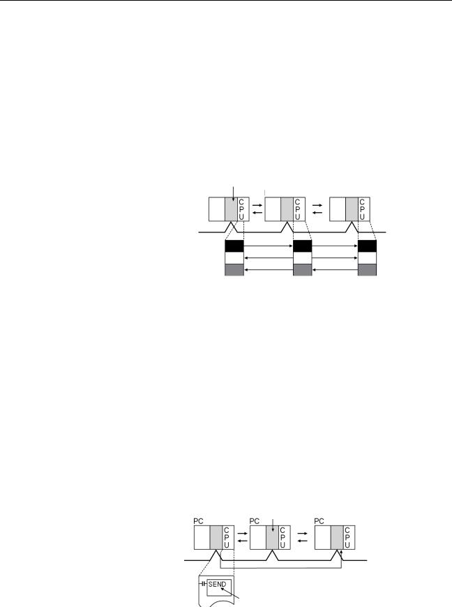
Message Service |
|
|
|
|
|
|
|
|
|
This function controls data transmission with particular nodes, reading or writ- |
|||||||
|
ing of status data, changing of operation modes, etc., by executing communi- |
|||||||
|
cations instructions on a program. The communications instructions include |
|||||||
|
SEND/RECV instructions for data transmission and CMND instructions for |
|||||||
|
issuing various commands. |
|
|
|||||
|
|
|
Controller |
Link Unit |
|
|
||
|
|
PLC |
|
PLC |
|
|
PLC |
|
Data transmission (under certain conditions) as required
Communications instruction
User program
6
Overview |
|
Section 1-1 |
SEND/RECV |
The SEND or RECV instruction sends or receives data in an area of a particu- |
|
|
lar node. |
|
|
The SEND instruction sends data from an area of the local node and writes to |
|
|
an area in the designated node. |
|
|
The RECV instruction requests the designated node to send area data and |
|
|
writes the data to the local node. |
|
CMND |
The CMND instruction issues a command to read or write data of other nodes, |
|
|
control, or read error logs. With the Controller LInk Unit, OMRON’s command |
|
|
protocol called “FINS commands” is used. |
|
Note |
Since the C200HX/HG/HE PLCs do not support the CMND instructions, arbi- |
|
|
trary commands cannot be issued. |
|
RAS |
|
|
|
RAS performs real-time monitoring of the network status. If an error occurs in |
|
|
the network, RAS records and displays the time and contents of the error. |
|
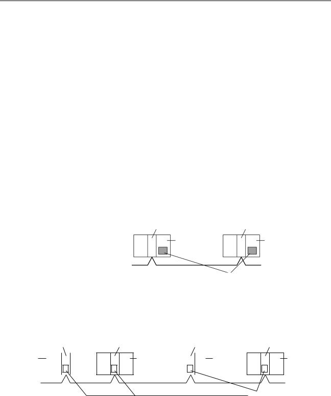
Status Area |
Data Link Status Area |
|
|
When the data link function is used, the data link status is reflected in the data |
|
|
link status area of the PLC. |
|
|
Network Status Area Other than the Data Link: |
|
|
The network status such as the state of node participation is reflected in the |
|
|
status area of the PLC. |
|
|
Controller Link Unit |
Controller Link Unit |
|
CPU Unit |
CPU Unit |
Status Area
• Data link status
• Status other than the data link
Error Log |
The error log function records contents (codes) and times of errors that occur |
||||||||||||||
|
|
|
|
|
in the network into the RAM or EEPROM, up to the maximum of 39 errors. |
||||||||||
|
|
|
|
|
The recorded errors can be read using the Controller Link Support Software |
||||||||||
|
|
|
|
|
or the message service function. |
|
|
|
|||||||
Controller Link Unit |
Controller Link Unit |
Controller Link Unit |
Controller Link Unit |
||||||||||||
CJ-series |
|
|
|
|
|
|
CS-series |
|
|
|
|
C200HX/HG/ |
|
|
CVM1, CV- |
|
|
|
|
|
|
|
|
|
|
|
|
||||
CPU Unit |
|
|
|
|
|
|
CPU Unit |
|
|
|
|
HE CPU Unit |
|
|
series CPU |
|
|
|
|
|
|
|
|
|
|
|
|
|
|
|
Unit |
|
|
|
|
|
|
|
|
|
|
|
|
|
Error log table |
||
|
|
|
|
|
|
|
|
|
|
|
|
|
|||
7

Overview |
Section 1-1 |
1-1-2 Features
The Controller Link Network has the following features to meet the various requirements of FA sites.
Data Links
Flexible and efficient data links can be created for large capacities of data as listed below.
Item |
Specifications |
|
|
Number of send words |
1,000 max. |
per node |
|
|
|
Number of send and |
C200HX/HE/HG, CVM1, CV-series, and CQM1H-series PLCs: 8,000 max. |
receive words per node |
CS/CJ-series PLCs: 12,000 max. |
|
|
|
IBM PC/AT or compatible: 32,000 max. (PCI or ISA Board) |
|
|
Data links can be automatically set, or they can be set by the user to freely change the sizes of the data areas used. A data link can also be created so that one node receives only part of the data sent from another node. This function enables users to receive only the required data, thereby increasing data link efficiency.
Message Service
The message service can send and receive up to 2,012 bytes of data (including the FINS header), allowing high volumes of data to be sent and received without having to split it up.
Twisted-pair Cable or Optical Fiber Cable Connection
The Controller Link Units can be connected to the network using either shielded twisted-pair cables or optical fiber cables. Select the system that suits your application.
Features of Twisted-pair Cable
Twisted-pair cable is easy to connect and maintain. The cable can be processed much more easily than coaxial or optical cable, thereby reducing the cost of tools and assembly time.
Connections are made to a terminal block on the Controller Link Unit and to a special connector on the Controller Link Support Board for easy system assembly and modification.
The network is equipped with the required terminating resistance built into the Units allowing the terminating resistance to be easily set at both ends of the network using a simple switch.
Features of Optical Fiber Cable
Optical Fiber Cable has superior noise resistance, so this system can provide highly reliable communications even in very noisy conditions.
The communications distance can be up to 20 km total (1 km max. between nodes) if H-PCF cable is used and up to 30 km total (2 km max. between nodes) if GI cable is used, which allows long-distance or large-scale networks.
Once the Optical Fiber Cable has been fitted with special connectors, the cables can be easily connected or disconnected.
8

Overview |
Section 1-1 |
Compatible with Different Node Configurations
The following Controller Link Units are available for communications between different models. It must be noted, however, that the wired system and optical system cannot exist in one Controller Link Network.
Wired System
•Controller Link Unit for CS/CJ-series Programmable Controllers
•Controller Link Unit for C200HX/HG/HE Programmable Controllers
•Controller Link Unit for CVM1 and CV-series Programmable Controllers
•Controller Link Unit for CQM1H-series Programmable Controllers
•Controller Link Support Board for IBM PC/ATs or compatibles (ISA or PCI bus)
Flexible Inter-network Connections
The Controller Link Network can connect to other networks (Ethernet, SYSMAC NET, SYSMAC LINK, and another Controller Link network) via CVM1, CV-series, CS-series, or CJ-series PLCs. By installing a Communications Unit for the Ethernet, SYSMAC NET or SYSMAC LINK on the same CS/CJ-series or CV-series PLC as a Controller Link Unit, a message service can be created with nodes in interconnected networks through the CVM1 or CV-series PLC. Up to three network levels are possible.
Note CS/CJ-series PLC cannot be connected directly to SYSMAC NET networks and CJ-series PLC cannot be connected directly to SYSMAC LINK networks
The programming and monitoring of other PLCs on the network can be conducted from Programming Devices connected to the PLC’s CPU Unit. Internetwork connections are possible in this case also and can cover up to three network levels.
Improved Error Handling
An error log enables quick handling of errors by recording the time the error occurred and error details. The current Controller Link Unit and Support Board status are also available, as are the data link and network status.
When an error occurs in the polling node that controls the Controller Link Network, another node automatically becomes the polling node. This prevents an error at a single node from influencing other nodes on the network, achieving a highly reliable system.
Using Repeater Units for T-Branches, Network Extensions, Network Expansions, Converting Network Sections to Optical Fiber, and Device Modularization
T-Branches enable greater wiring freedom during layout, restructuring, and expansion of networks.
Wire-to-Wire Repeater Units enable Controller Link T-Branches. T-Branches provide the following advantages:
•Cabling can conform to the layout of equipment.
•It is possible to add nodes by adding or inserting Repeater Units at branch points of an existing wired Controller Link system.
•If Repeater Units are installed at likely future branch points in the network in advance, new nodes can be added by simply connecting them to these Repeater Units.
9

Overview |
Section 1-1 |
The total length of wired networks can be extended.
At a baud rate of 2 Mbps, conventional wired networks can be up to 500 m long. By using two Repeater Units, this can be extended to a maximum of 1.5 km.
The maximum number of nodes can be extended to 62 for wired networks.
By combining version-1 Controller Link Units/Support Boards and a Repeater
Unit, it is possible to construct networks containing up to 62 nodes.
Improved noise resistance through the use of optical cabling.
By installing two Wire-to-Optical Repeater Units, optical cabling can be used for sections of the network that are the source of noise.
Devices can be modularized.
•Devices can be modularized according to Repeater Units, making wiring easier when adding, removing, or modifying devices.
•When starting up devices, components can be added to the network and debugged as they are completed.
Features and Functions of Version-1 Models
The following features and functions apply to the CS1W-CLK21-V1 and
CJ1W-CLK21-V1 Controller Link Units and the 3G8F7-CLK21-V1 Controller
Link Support Board only.
Up to 62 nodes can be connected.
Overview
When a CS1W-RPT01 Repeater Unit is used, the maximum number of nodes that can be used in the network increases to 62. (The previous limit was 32.)
Method
Use Repeater Units and turn ON bit 11 (Wired Network 62 Node Enable Bit) in the DM Parameter Area software switch D30000 + 100 × Unit No. of all nodes to enable a maximum of 62 nodes.
Restrictions
The maximum 62 nodes cannot be achieved if version-1 models and pre-ver- sion-1 models are used together in the same network.
Automatic data link creation is possible with 1:N allocations.
Overview
It is possible to perform unequal 1:N allocations of data between nodes with automatic data link creation. This makes it easy to perform data links that formerly required the user to manually edit data link parameters.
The following four automatic data link creation patterns can be used:
•Equality layout (the previous pattern)
•1:N allocation, common type
•1:N allocation, 1 to 1 type
•1:N allocation, chain type
Method
Allocation addresses and sizes are all specified using the Automatic Data Link Creation Parameters (D30000 × Unit No. + 12 to 20) in the DM Parameter Area. These values can be set using the CX-Net in the CX-Programmer version 3.2 or later.
10

Specifications and Configurations |
Section 1-2 |
Objective
This function is effective in applications that collect data from slave PLCs into a master PLC.
Restrictions
Automatic data link creation with 1:N allocations cannot be performed if ver- sion-1 models and pre-version-1 models are used together in the same network.
Change manually created data link tables during data link operation.
Overview
It is possible to modify a manually created data link table while data links are running.
Note This is possible only with manually created data link tables. Any attempt to change automatically created data link tables when data links are running will fail with an error message saying that the tables cannot be edited during data link operation will be displayed.
Method
This function can be set using the CX-Net in CX-Programmer version 3.2 or later.
Objectives
•In systems that operate non-stop and cannot be turned OFF, this function makes it possible to change the data link table to accommodate the addition of new nodes and to transfer data link tables without having to stop manually set data link communications.
•If this function is combined with the use of Repeater Units to add network nodes, it becomes possible to construct systems of greater flexibility.
Operation
When a node is being modified online, this function temporarily stops refreshing of data link data until modifications have been completed.
Nodes will participate in data links after changes to the data link table have been completed.
1-2 Specifications and Configurations
1-2-1 System Configuration
Wired Systems |
Wired systems can be used to connect CS/CJ-series PLCs, C200HX/HG/HE |
|
PLCs, CVM1 PLCs, CV-series PLCs, and IBM PC/AT or compatible comput- |
|
ers. |
CS1W-CLK21-V1 |
|
CJ1W-CLK21-V1 |
|
C200HW-CLK21 |
CVM1-CLK21 |
|
CQM1H-CLK21 |
IBM PC/AT or |
||||||||||||||||||||||||||||
Controller Link Unit |
Controller Link Unit |
Controller Link Unit |
Controller Link Unit |
Controller Link Unit |
compatible |
|||||||||||||||||||||||||||||||
CS-series |
CJ-series PLC |
C200HX/HG/HE |
|
CVM1, CV-series |
CQM1H-series |
|
|
|
||||||||||||||||||||||||||||
PLC |
PLC |
|
|
|
|
|
PLC |
|
|
|
|
|
PLC |
|
|
|
|
|
|
|
|
|
|
|
||||||||||||
|
|
|
|
|
|
|
|
|
|
|
|
|
|
|
|
|
|
|
|
|
|
|
|
|
|
|
|
|
|
|
||||||
|
|
|
|
C |
|
|
|
|
|
|
C |
|
|
|
|
|
|
C |
|
|
|
|
|
C |
|
|
|
|
C |
|
|
|
|
|
|
|
|
|
|
|
|
|
|
|
|
|
|
|
|
|
|
|
|
|
|
|
|
|
|
|
|
||||||||||||
|
|
|
|
P |
|
|
|
|
|
|
P |
|
|
|
|
|
|
P |
|
|
|
|
|
P |
|
|
|
|
P |
|
|
|
|
|
|
|
|
|
|
|
U |
|
|
|
|
|
|
U |
|
|
|
|
|
|
U |
|
|
|
|
|
U |
|
|
|
|
U |
|
|
|
|
|
|
|
|
|
|
|
|
|
|
|
|
|
|
|
|
|
|
|
|
|
|
|
|
|
|
|
|
|
|
|
|
|
|
|
|
|
|
|
|
Twisted-pair cable
3G8F7-CLK21-E-V1 Controller Link Support Board
11
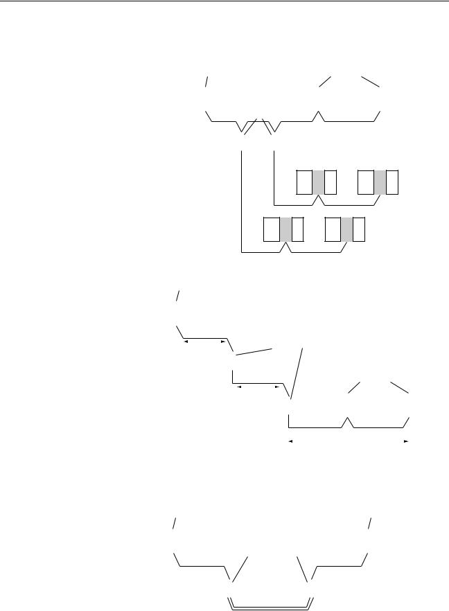
Specifications and Configurations |
|
|
|
|
|
|
Section 1-2 |
|||||||||
Connecting Repeater Units Using Twisted-pair Cable in Wired Systems |
||||||||||||||||
T-Branch Wiring |
|
|
|
|
|
|
|
|
||||||||
Wired Controller Link Unit |
|
Wired Controller Link Unit |
||||||||||||||
|
|
|
|
|
CS1W-RPT01 |
|
|
|
|
|
|
|
|
|||
|
|
|
|
|
|
|
|
|
|
|
|
|
||||
|
|
|
|
|
Repeater Units |
|
|
|
|
|
|
|
|
|||
|
|
|
|
Twisted-pair cable |
||||||||||||
|
|
|
|
|
|
|
|
|
||||||||
|
|
|
|
|
|
|
|
|
|
|
|
|
|
|
|
|
Twisted-pair cable
Long-distance Wiring
Wired Controller Link Unit
|
|
|
|
|
|
|
|
|
|
|
|
|
|
|
|
|
|
|
|
|
|
|
|
|
|
|
|
|
|
|
|
|
|
Twisted-pair cable |
CS1W-RPT01 |
|
|
|
|
|
|
|
|
|
|
|
|||||||||||
|
|
|
|
|
|
|
|
|
|
|
|
|
|
|
|
|
|
|
|
|
|
|
|
|||||
|
|
|
|
|
|
|
|
|
|
|
|
|
Repeater Units |
|
|
|
|
|
|
|
|
|
|
|
||||
|
|
|
|
|
500 m max. |
|
|
|
|
|
|
|
|
|
|
|
|
|
|
|
||||||||
|
|
|
|
|
|
|
|
|
|
|
|
|
|
|
|
|
|
|
|
|
|
|
|
|
||||
|
|
|
|
|
(See note.) |
|
|
|
|
|
|
|
|
|
|
|
|
|
|
|
|
|
|
|
|
|||
|
|
|
|
|
|
|
|
|
|
|
|
Twisted-pair |
|
|
|
|
|
|
|
|
|
|
|
|||||
|
|
|
|
|
|
|
|
|
|
|
|
cable |
|
Wired Controller Link Unit |
||||||||||||||
|
|
|
|
|
|
|
|
|
|
|
|
|
|
|
|
|
|
|
|
|
|
|
|
|
|
|
|
|
|
|
|
|
|
|
|
|
|
|
|
500 m max. |
|
|
|
|
|
|
|
|
|
|
|
|
|
|
|||
|
|
|
|
|
|
|
|
|
|
|
|
|
|
|
|
|
|
|
|
|
|
|
|
|
||||
|
|
|
|
|
|
|
|
|
|
|
(See note.) |
|
|
|
|
|
|
|
|
|
|
|
|
|
|
|||
|
|
|
|
|
|
|
|
|
|
|
|
|
|
|
|
|
|
|
|
|
|
|
|
|
|
|
|
|
|
|
|
|
|
|
|
|
|
|
|
|
|
|
|
|
|
|
|
|
|
|
|
|
|
|
|
|
|
|
|
|
|
|
|
|
|
|
|
|
|
|
|
|
|
|
|
Twisted-pair cable |
||||||||||
|
|
|
|
|
|
|
|
|
|
|
|
|
|
|
|
|
|
|
|
|
|
|
|
|||||
|
|
|
|
|
|
|
|
|
|
|
|
|
|
|
|
|
500 m max. (See note.) |
|||||||||||
|
|
|
|
|
|
|
|
|
|
|
|
|
|
|
|
|
|
|
|
|
|
|
Note: At 2 Mbit/s |
|||||
Converting Part of the Transmission Line to Optical Fiber |
||||||||||||||||||||||||||||
Wired Controller Link Unit |
|
|
|
|
|
|
|
Wired Controller Link Unit |
||||||||||||||||||||
|
|
|
|
|
|
|
|
|
|
|
|
|
CS1W-RPT02 or |
|
|
|
|
|
|
|
|
|
|
|
||||
|
|
|
|
|
|
|
|
|
|
|
|
|
|
|
|
|
|
|
|
|
|
|
|
|||||
|
|
|
|
|
|
|
|
|
|
|
|
|
CS1W-RPT03 |
|
|
|
|
|
|
|
|
|
|
|
||||
|
|
|
|
|
|
|
|
|
|
|
|
|
Repeater Units |
|
|
|
|
|
|
|
|
|
|
|
||||
|
|
Twisted-pair cable |
Twisted-pair cable |
|||||||||||||||||||||||||
|
|
|
|
|
|
|
||||||||||||||||||||||
|
|
|
|
|
|
|
|
|
|
|
|
|
|
|
|
|
|
|
|
|
|
|
|
|
|
|
|
|
|
|
|
|
|
|
|
|
|
|
|
|
|
|
|
|
|
|
|
|
|
|
|
|
|
|
|
|
|
Optical cable (H-PCF or GI)
Two Repeater Units of the same model must be used when part of the transmission line uses optical fiber.
12
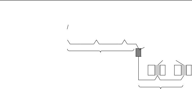
Specifications and Configurations |
Section 1-2 |
Maximum Configuration of 62 Nodes
Wired Controller Link Unit
|
|
|
|
|
|
|
|
|
|
|
CS1W-RPT01 |
|
|
|
Twisted-pair cable |
|
|
|
|||||
|
|
|
|
|
|
Repeater Unit |
|||||
32 nodes max.
Wired Controller Link Unit
Twisted-pair cable
32 nodes max.
The following Controller Link Units/Support Boards must be used to construct a network with more than 32 nodes:
CS1W-CLK21-V1 CJ1W-CLK21-V1 3G8F7-CLK21-E-V1
Note 1. The network will not operate correctly unless all nodes within the network use the above Units/Boards.
2.Only node addresses 1 through 32 can be used on networks for which 62 nodes have not been enabled.
1-2-2 General Specifications
General specifications are the same for the C200HX/HG/HE, CS-series, CJseries, CVM1, CV-series, and CQM1H-series PLCs.
13
 Loading...