


CPM2A
Table of contents
 Loading...
OPERATION MANUAL
Programmable Controllers
SYSMAC
CPM2A
Cat. No. W352-E1-07

CPM2A Programmable Controllers
Operation Manual
Revised November 2005

iv

Notice:
OMRON products are manufactured for use according to proper procedures by a qualified operator
and only for the purposes described in this manual.
The following conventions are used to indicate and classify precautions in this manual. Always heed
the information provided with them. Failure to heed precautions can result in injury to people or damage to property.
DANGER Indicates an imminently hazardous situation which, if not avoided, will result in death or
!
serious injury. Additionally, there may be severe property damage.
WARNING Indicates a potentially hazardous situation which, if not avoided, could result in death or
!
serious injury. Additionally, there may be severe property damage.
Caution Indicates a potentially hazardous situation which, if not avoided, may result in minor or
!
moderate injury, or property damage.
OMRON Product References
All OMRON products are capitalized in this manual. The word “Unit” is also capitalized when it refers
to an OMRON product, regardless of whether or not it appears in the proper name of the product.
The abbreviation “Ch,” which appears in some displays and on some OMRON products, often means
“word” and is abbreviated “Wd” in documentation in this sense.
The abbreviation “PC” means Programmable Controller and is not used as an abbreviation for anything else.
Visual Aids
The following headings appear in the left column of the manual to help you locate different types of
information.
OMRON, 1999
All rights reserved. No part of this publication may be reproduced, stored in a retrieval system, or transmitted, in any
form, or by any means, mechanical, electronic, photocopying, recording, or otherwise, without the prior written permission of OMRON.
No patent liability is assumed with respect to the use of the information contained herein. Moreover, because OMRON is
constantly striving to improve its high-quality products, the information contained in this manual is subject to change
without notice. Every precaution has been taken in the preparation of this manual. Nevertheless, OMRON assumes no
responsibility for errors or omissions. Neither is any liability assumed for damages resulting from the use of the information contained in this publication.
Note Indicates information of particular interest for efficient and convenient operation
of the product.
1, 2, 3... 1. Indicates lists of one sort or another, such as procedures, checklists, etc.
v

vi

TABLE OF CONTENTS
PRECAUTIONS xv. . . . . . . . . . . . . . . . . . . . . . . . . . . . . . . . .
1 Intended Audience xvi. . . . . . . . . . . . . . . . . . . . . . . . . . . . . . . . . . . . . . . . . . . . . . . . . . . . . . . . . . .
2 General Precautions xvi. . . . . . . . . . . . . . . . . . . . . . . . . . . . . . . . . . . . . . . . . . . . . . . . . . . . . . . . . .
3 Safety Precautions xvi. . . . . . . . . . . . . . . . . . . . . . . . . . . . . . . . . . . . . . . . . . . . . . . . . . . . . . . . . . .
4 Operating Environment Precautions xvii. . . . . . . . . . . . . . . . . . . . . . . . . . . . . . . . . . . . . . . . . . . . .
5 Application Precautions xviii. . . . . . . . . . . . . . . . . . . . . . . . . . . . . . . . . . . . . . . . . . . . . . . . . . . . . .
6 EC Directives xx. . . . . . . . . . . . . . . . . . . . . . . . . . . . . . . . . . . . . . . . . . . . . . . . . . . . . . . . . . . . . .
7 CPM2A 24-VDC CPU Unit Conformance to NK Standards xxiii. . . . . . . . . . . . . . . . . . . . . . . . . .
SECTION 1
Introduction 1. . . . . . . . . . . . . . . . . . . . . . . . . . . . . . . . . . . .
1-1 CPM2A Features and Functions 2. . . . . . . . . . . . . . . . . . . . . . . . . . . . . . . . . . . . . . . . . . . .
1-2 Basic System Configurations 9. . . . . . . . . . . . . . . . . . . . . . . . . . . . . . . . . . . . . . . . . . . . . . .
1-3 Structure and Operation 12. . . . . . . . . . . . . . . . . . . . . . . . . . . . . . . . . . . . . . . . . . . . . . . . . . .
1-4 Functions Listed by Usage 18. . . . . . . . . . . . . . . . . . . . . . . . . . . . . . . . . . . . . . . . . . . . . . . . .
1-5 Comparison with the CPM1A 21. . . . . . . . . . . . . . . . . . . . . . . . . . . . . . . . . . . . . . . . . . . . . .
1-6 Preparation for Operation 26. . . . . . . . . . . . . . . . . . . . . . . . . . . . . . . . . . . . . . . . . . . . . . . . . .
SECTION 2
Unit Specifications and Components 29. . . . . . . . . . . . . . . .
2-1 Specifications 30. . . . . . . . . . . . . . . . . . . . . . . . . . . . . . . . . . . . . . . . . . . . . . . . . . . . . . . . . . .
2-2 Unit Components 37. . . . . . . . . . . . . . . . . . . . . . . . . . . . . . . . . . . . . . . . . . . . . . . . . . . . . . . .
SECTION 3
Installation and Wiring 47. . . . . . . . . . . . . . . . . . . . . . . . . . .
3-1 Design Precautions 48. . . . . . . . . . . . . . . . . . . . . . . . . . . . . . . . . . . . . . . . . . . . . . . . . . . . . . .
3-2 Selecting an Installation Site 48. . . . . . . . . . . . . . . . . . . . . . . . . . . . . . . . . . . . . . . . . . . . . . .
3-3 Installing the CPM2A 50. . . . . . . . . . . . . . . . . . . . . . . . . . . . . . . . . . . . . . . . . . . . . . . . . . . . .
3-4 Wiring and Connections 53. . . . . . . . . . . . . . . . . . . . . . . . . . . . . . . . . . . . . . . . . . . . . . . . . . .
SECTION 4
Using a Programming Console 89. . . . . . . . . . . . . . . . . . . . .
4-1 Compatible Programming Consoles 90. . . . . . . . . . . . . . . . . . . . . . . . . . . . . . . . . . . . . . . . .
4-2 Programming Console Operations 96. . . . . . . . . . . . . . . . . . . . . . . . . . . . . . . . . . . . . . . . . . .
4-3 Programming Example 120. . . . . . . . . . . . . . . . . . . . . . . . . . . . . . . . . . . . . . . . . . . . . . . . . . . .
SECTION 5
Test Runs and Error Processing 127. . . . . . . . . . . . . . . . . . . .
5-1 Initial System Checks and Test Run Procedure 128. . . . . . . . . . . . . . . . . . . . . . . . . . . . . . . . .
5-2 Self-diagnostic Functions 129. . . . . . . . . . . . . . . . . . . . . . . . . . . . . . . . . . . . . . . . . . . . . . . . . .
5-3 Programming Console Operation Errors 132. . . . . . . . . . . . . . . . . . . . . . . . . . . . . . . . . . . . . .
5-4 Programming Errors 132. . . . . . . . . . . . . . . . . . . . . . . . . . . . . . . . . . . . . . . . . . . . . . . . . . . . . .
5-5 Troubleshooting Flowcharts 133. . . . . . . . . . . . . . . . . . . . . . . . . . . . . . . . . . . . . . . . . . . . . . . .
5-6 Maintenance Inspections 141. . . . . . . . . . . . . . . . . . . . . . . . . . . . . . . . . . . . . . . . . . . . . . . . . .
5-7 Battery Replacement 142. . . . . . . . . . . . . . . . . . . . . . . . . . . . . . . . . . . . . . . . . . . . . . . . . . . . .
SECTION 6
Expansion Memory Unit 145. . . . . . . . . . . . . . . . . . . . . . . . . .
6-1 Overview 146. . . . . . . . . . . . . . . . . . . . . . . . . . . . . . . . . . . . . . . . . . . . . . . . . . . . . . . . . . . . . .
6-2 Specifications and Nomenclature 147. . . . . . . . . . . . . . . . . . . . . . . . . . . . . . . . . . . . . . . . . . .
6-3 Handling 148. . . . . . . . . . . . . . . . . . . . . . . . . . . . . . . . . . . . . . . . . . . . . . . . . . . . . . . . . . . . . . .
vii

TABLE OF CONTENTS
Appendices
A Standard Models 155. . . . . . . . . . . . . . . . . . . . . . . . . . . . . . . . . . . . . . . . . . . . . . . . . . . . . . . . . . .
B Dimensions 159. . . . . . . . . . . . . . . . . . . . . . . . . . . . . . . . . . . . . . . . . . . . . . . . . . . . . . . . . . . . . . . .
Index 167. . . . . . . . . . . . . . . . . . . . . . . . . . . . . . . . . . . . . . . . . .
Revision History 171. . . . . . . . . . . . . . . . . . . . . . . . . . . . . . . . .
viii

About this Manual:
The CPM2A is a compact, high-speed Programmable Controller (PC) designed for control operations in
systems requiring from 10 to 120 I/O points per PC. There are two manuals describing the setup and
operation of the CPM2A: The CPM2A Operation Manual (this manual) and the CPM1/CPM1A/CPM2A/
CPM2C/SRM1(-V2) Programming Manual (W353). (The CPM1/CPM1A/CPM2A/CPM2C/SRM1(-V2)
Programming Manual is referred to as simply the Programming Manual in this manual.)
This manual describes the system configuration and installation of the CPM2A and provides a basic
explanation of operating procedures for the Programming Consoles. It also introduces the capabilities of
CX-Programmer, the SYSMAC Support Software (SSS) and SYSMAC-CPT Support Software. Read this
manual first to acquaint yourself with the CPM2A.
The Programming Manual (W353) provides detailed descriptions of the CPM2A’s programming functions
and application methods for Expansion Units. The SYSMAC Support Software Operation Manuals:
Basics and C-series PCs (W247 and W248) provide descriptions of SSS operations for the CPM2A and
other SYSMAC C-series PCs. The WS02-CXPjj-E CX-Programmer Operation Manual (W414) provides details of operations for the WS02-CXPjj-E CX-Programmer. The SYSMAC-CPT Support Soft-
ware Quick Start Guide (W332) and User Manual (W333) provide descriptions of ladder diagram operations in the Windows environment.
Please read this manual carefully and be sure you understand the information provided before attempting
to install and operate the CPM2A.
Section 1 gives a brief overview of the steps involved in developing of a CPM2A System, describes the
possible system configurations, and describes the CPM2A’s special features and functions.
Section 2 provides the technical specifications of the Units that go together to create a CPM2A PC and
describes the main components of the Units.
Section 3 describes how to install and wire a CPM2A PC.
Section 4 describes how to connect the Programming Console, and how to perform the various program-
ming operations.
Section 5 describes how to perform a test run and how to diagnose and correct the hardware and software errors that can occur during PC operation.
Section 6 describes how to use the CPM1-EMU01-V1 Expansion Memory Unit. Follow the handling precautions and procedures to properly use the Unit.
Appendix A provides tables of CPM2A Units and related products.
Appendix B provides the dimensions of CPM2A Units.
!
WARNING Failure to read and understand the information provided in this manual may result in
personal injury or death, damage to the product, or product failure. Please read each
section in its entirety and be sure you understand the information provided in the section
and related sections before attempting any of the procedures or operations given.
ix

Read and Understand this Manual
Á
Á
Á
Á
Á
Á
Á
Á
Á
Á
Á
Á
Á
Á
Á
Please read and understand this manual before using the product. Please consult your OMRON
representative if you have any questions or comments.
Warranty and Limitations of Liability
WARRANTY
OMRON’s exclusive warranty is that the products are free from defects in materials and workmanship for
БББББББББББББББББББББББББББББББ
a period of one year (or other period if specified) from date of sale by OMRON.
БББББББББББББББББББББББББББББББ
OMRON MAKES NO WARRANTY OR REPRESENTATION, EXPRESS OR IMPLIED, REGARDING
БББББББББББББББББББББББББББББББ
NON–INFRINGEMENT, MERCHANTABILITY, OR FITNESS FOR PARTICULAR PURPOSE OF THE
БББББББББББББББББББББББББББББББ
PRODUCTS. ANY BUYER OR USER ACKNOWLEDGES THAT THE BUYER OR USER ALONE HAS
БББББББББББББББББББББББББББББББ
DETERMINED THAT THE PRODUCTS WILL SUITABLY MEET THE REQUIREMENTS OF THEIR
INTENDED USE. OMRON DISCLAIMS ALL OTHER WARRANTIES, EXPRESS OR IMPLIED.
БББББББББББББББББББББББББББББББ
БББББББББББББББББББББББББББББББ
LIMITATIONS OF LIABILITY
OMRON SHALL NOT BE RESPONSIBLE FOR SPECIAL, INDIRECT, OR CONSEQUENTIAL
DAMAGES, LOSS OF PROFITS OR COMMERCIAL LOSS IN ANY WAY CONNECTED WITH THE
БББББББББББББББББББББББББББББББ
PRODUCTS, WHETHER SUCH CLAIM IS BASED ON CONTRACT, WARRANTY, NEGLIGENCE, OR
БББББББББББББББББББББББББББББББ
STRICT LIABILITY.
БББББББББББББББББББББББББББББББ
In no event shall the responsibility of OMRON for any act exceed the individual price of the product on
БББББББББББББББББББББББББББББББ
which liability is asserted.
БББББББББББББББББББББББББББББББ
IN NO EVENT SHALL OMRON BE RESPONSIBLE FOR WARRANTY, REPAIR, OR OTHER CLAIMS
БББББББББББББББББББББББББББББББ
REGARDING THE PRODUCTS UNLESS OMRON’S ANALYSIS CONFIRMS THAT THE PRODUCTS
БББББББББББББББББББББББББББББББ
WERE PROPERLY HANDLED, STORED, INSTALLED, AND MAINTAINED AND NOT SUBJECT TO
БББББББББББББББББББББББББББББББ
CONTAMINATION, ABUSE, MISUSE, OR INAPPROPRIATE MODIFICATION OR REPAIR.
xi

Application Considerations
Á
Á
Á
Á
Á
Á
Á
Á
Á
Á
Á
Á
Á
Á
Á
Á
Á
Á
Á
Á
Á
Á
SUITABILITY FOR USE
OMRON shall not be responsible for conformity with any standards, codes, or regulations that apply to
БББББББББББББББББББББББББББББББ
the combination of products in the customer’s application or use of the products.
БББББББББББББББББББББББББББББББ
At the customer’s request, OMRON will provide applicable third party certification documents identifying
БББББББББББББББББББББББББББББББ
ratings and limitations of use that apply to the products. This information by itself is not sufficient for a
БББББББББББББББББББББББББББББББ
complete determination of the suitability of the products in combination with the end product, machine,
БББББББББББББББББББББББББББББББ
system, or other application or use.
БББББББББББББББББББББББББББББББ
The following are some examples of applications for which particular attention must be given. This is not
БББББББББББББББББББББББББББББББ
intended to be an exhaustive list of all possible uses of the products, nor is it intended to imply that the
БББББББББББББББББББББББББББББББ
uses listed may be suitable for the products:
БББББББББББББББББББББББББББББББ
• Outdoor use, uses involving potential chemical contamination or electrical interference, or conditions
БББББББББББББББББББББББББББББББ
or uses not described in this manual.
БББББББББББББББББББББББББББББББ
• Nuclear energy control systems, combustion systems, railroad systems, aviation systems, medical
БББББББББББББББББББББББББББББББ
equipment, amusement machines, vehicles, safety equipment, and installations subject to separate
БББББББББББББББББББББББББББББББ
industry or government regulations.
БББББББББББББББББББББББББББББББ
• Systems, machines, and equipment that could present a risk to life or property.
БББББББББББББББББББББББББББББББ
Please know and observe all prohibitions of use applicable to the products.
БББББББББББББББББББББББББББББББ
БББББББББББББББББББББББББББББББ
NEVER USE THE PRODUCTS FOR AN APPLICATION INVOLVING SERIOUS RISK TO LIFE OR
БББББББББББББББББББББББББББББББ
PROPERTY WITHOUT ENSURING THAT THE SYSTEM AS A WHOLE HAS BEEN DESIGNED TO
ADDRESS THE RISKS, AND THAT THE OMRON PRODUCTS ARE PROPERLY RATED AND
БББББББББББББББББББББББББББББББ
INSTALLED FOR THE INTENDED USE WITHIN THE OVERALL EQUIPMENT OR SYSTEM.
БББББББББББББББББББББББББББББББ
БББББББББББББББББББББББББББББББ
PROGRAMMABLE PRODUCTS
OMRON shall not be responsible for the user’s programming of a programmable product, or any
БББББББББББББББББББББББББББББББ
consequence thereof.
xii

Disclaimers
Á
Á
Á
Á
Á
Á
Á
Á
Á
Á
Á
Á
Á
CHANGE IN SPECIFICATIONS
БББББББББББББББББББББББББББББББ
Product specifications and accessories may be changed at any time based on improvements and other
reasons.
БББББББББББББББББББББББББББББББ
БББББББББББББББББББББББББББББББ
It is our practice to change model numbers when published ratings or features are changed, or when
significant construction changes are made. However, some specifications of the products may be
БББББББББББББББББББББББББББББББ
changed without any notice. When in doubt, special model numbers may be assigned to fix or establish
БББББББББББББББББББББББББББББББ
key specifications for your application on your request. Please consult with your OMRON representative
БББББББББББББББББББББББББББББББ
at any time to confirm actual specifications of purchased products.
БББББББББББББББББББББББББББББББ
DIMENSIONS AND WEIGHTS
Dimensions and weights are nominal and are not to be used for manufacturing purposes, even when
tolerances are shown.
БББББББББББББББББББББББББББББББ
PERFORMANCE DATA
Performance data given in this manual is provided as a guide for the user in determining suitability and
БББББББББББББББББББББББББББББББ
does not constitute a warranty. It may represent the result of OMRON’s test conditions, and the users
БББББББББББББББББББББББББББББББ
must correlate it to actual application requirements. Actual performance is subject to the OMRON
БББББББББББББББББББББББББББББББ
Warranty and Limitations of Liability.
БББББББББББББББББББББББББББББББ
The information in this manual has been carefully checked and is believed to be accurate; however, no
responsibility is assumed for clerical, typographical, or proofreading errors, or omissions.
БББББББББББББББББББББББББББББББ
ERRORS AND OMISSIONS
xiii

xiv

PRECAUTIONS
This section provides general precautions for using the Programmable Controller (PC) and related devices.
The information contained in this section is important for the safe and reliable application of the Programmable Controller. You must read this section and understand the information contained before attempting to set up or operate a
PC system.
1 Intended Audience xvi. . . . . . . . . . . . . . . . . . . . . . . . . . . . . . . . . . . . . . . . . . . . . . . . . . . . . . . . . . . .
2 General Precautions xvi. . . . . . . . . . . . . . . . . . . . . . . . . . . . . . . . . . . . . . . . . . . . . . . . . . . . . . . . . . .
3 Safety Precautions xvi. . . . . . . . . . . . . . . . . . . . . . . . . . . . . . . . . . . . . . . . . . . . . . . . . . . . . . . . . . . .
4 Operating Environment Precautions xvii. . . . . . . . . . . . . . . . . . . . . . . . . . . . . . . . . . . . . . . . . . . . . .
5 Application Precautions xviii. . . . . . . . . . . . . . . . . . . . . . . . . . . . . . . . . . . . . . . . . . . . . . . . . . . . . . . .
6 EC Directives xx. . . . . . . . . . . . . . . . . . . . . . . . . . . . . . . . . . . . . . . . . . . . . . . . . . . . . . . . . . . . . . . .
7 CPM2A 24-VDC CPU Unit Conformance to NK Standards xxiii. . . . . . . . . . . . . . . . . . . . . . . . . . .
xv

1 Intended Audience
This manual is intended for the following personnel, who must also have knowledge of electrical systems (an electrical engineer or the equivalent).
• Personnel in charge of installing FA systems.
• Personnel in charge of designing FA systems.
• Personnel in charge of managing FA systems and facilities.
2 General Precautions
The user must operate the product according to the performance specifications
described in the operation manuals.
Before using the product under conditions which are not described in the manual
or applying the product to nuclear control systems, railroad systems, aviation
systems, vehicles, combustion systems, medical equipment, amusement machines, safety equipment, and other systems, machines, and equipment that
may have a serious influence on lives and property if used improperly, consult
your OMRON representative.
Make sure that the ratings and performance characteristics of the product are
sufficient for the systems, machines, and equipment, and be sure to provide the
systems, machines, and equipment with double safety mechanisms.
This manual provides information for programming and operating the Unit. Be
sure to read this manual before attempting to use the Unit and keep this manual
close at hand for reference during operation.
5Safety Precautions
WARNING It is extremely important that a PC and all PC Units be used for the specified
!
purpose and under the specified conditions, especially in applications that can
directly or indirectly affect human life. You must consult with your OMRON
representative before applying a PC System to the above-mentioned
applications.
3 Safety Precautions
WARNING Do not attempt to take any Unit apart while the power is being supplied. Doing so
!
may result in electric shock.
WARNING Do not touch any of the terminals or terminal blocks while the power is being
!
supplied. Doing so may result in electric shock.
WARNING Do not attempt to disassemble, repair, or modify any Units. Any attempt to do so
!
may result in malfunction, fire, or electric shock.
WARNING Provide safety measures in external circuits (i.e., not in the Programmable
!
Controller), including the following items, in order to ensure safety in the system
if an abnormality occurs due to malfunction of the PC or another external factor
affecting the PC operation. Not doing so may result in serious accidents.
xvi
• Emergency stop circuits, interlock circuits, limit circuits, and similar safety
measures must be provided in external control circuits.
• The PC will turn OFF all outputs when its self-diagnosis function detects any
error or when a severe failure alarm (FALS) instruction is executed. As a countermeasure for such errors, external safety measures must be provided to ensure safety in the system.

Operating Environment Precautions
• The PC outputs may remain ON or OFF due to deposition or burning of the
output relays or destruction of the output transistors. As a countermeasure for
such problems, external safety measures must be provided to ensure safety in
the system.
• When the 24-VDC output (service power supply to the PC) is overloaded or
short-circuited, the voltage may drop and result in the outputs being turned
OFF. As a countermeasure for such problems, external safety measures must
be provided to ensure safety in the system.
WARNING When transferring programs to other nodes, or when making changes to I/O
!
memory, confirm the safety of the destination node before transfer. Not doing so
may result in injury.
Caution Execute online edit only after confirming that no adverse effects will be caused
!
by extending the cycle time. Otherwise, the input signals may not be readable.
Caution Tighten the screws on the terminal block of the AC Power Supply Unit to the
!
torque specified in the operation manual. The loose screws may result in burning
or malfunction.
4
Caution When connecting the PC to a personal computer or other peripheral device, ei-
!
ther ground the 0-V side of the PC or do not ground the PC at all. Although some
grounding methods short the 24-V side, as shown in the following diagram, never do so with the PC.
INCORRECT Grounding: Shorting the 24-V side of the Power Supply
Non-isolated DC
0 V
power supply
0 V 0 V
PC
24 V
4 Operating Environment Precautions
Caution Do not operate the control system in the following places:
!
• Locations subject to direct sunlight.
• Locations subject to temperatures or humidity outside the range specified in
the specifications.
• Locations subject to condensation as the result of severe changes in tempera-
ture.
• Locations subject to corrosive or flammable gases.
• Locations subject to dust (especially iron dust) or salts.
• Locations subject to exposure to water, oil, or chemicals.
• Locations subject to shock or vibration.
Peripheral device
Caution Take appropriate and sufficient countermeasures when installing systems in the
!
following locations:
xvii

• Locations subject to static electricity or other forms of noise.
• Locations subject to strong electromagnetic fields.
• Locations subject to possible exposure to radioactivity.
• Locations close to power supplies.
Caution The operating environment of the PC System can have a large effect on the lon-
!
gevity and reliability of the system. Improper operating environments can lead to
malfunction, failure, and other unforeseeable problems with the PC System. Be
sure that the operating environment is within the specified conditions at installation and remains within the specified conditions during the life of the system.
5 Application Precautions
Observe the following precautions when using the PC System.
WARNING Always heed these precautions. Failure to abide by the following precautions
!
could lead to serious or possibly fatal injury.
• Always connect to a ground such that the grounding resistance does not exceed 100 Ω when installing the Units. Not connecting to the correct ground
may result in electric shock.
• Always turn OFF the power supply to the PC before attempting any of the following. Not turning OFF the power supply may result in malfunction or electric
shock.
• Mounting or dismounting I/O Units, CPU Units, or any other Units.
• Assembling the Units.
• Setting DIP switches or rotary switches.
• Connecting or wiring the cables.
• Connecting or disconnecting the connectors.
5Application Precautions
Caution Failure to abide by the following precautions could lead to faulty operation of the
!
PC or the system, or could damage the PC or PC Units. Always heed these precautions.
• Fail-safe measures must be taken by the customer to ensure safety in the
event of incorrect, missing, or abnormal signals caused by broken signal lines,
momentary power interruptions, or other causes.
• Construct a control circuit so that power supply for the I/O circuits does not
come ON before power supply for the Unit. If power supply for the I/O circuits
comes ON before power supply for the Unit, normal operation may be temporarily interrupted.
• If the operating mode is changed from RUN or MONITOR mode to PROGRAM
mode, with the IOM Hold Bit ON, the output will hold the most recent status. In
such a case, ensure that the external load does not exceed specifications. (If
operation is stopped because of an operation error (including FALS instructions), the values in the internal memory of the CPU Unit will be saved, but the
outputs will all turn OFF.)
• Always use the power supply voltage specified in the operation manuals. An
incorrect voltage may result in malfunction or burning.
• Take appropriate measures to ensure that the specified power with the rated
voltage and frequency is supplied. Be particularly careful in places where the
power supply is unstable. An incorrect power supply may result in malfunction.
• Install external breakers and take other safety measures against short-circuiting in external wiring. Insufficient safety measures against short-circuiting may
result in burning.
xviii

Application Precautions
5
• Do not apply voltages to the input terminals in excess of the rated input voltage.
Excess voltages may result in burning.
• Do not apply voltages or connect loads to the output terminals in excess of the
maximum switching capacity. Excess voltage or loads may result in burning.
• Disconnect the functional ground terminal when performing withstand voltage
tests. Not disconnecting the functional ground terminal may result in burning.
• Install the Unit properly as specified in the operation manual. Improper installation of the Unit may result in malfunction.
• Be sure that all the mounting screws, terminal screws, and cable connector
screws are tightened to the torque specified in the relevant manuals. Incorrect
tightening torque may result in malfunction.
• Be sure to leave the labels attached at the time of shipment on the CPM1 or
CPM2A when wiring in order to prevent wiring cuttings from entering the Unit.
• Remove the label after the completion of wiring to ensure proper heat dissipation. Leaving the label attached may result in malfunction.
• Be sure to perform wiring in accordance with the relevant operation manual.
Incorrect wiring may result in burning.
• Use crimp terminals for wiring. Do not connect bare stranded wires directly to
terminals. Connection of bare stranded wires may result in burning.
• Double-check all the wiring before turning ON the power supply. Incorrect wiring may result in burning.
• Be sure that the terminal blocks, expansion cables, and other items with locking devices are properly locked into place. Improper locking may result in malfunction.
• Be sure that terminal blocks and connectors are connected in the specified direction with the correct polarity. Not doing so may result in malfunction.
• Check the user program for proper execution before actually running it on the
Unit. Not checking the program may result in an unexpected operation.
• Confirm that no adverse effect will occur in the system before attempting any of
the following. Not doing so may result in an unexpected operation.
• Changing the operating mode of the PC.
• Force-setting/force-resetting any bit in memory.
• Changing the present value of any word or any set value in memory.
• Resume operation only after transferring to the new CPU Unit the contents of
the DM and HR Areas required for resuming operation. Not doing so may result
in an unexpected operation.
• Do not pull on the cables or bend the cables beyond their natural limit. Doing
either of these may break the cables.
• Do not place objects on top of the cables. Doing so may break the cables.
• Do not short the battery terminals or charge, disassemble, heat, or incinerate
the battery. Do not subject the battery to strong shocks. Doing any of these
may result in leakage, rupture, heat generation, or ignition of the battery. Dispose of any battery that has been dropped on the floor or otherwise subjected
to excessive shock. Batteries that have been subjected to shock may leak if
they are used.
• When replacing parts, be sure to confirm that the rating of a new part is correct.
Not doing so may result in malfunction or burning.
• Before touching the Unit, be sure to first touch a grounded metallic object in
order to discharge any static build-up. Not doing so may result in malfunction or
damage.
• Do not touch the expansion I/O connecting cable while the power is being supplied in order to prevent any malfunction due to static electricity.
xix

• When using a thermocouple-input type Temperature Sensor Unit, observe the
following precautions:
• Do not remove the cold junction compensator attached at the time of deliv-
ery. If the cold junction compensator is removed the Unit will not be able to
measure temperatures correctly.
• Each of the input circuits is calibrated with the cold junction compensator
attached to the Unit. If the Unit is used with the cold junction compensator
from other Units, the Unit will not be able to measure temperatures correctly.
• Do not touch the cold junction compensator. Doing so may result in incor-
rect temperature measurement.
6 EC Directives
6-1 Applicable Directives
• EMC Directives
• Low Voltage Directive
6-2 Concepts
EMC Directives
OMRON devices that comply with EC Directives also conform to the related
EMC standards so that they can be more easily built into other devices or the
overall machine. The actual products have been checked for conformity to EMC
standards (see the following note). Whether the products conform to the standards in the system used by the customer, however, must be checked by the
customer.
EMC-related performance of the OMRON devices that comply with EC Directives will vary depending on the configuration, wiring, and other conditions of the
equipment or control panel on which the OMRON devices are installed. The customer must, therefore, perform the final check to confirm that devices and the
overall machine conform to EMC standards.
6EC Directives
Note Applicable EMC (Electromagnetic Compatibility) standards are as follows:
EMS (Electromagnetic Susceptibility): EN61131-2
EMI (Electromagnetic Interference): EN61000-6-4
Low Voltage Directive
Always ensure that devices operating at voltages of 50 to 1,000 VAC and 75 to
1,500 VDC meet the required safety standards for the PC (EN61131-2).
6-3 Conformance to EC Directives
The CPM2A PCs comply with EC Directives. To ensure that the machine or device in which the CPM2A PC is used complies with EC directives, the PC must be
installed as follows:
1, 2, 3... 1. The CPM2A PC must be installed within a control panel.
2. Reinforced insulation or double insulation must be used for the DC power
supplies used for the communications and I/O power supplies.
3. CPM2A PCs complying with EC Directives also conform to the Common
Emission Standard (EN61000-6-4). Radiated emission characteristics
(10-m regulations) may vary depending on the configuration of the control
panel used, other devices connected to the control panel, wiring, and other
conditions. You must therefore confirm that the overall machine or equipment complies with EC Directives.
(Radiated emission: 10-m regulations)
xx

EC Directives
6-4 Relay Output Noise Reduction Methods
The CPM2A PCs conform to the Common Emission Standards (EN61000-6-4)
of the EMC Directives. However, the noise generated when the PC is switched
ON or OFF using the relay output may not satisfy these standards. In such a
case, a noise filter must be connected to the load side or other appropriate countermeasures must be provided external to the PC.
Countermeasures taken to satisfy the standards vary depending on the devices
on the load side, wiring, configuration of machines, etc. Following are examples
of countermeasures for reducing the generated noise.
Countermeasures
(Refer to EN61000-6-4 for more details.)
Countermeasures are not required if the frequency of load switching for the
whole system with the PC included is less than 5 times per minute.
Countermeasures are required if the frequency of load switching for the whole
system with the PC included is 5 times or more per minute.
6
xxi
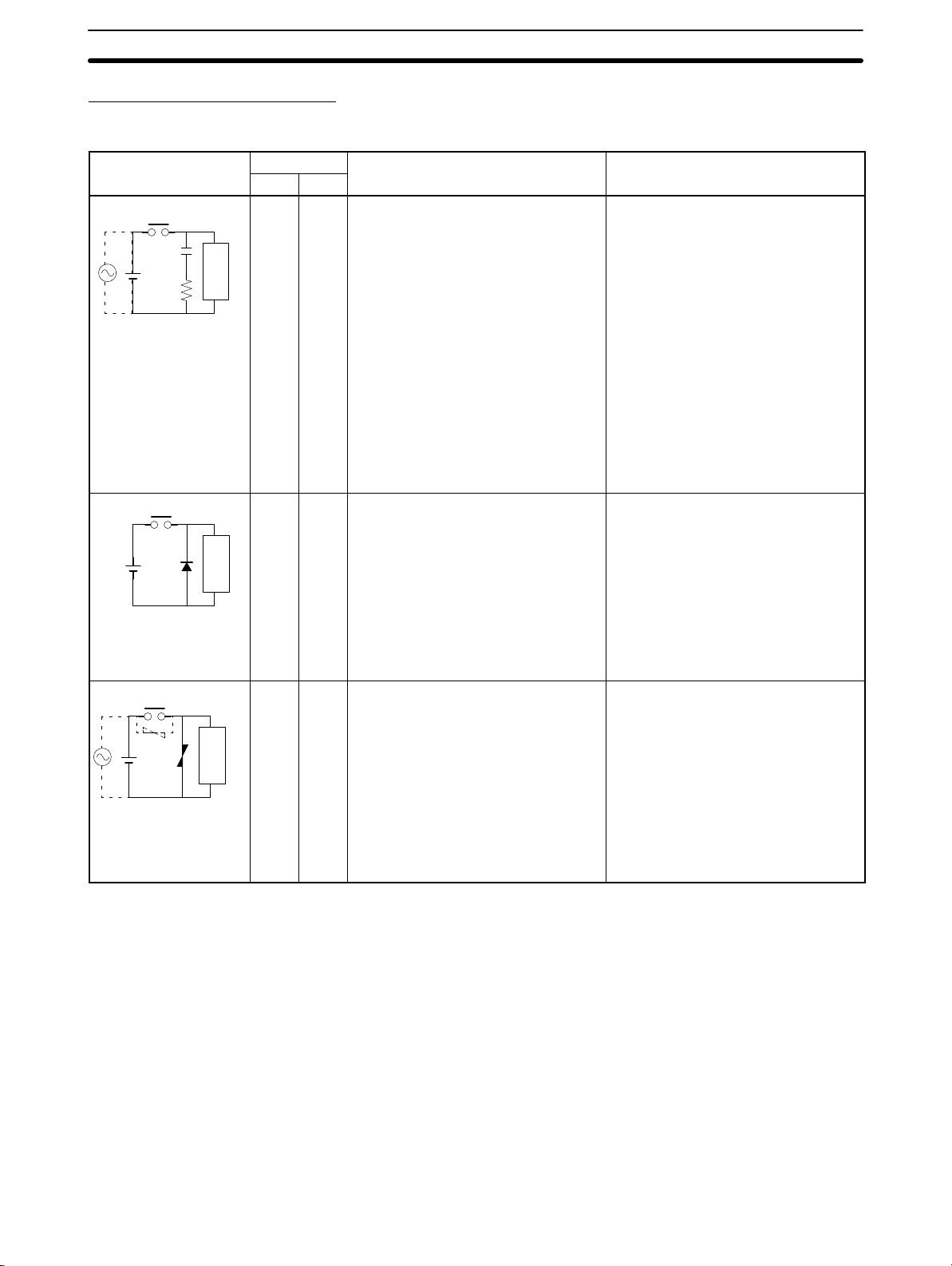
Countermeasure Examples
When switching an inductive load, connect a surge protector, diodes, etc., in parallel with the load or contact as shown below.
Circuit Current Characteristic Required element
AC DC
CR method
Power
supply
Diode method
Power
supply
Varistor method
Power
supply
Yes Yes If the load is a relay or solenoid, there
Inductive
load
No Yes The diode connected in parallel with
Inductive
load
Yes Yes The varistor method prevents the
Inductive
load
is a time lag between the moment the
circuit is opened and the moment the
load is reset.
If the supply voltage is 24 to 48 V,
insert the surge protector in parallel
with the load. If the supply voltage is
100 to 200 V, insert the surge
protector between the contacts.
the load changes energy accumulated
by the coil into a current, which then
flows into the coil so that the current
will be converted into Joule heat by
the resistance of the inductive load.
This time lag, between the moment
the circuit is opened and the moment
the load is reset, caused by this
method is longer than that caused by
the CR method.
imposition of high voltage between the
contacts by using the constant voltage
characteristic of the varistor. There is
time lag between the moment the
circuit is opened and the moment the
load is reset.
If the supply voltage is 24 to 48 V,
insert the varistor in parallel with the
load. If the supply voltage is 100 to
200 V, insert the varistor between the
contacts.
6EC Directives
The capacitance of the capacitor must
be 1 to 0.5 µF per contact current of
1 A and resistance of the resistor must
be 0.5 to 1 Ω per contact voltage of
1 V. These values, however, vary with
the load and the characteristics of the
relay. Decide these values from
experiments, and take into
consideration that the capacitance
suppresses spark discharge when the
contacts are separated and the
resistance limits the current that flows
into the load when the circuit is closed
again.
The dielectric strength of the capacitor
must be 200 to 300 V. If the circuit is
an AC circuit, use a capacitor with no
polarity.
The reversed dielectric strength value
of the diode must be at least 10 times
as large as the circuit voltage value.
The forward current of the diode must
be the same as or larger than the load
current.
The reversed dielectric strength value
of the diode may be two to three times
larger than the supply voltage if the
surge protector is applied to electronic
circuits with low circuit voltages.
---
xxii

CPM2A 24
-VDC CPU Unit Conformance to NK Standards
6-5 CPM1A-MAD01 Conformance to EMC Directives
Immunity testing conditions when using the current I/O of the CPM1A-MAD01
are as follows.
• Total accuracy: +10%/-1%
• Insert the following core in each line as shown below.
Recommended core: 2643-002402
Manufacturer: Fair Rite Products Corp.
7
7 CPM2A 24-VDC CPU Unit Conformance to NK Standards
Surge immunity testing conditions when using a 24-VDC CPU Unit of the
CPM2A are as follows:
• Connect a Transit Voltage Suppressor (TVS) diode between the 24-V and 0-V
DC power supply wiring. The polarity of the TVS diode is bidirectional, i.e., it
has no set polarity.
Recommended TVS: 1.5KE33CA
Manufacturer: Vishay Semiconductors (formerly General Semiconductors)
ST Microelectronics K.K.
xxiii

SECTION 1
Introduction
This section describes the CPM2A’s special features and functions, shows the possible system configurations, and outlines the
steps required before operation. Read this section first when using the CPM2A for the first time.
Refer to the CPM1/CPM1A/CPM2A/CPM2C/SRM1(-V2) Programming Manual (W353) for details on programming opera-
tion.
1-1 CPM2A Features and Functions 2. . . . . . . . . . . . . . . . . . . . . . . . . . . . . . . . . . . . . . . . . . . . .
1-1-1 CPM2A Features 2. . . . . . . . . . . . . . . . . . . . . . . . . . . . . . . . . . . . . . . . . . . . . . . . . .
1-1-2 Overview of CPM2A Functions 7. . . . . . . . . . . . . . . . . . . . . . . . . . . . . . . . . . . . . .
1-2 Basic System Configurations 9. . . . . . . . . . . . . . . . . . . . . . . . . . . . . . . . . . . . . . . . . . . . . . . .
1-2-1 Stand-alone CPU Unit 9. . . . . . . . . . . . . . . . . . . . . . . . . . . . . . . . . . . . . . . . . . . . . .
1-2-2 CPU Unit, Expansion Units, and Expansion I/O Units 9. . . . . . . . . . . . . . . . . . . . .
1-3 Structure and Operation 12. . . . . . . . . . . . . . . . . . . . . . . . . . . . . . . . . . . . . . . . . . . . . . . . . . . .
1-3-1 CPU Unit Structure 12. . . . . . . . . . . . . . . . . . . . . . . . . . . . . . . . . . . . . . . . . . . . . . . .
1-3-2 Operating Modes 13. . . . . . . . . . . . . . . . . . . . . . . . . . . . . . . . . . . . . . . . . . . . . . . . . .
1-3-3 Operating Mode at Startup 13. . . . . . . . . . . . . . . . . . . . . . . . . . . . . . . . . . . . . . . . . . .
1-3-4 PC Operation at Startup 14. . . . . . . . . . . . . . . . . . . . . . . . . . . . . . . . . . . . . . . . . . . . .
1-3-5 Cyclic Operation and Interrupts 15. . . . . . . . . . . . . . . . . . . . . . . . . . . . . . . . . . . . . . .
1-4 Functions Listed by Usage 18. . . . . . . . . . . . . . . . . . . . . . . . . . . . . . . . . . . . . . . . . . . . . . . . . .
1-5 Comparison with the CPM1A 21. . . . . . . . . . . . . . . . . . . . . . . . . . . . . . . . . . . . . . . . . . . . . . .
1-6 Preparation for Operation 26. . . . . . . . . . . . . . . . . . . . . . . . . . . . . . . . . . . . . . . . . . . . . . . . . . .
1

1-1 CPM2A Features and Functions
1-1-1 CPM2A Features
The CPM2A PCs incorporate a variety of features in a compact Unit, including
synchronized pulse control, interrupt inputs, pulse outputs, analog settings, and
a clock function. Also, the CPM2A CPU Unit is a stand-alone Unit that can handle a broad range of machine control applications, so it is ideal for use as a builtin control unit in equipment.
The full complement of communications functions provide communications with
personal computers, other OMRON PCs, and OMRON Programmable Terminals. These communications capabilities allow the user to design a low-cost distributed production system.
1-1SectionCPM2A Features and Functions
The CPU Unit contains 20, 30, 40, or 60 I/O points and
Expansion I/O Units can be added to provide a total I/O
capacity of up to 120 I/O points. Analog I/O Units, Temperature Sensor Units, CompoBus/S I/O Link Units, and
DeviceNet I/O Link Units can also be connected.
Basic Functions
CPU Unit Variations
Expansion I/O Units
2
Peripheral Port
Programming Devices are compatible with
other models of OMRON PCs. This port
can also be used for Host Link or no-protocol communications.
The CPM2A PCs are one-piece PCs with 20, 30, 40, or 60 built-in I/O terminals.
There are 3 types of outputs available (relay outputs, sinking transistor outputs,
and sourcing transistor outputs) and 2 types of power supplies available
(100/240 VAC or 24 VDC).
Up to 3 Expansion I/O Units can be connected to the CPU Unit to increase the
PC’s I/O capacity to a maximum of 120 I/O points. There are 3 types of Expansion I/O Units available: a 20-point I/O Unit, an 8-point Input Unit, and an 8-point
Output Unit. The maximum I/O capacity of 120 I/O points is achieved by connecting three 20-point I/O Units to a CPU Unit with 60 built-in I/O terminals.
RS-232C Port
This port can be used for a Host Link,
no-protocol, 1:1 PC Link, or 1:1 NT Link
communications.

1-1SectionCPM2A Features and Functions
Analog I/O Units
Temperature Sensor
Units
Up to 3 Analog I/O Units can be connected to provide analog inputs and outputs.
Each Unit provides 2 analog inputs and 1 analog output, so a maximum of 6 analog inputs and 3 analog outputs can be achieved by connecting 3 Analog I/O
Units.
Unit Analog inputs Analog outputs
CPM1A-MAD01 Signal range: 0 to 10 V, 1 to 5 V, or
4 to 20 mA, Resolution of 1/256
The open-circuit detection function
can be used with the 1 to 5 VDC
and 4 to 20 mA settings.
CPM1A-MAD11 Signal range: 0 to V 5, 0 to 10 V, 1
to 5 V, –10 to 10 V, 0 to 20 mA, or 4
to 20 mA, Resolution of 1/6,000
The open-circuit detection function
can be used with the 1 to 5 VDC
and 4 to 20 mA settings.
Signal range: 0 to 10 V,
–10 to 10 V, or 4 to
20 mA,
Resolution of 1/256
Signal range: 0 to 10 V, 1
to 5 V, –10 to 10 V, 0 to
20 mA, or 4 to 20 mA,
Resolution of 1/6,000
A Temperature Sensor Unit can be connected to provide up to 6 inputs for temperature input from sensors, such as thermocouples or platinum resistance
thermometers.
Temperature Sensor Unit Functions
Thermocouple input (CPM1A-TS001/002; 2/4 input points):
K: –200° to 1,300°C (–300° to 2,300°F)
0.0° to 500.0°C (0.0° to 900.0°F)
J: –100° to 850°C (–100° to 1,500°F)
0.0° to 400.0°C (0.0° to 750.0°F)
Platinum resistance thermometer input (CPM1A-TS101/102; 2/4 input points):
Pt100: –200.0° to 650.0°C (–300.0° to 1,200.0°F)
JPt100: –200.0° to 650.0°C (–300.0° to 1,200.0°F)
CompoBus/S I/O Link
Units
CompoBus/S I/O Link Units can be connected to make the CPM2A a Slave Device in a CompoBus/S Network. The I/O Link Unit has 8 input bits (internal) and
8 output bits (internal).
The CompoBus/S Network provides distributed CPU control based on a “PC +
compact PC” configuration, which is an improvement on the earlier distributed
I/O control based on a “PC + remote I/O” configuration. The distributed CPU
control makes equipment modular, so designs can be standardized, special
needs can be addressed, and modules can be replaced easily in the event of a
breakdown.
CompoBus/S Master Unit
Master PC
(or SRM1 CompoBus/S Master Control Unit)
CPM2A (Slave) CompoBus/S I/O Link Unit
CompoBus/S
Distributed CPU control
DeviceNet I/O Link Units DeviceNet I/O Link Units can be connected to enable using the CPM2A as a De-
viceNet slave. Up to 32 internal input and 32 internal outputs points are supported for each Unit, and up to 3 Units can connected. DeviceNet application
allows networks to be constructed including devices from other manufacturers.
3

1-1SectionCPM2A Features and Functions
Share Programming
Devices
The same Programming Devices, such as Programming Consoles and Support
Software, can be used for the C200H, C200HS, C200HX/HG/HE, CQM1,
CPM1, CPM1A, CPM2C, and SRM1 (-V2) PCs, so existing ladder program resources can be used effectively.
Built-in Motor Control Capability
Synchronized Pulse
Control
(Transistor Outputs Only)
High-speed Counters and
Interrupts
Synchronized pulse control provides an easy way to synchronize the operation
of a peripheral piece of equipment with the main equipment. The output pulse
frequency can be controlled as some multiple of the input pulse frequency, allowing the speed of a peripheral piece of equipment (such as a supply conveyor)
to be synchronized with the speed of the main piece of equipment.
The CPM2A has a total of five high-speed counter inputs. The one high-speed
counter input has a response frequency of 20 kHz/5 kHz and the four interrupt
inputs (in counter mode) have a response frequency of 2 kHz.
The high-speed counter can be used in any one of the four input modes: differential phase mode (5 kHz), pulse plus direction input mode (20 kHz), up/down
pulse mode (20 kHz), or increment mode (20 kHz). Interrupts can be triggered
when the count matches a set value or falls within a specified range.
The interrupt inputs (counter mode) can be used for incrementing counters or
decrementing counters (2 kHz) and trigger an interrupt (executing the interrupt
program) when the count matches the target value.
Encoder
CPM2A
Motor driver Motor
Pulses are output as a fixed multiple of the input frequency.
Easy Position Control
with Pulse Outputs
(Transistor Outputs Only)
CPM2A PCs with transistor outputs have two outputs that can produce 10 Hz to
10 kHz pulses (single-phase outputs).
When used as single-phase pulse outputs, there can be two outputs with a frequency range of 10 Hz to 10 kHz with a fixed duty ratio or 0.1 to 999.9 Hz with a
variable duty ratio (0 to 100% duty ratio).
When used as pulse plus direction or up/down pulse outputs, there can be just
one output with a frequency range of 10 Hz to 10 kHz.
High-speed Input Capabilities for Machine Control
High-speed Interrupt
Input Function
Quick-response Input
Function
Stabilizing Input Filter
Function
There are four inputs used for interrupt inputs (shared with quick-response inputs and interrupt inputs in counter mode) with a minimum input signal width of
50 µs and response time of 0.3 ms. When an interrupt input goes ON, the main
program is stopped and the interrupt program is executed.
There are four inputs used for quick-response inputs (shared with interrupt inputs and interrupt inputs in counter mode) that can reliably read input signals
with a signal width as short as 50 µs.
The input time constant for all inputs can be set to 1 ms, 2 ms, 3 ms, 5 ms,
10 ms, 20 ms, 40 ms, or 80 ms. The effects of chattering and external noise can
be reduced by increasing the input time constant.
Other Functions
Interval Timer Interrupts
The interval timer can be set between 0.5 and 319,968 ms and can be set to generate just one interrupt (one-shot mode) or periodic interrupts (scheduled interrupt mode).
Analog Settings
4
There are two controls on the CPU Unit that can be turned to change the analog
settings (0 to 200 BCD) in IR 250 and IR 251. These controls can be used to eas-

1-1SectionCPM2A Features and Functions
ily change or fine-tune machine settings such as a conveyor belt’s pause time or
feed rate.
Calendar/Clock
The built-in clock (accuracy within 1 minute/month) can be read from the program to show the current year, month, day, day of the week, and time. The clock
can be set from a Programming Device (such as a Programming Console) or the
time can be adjusted by rounding up or down to the nearest minute.
Long-term Timer
TIML(––) is a long-term timer that accommodates set values up to 99,990 seconds (27 hours, 46 minutes, 30 seconds). When combined with the SECONDS
TO HOURS conversion instruction (HMS(––)), the long-term timer provides an
easy way to control equipment scheduling.
Analog PID Control
The PID(––) instruction can be used with an Analog I/O Unit to control analog
I/O.
Complete Communications Capabilities
Host Link
1:1 Host Link Communications
A Host Link connection can be made through the PC’s RS-232C port or Peripheral port. A personal computer or Programmable Terminal (only for 1:1 communications) connected in Host Link mode can be used for operations such as
reading/writing data in the PC’s I/O memory or reading/changing the PC’s operating mode.
1:N Host Link Communications
B500-AL004
Link Adapter
Responses
No-protocol
Communications
Inputting data from
a bar code reader
Bar code reader
Commands
CPM1-CIF01
CPM2A (Peripheral port connection*)
*An RS-232C Adapter is needed
to connect to the Peripheral port.
The TXD(48) and RXD(47) instructions can be used in no-protocol mode to exchange data with standard serial devices. For example, data can be received
from a bar code reader or transmitted to a serial printer. The serial devices can
be connected to the RS-232C port or Peripheral port.
NT-AL001
Responses
Outputting data to
a serial printer
Serial printer
Commands
CPM2A
(RS-232C port connection)
RS-232C/RS-422A Adapter
(Up to 32 PCs can be connected.)
(RS-232C port connection*)
*An RS-232C Adapter is needed to connect to the Peripheral port.
CPM2A
(RS-232C port connection*)
CPM2A
5

1-1SectionCPM2A Features and Functions
High-speed 1:1 NT Link
Communications
One-to-one PC Link
Expansion Memory Unit
In a 1:1 NT Link, an OMRON Programmable Terminal (PT) can be connected
directly to the CPM2A. The PT must be connected to the RS-232C port; it cannot
be connected to the Peripheral port.
OMRON PT
(RS-232C port connection)
CPM2A
A CPM2A can be linked directly to another CPM2A, CQM1, CPM1, CPM1A,
CPM2C, SRM1(-V2), or a C200HS or C200HX/HG/HE PC. The 1:1 PC Link allows automatic data link connections. The PC must be connected through the
RS-232C port; it cannot be connected through the Peripheral port.
(RS-232C port connection)
CPM2A
(RS-232C port connection)
CPM2A
The CPM1-EMU01-V1 Expansion Memory Unit is a program loader for smallsize or micro PLCs. Using the CPM1-EMU01-V1, simple on-site transfer of user
programs and data memory is possible with PLCs.
EEPROM
Uploading
Downloading
SYSMAC
6

1-1-2 Overview of CPM2A Functions
p
1 i
p,
Main function Variations/Details
Interrupts
High-speed counters High-speed counter
Pulse outputs 2 outputs:
Synchronized pulse control 1 point, see notes 2 and 3.
Quick-response input 4 inputs, see note 1.
Analog settings 2 controls (setting ranges: 0 to 200 BCD)
Input time constant Determines the input time constant for all inputs. (Settings: 1, 2, 3, 5, 10, 20, 40, or 80 ms)
Calendar/Clock Shows the current year, month, day of the week, day of the month, hour, minute, and
Interrupt inputs
4 inputs, see note 1.
Response time: 0.3 ms
Interval timer interrupts
1 input
Set value: 0.5 to 319,968 ms
Precision: 0.1 ms
nput, see note 2.
Differential phase mode (5 kHz)
Pulse plus direction input mode (20 kHz)
Up/down input mode (20 kHz)
Increment mode (20 kHz)
Interrupt inputs (counter mode)
4 inputs, see note 1.
Incrementing counter (2 kHz)
Decrementing counter (2 kHz)
Single-phase pulse output without acceleration/deceleration (See note 3.)
10 Hz to 10 kHz
2 outputs:
Variable duty ratio pulse output (See note 3.)
0.1 to 999.9 Hz, duty ratio 0 to 100%
1 output:
Pulse output with trapezoidal acceleration/deceleration (See note 3.)
Pulse plus direction output, up/down pulse output, 10 Hz to 10 kHz
Input frequency range: 10 to 500 Hz, 20 Hz to 1 kHz, or 300 Hz to 20 kHz
Output frequency range: 10 Hz to 10 kHz
Minimum input signal width: 50 µs
second.
Scheduled interrupts
One-shot interrupt
No interrupt
Count-check interrupt
(An interrupt can be generated when the
count equals the set value or the count
lies within a preset range.)
No interrupt
Count-up interrupt
1-1SectionCPM2A Features and Functions
7

Main function Variations/Details
Expansion Unit functions
Analog I/O Unit functions (CPM1A-MAD01) (resolution: 1/256)
Two analog inputs: input range 0 to 10 V, 1 to 5 V, or 4 to 20 mA
One analog output: output range 0 to 10 V, –10 to 10 V, or 4 to 20 mA
Analog I/O Unit functions (CPM1A-MAD11) (resolution: 1/6000)
Two analog inputs: input range 0 to 5 V, 1 to 5 V, 0 to 10 V, –10 to 10 V, 0 to 20 mA, or
4 to 20 mA
One analog output: output range 1 to 5 V, 0 to 10 V, –10 to 10 V, 0 to 20 mA, or 4 to
20 mA
Temperature Sensor Unit functions
Thermocouple input (CPM1A-TS001/002; 2/4 input points):
K: –200° to 1,300°C (–300° to 2,300°F)
0.0° to 500.0°C (0.0° to 900.0°F)
J: –100° to 850°C (–100° to 1,500°F)
0.0° to 400.0°C (0.0° to 750.0°F)
Platinum resistance thermometer input (CPM1A-TS101/102; 2/4 input points):
Pt100: –200.0° to 650.0°C (–300.0° to 1,200.0°F)
JPt100: –200.0° to 650.0°C (–300.0° to 1,200.0°F)
CompoBus/S Slave functions (CPM1A-SRT21)
Exchanges 8 input bits and 8 output bits of data with the Master Unit.
DeviceNet Slave functions
Exchanges 32 input bits and 32 output bits of data with the DeviceNet Master Unit.
1-1SectionCPM2A Features and Functions
Note 1. These four inputs are shared by interrupt inputs, interrupt inputs in counter
mode, and quick-response inputs, but each input can be used for only one
purpose.
2. This input is shared by the high-speed counter and synchronized pulse control functions.
3. This output is shared by the pulse output and synchronized pulse control
functions. These functions can be used with transistor outputs only.
8

1-2 Basic System Configurations
p
p
p
p
1-2-1 Stand-alone CPU Unit
CPU Unit with 20/30 I/O Points CPU Unit with 40 I/O Points CPU Unit with 60 I/O Points
Number of I/O points Power supply Inputs Outputs Model
20 I/O points
(12 inputs and 8 outputs)
30 I/O points
(18 inputs and 12 outputs)
40 I/O points
(24 inputs and 16 outputs)
60 I/O points
(36 inputs and 24 outputs)
100 to 240 VAC 24 VDC Relay CPM2A-20CDR-A
24 VDC
100 to 240 VAC 24 VDC Relay CPM2A-30CDR-A
24 VDC
100 to 240 VAC 24 VDC Relay CPM2A-40CDR-A
24 VDC
100 to 240 VAC 24 VDC Relay CPM2A-60CDR-A
24 VDC
24 VDC Relay CPM2A-20CDR-D
24 VDC Sinking Transistor CPM2A-20CDT-D
24 VDC Sourcing Transistor CPM2A-20CDT1-D
24 VDC Relay CPM2A-30CDR-D
24 VDC Sinking Transistor CPM2A-30CDT-D
24 VDC Sourcing Transistor CPM2A-30CDT1-D
24 VDC Relay CPM2A-40CDR-D
24 VDC Sinking Transistor CPM2A-40CDT-D
24 VDC Sourcing Transistor CPM2A-40CDT1-D
24 VDC Relay CPM2A-60CDR-D
24 VDC Sinking Transistor CPM2A-60CDT-D
24 VDC Sourcing Transistor CPM2A-60CDT1-D
1-2SectionBasic System Configurations
1-2-2 CPU Unit, Expansion Units, and Expansion I/O Units
Up to 3 Expansion Units or Expansion I/O Units can be connected to the expansion connector with expansion I/O connecting cables. (Only one Expansion Unit
or Expansion I/O Unit can be connected if an NT-AL001 Adapter is connected to
the RS-232C port because the CPU Unit’s 5-VDC power supply is limited.)
There are four types of Units available: Expansion I/O Units, an Analog I/O Unit,
Temperature Sensor Units, a CompoBus/S I/O Link Unit, and a DeviceNet I/O
Link Unit.
Expansion connector
Expansion I/O Unit or Expansion Unit
(Analog I/O Unit, Temperature Sensor
Unit, CompoBus/S I/O Link Unit, or
DeviceNet I/O Link Unit)
Expansion I/O connecting cable
A PC with 120 I/O points (the maximum) can be assembled by connecting three
Expansion I/O Units to a CPU Unit with 60 I/O points.
CPM2A-60CDR-A
(36 inputs, 24 outputs)
× 1 Unit + × 3 Units = 72 inputs, 48 outputs
CPM1A-20EDR1
(12 inputs, 8 outputs)
9
Loading...