


 Loading...
Cat. No. W
SmartSlice GRT1-Series
GRT1-PRT
PROFIBUS
Communication
OPERATION MANUAL
SmartSlice GRT1-Series
GRT1-PRT
PROFIBUS Communication Unit
Operation Manual
Revised November 27, 2006
ii
Notice:
OMRON products are manufactured for use by a trained operator and only for the purposes described in this manual.
The following conventions are used to classify and explain the precautions in this manual. Always heed the information provided with them.
!DANGER |
Indicates information that, if not heeded, is likely to result in serious injury or loss of life. |
!WARNING |
Indicates information that, if not heeded, could possibly result in serious injury or loss of |
|
life. |
!Caution |
Indicates information that, if not heeded, could possibly result in minor or relatively serious |
|
injury, damage to the product or faulty operation. |
OMRON Product References
All OMRON products are capitalized in this manual. The first letter of the word Unit is also capitalized when it refers to an OMRON product, regardless of whether it appears in the proper name of the product.
The abbreviation Ch appears in some displays and on some OMRON products. It often means word and is abbreviated as Wd in the documentation.
The abbreviation PLC means Programmable Logic Controller.
Visual Aids
The following headings appear in the left column of the manual to help you locate different types of information.
Note Indicates information of particular interest for efficient and convenient operation of the product.
1, 2, 3...Indicates various lists such as procedures, checklists etc.
iii
Trademarks and Copyrights
PROFIBUS, PROFIBUS FMS, PROFIBUS DP, and PROFIBUS PA are trademarks of PROFIBUS International.
Microsoft, Windows, Windows NT, Windows 2000, Windows XP, Windows Explorer and ActiveX are trademarks of Microsoft Corporation.
Other product names and company names in this manual are trademarks or registered trademarks of their respective companies.
The copyright of the GRT1-PRT PROFIBUS Communication Unit belongs to OMRON Corporation.
OMRON, 2006
All rights reserved. No part of this publication may be reproduced, stored in a retrieval system, or transmitted, in any form, or by any means, mechanical, electronic, photocopying, recording, or otherwise, without the prior written permission of OMRON.
No patent liability is assumed with respect to the use of the information contained herein. Moreover, because OMRON is constantly striving to improve its high-quality products, the information contained in this manual is subject to change without notice. Every precaution has been taken in the preparation of this manual. Nevertheless, OMRON assumes no responsibility for errors or omissions. Neither is any liability assumed for damages resulting from the use of the information contained in this publication.
iv
|
TABLE OF CONTENTS |
|
About this Manual . . . . . . . . . . . . . . . . . . . . . . . . . . . . . . . . . |
vii |
|
PRECAUTIONS . . . . . . . . . . . . . . . . . . . . . . . . . . . . . . . . . . . |
xiii |
|
1 |
Intended Audience . . . . . . . . . . . . . . . . . . . . . . . . . . . . . . . . . . . . . . . . . . . . . . . . . . . . . . . . . |
xiv |
2 |
General Precautions . . . . . . . . . . . . . . . . . . . . . . . . . . . . . . . . . . . . . . . . . . . . . . . . . . . . . . . . |
xiv |
3 |
Safety Precautions . . . . . . . . . . . . . . . . . . . . . . . . . . . . . . . . . . . . . . . . . . . . . . . . . . . . . . . . . |
xiv |
4 |
Operating Environment Precautions . . . . . . . . . . . . . . . . . . . . . . . . . . . . . . . . . . . . . . . . . . . |
xv |
5 |
Application Precautions. . . . . . . . . . . . . . . . . . . . . . . . . . . . . . . . . . . . . . . . . . . . . . . . . . . . . |
xvi |
6 |
Conformance to EC Directives . . . . . . . . . . . . . . . . . . . . . . . . . . . . . . . . . . . . . . . . . . . . . . . |
xvii |
SECTION 1 |
|
|
Features and Specifications . . . . . . . . . . . . . . . . . . . . . . . . . . |
1 |
|
1-1 Overview of GRT1-Series SmartSlice I/O Units. . . . . . . . . . . . . . . . . . . . . . . . . . . . . . . . . . |
2 |
|
1-2 GRT1-PRT PROFIBUS Communication Unit . . . . . . . . . . . . . . . . . . . . . . . . . . . . . . . . . . . |
3 |
|
1-3 |
GRT1-PRT Configuration . . . . . . . . . . . . . . . . . . . . . . . . . . . . . . . . . . . . . . . . . . . . . . . . . . . |
7 |
1-4 |
Basic Operating Procedure . . . . . . . . . . . . . . . . . . . . . . . . . . . . . . . . . . . . . . . . . . . . . . . . . . |
9 |
SECTION 2 |
|
|
Installation and Wiring . . . . . . . . . . . . . . . . . . . . . . . . . . . . . |
11 |
|
2-1 |
Unit Components . . . . . . . . . . . . . . . . . . . . . . . . . . . . . . . . . . . . . . . . . . . . . . . . . . . . . . . . . . |
12 |
2-2 |
Installing the GRT1-PRT Unit . . . . . . . . . . . . . . . . . . . . . . . . . . . . . . . . . . . . . . . . . . . . . . . . |
16 |
2-3 |
Wiring the GRT1-PRT . . . . . . . . . . . . . . . . . . . . . . . . . . . . . . . . . . . . . . . . . . . . . . . . . . . . . . |
20 |
2-4 Setting up a PROFIBUS Network . . . . . . . . . . . . . . . . . . . . . . . . . . . . . . . . . . . . . . . . . . . . . |
24 |
|
2-5 |
Installation of Configuration Software . . . . . . . . . . . . . . . . . . . . . . . . . . . . . . . . . . . . . . . . . |
28 |
SECTION 3 |
|
|
Setup and Operation. . . . . . . . . . . . . . . . . . . . . . . . . . . . . . . . |
31 |
|
3-1 Station Address Settings and I/O Allocation . . . . . . . . . . . . . . . . . . . . . . . . . . . . . . . . . . . . . |
32 |
|
3-2 |
Unit Functions . . . . . . . . . . . . . . . . . . . . . . . . . . . . . . . . . . . . . . . . . . . . . . . . . . . . . . . . . . . . |
36 |
3-3 Setup the GRT1-PRT Configuration . . . . . . . . . . . . . . . . . . . . . . . . . . . . . . . . . . . . . . . . . . . |
42 |
|
3-4 |
Operating the Network . . . . . . . . . . . . . . . . . . . . . . . . . . . . . . . . . . . . . . . . . . . . . . . . . . . . . |
52 |
3-5 |
Remote Communication Characteristics . . . . . . . . . . . . . . . . . . . . . . . . . . . . . . . . . . . . . . . . |
55 |
SECTION 4 |
|
|
Troubleshooting and Maintenance . . . . . . . . . . . . . . . . . . . . |
59 |
|
4-1 |
Overview . . . . . . . . . . . . . . . . . . . . . . . . . . . . . . . . . . . . . . . . . . . . . . . . . . . . . . . . . . . . . . . . |
60 |
4-2 Troubleshooting using the LED Indicators . . . . . . . . . . . . . . . . . . . . . . . . . . . . . . . . . . . . . . |
60 |
|
4-3 |
Other Errors . . . . . . . . . . . . . . . . . . . . . . . . . . . . . . . . . . . . . . . . . . . . . . . . . . . . . . . . . . . . . . |
64 |
4-4 |
Maintenance. . . . . . . . . . . . . . . . . . . . . . . . . . . . . . . . . . . . . . . . . . . . . . . . . . . . . . . . . . . . . . |
69 |
4-5 |
Replacing the Unit . . . . . . . . . . . . . . . . . . . . . . . . . . . . . . . . . . . . . . . . . . . . . . . . . . . . . . . . . |
70 |
v
|
TABLE OF CONTENTS |
|
Appendices |
|
|
A |
PROFIBUS Technology . . . . . . . . . . . . . . . . . . . . . . . . . . . . . . . . . . . . . . . . . . . . . . . . . . . . |
71 |
B |
Slave Diagnostics Message . . . . . . . . . . . . . . . . . . . . . . . . . . . . . . . . . . . . . . . . . . . . . . . . . . |
77 |
C |
Explicit Messages . . . . . . . . . . . . . . . . . . . . . . . . . . . . . . . . . . . . . . . . . . . . . . . . . . . . . . . . . |
81 |
Index. . . . . . . . . . . . . . . . . . . . . . . . . . . . . . . . . . . . . . . . . . . . . |
87 |
|
Revision History . . . . . . . . . . . . . . . . . . . . . . . . . . . . . . . . . . . |
91 |
|
vi
About this Manual
This manual describes the GRT1-PRT PROFIBUS Communication Unit for OMRON’s SmartSlice I/O Units. It also describes how to install and operate the Unit.
Please read this manual carefully so that you understand the information provided before installing or using the GRT1-PRT Unit. Start with the precautions in the following section. They describe the operating environment and application safety measures which must be observed prior to and when using the GRT1-PRT Unit.
The sections of this manual are as follows:
Section 1 introduces the GRT1-PRT Unit.
Section 2 describes the installation and setup of the GRT1-PRT Unit.
Section 3 describes the FINS commands supported by the GRT1-PRT Unit.
Section 4 describes the operational aspects of the GRT1-PRT Unit.
Section 5 provides procedures for troubleshooting the GRT1-PRT Unit.
The Appendices contain information supplementary to the information in the main body of the manual. They are referred to in the various sections as required.
Manual |
Products |
Contents |
Cat. No. |
|
|
|
|
GRT1-series Slice I/O Units |
GRT1-series SmartSlice I/O |
Describes the Installation and Opera- |
W455-E1-@ |
Operation Manual |
Units |
tion of the GRT1 SmartSlice I/O Units. |
|
|
|
|
|
CS/CJ-series PROFIBUS DP |
SYSMAC CS/CJ-series |
Describes the installation and opera- |
W409-E2-@ |
Master Units Operation Manual |
CS1W-PRM21 |
tion of the CS1W-PRM21 and CJ1W- |
|
|
CJ1W-PRM21 PROFIBUS DP |
PRM21 PROFIBUS Units. |
|
|
Units |
|
|
|
|
|
|
CX-Programmer |
SYSMAC WS02-CXP@@-E |
Provides information on how to use |
W446-E1-@ |
Operation Manual |
CX-Programmer |
the CX-Programmer, programming |
|
|
|
software which supports CS1/CJ1- |
|
|
|
series PLCs. |
|
|
|
|
|
C200H-series PROFIBUS DP |
SYSMAC C200H-series |
Describes the Installation and Opera- |
W349-E2-@ |
Master Units |
C200HW-PRM21 |
tion of the C200HW-PRM21 PROFI- |
|
Operation Manual |
|
BUS DP Master Units. |
|
|
|
|
|
CJ-series PROFIBUS DP Slave |
SYSMAC CJ1-series |
Describes the Installation and Opera- |
W408-E2-@ |
unit |
CJ1W-PRT21 |
tion of the CJ1W-PRT21 PROFIBUS |
|
Operation Manual |
|
DP Slave Units. |
|
|
|
|
|
GRT1-series Devicenet Commu- |
GRT1-series GRT1-DRT |
Describes the Installation and Opera- |
W454-E1-@ |
nications Unit |
Devicenet Communications Unit |
tion of the GRT1-DRT Devicenet Com- |
|
Operation Manual |
|
munications Unit. |
|
|
|
|
|
!WARNING Failure to read and understand the information provided in this manual may result in personal injury or death, damage to the product, or product failure. Please read each section in its entirety and be sure you understand the information provided in the section and related sections before attempting any of the procedures or operations given.
vii
viii

Read and Understand this Manual
Please read and understand this manual before using the product. Please consult your OMRON representative if you have any questions or comments.
Warranty and Limitations of Liability
WARRANTY
OMRON's exclusive warranty is that the products are free from defects in materials and workmanship for a period of one year (or other period if specified) from date of sale by OMRON.
OMRON MAKES NO WARRANTY OR REPRESENTATION, EXPRESS OR IMPLIED, REGARDING NONINFRINGEMENT, MERCHANTABILITY, OR FITNESS FOR PARTICULAR PURPOSE OF THE PRODUCTS. ANY BUYER OR USER ACKNOWLEDGES THAT THE BUYER OR USER ALONE HAS DETERMINED THAT THE PRODUCTS WILL SUITABLY MEET THE REQUIREMENTS OF THEIR INTENDED USE. OMRON DISCLAIMS ALL OTHER WARRANTIES, EXPRESS OR IMPLIED.
LIMITATIONS OF LIABILITY
OMRON SHALL NOT BE RESPONSIBLE FOR SPECIAL, INDIRECT, OR CONSEQUENTIAL DAMAGES, LOSS OF PROFITS OR COMMERCIAL LOSS IN ANY WAY CONNECTED WITH THE PRODUCTS, WHETHER SUCH CLAIM IS BASED ON CONTRACT, WARRANTY, NEGLIGENCE, OR STRICT LIABILITY.
In no event shall the responsibility of OMRON for any act exceed the individual price of the product on which liability is asserted.
IN NO EVENT SHALL OMRON BE RESPONSIBLE FOR WARRANTY, REPAIR, OR OTHER CLAIMS REGARDING THE PRODUCTS UNLESS OMRON'S ANALYSIS CONFIRMS THAT THE PRODUCTS WERE PROPERLY HANDLED, STORED, INSTALLED, AND MAINTAINED AND NOT SUBJECT TO CONTAMINATION, ABUSE, MISUSE, OR INAPPROPRIATE MODIFICATION OR REPAIR.
ix
Application Considerations
SUITABILITY FOR USE
OMRON shall not be responsible for conformity with any standards, codes, or regulations that apply to the combination of products in the customer's application or use of the products.
At the customer's request, OMRON will provide applicable third party certification documents identifying ratings and limitations of use that apply to the products. This information by itself is not sufficient for a complete determination of the suitability of the products in combination with the end product, machine, system, or other application or use.
The following are some examples of applications for which particular attention must be given. This is not intended to be an exhaustive list of all possible uses of the products, nor is it intended to imply that the uses listed may be suitable for the products:
•Outdoor use, uses involving potential chemical contamination or electrical interference, or conditions or uses not described in this manual.
•Nuclear energy control systems, combustion systems, railroad systems, aviation systems, medical equipment, amusement machines, vehicles, safety equipment, and installations subject to separate industry or government regulations.
•Systems, machines, and equipment that could present a risk to life or property.
Please know and observe all prohibitions of use applicable to the products.
NEVER USE THE PRODUCTS FOR AN APPLICATION INVOLVING SERIOUS RISK TO LIFE OR PROPERTY WITHOUT ENSURING THAT THE SYSTEM AS A WHOLE HAS BEEN DESIGNED TO ADDRESS THE RISKS, AND THAT THE OMRON PRODUCTS ARE PROPERLY RATED AND INSTALLED FOR THE INTENDED USE WITHIN THE OVERALL EQUIPMENT OR SYSTEM.
PROGRAMMABLE PRODUCTS
OMRON shall not be responsible for the user's programming of a programmable product, or any consequence thereof.
x

Disclaimers
CHANGE IN SPECIFICATIONS
Product specifications and accessories may be changed at any time based on improvements and other reasons.
It is our practice to change model numbers when published ratings or features are changed, or when significant construction changes are made. However, some specifications of the products may be changed without any notice. When in doubt, special model numbers may be assigned to fix or establish key specifications for your application on your request. Please consult with your OMRON representative at any time to confirm actual specifications of purchased products.
DIMENSIONS AND WEIGHTS
Dimensions and weights are nominal and are not to be used for manufacturing purposes, even when tolerances are shown.
PERFORMANCE DATA
Performance data given in this manual is provided as a guide for the user in determining suitability and does not constitute a warranty. It may represent the result of OMRON's test conditions, and the users must correlate it to actual application requirements. Actual performance is subject to the OMRON Warranty and Limitations of Liability.
ERRORS AND OMISSIONS
The information in this manual has been carefully checked and is believed to be accurate; however, no responsibility is assumed for clerical, typographical, or proofreading errors, or omissions.
xi
PRECAUTIONS
This section provides general precautions for using the GRT1-Series modules, Programmable Controllers and related devices.
The information contained in this section is important for the safe and reliable operation of the GRT1-PRT PROFIBUS Communication Unit. You must read this section and understand the information contained before attempting to set up or operate a GRT1-PRT PROFIBUS Communication Unit and related systems.
1 |
Intended Audience . . . . . . . . . . . . . . . . . . . . . . . . . . . . . . . . . . . . . . . . . . . . . |
xiv |
|
2 |
General Precautions . . . . . . . . . . . . . . . . . . . . . . . . . . . . . . . . . . . . . . . . . . . . |
xiv |
|
3 |
Safety Precautions. . . . . . . . . . . . . . . . . . . . . . . . . . . . . . . . . . . . . . . . . . . . . . |
xiv |
|
4 |
Operating Environment Precautions . . . . . . . . . . . . . . . . . . . . . . . . . . . . . . . . |
xv |
|
5 |
Application Precautions . . . . . . . . . . . . . . . . . . . . . . . . . . . . . . . . . . . . . . . . . |
xvi |
|
6 |
Conformance to EC Directives . . . . . . . . . . . . . . . . . . . . . . . . . . . . . . . . . . . . |
xvii |
|
|
6-1 |
Applicable Directives . . . . . . . . . . . . . . . . . . . . . . . . . . . . . . . . . . . . |
xvii |
|
6-2 |
Concepts . . . . . . . . . . . . . . . . . . . . . . . . . . . . . . . . . . . . . . . . . . . . . . |
xvii |
|
6-3 |
Conformance to EC Directives . . . . . . . . . . . . . . . . . . . . . . . . . . . . . |
xviii |
xiii

Intended Audience |
1 |
1 Intended Audience
This manual is intended for the following personnel, who must also have a knowledge of electrical systems (an electrical engineer or the equivalent).
•Personnel in charge of installing FA systems.
•Personnel in charge of designing FA systems.
•Personnel in charge of managing FA systems and facilities.
2 General Precautions
The user must operate the product according to the performance specifications described in the operation manuals.
Before using the product under conditions which are not described in the manual or applying the product to nuclear control systems, railroad systems, aviation systems, vehicles, combustion systems, medical equipment, amusement machines, safety equipment, and other systems, machines, and equipment that may have a serious influence on lives and property if used improperly, consult your OMRON representative.
Make sure that the ratings and performance characteristics of the product are sufficient for the systems, machines, and equipment, and be sure to provide the systems, machines, and equipment with double safety mechanisms.
This manual provides information for Installing and operating the OMRON GRT1-PRT PROFIBUS Communication Unit. Be sure to read this manual before attempting to use the Unit and keep this manual close at hand for reference during operation.
!WARNING It is extremely important that the Unit is used for its specified purpose and under the specified conditions, especially in applications that can directly or indirectly affect human life. You must consult your OMRON representative before using it in a system in the above-mentioned applications.
3 Safety Precautions
!WARNING Never attempt to disassemble any Units or touch the terminal block while power is being supplied. Doing so may result in serious electrical shock or electrocution.
!WARNING Provide safety measures in external circuits (i.e., not in the Programmable Controller), including the following items, to ensure safety in the system if an abnormality occurs due to malfunction of the PLC or another external factor affecting the PLC operation. Not doing so may result in serious accidents.
•Emergency stop circuits, interlock circuits, limit circuits, and similar safety measures must be provided in external control circuits.
•The PLC will stop operation when its self-diagnosis function detects any error or when a severe failure alarm (FALS) instruction is executed. As a countermeasure for such errors, external safety measures must be provided to ensure safety in the system.
xiv

Operating Environment Precautions |
4 |
•The PLC outputs may remain ON or OFF due to deposits on or burning of the output relays, or destruction of the output transistors. As a countermeasure for such problems, external safety measures must be provided to ensure safety in the system.
•When the 24V DC output (service power supply to the PLC) is overloaded or short-circuited, the voltage may drop and result in the outputs being turned OFF. As a countermeasure for such problems, external safety measures must be provided to ensure safety in the system.
•SmartSlice I/O Terminals will continue operating even if one or more I/O Units is removed from or falls out of the SmartSlice I/O Terminal, i.e., the other I/O Units will continue control operations, including outputs. As a countermeasure for such a possibility, external safety measures must be provided to ensure safety in the system.
!WARNING The CPU Unit refreshes I/O even when the program is stopped (i.e., even in PROGRAM mode). Confirm safety thoroughly in advance before changing the status of any part of memory allocated to Output Units, Special I/O Units, or CPU Bus Units. Any changes to the data allocated to any Unit may result in unexpected operation of the loads connected to the Unit. Any of the following operations may result in changes to memory status.
•Transferring I/O memory data to the CPU Unit from a Programming Device
•Changing present values in memory from a Programming Device
•Force-setting/-resetting bits from a Programming Device
•Transferring I/O memory files from a Memory Card or EM file memory to the CPU Unit
•Transferring I/O memory from a host computer or from another PLC on a network
4 Operating Environment Precautions
!Caution Do not operate the Unit in the following places:
•Locations subject to direct sunlight.
•Locations subject to temperatures or humidities outside the range specified in the specifications.
•Locations subject to condensation as the result of severe changes in temperature.
•Locations subject to corrosive or flammable gases.
•Locations subject to dust (especially iron dust) or salt.
•Locations subject to exposure to water, oil, or chemicals.
•Locations subject to shock or vibration.
Provide proper shielding when installing in the following locations:
•Locations subject to static electricity or other sources of noise.
•Locations subject to strong electromagnetic fields.
•Locations subject to possible exposure to radiation.
•Locations near to power supply lines.
xv

Application Precautions |
5 |
!Caution The operating environment of the GRT1-PRT PROFIBUS Communication Unit can have a large effect on the longevity and reliability of the system. Unsuitable operating environments can lead to malfunction, failure and other unforeseeable problems with the system. Ensure that the operating environment is within the specified conditions at installation time and remains that way during the life of the system. Follow all installation instructions and precautions provided in the operation manuals.
5 Application Precautions
Observe the following precautions when using the GRT1-PRT PROFIBUS
Communication Unit.
!WARNING Failure to abide by the following precautions could lead to serious or possibly fatal injury. Always heed these precautions.
•Always connect to a class-3 ground (100 Ω or less) when installing the Units.
!Caution Failure to abide by the following precautions could lead to faulty operation of the Unit or the system. Always heed these precautions.
•Install double safety mechanisms to ensure safety against incorrect signals that may be produced by broken signal lines or momentary power interruptions.
•When adding a new device to the network, make sure that the baud rate is the same as other stations.
•When adding a new SmartSlice I/O Unit to the Communication Unit, make sure that the GRT1-PRT PROFIBUS Communication Unit is powered down, to prevent unexpected results when starting up the new station.
•Use specified communication cables.
•Do not extend connection distances beyond the ranges given in the specifications.
•Always turn OFF the power supply to the personal computer, Slaves, and Communication Units before attempting any of the following:
•Mounting or dismounting the GRT1-PRT PROFIBUS Communication Unit, Power Supply Units, I/O Units, CPU Units, or any other Units.
•Assembling a Unit.
•Setting DIP-switches or rotary switches.
•Connecting or wiring the cables.
•Connecting or disconnecting connectors.
•Be sure that all the mounting screws, terminal screws, Unit mounting screws, and cable connector screws are tightened to the torque specified in the relevant manuals. Incorrect tightening torque may result in malfunction.
•Always use the power supply voltage specified in this manual.
•Double-check all the wiring and connection of terminal blocks and connectors before mounting the Units.
xvi

Conformance to EC Directives |
6 |
•Take appropriate measures to prevent foreign objects from entering the unit when mounting or wiring it. Failure to do so, may result in unit damage, electric shock or fire.
•Use crimp terminals for wiring. Do not connect bare stranded wires directly to terminals.
•Observe the following precautions when wiring the communication cable.
•Separate the communication cables from the power lines or high-ten- sion lines.
•Do not bend the communication cables.
•Do not pull on the communication cables.
•Do not place heavy objects on top of the communication cables.
•Be sure to wire communication cable inside ducts.
•Use appropriate communication cables.
•Take appropriate measures to ensure that the specified power with the rated voltage and frequency is supplied in places where the power supply is unstable. An incorrect power supply may result in malfunction.
•Install external breakers and take other safety measures against short-cir- cuits in external wiring. Insufficient safety measures against short-circuits may result in burning.
•Double-check all the wiring and switch settings before turning ON the power supply.
•When transporting or storing the product, cover the PCB’s with electrically conductive materials to prevent LSI’s and IC’s from being damaged by static electricity, and also keep the product within the specified storage temperature range.
•When transporting the Unit, use special packing boxes and protect it from being exposed to excessive vibration or impacts during transportation.
•Do not attempt to disassemble, repair, or modify any Units.
6 Conformance to EC Directives
6-1 Applicable Directives
•EMC Directives
•Low voltage directive
6-2 Concepts
OMRON units complying with EC Directives also conform to related product standards making them easier to incorporate in other units or machines. The actual products have been checked for conformity to product standards. Whether the products conform to the standards in the system used by the customer, however, must be checked by the customer.
Product related performance of OMRON units complying with EC Directives will vary depending on the configuration, wiring, and other conditions of the equipment or control panel in which OMRON devices are installed. The customer must, therefore, perform final checks to confirm that units and the overall system conforms to product standards.
xvii
A Declaration of Conformity for the GRT1-PRT PROFIBUS Communication
Unit can be requested at your nearest OMRON representative.
6-3 Conformance to EC Directives
PROFIBUS units should be installed as follows, for the complete configuration to meet the EC directives:
1,2,3... 1. The units are designed for installation inside control panels. All units must be installed within control panels.
2.Use reinforced insulation or double insulation for the DC power supplies used for the communication power supply, internal circuit power supply, and the I/O power supplies.
3.The GRT1-PRT PROFIBUS Communication Unit product meets the generic emission standard. However as EMC performance can vary in the final installation, additional measures may be required to meet the standards. It should therefore be verified that the overall machine or device also meets the relevant standards. You must therefore confirm that EC directives are met for the overall machine or device, particularly for the radiated emission requirement (10 m).
SECTION 1
Features and Specifications
This section provides an introductory overview of the GRT1 series SmartSlice I/O Units and the GRT1-PRT PROFIBUS, Communication Unit, its functions and how to setup and configure it for a PROFIBUS network.
1-1 |
Overview of GRT1-Series SmartSlice I/O Units . . . . . . . . . . . . . . . . . . . . . . |
2 |
|
1-2 |
GRT1-PRT PROFIBUS Communication Unit . . . . . . . . . . . . . . . . . . . . . . . . |
3 |
|
|
1-2-1 |
Features. . . . . . . . . . . . . . . . . . . . . . . . . . . . . . . . . . . . . . . . . . . . . . . |
3 |
|
1-2-2 |
System Configuration . . . . . . . . . . . . . . . . . . . . . . . . . . . . . . . . . . . . |
4 |
|
1-2-3 |
Specifications . . . . . . . . . . . . . . . . . . . . . . . . . . . . . . . . . . . . . . . . . . |
5 |
1-3 |
GRT1-PRT Configuration . . . . . . . . . . . . . . . . . . . . . . . . . . . . . . . . . . . . . . . . |
7 |
|
1-4 |
Basic Operating Procedure . . . . . . . . . . . . . . . . . . . . . . . . . . . . . . . . . . . . . . . |
9 |
|
|
1-4-1 |
Overview. . . . . . . . . . . . . . . . . . . . . . . . . . . . . . . . . . . . . . . . . . . . . . |
9 |
|
1-4-2 |
Preparations for Use . . . . . . . . . . . . . . . . . . . . . . . . . . . . . . . . . . . . . |
10 |
1

Overview of GRT1-Series SmartSlice I/O Units |
Section 1-1 |
1-1 Overview of GRT1-Series SmartSlice I/O Units
The GRT1-Series SmartSlice I/O Units are building-block style I/O devices, which can be expanded in small I/O increments. This provides the possibility to configure I/O systems which exactly match the various customer applications. SmartSlice I/O Units communicate with the PROFIBUS DP-V1 Master Unit by remote I/O communication through a PROFIBUS Communication Unit. The figure below shows a typical I/O configuration.
PROFIBUS DP-V1 Master Unit
PLC
Serial connection
(For setting, monitoring, and operating)
PROFIBUS
Slave
OMRON GRT1-PRT
6 |
6 |
RUN UNIT PWR
ERR
1 |
1 |
BF |
|
|
|
|
|
|
|
x10 |
x1 |
TS |
I/O PWR |
|
BUS |
|
|
ON |
|
|
|
|
|
|
|
|
|
1 |
REGS |
|
|
|
2 |
NC |
|
|
|
3 |
ADR |
|
|
|
4 |
BACK |
|
|
|
|
+V |
|
|
|
|
-V |
|
|
|
|
DC24V |
|
|
|
|
INPUT |
GRT1-PRT PROFIBUS |
|
|
|
SmartSlice I/O |
Communication Unit |
|
|
|
|
|
|
|
System |
|
|
|
|
|
|
GRT1-Series SmartSlice
I/O Units
SmartSlice I/O Units
Up to 64 SmartSlice I/O Units can be connected to one PROFIBUS
Communication Unit (Up to 1,024 inputs or outputs can be connected)
SmartSlice I/O configurations can be very compact, consisting of only a few I/O points, but they can also be extended, to up to 64 I/O slices. The slice configuration can also be subdivided over two or more blocks using local extension units and extension cables, as shown in the figure above.
The GRT1-Series of SmartSlice I/O Units and Communication Units is constantly being expanded with new Units. Refer to the latest revisions of the
GRT1 Series SmartSlice I/O Units Operation Manual (W455) and the GRT1DRT DeviceNet Communication Unit Operation Manual (W454) for currently available units in the GRT1-Series.
2

GRT1-PRT PROFIBUS Communication Unit |
Section 1-2 |
1-2 GRT1-PRT PROFIBUS Communication Unit
1-2-1 Features
Manage Multiple
SmartSlice I/O Units as
One Slave
I/O Data Exchange
Simplified Startup
Simplified I/O Wiring
Table Registration
Communication Error Log
Monitor
Online Replacement of I/O
Units
Parameter Backup and
Restore
The GRT1-PRT PROFIBUS Communication Unit for SmartSlice I/O controls data exchange between the PROFIBUS DP-V1 Master and SmartSlice I/O
Units over the PROFIBUS DP network. For an overview of the PROFIBUS technology refer to Appendix A PROFIBUS Technology.
A single PROFIBUS Communication Unit with up to 64 connected SmartSlice I/O Units can be managed as a single slave device from the PROFIBUS DPV1 Master.
Cyclic I/O data exchange is used to exchange I/O data between the PROFIBUS Master and SmartSlice I/O Units through the PROFIBUS Communication Unit. In addition to I/O data, various status information in the PROFIBUS Communication Unit as well as in the individual I/O slices can be accessed from the PROFIBUS DP-V1 Master Unit.
The PROFIBUS Communication Unit can be set up easily, just by wiring the Unit, setting the PROFIBUS station address on the Unit’s rotary switches, and making simple DIP switch settings.
The Unit’s configuration is read automatically when the power is turned ON and I/O is also automatically allocated in the SmartSlice I/O Units. It is not necessary to make any settings with a special Programming Device.
All of the SmartSlice I/O Units that connect to a PROFIBUS Communication Unit are equipped with screw-less clamp terminal blocks. Wiring to external I/O is accomplished just by inserting the wire into the terminals, eliminating the need to tighten terminal screws.
The configuration of the SmartSlice I/O Units (mounting order and I/O size) connected to a PROFIBUS Communication Unit can be registered in a table simply by switching a pin on the PROFIBUS Communication Unit’s DIP switch. Once the table has been registered, the actual configuration is compared to the registered configuration each time that the power is turned ON. If the configuration does not match, a status flag can be turned ON in the PROFIBUS DP-V1 Master to indicate the error.
The communication error log in the PROFIBUS Communication Unit can record the four most recent communication errors in the PROFIBUS DP network and the 64 most recent SmartSlice I/O Unit errors. The communication error information (communication error cause code and communication power supply voltage when error occurred) can be read with an explicit message command or from the Configurator.
The SmartSlice I/O Unit’s circuit section can be removed, so it is not necessary to turn OFF the power to replace a Unit. Communication can be maintained in the remaining (connected) Units.
Before replacing a SmartSlice I/O Unit for maintenance, the parameter data set in the I/O Unit can be backed up in the PROFIBUS Communication Unit by switching a pin on the Communication Unit’s DIP switch. After the I/O Unit has been replaced, another DIP switch operation can be used to select the mode that automatically writes the backed-up parameter data to the appropriate Units.
3

GRT1-PRT PROFIBUS Communication Unit |
Section 1-2 |
Automatic Baud Rate
Recognition
The PROFIBUS Communication Unit automatically detects the Master’s communication baud rate, so it is not necessary to set the baud rate. (If the Master’s baud rate has been changed, the PROFIBUS Communication Unit must be turned OFF and then ON again to change its baud rate.)
1-2-2 System Configuration
|
The PROFIBUS Communication Unit connects to the Master by a network |
|
cable and it connects to the SmartSlice I/O Units by directly coupling the Units |
|
with slide connectors. |
I/O Data Exchange |
The I/O Unit data in the PROFIBUS Communication Unit is shared with the |
|
Master’s Input and Output Areas through the PROFIBUS DP network. The I/O |
|
Units’ data is collected in the PROFIBUS Communication Unit and exchanged |
|
with the Master asynchronously. |
Messaging Services |
The GRT1-PRT PROFIBUS Communication Unit also supports messaging |
|
services, allowing the user to send acyclic message commands addressed to |
|
the GRT1-PRT Unit or individual SmartSlice I/O Units. |
CS/CJ Series PROFIBUS DP-V1 Master Unit
PLC
Cx-PROFIBUS Configurator
Used to monitor operation and write parameters to the SmartSlice I/O Units or PROFIBUS Communication Unit.
Remote I/O data is collected from the connected SmartSlice I/O Units and
exchanged with the Master Unit
GRT1-PRT PROFIBUS
Communication Unit
Serial connection
(For setting, monitoring, and operating)
PROFIBUS DP-V1
Acyclic messages
|
PROFIBUS |
|
I/O data first goes to the |
|
|
Communication Unit. |
Slave |
|
|
|
|
ERR |
|
GRT1-TBR Right Turnback Unit |
OMRON GRT1-PRT |
|
|
RUN UNIT PWR |
|
|
BF |
|
|
x10 x1 TS |
I/O PWR |
|
ON
BUS
1 REGS
2 NC
3 ADR
4 BACK
|
GCN2-100 Turnback Cable (1 m) |
|
Up to 2 cables (2 m) can be used |
INPUT |
per Communication Unit. |
-V |
|
DC24V |
|
|
SmartSlice I/O Units |
|
GRT1-END End Unit |
GRT1-TBL Left Turnback Unit
Up to 64 SmartSlice I/O Units can be connected to one PROFIBUS Communication Unit. (Up to 1,024 inputs or outputs can be connected.)
Note Always install an End Unit on the last I/O Unit in the system.
4

GRT1-PRT PROFIBUS Communication Unit Section 1-2
1-2-3 |
Specifications |
|
|
|
Functional Specifications |
|
|
||
|
|
|
|
|
|
|
Item |
|
Specification |
|
|
|
|
|
|
Unit type |
SmartSlice GRT1 series |
|
|
|
|
|
|
|
|
Model |
GRT1-PRT |
|
|
|
|
|
|
|
|
Mounting position |
DIN Rail mounted |
|
|
|
|
|
||
Installation |
Power supply |
24 Vdc +10% -15% (20.4 to 26.4 Vdc) |
||
|
|
|
||
Weight |
135g (typical) |
|
||
|
Current consumption |
103 mA (max), 90 mA typical at 24 Vdc |
||
|
Dimensions (W x H x D) |
58 x 80 x 70mm |
|
|
|
|
|
||
|
Ambient operating temperature |
–10 to 55° C (no icing or condensation) |
||
|
Ambient operating humidity |
25% to 85% Relative Humidity |
||
|
|
|
||
|
Storage temperature |
–20 to 65° C (no icing or condensation) |
||
|
Vibration resistance |
10 to 57Hz, 0.7-mm amplitude |
||
|
|
|
57 to 150Hz, acceleration: 49 m/s2 |
|
Environment |
Shock resistance |
150 m/s2 |
|
|
Enclosure rating |
IP20 |
|
||
|
Dielectric strength |
500 VAC (between isolated circuits) |
||
|
Conformance to EMC and Electrical |
EN61131-2:2003 |
|
|
|
safety standards |
|
|
|
|
|
|
||
|
|
|
||
|
Settings, rotary switches |
2 Slave address rotary switches, range: 0 ~ 99 (Decimal) |
||
|
|
|
||
|
Settings DIP-switches |
4 DIP-switches on the front of the Unit: |
||
|
|
|
• Switch 1: Create / Enable Registration Table |
|
|
|
|
• Switch 2: Not used. |
|
|
|
|
• Switch 3: Automatic Restore |
|
|
|
|
• Switch 4: Backup Trigger |
|
|
|
|
||
|
Indicators |
6 LEDs, indicating Unit status, Slice I/O status and PROFIBUS status: |
||
|
|
|
Unit status: |
RUN (Green LED) |
|
|
|
|
ERR (Red LED) |
|
|
|
|
UNIT PWR (Green LED) |
|
|
|
SmartSlice I/O status: TS (Red/Green LED) |
|
case |
|
|
|
I/O PWR (Green LED) |
|
|
PROFIBUS status: |
BF (Red LED) |
|
|
|
|
||
|
|
|
||
Front |
PROFIBUS Connector |
9-pin sub-D female connector (#4/40 UNC thread) |
||
|
|
|||
Power connector |
Screwless connectors. Unit power and I/O power are separated. |
|||
|
|
|
|
|
|
Number of connectable SmartSlice I/O |
64 Units max. |
|
|
|
Units |
Connected directly to the GRT1-PRT or via turnback extension units. |
||
|
|
|
||
|
|
|
|
|
|
Baud rate |
3 Mbps |
|
|
|
|
|
|
|
|
Communication signal level |
RS-485 |
|
|
|
|
|
||
System |
Communication distance |
SmartSlice I/O Units: 64 Units coupled (about 2 m max.) |
||
Turnback Cable |
Length 1 m max., up to 2 cables can be connected. |
|||
|
|
|
Turnback Cable: 2 m max. (2 cables, 1 m each) |
|
I/O |
|
|
||
SmartSlice I/O Unit connections |
Building-block style configuration with slide connectors (Units connect |
|||
SmartSlice |
|
|
with Turnback Cables). |
|
|
|
|
||
Event messaging |
Supported. |
|
||
|
Baseblock power supply |
Voltage: 24 V DC |
|
|
|
|
|
Current: 4 A max |
|
|
|
|
|
|
5

GRT1-PRT PROFIBUS Communication Unit |
Section 1-2 |
|||
Protocol Specification |
|
|
|
|
|
|
|
|
|
|
Item |
|
Specification |
|
|
|
|
|
|
|
Applicable standards |
EN50170, Volume 2 |
|
|
|
|
PROFIBUS DP Extensions to EN50170 (DP-V1) |
|
|
|
|
|
|
|
|
Protocol type supported |
PROFIBUS DP |
|
|
|
|
PROFIBUS DP-V1, Class 2 |
|
|
|
|
|
|
|
|
PROFIBUS Unit type |
PROFIBUS DP-V1 Slave |
|
|
|
|
|
|
|
|
PROFIBUS Media type |
RS-485, galvanically isolated from the PLC |
|
|
|
|
|
|
|
|
PROFIBUS Connector |
9-pin sub-D female connector (#4/40 UNC thread) |
|
|
|
|
Termination according to EN50170 provided by the cable connector |
||
|
|
|
|
|
|
Unit device address range |
0 ~ 99, set through the rotary switches on the front |
|
|
|
|
|
|
|
|
baud rates supported |
Selectable through the configurator: |
|
|
|
|
• |
9.6 kbit/s |
|
|
|
• |
19.2 kbit/s |
|
interface |
|
• |
45.45 kbit/s |
|
|
• |
500 kbit/s |
|
|
|
|
• |
93.75 kbit/s |
|
PROFIBUS |
|
• |
187 kbit/s |
|
|
• |
12 Mbit/s |
|
|
|
|
• |
1.5 Mbit/s |
|
|
|
• |
3 Mbit/s |
|
|
|
• |
6 Mbit/s |
|
|
|
|
|
|
|
Master Class 1 - Slave cyclic services |
• |
Set_Prm |
|
supported |
|
• |
Chk_Cfg |
|
|
• Global-Control - SYNC / UNSYNC, FREEZE / UNFREEZE, CLEAR |
|||
|
|
• |
Data_Exchange |
|
Services |
|
• |
Slave_Diag |
|
|
• |
Get_Cfg |
|
|
|
|
|
||
|
|
• |
Rd_Inp |
|
|
|
• |
Rd_Outp |
|
DP |
|
|
|
|
Master Class 1 - Slave acyclic services |
Not supported |
|
||
|
|
|||
|
|
|
|
|
PROFIBUS |
Master Class 2 - Slave acyclic services |
MSAC2_Initiate |
|
|
|
MSAC2_Abort |
|
||
|
|
MSAC2_Read |
|
|
|
|
MSAC2_Write |
|
|
|
|
|
|
|
|
Number of I/O module definitions |
65 max. over all configured slave devices |
|
|
|
|
|
|
|
Data |
Number of I/O data |
128 bytes max. of Input data |
|
|
|
128 bytes max. of output data |
|
||
I/O |
|
|
|
|
Number of diagnostics data |
Up to 36 bytes max. of diagnostics |
|
||
|
|
|
|
|
|
GSD file |
OC_098F.gsd |
|
|
|
|
|
|
|
6

GRT1-PRT Configuration |
Section 1-3 |
External Dimensions (mm)
11.9
25 25
23.1
24.4
61.2
1.5 |
69.7 |
|
|
OMRON GRT1-PRT
|
5 |
6 |
|
5 |
6 |
4 |
|
4 |
|
||
3 |
|
7 |
3 |
|
7 |
2 |
|
8 |
2 |
|
8 |
1 |
0 |
9 |
1 |
0 |
9 |
X10 X1
BUS
17.1
36.8
2.9
RUN UNIT PWR
ERR
BF
TS |
I/O PWR |
 ON
ON
1 |
REGS |
|
2 |
NC |
83.5 |
3 |
ADR |
|
4 |
BACK |
|
|
UNIT |
43.7 |
|
+V |
|
|
-V |
|
|
+V |
16.2 |
|
DC24V |
|
|
-V |
|
|
INPUT |
|
2.9 |
58 |
2.4 |
|
|
|
|
1-3 GRT1-PRT Configuration
PROFIBUS Configuration
Means
GRT1-PRT Configuration
DTM
The PROFIBUS DP Master Unit requires a configuration before it can exchange I/O data with any of its slave devices. For this configuration information on the slave device must be available. OMRON provides two means to facilitate Master Unit configuration.
•A GRT1-PRT DTM
•A GRT1-PRT GSD file
The GRT1-PRT DTM is an executable component, provided by OMRON,
which requires an FDT Container program like OMRON’s Cx-Profibus (refer also to Appendix A-9 FDT/DTM Technology). The DTM runs inside this FDT
Container and provides its own User Interfaces. It can access GRT1-PRT and SmartSlice I/O Unit data through the PROFIBUS Master unit and present that to the user. It can also save the settings, using the features of the FDT Container program.
The GRT1-PRT DTM, provides the user with the following features.
•Parameter configuration
•I/O Configuration
•Configuration of individual SmartSlice I/O Units
•Monitoring of the SmartSlice I/O System
Note In order to configure individual SmartSlice I/O Units, the PROFIBUS Master Unit must support PROFIBUS DP-V1, Class 2 functionality. The OMRON CS1/CJ1W-PRM21 PROFIBUS Master Units support this functionality as of revision 3.
7

GRT1-PRT Configuration |
Section 1-3 |
GRT1-PRT Parameter
Configuration
GRT1-PRT I/O
Configuration
Monitoring the SmartSlice
I/O System
Configuration via GSD File
Third-Party Master Units
Note
Downloading the
Configuration
The PROFIBUS Parameter User Interface allows the user to set operational parameters for the communication between the PROFIBUS Master and the GRT1-PRT. The User Interface provides entries to set
•the device address (i.e. defining it for communication)
•the PROFIBUS group allocation for the GRT1-PRT.
•the FINS fragment length, used in acyclic communication.
•Specific PROFIBUS Master Unit behaviour with respect to this slave device.
The I/O Configuration User Interface allows the user to define the configuration of SmartSlice I/O Units attached to the PROFIBUS Communication Unit. It also allows the user to make parameter settings for individual SmartSlice I/O Units.
The I/O Configuration is used by the PROFIBUS Master Unit when mapping the I/O data of individual SmartSlice I/O Units on to the PLC memory areas. It is also sent by the PROFIBUS Master Unit to the GRT1-PRT for verification when establishing communication. The I/O Configuration sent by the Master Unit must match the physical configuration attached to the GRT1-PRT PROFIBUS Communication Unit, in order to proceed with I/O data exchange.
The Monitoring User Interfaces allows the user to read information from individual SmartSlice I/O Units. It also provides a means to read the Error Log of the GRT1-PRT PROFIBUS Communication Unit.
The GSD file concept is the older, and consequently more widely used means of configuration. The GSD file for the GRT1-PRT is a text based file, which contains all options required to configure a PROFIBUS Master Unit. The file can be loaded by the configuration software of the Master Units, which will then present the information to the user to allow the appropriate selections to be made.
The drawback of the GSD file is thatunlike the GRT1-PRT DTM - it only provides setting options for PROFIBUS DP and PROFIBUS DP-V1. The GSD file does not provide the means to initiate parameter data transfer via PROFIBUS DP-V1 Class 2 messages. These have to be programmed in the Master Unit it self.
The GSD file for GRT1-PRT can be used to configure most third-party Master Units. The GRT1-PRT GSD file contains all the necessary parameters to allow the user to configure the Master Unit for I/O data exchange.
1.The GRT1-PRT DTM can also be used in third-party configuration software provided that this software supports the FDT/DTM concept.
2.With the Cx-Profibus FDT Container OMRON also provides a Generic Slave DTM, an FDT/DTM interface between the FDT Container program and GSD files. Alternatively, this DTM can be used to setup a Master Unit, using the GRT1-PRT GSD file. This Generic Slave DTM however, does not provide the means to initiate PROFIBUS DP-V1 messages.
After setting up the configuration, it must be downloaded to the PROFIBUS Master Unit. The download process depends on the Master Unit used.
8
Basic Operating Procedure |
Section 1-4 |
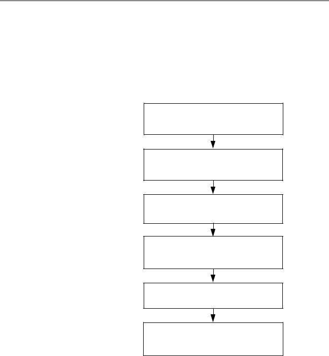
1-4 Basic Operating Procedure
1-4-1 Overview
The following diagram provides an overview of the installation procedures. For experienced installation engineers, this may provide sufficient information. For others, cross-references are made to various sections of this manual where more explicit information is given.
Mount the GRT1-PRT PROFIBUS Unit and
the SmartSlice I/O Units
(See section 2-2 Installing the GRT1-PRT Unit)
Wire the GRT1-PRT PROFIBUS Unit and the
SmartSlice I/O Units
(See section 2-3 Wiring the GRT1-PRT)
Setup the PROFIBUS network
(See section 2-4 Setting up a PROFIBUS Network)
Power up the GRT1-PRT and Perform initial setup (See section 3-3 Setup the GRT1-PRT Configuration)
Configure the PROFIBUS DP Master Unit (See section 3-3 Setup the GRT1-PRT Configuration)
PROFIBUS DP starts communicating, confirmed by the COMM LED continuously
lit. Check status of other LED Indicators (See section 3-4 Operating the Network)
9

Basic Operating Procedure |
Section 1-4 |
1-4-2 Preparations for Use
The following procedure shows the basic steps required before using the
PROFIBUS Communication Unit and the SmartSlice I/O Units.
Initial Setup Procedure
1,2,3... 1. Mount the GRT1-PRT Unit and the SmartSlice I/O system on the DIN rail The maximum number of SmartSlice I/O Units can be 64.
2.Wire the SmartSlice I/O Units and the GRT1-PRT Unit’s power supply.
3.Wire the PROFIBUS network, to connect the Unit to the PROFIBUS Master Unit.
4.Set the rotary switches on the front of the GRT1-PRT to the desired PROFIBUS address.
5.Turn ON the power to the Unit and the I/O.
6.Turn ON (from OFF to ON) DIP switch 1 on the front of the PROFIBUS Communication Unit. When switch 1 is turned ON, the existing SmartSlice I/O Unit configuration (connection order and I/O size) is registered in the PROFIBUS Communication Unit as a registered table. After the table is registered, leave pin 1 ON to enable the table.
Note The next time the power is turned ON, the actual SmartSlice I/O Unit configuration at power on is automatically compared to the registered table. Any SmartSlice I/O Units that do not match the registered table (connection order or I/O size) will not participate in I/O communication. I/O communication will start with the other SmartSlice I/O Units.
Configuration Procedure Use the following procedure to configure the PROFIBUS Master Unit for communication with the PROFIBUS Communication Unit, using the Cx-Profibus FDT Container program and the GRT1-PRT DTM:
1,2,3... 1. In Cx-Profibus, create a network and define the parameters and I/O configurations for the PROFIBUS Master Unit settings and the allocated slave devices. Determine the baud rate and the bus parameter setup. Make sure that the “Go to OPERATE mode “option is selected, to force the Unit to OPERATE mode upon a PLC mode change to RUN / MONITOR mode.
2.Download the network configuration to the PROFIBUS Master Unit. After downloading the configuration, Cx-Profibus will restart the PROFIBUS DP Master Unit.
3.After restarting the PROFIBUS DP Master Unit it will automatically start communication.
10
SECTION 2
Installation and Wiring
This section shows the GRT1-series PROFIBUS Communication Unit and identifies its controls and indicators. It contains the procedures for installing and wiring the Communication Unit as well as the GRT1-series SmartSlice I/O Units. It also contains the procedures for setting up the PROFIBUS network.
2-1 |
Unit Components . . . . . . . . . . . . . . . . . . . . . . . . . . . . . . . . . . . . . . . . . . . . . . |
12 |
|
|
2-1-1 |
Nomenclature . . . . . . . . . . . . . . . . . . . . . . . . . . . . . . . . . . . . . . . . . . |
12 |
|
2-1-2 |
LED Indicators . . . . . . . . . . . . . . . . . . . . . . . . . . . . . . . . . . . . . . . . . |
12 |
|
2-1-3 |
Switch Settings . . . . . . . . . . . . . . . . . . . . . . . . . . . . . . . . . . . . . . . . . |
13 |
|
2-1-4 |
Power Supply Connector . . . . . . . . . . . . . . . . . . . . . . . . . . . . . . . . . |
15 |
|
2-1-5 |
PROFIBUS Connector . . . . . . . . . . . . . . . . . . . . . . . . . . . . . . . . . . . |
15 |
2-2 |
Installing the GRT1-PRT Unit . . . . . . . . . . . . . . . . . . . . . . . . . . . . . . . . . . . . |
16 |
|
|
2-2-1 |
Handling Precautions . . . . . . . . . . . . . . . . . . . . . . . . . . . . . . . . . . . . |
16 |
|
2-2-2 Installation on a DIN Rail. . . . . . . . . . . . . . . . . . . . . . . . . . . . . . . . . |
16 |
|
|
2-2-3 Connecting the PROFIBUS Unit and SmartSlice I/O Units. . . . . . . |
18 |
|
|
2-2-4 Connecting Additional SmartSlice I/O Units . . . . . . . . . . . . . . . . . . |
18 |
|
2-3 |
Wiring the GRT1-PRT . . . . . . . . . . . . . . . . . . . . . . . . . . . . . . . . . . . . . . . . . . |
20 |
|
|
2-3-1 Connecting the SmartSlice I/O System Power Supply. . . . . . . . . . . |
20 |
|
|
2-3-2 |
Wiring Methods . . . . . . . . . . . . . . . . . . . . . . . . . . . . . . . . . . . . . . . . |
21 |
|
2-3-3 |
Connecting the Turnback Units . . . . . . . . . . . . . . . . . . . . . . . . . . . . |
23 |
2-4 Setting up a PROFIBUS Network. . . . . . . . . . . . . . . . . . . . . . . . . . . . . . . . . . |
24 |
||
|
2-4-1 |
Network Structure. . . . . . . . . . . . . . . . . . . . . . . . . . . . . . . . . . . . . . . |
24 |
|
2-4-2 |
Bus Termination . . . . . . . . . . . . . . . . . . . . . . . . . . . . . . . . . . . . . . . . |
26 |
|
2-4-3 |
PROFIBUS Cable Connector . . . . . . . . . . . . . . . . . . . . . . . . . . . . . . |
27 |
|
2-4-4 |
Shielding Precautions . . . . . . . . . . . . . . . . . . . . . . . . . . . . . . . . . . . . |
27 |
2-5 |
Installation of Configuration Software . . . . . . . . . . . . . . . . . . . . . . . . . . . . . . |
28 |
|
|
2-5-1 |
Installation Requirements . . . . . . . . . . . . . . . . . . . . . . . . . . . . . . . . . |
28 |
|
2-5-2 |
Installation Procedure . . . . . . . . . . . . . . . . . . . . . . . . . . . . . . . . . . . . |
28 |
|
2-5-3 |
GRT1-PRT GSD File . . . . . . . . . . . . . . . . . . . . . . . . . . . . . . . . . . . . |
29 |
11
Loading...