


Cat. No. H078-E1-03C
E5CK
Digital Controller
USER’S MANUAL

E5CK
Digital Controller
User's Manual
Cat. No. H078-E1-03C

Terms and Conditions of Sale
1.Offer; Acceptance. These terms and conditions (these "Terms") are deemed part of all quotes, agreements, purchase orders, acknowledgments, price lists, catalogs, manuals, brochures and other documents, whether electronic or in writing, relating to the sale of products or services (collectively, the "Products") by Omron Electronics LLC and its subsidiary companies (“Omron”). Omron objects to any terms or conditions proposed in Buyer’s purchase order or other documents which are inconsistent with, or in addition to, these Terms.
2.Prices; Payment Terms. All prices stated are current, subject to change without notice by Omron. Omron reserves the right to increase or decrease prices on any unshipped portions of outstanding orders. Payments for Products are due net 30 days unless otherwise stated in the invoice.
3.Discounts. Cash discounts, if any, will apply only on the net amount of invoices sent to Buyer after deducting transportation charges, taxes and duties, and will be allowed only if (i) the invoice is paid according to Omron’s payment terms and (ii) Buyer has no past due amounts.
4.Interest. Omron, at its option, may charge Buyer 1-1/2% interest per month or the maximum legal rate, whichever is less, on any balance not paid within the stated terms.
5.Orders. Omron will accept no order less than $200 net billing.
6.Governmental Approvals. Buyer shall be responsible for, and shall bear all costs involved in, obtaining any government approvals required for the importation or sale of the Products.
7.Taxes. All taxes, duties and other governmental charges (other than general real property and income taxes), including any interest or penalties thereon, imposed directly or indirectly on Omron or required to be collected directly or indirectly by Omron for the manufacture, production, sale, delivery, importation, consumption or use of the Products sold hereunder (including customs duties and sales, excise, use, turnover and license taxes) shall be charged to and remitted by Buyer to Omron.
8.Financial. If the financial position of Buyer at any time becomes unsatisfactory to Omron, Omron reserves the right to stop shipments or require satisfactory security or payment in advance. If Buyer fails to make payment or otherwise comply with these Terms or any related agreement, Omron may (without liability and in addition to other remedies) cancel any unshipped portion of Products sold hereunder and stop any Products in transit until Buyer pays all amounts, including amounts payable hereunder, whether or not then due, which are owing to it by Buyer. Buyer shall in any event remain liable for all unpaid accounts.
9.Cancellation; Etc. Orders are not subject to rescheduling or cancellation unless Buyer indemnifies Omron against all related costs or expenses.
10.Force Majeure. Omron shall not be liable for any delay or failure in delivery resulting from causes beyond its control, including earthquakes, fires, floods, strikes or other labor disputes, shortage of labor or materials, accidents to machinery, acts of sabotage, riots, delay in or lack of transportation or the requirements of any government authority.
11.Shipping; Delivery. Unless otherwise expressly agreed in writing by Omron:
a.Shipments shall be by a carrier selected by Omron; Omron will not drop ship except in “break down” situations.
b.Such carrier shall act as the agent of Buyer and delivery to such carrier shall constitute delivery to Buyer;
c.All sales and shipments of Products shall be FOB shipping point (unless otherwise stated in writing by Omron), at which point title and risk of loss shall pass from Omron to Buyer; provided that Omron shall retain a security interest in the Products until the full purchase price is paid;
d.Delivery and shipping dates are estimates only; and
e.Omron will package Products as it deems proper for protection against normal handling and extra charges apply to special conditions.
12.Claims. Any claim by Buyer against Omron for shortage or damage to the Products occurring before delivery to the carrier must be presented in writing to Omron within 30 days of receipt of shipment and include the original transportation bill signed by the carrier noting that the carrier received the Products from Omron in the condition claimed.
13.Warranties. (a) Exclusive Warranty. Omron’s exclusive warranty is that the Products will be free from defects in materials and workmanship for a period of twelve months from the date of sale by Omron (or such other period expressed in writing by Omron). Omron disclaims all other warranties, express or implied.
(b) Limitations. OMRON MAKES NO WARRANTY OR REPRESENTATION, EXPRESS OR IMPLIED, ABOUT NON-INFRINGEMENT, MERCHANTABIL-
ITY OR FITNESS FOR A PARTICULAR PURPOSE OF THE PRODUCTS. BUYER ACKNOWLEDGES THAT IT ALONE HAS DETERMINED THAT THE PRODUCTS WILL SUITABLY MEET THE REQUIREMENTS OF THEIR INTENDED USE. Omron further disclaims all warranties and responsibility of any type for claims or expenses based on infringement by the Products or otherwise of any intellectual property right. (c) Buyer Remedy. Omron’s sole obligation hereunder shall be, at Omron’s election, to (i) replace (in the form originally shipped with Buyer responsible for labor charges for removal or replacement thereof) the non-complying Product, (ii) repair the non-complying Product, or (iii) repay or credit Buyer an amount equal to the purchase price of the non-complying Product; provided that in no event shall Omron be responsible for warranty, repair, indemnity or any other claims or expenses regarding the Products unless Omron’s analysis confirms that the Products were properly handled, stored, installed and maintained and not subject to contamination, abuse, misuse or inappropriate modification. Return of any Products by Buyer must be approved in writing by Omron before shipment. Omron Companies shall not be liable for the suitability or unsuitability or the results from the use of Products in combination with any electrical or electronic components, circuits, system assemblies or any other materials or substances or environments. Any advice, recommendations or information given orally or in writing, are not to be construed as an amendment or addition to the above warranty. See http://oeweb.omron.com or contact your Omron representative for published information.
14.Limitation on Liability; Etc. OMRON COMPANIES SHALL NOT BE LIABLE FOR SPECIAL, INDIRECT, INCIDENTAL, OR CONSEQUENTIAL DAMAGES, LOSS OF PROFITS OR PRODUCTION OR COMMERCIAL LOSS IN ANY WAY CONNECTED WITH THE PRODUCTS, WHETHER SUCH CLAIM IS BASED IN CONTRACT, WARRANTY, NEGLIGENCE OR STRICT LIABILITY. Further, in no event shall liability of Omron Companies exceed the individual price of the Product on which liability is asserted.
15.Indemnities. Buyer shall indemnify and hold harmless Omron Companies and their employees from and against all liabilities, losses, claims, costs and expenses (including attorney's fees and expenses) related to any claim, investigation, litigation or proceeding (whether or not Omron is a party) which arises or is alleged to arise from Buyer's acts or omissions under these Terms or in any way with respect to the Products. Without limiting the foregoing, Buyer (at its own expense) shall indemnify and hold harmless Omron and defend or settle any action brought against such Companies to the extent based on a claim that any Product made to Buyer specifications infringed intellectual property rights of another party.
16.Property; Confidentiality. Any intellectual property in the Products is the exclusive property of Omron Companies and Buyer shall not attempt to duplicate it in any way without the written permission of Omron. Notwithstanding any charges to Buyer for engineering or tooling, all engineering and tooling shall remain the exclusive property of Omron. All information and materials supplied by Omron to Buyer relating to the Products are confidential and proprietary, and Buyer shall limit distribution thereof to its trusted employees and strictly prevent disclosure to any third party.
17.Export Controls. Buyer shall comply with all applicable laws, regulations and licenses regarding (i) export of products or information; (iii) sale of products to “forbidden” or other proscribed persons; and (ii) disclosure to non-citizens of regulated technology or information.
18.Miscellaneous. (a) Waiver. No failure or delay by Omron in exercising any right and no course of dealing between Buyer and Omron shall operate as a waiver of rights by Omron. (b) Assignment. Buyer may not assign its rights hereunder without Omron's written consent. (c) Law. These Terms are governed by the law of the jurisdiction of the home office of the Omron company from which Buyer is purchasing the Products (without regard to conflict of law principles). (d) Amendment. These Terms constitute the entire agreement between Buyer and Omron relating to the Products, and no provision may be changed or waived unless in writing signed by the parties. (e) Severability. If any provision hereof is rendered ineffective or invalid, such provision shall not invalidate any other provision. (f) Setoff. Buyer shall have no right to set off any amounts against the amount owing in respect of this invoice. (g) Definitions. As used herein, “including” means “including without limitation”; and “Omron Companies” (or similar words) mean Omron Corporation and any direct or indirect subsidiary or affiliate thereof.
Certain Precautions on Specifications and Use
1.Suitability of Use. Omron Companies shall not be responsible for conformity with any standards, codes or regulations which apply to the combination of the Product in the Buyer’s application or use of the Product. At Buyer’s request, Omron will provide applicable third party certification documents identifying ratings and limitations of use which apply to the Product. This information by itself is not sufficient for a complete determination of the suitability of the Product in combination with the end product, machine, system, or other application or use. Buyer shall be solely responsible for determining appropriateness of the particular Product with respect to Buyer’s application, product or system. Buyer shall take application responsibility in all cases but the following is a
non-exhaustive list of applications for which particular attention must be given:
(i)Outdoor use, uses involving potential chemical contamination or electrical interference, or conditions or uses not described in this document.
(ii)Use in consumer products or any use in significant quantities.
(iii)Energy control systems, combustion systems, railroad systems, aviation systems, medical equipment, amusement machines, vehicles, safety equip-
ment, and installations subject to separate industry or government regulations. (iv) Systems, machines and equipment that could present a risk to life or property. Please know and observe all prohibitions of use applicable to this Product.
NEVER USE THE PRODUCT FOR AN APPLICATION INVOLVING SERIOUS RISK TO LIFE OR PROPERTY OR IN LARGE QUANTITIES WITHOUT ENSURING THAT THE SYSTEM AS A WHOLE HAS BEEN DESIGNED TO
ADDRESS THE RISKS, AND THAT THE OMRON’S PRODUCT IS PROPERLY RATED AND INSTALLED FOR THE INTENDED USE WITHIN THE OVERALL EQUIPMENT OR SYSTEM.
2.Programmable Products. Omron Companies shall not be responsible for the user’s programming of a programmable Product, or any consequence thereof.
3.Performance Data. Data presented in Omron Company websites, catalogs and other materials is provided as a guide for the user in determining suitability and does not constitute a warranty. It may represent the result of Omron’s test conditions, and the user must correlate it to actual application requirements. Actual performance is subject to the Omron’s Warranty and Limitations of Liability.
4.Change in Specifications. Product specifications and accessories may be changed at any time based on improvements and other reasons. It is our practice to change part numbers when published ratings or features are changed, or when significant construction changes are made. However, some specifications of the Product may be changed without any notice. When in doubt, special part numbers may be assigned to fix or establish key specifications for your application. Please consult with your Omron’s representative at any time to confirm actual specifications of purchased Product.
5.Errors and Omissions. Information presented by Omron Companies has been checked and is believed to be accurate; however, no responsibility is assumed for clerical, typographical or proofreading errors or omissions.


 Preface
Thank you for your purchase of your E5CK compact, intelligent digital controller. The E5CK allows the user to carry out the following:
•Select from many types of temperature and analog input (multiple input)
•Select output functions such as control output or alarm (output assignment)
•Use two setpoints (multi#SP function)
•Monitor the control loop by LBA (Loop Break Alarm)
•Use the communications function
•Calibrate input or transfer output
•It also features a watertight construction (NEMA4: equivalent to IP66)
This User's Manual describes how to use the E5CK compact, high#function digital con# troller.
Before using your E5CK, thoroughly read and understand this manual in order to ensure correct use.
About this manual
E OMRON, 1995
(1)All rights reserved. No part of this publication may be reproduced, stored in a retrieval system, or transmitted, in any form, or by any means, mechanical, electronic, photocopying, recording, recording, or otherwise, without the prior written permission of OMRON.
(2)No patent liability is assumed with respect to the use of the information contained herein.
(3)Moreover, because OMRON is constantly striving to improve its high-quality products, the information in this manual is subject to change without notice. Every precaution has been taken in the preparation of this manual. Nevertheless, OMRON assumes no responsibility for errors or omissions. Neither is any liability assumed for damages resulting from the use of the information contained in this publication.
I


 Conventions Used in This Manual
JHow to Read Display Symbols
The following tables show the correspondence between the symbols displayed on the displays and alphabet characters.
A B C D E F G H I J K L M
N O P Q R S T U V W X Y Z
J“Reference” mark
This mark indicates that extra, useful information follows, such as supplementary explanations and how to apply functions.
JNotice:
OMRON products are manufactured for use according to proper procedures by a qualified opera# tor and only for the purposes described in this manual.
The following conventions are used to indicate and classify precautions in this manual. Always heed the information provided with them. Failure to heed precautions can result in injury to people or damage to the product.
 DANGER
 WARNING
 Caution
Indicates information that, if not heeded, is likely to result in loss of life or serious injury.
Indicates information that, if not heeded, could possibly result in loss of life or serious injury.
Indicates information that, if not heeded, could result in relatively seri# ous or minor injury, damage to the product, or faulty operation.
JOMRON Product References
All OMRON products are capitalized in this manual. The word •Unit" is also capitalized when it refers to an OMRON product, regardless of whether or not it appears in the proper name of the product.
The abbreviation •Ch," which appears in some displays and on some OMRON products, often means •word" and is abbreviated •Wd" in documentation in this sense.
The abbreviation •PC" means Programmable Controller and is not used as an abbreviation for anything else.
II

JHow this Manual is Organized
Purpose |
|
Title |
|
Description |
|
Learning about the gen- |
Chapter 1 |
Introduction |
This chapter describes the fea# |
||
eral features of the E5CK |
|
|
tures |
of the E5CK, names of |
|
|
|
parts, and typical functions. |
|||
|
|
|
|||
Setting up the E5CK |
Chapter 2 |
Preparations |
This chapter describes the opera# |
||
|
|
|
tions that you must carry out |
||
|
|
|
(e.g. |
installation, wiring and |
|
|
|
|
switch settings) before you can |
||
|
|
|
use the E5CK. |
||
Basic E5CK operations |
Chapter 3 |
Basic Operation |
These chapters describe how to |
||
|
Chapter 5 Parameters |
use the front panel keys and how |
|||
|
|
|
to view the display when setting |
||
|
|
|
the parameters of the major func# |
||
|
|
|
tions for the E5CK. |
||
|
|
|
|
|
|
Applied E5CK operations
Communications with a host computer
Calibration
Troubleshooting
Chapter 4 Applied Operation |
These |
chapters describe the |
||
Chapter 5 |
Parameters |
important functions of the E5CK |
||
|
|
and how to use the parameters |
||
|
|
for making full use of the E5CK. |
||
Chapter 6 |
Using the Commu# |
This |
chapter mainly describes |
|
nications Function |
the communications commands, |
|||
|
|
and gives program examples. |
||
Chapter 4 |
Applied Operation |
This chapter describes how the |
||
/ 4.5 Calibration |
user should calibrate the E5CK. |
|||
Chapter 7 |
Troubleshooting |
This chapter describes what to do |
||
|
|
if any problems occur. |
||
|
|
|
|
|
III

Pay Attention to the Following when Installing this Controller
F If you remove the controller from its case, never touch nor apply shock to the electronic parts inside.
F Do not cover the top and bottom of the controller. (Ensure sufficient space around the controller to allow heat to escape.)
F Use a voltage (AC100#240V or AC/DC24V
 at 50 to 60 Hz). At power ON, the pre# scribed voltage level must be attained within two seconds.
F When wiring input or output lines to your controller, keep the following points in mind to reduce the influence from inductive noise:
C• Allow adequate space between the high voltage/current power lines and the input/out# put lines.
C• Avoid parallel or common wiring with high voltage sources and power lines carrying large currents.
C• Using separating pipes, duct, and shielded line is also useful in protecting the controller, and its lines form inductive noise.
F Allow as much space as possible between the controller and devices that generate a pow# erful, high frequency (high#frequency welders, high#frequency sewing machines, and so forth) or surge. These devices may cause malfunctions.
F If there is a large power#generating peripheral device and any of its lines, attach a surge suppressor or noise filter to the device to stop the noise affecting the controller system. In particular, motors, transformers, solenoids and magnetic coils have an inductance component, and therefore can generate very strong noises.
F When mounting a noise filter, be sure to first check the filter's voltage and current capacity, then mount the filter as close as possible to the controller.
F Do not use the controller in places where icing, condensation, dust, corrosive gas (espe# cially sulfurized gas or ammonia gas), shock, vibration, splashing liquid, or oil atmo# sphere occur. Also, avoid places where the controller can be subjected to intense heat radiation (like from a furnace) or sudden temperature changes.
F Ambient temperature must be kept between #10_C to 55_C. Ambient humidity must be kept between 35%RH to 85%RH (with no icing or condensation). If the controller is installed inside a control board, the ambient temperature must be kept under 55_C, including the temperature around the controller. If the controller is subjected to heat radiation, use a fan to cool the surface of the controller to under 55_C.
F Store the controller at an ambient temperature between #25_C to 65_C. The ambient humidity must be between 35%RH to 85%RH (with no icing or condensation).
F Never place heavy objects on, or apply pressure to the controller that may cause it to deform and deterioration during use or storage.
F Avoid using the controller in places near a radio, television set, or wireless installation. These devices can cause radio disturbances which adversely affect the performance of the controller.
IV


 Table of Contents
|
. . . . . . . . . . . . . . . . . . . . . . . . . . . . . . . . . . . . . .Preface |
I |
|
Conventions Used in This Manual . . . . . . . . . . . . . . . |
II |
|
Pay Attention to the Following when Installing |
|
|
this Controller . . . . . . . . . . . . . . . . . . . . . . . . . . . . . . . . . |
IV |
CHAPTER 1 INTRODUCTION . . . . . . . . . . . . . . . . . . . . . . . . . . |
1–1 |
|
|
This chapter introduces the E5CK. First-time users should read this chapter with- |
|
|
out fail. |
|
|
For details on how to use the controller and parameter settings, see Chapters 2 |
|
|
onwards. |
|
1.1 |
Names of parts . . . . . . . . . . . . . . . . . . . . . . . . . . . . . . . . . . . . . . . . . . |
1–2 |
1.2 |
Input and Output . . . . . . . . . . . . . . . . . . . . . . . . . . . . . . . . . . . . . . . . . |
1–4 |
1.3 |
Parameters and Menus . . . . . . . . . . . . . . . . . . . . . . . . . . . . . . . . . . . |
1–6 |
1.4 |
About the Communications Function . . . . . . . . . . . . . . . . . . . . . . . |
1–9 |
1.5 |
About Calibration . . . . . . . . . . . . . . . . . . . . . . . . . . . . . . . . . . . . . . . . |
1–10 |
CHAPTER 2 PREPARATIONS . . . . . . . . . . . . . . . . . . . . . . . . . . |
2–1 |
|
|
This chapter describes the operations you should carry out before turning the |
|
|
E5CK ON. |
|
2.1 |
Setting up . . . . . . . . . . . . . . . . . . . . . . . . . . . . . . . . . . . . . . . . . . . . . . . |
2–2 |
2.2 |
Installation . . . . . . . . . . . . . . . . . . . . . . . . . . . . . . . . . . . . . . . . . . . . . . |
2–4 |
2.3 |
Wiring Terminals . . . . . . . . . . . . . . . . . . . . . . . . . . . . . . . . . . . . . . . . . |
2–6 |
CHAPTER 3 BASIC OPERATION . . . . . . . . . . . . . . . . . . . . . . . . |
3–1 |
|
|
This chapter describes an actual example for understanding the basic operation |
|
|
of the E5CK. |
|
3.1 |
Control Example . . . . . . . . . . . . . . . . . . . . . . . . . . . . . . . . . . . . . . . . . |
3–2 |
3.2 |
Setting Input Specifications . . . . . . . . . . . . . . . . . . . . . . . . . . . . . . . |
3–3 |
3.3 |
Setting Output Specifications . . . . . . . . . . . . . . . . . . . . . . . . . . . . . . |
3–5 |
3.4 |
Setting Alarm Type . . . . . . . . . . . . . . . . . . . . . . . . . . . . . . . . . . . . . . . |
3–7 |
3.5 |
Protect Mode . . . . . . . . . . . . . . . . . . . . . . . . . . . . . . . . . . . . . . . . . . . . |
3–10 |
3.6 |
Starting and Stopping Operation . . . . . . . . . . . . . . . . . . . . . . . . . . . |
3–11 |
3.7 |
Adjusting Control Operation . . . . . . . . . . . . . . . . . . . . . . . . . . . . . . . |
3–12 |
CHAPTER 4 APPLIED OPERATION . . . . . . . . . . . . . . . . . . . . . |
4–1 |
|
|
This chapter describes each of the parameters required for making full use of the |
|
|
features of the E5CK. Read this chapter while referring to the parameter descrip- |
|
|
tions in chapter 5. |
|
4.1 |
Selecting the Control Method . . . . . . . . . . . . . . . . . . . . . . . . . . . . . . |
4–2 |
4.2 |
Operating Condition Restrictions . . . . . . . . . . . . . . . . . . . . . . . . . . . |
4–4 |
4.3 |
How to Use Option Functions . . . . . . . . . . . . . . . . . . . . . . . . . . . . . |
4–7 |
4.4 |
LBA . . . . . . . . . . . . . . . . . . . . . . . . . . . . . . . . . . . . . . . . . . . . . . . . . . . . |
4–9 |
4.5 |
Calibration . . . . . . . . . . . . . . . . . . . . . . . . . . . . . . . . . . . . . . . . . . . . . . |
4–11 |
CHAPTER 5 PARAMETERS . . . . . . . . . . . . . . . . . . . . . . . . . . . . |
5–1 |
This chapter describes the parameters of the E5CK. Use this chapter as a reference guide.
Conventions Used in this Chapter . . . . . . . . . . . . . . . . . . . . . . . . . . . . . . 5–2 Protect Mode . . . . . . . . . . . . . . . . . . . . . . . . . . . . . . . . . . . . . . . . . . . . . . . . 5–3 Manual Mode . . . . . . . . . . . . . . . . . . . . . . . . . . . . . . . . . . . . . . . . . . . . . . . . 5–5 Level 0 Mode . . . . . . . . . . . . . . . . . . . . . . . . . . . . . . . . . . . . . . . . . . . . . . . . 5–6 Level 1 Mode . . . . . . . . . . . . . . . . . . . . . . . . . . . . . . . . . . . . . . . . . . . . . . . . 5–9 Level 2 Mode . . . . . . . . . . . . . . . . . . . . . . . . . . . . . . . . . . . . . . . . . . . . . . . . 5–15 Setup Mode . . . . . . . . . . . . . . . . . . . . . . . . . . . . . . . . . . . . . . . . . . . . . . . . . 5–21 Expansion Mode . . . . . . . . . . . . . . . . . . . . . . . . . . . . . . . . . . . . . . . . . . . . . 5–27 Option Mode . . . . . . . . . . . . . . . . . . . . . . . . . . . . . . . . . . . . . . . . . . . . . . . . . 5–32 Calibration Mode . . . . . . . . . . . . . . . . . . . . . . . . . . . . . . . . . . . . . . . . . . . . . 5–36
CHAPTER 6 USING THE COMMUNICATIONS FUNCTION . 6–1
This chapter mainly describes communications with a host computer and communications commands.
6.1 |
Outline of the Communications Function . . . . . . . . . . . . . . . . . . . . |
6–2 |
6.2 |
Preparing for Communications . . . . . . . . . . . . . . . . . . . . . . . . . . . . |
6–3 |
6.3 |
Command Configuration . . . . . . . . . . . . . . . . . . . . . . . . . . . . . . . . . . |
6–5 |
6.4 |
Commands and Responses . . . . . . . . . . . . . . . . . . . . . . . . . . . . . . . |
6–6 |
6.5 |
How to Read Communications Error Information . . . . . . . . . . . . . |
6–10 |
6.6 |
Program Example . . . . . . . . . . . . . . . . . . . . . . . . . . . . . . . . . . . . . . . |
6–12 |
CHAPTER 7 TROUBLESHOOTING . . . . . . . . . . . . . . . . . . . . . . |
7–1 |
|
|
This chapter describes how to find out and remedy the cause if the E5CK does |
|
|
not function properly. |
|
7.1 |
Initial Checks . . . . . . . . . . . . . . . . . . . . . . . . . . . . . . . . . . . . . . . . . . . . |
7–2 |
7.2 |
How to Use the Error Display . . . . . . . . . . . . . . . . . . . . . . . . . . . . . . |
7–3 |
7.3 |
How to Use Error Output . . . . . . . . . . . . . . . . . . . . . . . . . . . . . . . . . . |
7–5 |
7.4 |
Checking Operation Restrictions . . . . . . . . . . . . . . . . . . . . . . . . . . . |
7–6 |
APPENDIX
SPECIFICATIONS . . . . . . . . . . . . . . . . . . . . . . . . |
A–2 |
CONTROL BLOCK DIAGRAM . . . . . . . . . . . . . . |
A–5 |
SETTING LIST . . . . . . . . . . . . . . . . . . . . . . . . . . . |
A–6 |
PARAMETER OPERATIONS LIST . . . . . . . . . . |
A–8 |
FUZZY SELF–TUNING . . . . . . . . . . . . . . . . . . . . |
A–10 |
MODEL LIST . . . . . . . . . . . . . . . . . . . . . . . . . . . . . |
A–13 |
X FORMAT . . . . . . . . . . . . . . . . . . . . . . . . . . . . . . . |
A–14 |
ASCII CODE LIST . . . . . . . . . . . . . . . . . . . . . . . . |
A–17 |
INDEX |
|
REVISION HISTORY
CHAPTER 1 INTRODUCTION 

CHAPTER1
INTRODUCTION
This chapter introduces the E5CK. First#time users should read this chapter without fail.
For details on how to use the controller and parameter settings, see Chapters 2 onwards.
1.1 |
Names of parts . . . . . . . . . . . . . . . . . . . . . . . . |
1-2 |
|
Main parts . . . . . . . . . . . . . . . . . . . . . . . . . . . . |
1-2 |
|
Front panel . . . . . . . . . . . . . . . . . . . . . . . . . . . |
1-2 |
|
About the displays . . . . . . . . . . . . . . . . . . . . . |
1-3 |
|
How to use keys . . . . . . . . . . . . . . . . . . . . . . . |
1-3 |
1.2 |
Input and Output . . . . . . . . . . . . . . . . . . . . . . |
1-4 |
|
Input . . . . . . . . . . . . . . . . . . . . . . . . . . . . . . . . . |
1-4 |
|
Output . . . . . . . . . . . . . . . . . . . . . . . . . . . . . . . . |
1-5 |
1.3 |
Parameters and Menus . . . . . . . . . . . . . . . . . |
1-6 |
|
Parameter types . . . . . . . . . . . . . . . . . . . . . . . |
1-6 |
|
Selecting modes . . . . . . . . . . . . . . . . . . . . . . . . |
1-7 |
|
Selecting parameters . . . . . . . . . . . . . . . . . . . |
1-8 |
|
Fixing settings . . . . . . . . . . . . . . . . . . . . . . . . . |
1-8 |
1.4 |
About the Communications Function . . . . |
1-9 |
1.5 |
About Calibration . . . . . . . . . . . . . . . . . . . . . . |
1-10 |
1–1


 CHAPTER 1 INTRODUCTION
1.1 Names of parts
JMain parts
Terminals
P 2-6
Output unit
P 2-3
Rear case
Input type jumper connector P 2-2
Option unit
P 2-3
Front panel
JFront panel
Operation indicators
OUT1
OUT2
SUB1
MANU
STOP
RMT AT
SV
OUT1
PV |
No.1 display |
|
No.2 display
|
OUT2 MANU STOP RMT AT |
SUB1 |
A/M key |
A M |
|
A/M |
|
E5CK |
|
|
Display key |
Down key |
Up key |
1–2
|
|
1.1 Names of parts |
|
|
|
|
|
JAbout the displays |
|
|
|
F No.1 display |
Displays the process value or parameter symbols. |
||
F No.2 display |
Displays the set point, manipulated variable or parameter settings. |
||
F Operation indica- |
C• OUT1 |
: Lits when the pulsed output function assigned to “control |
|
tors |
|
output 1" is ON. |
|
|
C• OUT2 |
: Lits when the output function assigned to “control output 2" |
|
|
|
is ON. |
|
|
C• SUB1 |
: Lits when the output function assigned to “auxiliary output |
|
|
|
1" is ON. |
|
|
C• MANU |
: Lits in the manual operation mode. |
|
|
C• STOP |
: Lits when operation has stopped. |
|
|
C• RMT |
: Lits during remote operation. |
|
|
C• AT |
: Flashes during auto#tuning. |
|
JHow to use keys
F  key
key
F  key
key
F 
 key
key
The following describes basic key operations.
Each press of this key switches between the auto and manual operations.
The functions of this key change according to how long it is pressed. If the key is pressed for less than one second, the parameters are switched. If the key is pressed for one second or more, the menu display appears. In key operations from here on, “press the key" refers to pressing the key for less than one second.
For details on parameter switching and menu display items, see page 1-7.
Each press of the  key increments or advances the values or settings on the No.2 display, while each press of the
  key decrements or returns the values or settings on the No.2 display.
Functions vary, for example, when the  key is held down simulta# neously with the display key, or a key is held down continuously. For details, see page 1#7. Also, chapters 3 and 4 describe examples using vari# ous key combinations.
1–3


 CHAPTER 1 INTRODUCTION
1.2 Input and Output
Temperature input
Voltage input
Current input
Event input
JInput
|
|
Control output |
Controller |
(heat) |
|
|
Control output |
|
Input type |
|
|
jumper |
|
(cool) |
|
|
Alarm 1 |
Alarm 3
LBA
Error 1
Error 2
The E5CK supports four inputs.
Control output 1
Control output 2
Auxiliary
output 1
Transfer
output 1
F Temperature input/Voltage input/Current input
C• Only one of temperature input, voltage input and current input can be selected and connected to the controller. The above figure shows temper# ature input connected to the controller.
C• The following input sensors can be connected for temperature input: Thermocouple: K, J, T, E, L, U, N, R, S, B, W, PLII
Platinum resistance thermometer: JPt100, Pt100
C• The following currents can be connected for current input: 4 to 20 mA, 0 to 20 mA
C• The following voltages can be connected for voltage input: 1 to 5 VDC, 0 to 5 VDC, 0 to 10 VDC
F Event input |
When using event input, add on the input unit (E53-CKB). |
|
You can select from the following five event inputs: |
|
Multi#SP |
|
Run/Stop |
|
Auto/Manual |
1–4

1.2 Input and Output 

JOutput
The E5CK supports the following four outputs. Control output 1
Control output 2
Auxiliary output 1
Transfer output
When using control outputs 1 and 2, set the output unit (sold separately).
Eight output units are available to suit the output circuit configuration.
When using transfer output, add on the communication unit (E53-CKF).
Note: The output functions of the E5CK do not operate for five seconds af# ter the E5CK is turned ON.
F Output assignments
F Transfer output
The E5CK supports the following eight output functions. Control output (heat)
Control output (cool)
Alarms 1 to 3
LBA
Error 1 (input error)
Error 2 (A/D converter error)
Assign these output functions to control outputs 1 and 2 and auxiliary out# put 1.
Only control output (heat), control output (cool), alarms 1 to 3, and LBA can be assigned to control outputs 1 and 2. Also, only alarms 1 to 3, LBA, and errors 1 and 2 can be assigned to auxiliary output 1.
In the example on the previous page, •control output (heat)" is assigned to •control output 1", •alarm 1" is assigned to •control output 2", and •alarm 2" is assigned to •auxiliary output 1". Accordingly, the configura# tion is such that heating control output is connected to control output 1, and alarm output is connected to control output 2 and auxiliary output 1.
In a heating and cooling control, assign •control output (cool)" to either of •control output 1" or •control output 2".
The E5CK supports the following five transfer outputs. Set point
Set point during SP ramp
Process value
Heating side manipulated variable
Cooling side manipulated variable
These transfer outputs can be output after being scaled. Setting of an upper limit value smaller than the lower limit value is allowed, so reverse scaling can also be carried out.
1–5


 CHAPTER 1 INTRODUCTION
1.3 Parameters and Menus
|
|
JParameter types |
E5CK parameters are distributed between the following nine modes. |
|
Protect mode |
|
Manual mode |
|
Level 0 mode |
|
Level 1 mode |
|
Level 2 mode |
|
Setup mode |
|
Expansion mode |
|
Option mode |
|
Calibration mode |
|
The settings of parameters in each of seven modes (excluding the protect |
|
mode and manual mode) can be checked and modified by selection on the |
|
menu display. |
F Protect mode
F Manual mode
F Level 0 mode
This mode is used to limit use of the menu and  keys. The protect func# tion is for preventing unwanted modification of parameters and switching between the auto and manual operation.
In this mode, the controller can be switched manual operation. The manipulated variable can be manipulated manually only in this mode.
Set the controller to this mode during normal operation. In this mode, you may change the set point during operation, and stop and start operation. You can also monitor (not change) the process value, ramp SP and manip# ulated variable.
F Level 1 mode |
This is the main mode for adjusting control. In this mode, you can execute |
|
AT (auto#tuning), and set alarm values, the control period and PID param# |
|
eters. |
F Level 2 mode |
This is the auxiliary mode for adjusting control. In this mode, you can set |
|
the parameters for limiting the manipulated variable and set point, switch |
|
between the remote and local modes, and set the loop break alarm (LBA), |
|
alarm hysteresis and the digital filter value of inputs. |
F Setup mode |
This is the mode for setting the basic specifications. In this mode, you can |
|
set parameters that must be checked or set before operation such as the |
|
input type, scaling, output assignments and direct/reverse operation. |
F Expansion mode |
This is the mode for setting expanded functions. In this mode, you can set |
|
ST (self#tuning), SP setting limiter, selection of advanced PID or ON/OFF |
|
control, specification of the standby sequence resetting method, initializa# |
|
tion of parameters, time for automatic return to the monitoring display. |
1–6

|
|
|
|
|
|
|
|
|
1.3 Parameters and Menus |
|
|
|
|
|
|
|
|
|
|
|
|
||
F Option mode |
This is the mode for setting option functions. You can select this mode only |
||||||||||
|
|
|
|
when the option unit is set in the controller. In this mode, you can set the |
|||||||
|
|
|
|
communications conditions, transfer output and event input parameters |
|||||||
|
|
|
|
to match the type of option unit set in the controller. |
|
|
|||||
F Calibration mode |
This mode is provided so that the user can calibrate inputs and transfer |
||||||||||
|
|
|
|
output. |
|
|
|
||||
|
|
|
|
When calibrating input, the selected input type is calibrated. Whereas, |
|||||||
|
|
|
|
transfer output can be calibrated only when the communications unit |
|||||||
|
|
|
|
(E53-CKF) is set in the controller. |
|
|
|
||||
JSelecting modes |
The following diagram shows the order in which modes are selected. |
||||||||||
|
|
|
|
|
|
|
|
Power ON |
|
|
|
|
|
|
|
|
|
|
|
|
A/M |
|
|
|
|
|
|
|
|
|
|
1 second min. |
1 second min. |
|
|
|
|
|
|
|
|
|
|
Level 0 mode |
|
Manual mode |
|
|
|
|
|
|
|
|
|
1 second min. |
|
A/M |
|
|
|
|
|
|
|
|
|
|
|||
|
|
|
|
|
|
|
|
|
|||
|
|
|
|
|
|||||||
|
|
|
|
|
|
|
|
Level 1 mode |
|
1 second min. |
|
|
|
|
|
|
|
|
|
|
|
||
|
|
|
|
|
|
|
|
1 second min. |
|
|
|
|
|
|
|
|
|
|
|
|
|
|
|
|
|
|
|
|
|
|
|
|
|
|
|
|
|
|
|
|
|
|
|
Level 2 mode |
A/M + |
A/M + |
|
1 second min.
1 second min.
1 second min.
1 second min.
1 second min. 1 second min.
Setup mode
Protect mode
Expansion
mode A/M +
1 second min.
Option mode
Calibration mode
F Menu display
F Level 0 to 2 modes
C• To select the menu display in any of the above modes (excluding the pro# tect mode and manual mode), press the  key for 1 second minimum. If you select the desired mode using the
  or
or  keys and press the
  key, the top parameter in the specified mode is displayed.
C• When you have selected the menu display, the previous mode is selected. For example, if you selected the menu display while in the level 0 mode, the No.2 display changes to [ ] as shown on the left.
C• Protected modes cannot be selected. Also, the menu display does not appear when modes are protected up to the level 1 mode.
C• If you select [ ] [
] [ ] or [
 ] in the menu display, the level 0, level 1 and level 2 modes, respectively, are selected.
C• These modes are selected with control still continuing.
1–7


 CHAPTER 1 INTRODUCTION
F Setup mode
F Expansion mode F Option mode
F Calibration mode
F Protect mode
F Manual mode
JSelecting parameters
C• If you select [CC ] [CC
] [CC ] [CC
] [CC ] or [CC
 ] in the menu display, the setup, expansion, option and calibration modes, respectively, are selected.
C• When these modes are selected, the control is reset. So, control outputs and auxiliary output are turned OFF. When another mode is selected while in these modes, reset is canceled.
C• To set the controller to the protect mode or to return to the level 0 mode from the protect mode, press the  key and
  key for 1 second mini# mun simultaneously.
C• To set the controller to the manual mode, press the  key for 1 second minimun in the level 0 to 2 mode. To return to the level 0 mode from the manual mode, press the
  key for 1 second minimum.
C• When not in the manual mode, each press of the  key switches the parameter.
C• If you press the  key when at the final parameter, the display returns to the first parameter.
Parameter |
Parameter |
Parameter |
Parameter |
1 |
2 |
3 |
n |
JFixing settings |
C• When you have changed a parameter setting, specify the parameter |
|||
|
using the |
or |
keys, and either leave the setting for at least two |
|
|
seconds or press the |
key. This fixes the setting. |
||
|
C• When another mode is selected, the content of the parameters before the |
|||
|
mode was selected is fixed. |
|
||
|
C• When turning the power OFF, you must first fix the settings and param# |
|||
|
eter contents (by pressing the |
key or selecting another mode). The |
||
|
settings and parameter contents are sometimes not changed by merely |
|||
|
pressing the |
or |
keys. |
|
1–8

1.4 About the Communications Function 

1.4 About the Communications Function
|
|
|
The E5CK can be provided with a communications function that allows |
|
you to check and set controller parameters from a host computer. If the |
|
communications function is required, add on the communications unit. |
|
For details on the communications function, refer to Chapter 6. |
F RS-232C |
When using the communications function on the RS-232C interface, add |
|
on the communications unit (E53-CK01). |
F RS-485 |
When using the communications function on the RS-485 interface, add |
|
on the communications unit (E53-CK03). |
1–9


 CHAPTER 1 INTRODUCTION
1.5 About Calibration
FCalibrating inputs
The E5CK controller is calibrated before shipment from the factory. So, the user need not calibrate the E5CK controller during regular use.
However, if the E5CK controller must be calibrated by the user, use the parameters provided for user to calibrate temperature input, analog input (voltage, current) and transfer output.
Also, note that calibration data is updated to the latest value each time the E5CK controller is calibrated. Calibration data set before shipment from the factory cannot be returned to after calibration by the user.
The input type selected in the parameter is the item to be calibrated. The E5CK is provided with the following four calibration parameters.
C• Thermocouple
C• Platinum resistance thermometer C• Current input
C• Voltage input
Two parameters are provided for thermocouple and voltage input.
F Calibrating transfer output
F Registering calibration data
Transfer output can be calibrated when the communications unit (E53-CKF) is added on.
When calibrating each item, the calibration data is temporarily regis# tered. This data can be registered as final calibration data only when all items have been newly calibrated. So, all items must be temporarily regis# tered when calibrating the E5CK controller.
When registering data, information regarding whether or not calibration has been carried out is also registered.
To calibrate these items, the user must prepare separate measuring devices and equipment. For details on handling these measuring devices and equipment, refer to the respective manuals.
For details, see 4.5 Calibration (page 4-11).
1–10
CHAPTER 2 PREPARATIONS 

CHAPTER2
PREPARATIONS
This chapter describes the operations you should carry out before turn# ing the E5CK ON.
2.1 |
Setting up . . . . . . . . . . . . . . . . . . . . . . . . . . . . . |
2-2 |
|
Draw#out . . . . . . . . . . . . . . . . . . . . . . . . . . . . . . |
2-2 |
|
Setting the input type . . . . . . . . . . . . . . . . . . |
2-2 |
|
Setting up the output unit . . . . . . . . . . . . . . |
2-3 |
|
Setting up the option unit . . . . . . . . . . . . . . . |
2-3 |
2.2 |
Installation . . . . . . . . . . . . . . . . . . . . . . . . . . . . |
2-4 |
|
Dimensions . . . . . . . . . . . . . . . . . . . . . . . . . . . . |
2-4 |
|
Panel cutout . . . . . . . . . . . . . . . . . . . . . . . . . . . |
2-4 |
|
Mounting . . . . . . . . . . . . . . . . . . . . . . . . . . . . . |
2-5 |
2.3 |
Wiring Terminals . . . . . . . . . . . . . . . . . . . . . . |
2-6 |
|
Terminal arrangement . . . . . . . . . . . . . . . . . |
2-6 |
|
Precautions when wiring . . . . . . . . . . . . . . . |
2-6 |
|
Wiring . . . . . . . . . . . . . . . . . . . . . . . . . . . . . . . . |
2-6 |
2–1

 CHAPTER 2 PREPARATIONS
2.1 Setting up
JDraw-out
This section describes how to set the input type jumper, and set up the out# put unit or option unit.
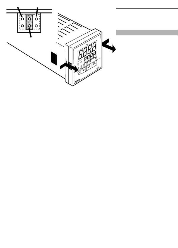
First, draw out the internal mechanism from the housing
(1)Pull out the internal mechanism while pressing the hooks on the left and right sides of the front panel.
(2)Draw out the internal mechanism towards you holding both sides of the front panel.
JSetting the input type
C• For details on the jumper connector position, see page 1#2.
C• Set the input type jumper connector to one of temperature input, voltage input or current input matched to the sensor connected to the input ter# minal.
I : Current input V : Voltage input
TC.PT : Temperature input
C• The factory setting is •TC/PT (temperature input)."
C• When removing or inserting the jumper connector, do not touch the pins directly with your fingers.
C• When you have set the jumper connector, insert the internal mechanism into the rear case.
C• When inserting the internal mechanism, push in until you hear the hooks on the front panel click into place.
2–2

|
|
2.1 Setting up |
|
|
|
|
|
|
|
JSetting up the output unit |
|
|
|
|
F Output unit list |
The following table shows the output units that can be set in the E5CK |
|
||
|
controller. |
|
|
|
|
|
|
|
|
|
Model |
Specifications |
|
|
|
(control output 1/control output 2) |
|
||
|
|
|
||
|
|
|
|
|
|
E53-R4R4 |
Relay/Relay |
|
|
|
E53-Q4R4 |
Voltage (NPN)/Relay |
|
|
|
E53-Q4HR4 |
Voltage (PNP)/Relay |
|
|
|
E53-C4R4 |
4 to 20 mA/Relay |
|
|
|
E53-C4DR4 |
0 to 20 mA/Relay |
|
|
|
E53-V44R4 |
0 to 10 V/Relay |
|
|
|
E53-Q4Q4 |
Voltage (NPN)/Voltage (NPN) |
|
|
|
E53-Q4HQ4H |
Voltage (PNP)/Voltage (PNP) |
|
|
|
|
|
|
|
F Setup
(1) Two rectangular holes for slotting are pro# vided on the power board (on right side of controller). Fit the two protrusions on the output unit into these two holes.
(2) With the output unit fitted into the power board, fit the output unit into the connector on the control board (on left side of control# ler).
JSetting up the option unit
F Option unit list |
The following table shows the option units that can be connected to the |
||
|
E5CK controller. |
|
|
|
|
|
|
|
Unit |
Model |
Specifications |
|
|
|
|
|
Communications unit |
E53-CK01 |
Communications (RS-232C) |
|
Communications unit |
E53-CK03 |
Communications (RS-485) |
|
Input unit |
E53-CKB |
Event input: 1 input |
|
Communications unit |
E53-CKF |
Transfer output: 4 to 20 mA |
|
|
|
|
F Setup
(1) Place the controller with its bottom facing up, and fit the board horizontally into the connector on the power board (on right side of controller).
(2) With the power board connected, fit the board vertically into the connector on the control board (on left side of controller).
2–3

 CHAPTER 2 PREPARATIONS
2.2 Installation
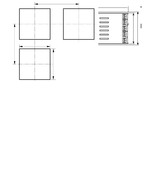
JDimensions
58 |
|
|
53j |
13 |
100 |
j 44.8
48
JPanel cutout
65 mm min
Unit (mm)
60 mm min |
45 +00.6 |
45 +00.6
C• Recommended panel thickness is 1 to 5 mm.
C• Maintain the specified vertical and hori# zontal mounting space between each con# troller.
Controllers must not be closely mounted vertically or horizontally.
2–4
2.2 Installation 

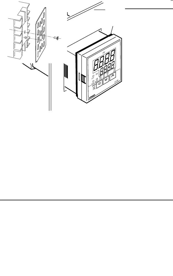
JMounting
(1)Insert the E5CK controller into the mounting hole in the panel at the position shown in the figure above.
(2)Push the adapter along the controller body from the terminals up to the panel, and fasten temporarily.
(3)Tighten the two fixing screws on the adapter. When tightening screws, tighten the two screws alternately keeping the torque to approximately 0.29 to 0.39 N·m, or 3 to 4 kgf·cm.
About the Terminal |
E5CK#AA1#500 controller is provided with a terminal cover (E53#COV07). Fasten |
Cover |
the terminal cover as follows by using the snap pin. |
2–5


 CHAPTER 2 PREPARATIONS
2.3 Wiring Terminals
JTerminal arrangement
AC100-240V |
|
OUT1 |
|
|
||
|
|
|
|
|||
(AC/DC24V ) |
|
|
|
|
||
|
|
|
5 |
11 12 |
10 |
OUT2 |
|
SOURCE |
|
||||
|
|
4 |
|
9 |
||
|
|
|
|
|
||
|
SUB1 |
3 |
|
8 |
|
|
|
2 |
|
7 |
IN |
||
|
|
|
13 14 |
|||
|
|
|
1 |
6 |
|
|
OPTION
JPrecautions when wiring
JWiring
F Power supply
5 11 12 10
49
38
2 7
1 13 14 6
C• Use ducts to separate input leads and power lines in order to protect the controller and its lines from external noise.
C• We recommend using solderless terminals when wiring the controller. C• Tighten the terminal screws using a torque no greater than 0.78 N·m, or 8 kgf·cm max. Take care not to tighten the terminal screws too tightly.
C• Use the following type of solderless terminals for M3.5 screws.
7.2mm max.
7.2mm max.
In the following wiring diagrams, the left side of the terminal Nos. indi# cates the inside of the controller
C• Input power to terminal Nos. 4 and 5. Power specifications are as follows: AC100#240V , 50/60Hz, 15VA
(AC/DC24V , 50/60Hz, 6VA, 3.5W)
About the power blocks
The E5CK has independent power supplies for each of the ter# minal blocks shown on the right. However, note that the power supplies for blocks C (exclude relay output) and D are shared for the following option unit.
C• Option unit : E53-CKB or E53-CKF
AC
511 12 10
49
C 3 8 2 7
1 13 14 6
DB
2–6
|
|
|
|
|
|
|
2.3 Wiring Terminals |
|
|
|
|
|
|
||||
F Input |
|
|
C• Connect the input to terminal Nos. 6 to 8 as follows according to the |
|||||
5 |
|
|
10 |
input type. |
|
|
|
|
11 |
12 |
8 |
8 |
8 |
8 |
|
||
|
|
|
||||||
4 |
|
|
9 |
- |
7 |
- |
- |
|
3 |
|
|
8 |
7 |
7 |
7 |
|
|
|
|
6 |
6 |
V |
mA |
|||
2 |
|
|
7 |
6 |
6 |
|
||
|
|
+ |
|
+ |
+ |
|
||
1 |
13 |
14 6 |
Thermocouple |
Platinum resistance |
Voltage input |
Current input |
||
|
|
|
|
|
thermometer |
|
|
|
|
|
|
|
TC PT |
V |
I |
||
F Control output
5 11 12 10
49
38
2 7
1 13 14 6
C• Match the inputs with the internal jumper settings for each input type. For thermocouple or platinum resistance thermometer inputs, set the inputs to a common position (TC/PT) as the temperature input. For details on jumper connector positions, see page 2#2.
C• Terminal Nos. 11 and 12 are for control output 1 (OUT1). The five out# put types and internal equalizing circuits are available according to out# put unit:
|
+v |
|
+ |
+v |
+ |
|
+ |
|
+ |
||
11 |
|
11 |
|
|
11 |
|
11 |
|
11 |
||
|
|
|
|
|
|||||||
|
|
|
|
L |
|
|
L |
V |
L |
mA |
L |
12 |
GND |
|
GND |
12 |
|
12 |
|
12 |
|||
|
12 |
|
|
||||||||
|
|
|
|||||||||
|
- |
|
|
- |
|
- |
|
- |
|||
Relay |
|
|
|
|
|
|
|||||
|
|
|
NPN |
|
|
PNP |
|
0 to 10V |
4 to 20mA/0 to 20mA |
||
E53-R4R4 |
|
E53-Q4R4 |
E53-Q4HR4 |
E53-V44R4 |
E53-C4R4 |
||||||
|
|
E53-Q4Q4 |
E53-Q4HQ4H |
|
|
E53-C4DR4 |
|||||
C• Terminal Nos. 9 and 10 are for control output 2 (OUT2). The three out# put types and internal equalizing circuits are available according to out# put unit:
+ |
+v |
+ |
10 |
+v |
10 |
L
9GND 9 -
Relay |
NPN |
PNP |
E53-R4R4 /E53-V44R4 |
E53-Q4Q4 |
E53-Q4HQ4H |
E53-Q4R4 /E53-C4R4 |
|
|
E53-Q4HR4/E53-C4DR4 |
|
|
C• The following table shows the specifications for each output type.
Output Type |
Specifications |
|
|
Relay |
250VAC, 3 A |
Voltage (NPN) |
12VDC, 20 mA (with short-circuit protection) |
Voltage (PNP) |
12VDC, 20 mA (with short-circuit protection) |
|
|
0 to 10V |
0 to 10VDC, Permissible load impedance: |
|
1 kΩ min., Resolution: Approx. 2600 |
4 to 20mA |
4 to 20 mA, Permissible load impedance: |
|
500 Ω max., Resolution: Approx. 2600 |
0 to 20mA |
0 to 20 mA, Permissible load impedance: |
|
500 Ω max., Resolution: Approx. 2600 |
|
|
2–7


 CHAPTER 2 PREPARATIONS
F Auxiliary output 1
5 11 12 10
49
38
2 |
|
|
7 |
1 |
13 |
14 |
6 |
C• Terminal Nos. 2 and 3 are for auxiliary output 1 (SUB1).
C• The internal equalizing circuit for auxiliary output 1 is as follows:
3
2
C• Relay specifications are as follows:
SPST#NO, 250VAC, 1A
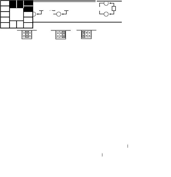
F Option
5 11 12 10
49
38
2 |
|
|
7 |
1 |
13 |
14 |
6 |
C• Terminal Nos. 1, 13 and 14 are valid only when the option unit is set in the controller.
C• The following four connections are possible depending on the type of option unit.
RS-232C |
RS-485 |
Event input |
Transfer output |
E53-CK01 |
E53-CK03 |
E53-CKB |
E53-CKF |
C• For details on RS#232C and RS#485 communications functions, see Chapter 6 Using the Communications Function.
C• Use event inputs under the following conditions
Contact input |
ON: 1 kΩ max., OFF: 100 kΩ min. |
|
|
No-contact input |
ON: residual voltage 1.5V max., OFF: leakage current 0.1mA |
|
max. |
|
|
Polarities during no#contact input are as follows:
+
13
14
–
1
C• Transfer output specifications are as follows:
4 to 20 mA, Load 500 Ω max., Resolution approx. 2600
2–8

CHAPTER 3 BASIC OPERATION 

CHAPTER3
BASIC OPERATION
This chapter describes an actual example for understanding the basic operation of the E5CK.
3.1 Control Example . . . . . . . . . . . . . . . . . . . . . . . 3-2
3.2 Setting Input Specifications . . . . . . . . . . . . . 3-3
Input type . . . . . . . . . . . . . . . . . . . . . . . . . . . . . 3-3
Scaling . . . . . . . . . . . . . . . . . . . . . . . . . . . . . . . . 3-3
3.3 Setting Output Specifications . . . . . . . . . . . 3-5
Output assignments . . . . . . . . . . . . . . . . . . . . 3-5
Direct/reverse operation . . . . . . . . . . . . . . . . 3-5
Control period . . . . . . . . . . . . . . . . . . . . . . . . . 3-6
3.4 Setting Alarm Type . . . . . . . . . . . . . . . . . . . . 3-7 Alarm type . . . . . . . . . . . . . . . . . . . . . . . . . . . . 3-7 Alarm value . . . . . . . . . . . . . . . . . . . . . . . . . . . 3-7 Alarm hysteresis . . . . . . . . . . . . . . . . . . . . . . . 3-8 Close in alarm/open in alarm . . . . . . . . . . . . 3-8
3.5 Protect Mode . . . . . . . . . . . . . . . . . . . . . . . . . . 3-10 Security . . . . . . . . . . . . . . . . . . . . . . . . . . . . . . . 3-10 A/M key protect . . . . . . . . . . . . . . . . . . . . . . . . 3-10 3.6 Starting and Stopping Operation . . . . . . . . 3-11
3.7 Adjusting Control Operation . . . . . . . . . . . . 3-12
Changing the set point . . . . . . . . . . . . . . . . . 3-12
Manual operation . . . . . . . . . . . . . . . . . . . . . . 3-12
Auto#tuning (A.T.) . . . . . . . . . . . . . . . . . . . . . 3-13
3–1


 CHAPTER 3 BASIC OPERATION
3.1 Control Example
This chapter describes the following control example to facilitate under# standing of the basic operation of the E5CK controller.
This description assumes that the controller is operated under the follow# ing conditions.
C• A humidity sensor of output 4 to 20 mA is connected to the controller.
|
|
|
The measuring range of the humidity sensor is set to 10 to 95%. |
||||
|
|
|
C• A humidifier is controlled by pulse output to maintain humidity at a |
||||
|
|
|
constant 60%. |
|
|
||
|
|
|
C• An alarm is output when the humidity exceeds the upper limit value |
||||
|
|
|
(70%) or lower limit value (50%). |
||||
F Setup |
|
C• Output unit: relay/relay type (E53#R4R4) |
|||||
|
|
|
C• Input type jumper connector: •I (current input)" |
||||
|
|
|
|
|
|
|
Humidity sensor |
|
|
|
|
Humidifier |
|
|
|
|
|
|
|
|
OUT1 |
|
Control target |
|
|
|
|
|
|
|
|
AC100-240V |
|
|
|
|
|
|
|
(AC/DC24V |
) |
|
|
|
|
OUT2 |
|
|
|
|
5 |
11 |
12 10 |
||
|
SOURCE |
4 |
|
|
9 |
Alarm 1 |
|
|
|
|
|
|
(deviation upper-and |
||
|
|
|
|
|
|
|
|
|
|
3 |
|
|
8 |
lower-limit) |
|
|
|
2 |
|
|
7 |
4 to 20mA |
|
|
|
1 |
13 |
14 |
6 |
|
|
|
|
|
|
|
|||
E5CK
3–2
 Loading...