


 Loading...
Cat. No. W13E-EN-02
SmartSlice GRT1-Series
GRT1-PNT
PROFINET IO
Communication Unit
OPERATION MANUAL

Notice
OMRON products are manufactured for use by a trained operator and only for the purposes described in this manual.
The following conventions are used to classify and explain the precautions in this manual. Always heed the information provided with them.
!WARNING Indicates information that, if not heeded, could possibly result in serious injury or loss of life.
!Caution Indicates information that, if not heeded, could possibly result in minor or relatively serious injury, damage to the product or faulty operation.
OMRON product references
All OMRON products are capitalized in this manual.
The first letter of the word Unit is also capitalized when it refers to an OMRON product, regardless of whether it appears in the proper name of the product.
Visual aids
The following heading appears in the left column of the manual to help you locate different types of information.
Note Indicates information of particular interest for efficient and convenient operation of the product.
1,2,3... Indicates various lists such as procedures, checklists etc.
Trademarks and copyrights
All product names, company names, logos or other designations mentioned herein are trademarks of their respective owners.
Copyright
Copyright © 2010 OMRON
All rights reserved. No part of this publication may be reproduced, stored in a retrieval system, or transmitted, in any form, or by any means, mechanical, electronic, photocopying, recording, or otherwise, without the prior written permission of OMRON.
No patent liability is assumed with respect to the use of the information contained herein. Moreover, because OMRON is constantly striving to improve its high-quality products, the information contained in this manual is subject to change without notice. Every precaution has been taken in the preparation of this manual. Nevertheless, OMRON assumes no responsibility for errors or omissions. Neither is any liability assumed for damages resulting from the use of the information contained in this publication
iii

iv
TABLE OF CONTENTS
Precautions |
vii |
|
1 |
Intended audience.................................................................................................................................. |
viii |
2 |
General precautions ............................................................................................................................... |
viii |
3 |
Safety precautions.................................................................................................................................. |
viii |
4 |
Operating environment precautions ........................................................................................................ |
ix |
5 |
Application precautions ............................................................................................................................ |
x |
6 Conformance to EC Directives................................................................................................................ |
xi |
|
SECTION 1 |
|
|
Features and specifications |
1 |
|
1-1 Overview of GRT1-series SmartSlice I/O Units........................................................................................ |
2 |
|
1-2 GRT1-PNT PROFINET IO Communication Unit ...................................................................................... |
3 |
|
1-3 GRT1-END-M memory end unit ............................................................................................................... |
9 |
|
1-4 |
GRT1-PNT configuration........................................................................................................................ |
10 |
1-5 |
Basic operating procedure ..................................................................................................................... |
12 |
SECTION 2 |
|
|
Installation and wiring |
15 |
|
2-1 |
GRT1-PNT Unit components ................................................................................................................. |
16 |
2-2 |
GRT1-END-M Unit components............................................................................................................. |
22 |
2-3 Installing the GRT1-PNT Unit................................................................................................................. |
23 |
|
2-4 Wiring the GRT1-PNT Unit..................................................................................................................... |
28 |
|
2-5 Setting up the PROFINET IO network.................................................................................................... |
32 |
|
2-6 Installation of Configuration Software..................................................................................................... |
38 |
|
SECTION 3 |
|
|
Set-up and operation |
41 |
|
3-1 Device name setting and I/O allocation ................................................................................................. |
42 |
|
3-2 |
Unit functions.......................................................................................................................................... |
46 |
3-3 |
GRT1-END-M Unit functions .................................................................................................................. |
52 |
3-4 Set-up the GRT1-PNT Configuration ..................................................................................................... |
54 |
|
3-5 |
Monitoring the GRT1-PNT...................................................................................................................... |
62 |
3-6 |
I/O communication characteristics ......................................................................................................... |
65 |
SECTION 4 |
|
|
Troubleshooting and maintenance |
69 |
|
4-1 |
Overview ................................................................................................................................................ |
70 |
4-2 Troubleshooting using the LED indicators.............................................................................................. |
71 |
|
4-3 |
Other errors ............................................................................................................................................ |
76 |
4-4 |
Maintenance........................................................................................................................................... |
79 |
4-5 |
Replacing the Unit .................................................................................................................................. |
80 |
v

Appendix A |
|
|
PROFINET IO technology |
83 |
|
A-1 |
Introduction to PROFINET ..................................................................................................................... |
83 |
A-2 |
PROFINET Communication................................................................................................................... |
84 |
A-3 |
PROFINET Distributed I/O..................................................................................................................... |
85 |
A-4 |
PROFINET Communication Services .................................................................................................... |
89 |
A-5 |
Alarms.................................................................................................................................................... |
90 |
A-6 |
FDT/DTM Technology............................................................................................................................ |
91 |
Appendix B |
|
|
PROFINET IO alarm messages |
93 |
|
B-1 |
Introduction ............................................................................................................................................ |
93 |
B-2 |
Alarm messages .................................................................................................................................... |
94 |
Appendix C |
|
|
Explicit messages |
95 |
|
C-1 Basic format of explicit messages.......................................................................................................... |
95 |
|
C-2 Explicit messages common to all IO devices......................................................................................... |
97 |
|
C-3 Example of using explicit messages ...................................................................................................... |
98 |
|
Revision history |
105 |
|
vi
Precautions
This chapter provides general precautions for using the GRT1-series modules, Programmable Controllers and related devices.
The information contained in this section is important for the safe and reliable operation of the GRT1PNT PROFINET IO Communication Unit. You must read this section and understand the information contained before attempting to set up or operate a GRT1-PNT PROFINET IO Communication Unit and related systems.
Precautions |
vii |
|
1 |
Intended audience.................................................................................................................................. |
viii |
2 |
General precautions............................................................................................................................... |
viii |
3 |
Safety precautions ................................................................................................................................. |
viii |
4 |
Operating environment precautions ........................................................................................................ |
ix |
5 |
Application precautions ............................................................................................................................ |
x |
6 |
Conformance to EC Directives................................................................................................................ |
xi |
vii

Intended audience |
1 |
1 Intended audience
This manual is intended for the following personnel, who must also have knowledge of electrical systems (an electrical engineer or the equivalent).
•Personnel in charge of installing FA systems.
•Personnel in charge of designing FA systems.
•Personnel in charge of managing FA systems and facilities.
2 General precautions
The user must operate the product according to the performance specifications described in the operation manuals.
Before using the product under conditions which are not described in the manual or applying the product to nuclear control systems, railroad systems, aviation systems, vehicles, combustion systems, medical equipment, amusement machines, safety equipment, and other systems, machines, and equipment that may have a serious influence on lives and property if used improperly, consult your OMRON representative.
Make sure that the ratings and performance characteristics of the product are sufficient for the systems, machines, and equipment, and be sure to provide the systems, machines, and equipment with double safety mechanisms.
This manual provides information for installing and operating using the OMRON GRT1-PNT PROFINET IO Communication Unit. Be sure to read this manual before attempting to use the Unit and keep this manual close at hand for reference during operation.
!WARNING It is extremely important that the Unit is used for the specified purpose and under the specified conditions, especially in applications that can directly or indirectly affect human life. You must consult with your OMRON representative before using the Unit in a system in the above mentioned applications.
3 Safety precautions
!WARNING Provide safety measures in external circuits (i.e., not in the Programmable Controller), including the following items, to ensure safety in the system if an abnormality occurs due to malfunction of the PLC or another (external) factor affecting the operation of the PLC. Not doing so may result in serious accidents.
•Emergency stop circuits, interlock circuits, limit circuits and similar safety measures must be provided in external control circuits.
•The PLC will stop operation when its self-diagnosis function detects any error or when a severe failure alarm (FALS) instruction is executed. As a countermeasure for such errors, external safety measures must be provided to ensure safety in the system.
•The PLC outputs may remain ON or OFF due to deposits on or burning of the output relays, or destruction of the output transistors. As a countermeasure for such problems, external safety measures must be provided to ensure safety in the system.
•When the 24 VDC output (service power supply to the PLC) is overloaded or shortcircuited, the voltage may drop and result in the outputs being turned OFF. As a countermeasure for such problems, external safety measures must be provided to ensure safety in the system.
•SmartSlice I/O Terminals will continue operating even if one or more I/O Units is removed from or falls out of the SmartSlice I/O Terminal, i.e., the other I/O Units will continue control operations, including outputs. As a countermeasure for such problems, external safety measures must be provided to ensure safety in the system.
viii

Operating environment precautions |
4 |
!WARNING The CPU Unit refreshes I/O even when the program is stopped (i.e., even in PROGRAM mode). Confirm safety thoroughly in advance before changing the status of any part of memory allocated to Output Units, Special I/O Units, or CPU Bus Units. Any changes to the data allocated to any Unit may result in unexpected operation of the loads connected to the Unit. Any of the following operations may result in changes to memory status.
•Transferring I/O memory data to the CPU Unit from a Programming Device.
•Changing present values in memory from a Programming Device.
•Force-setting/force-resetting bits from a Programming Device.
•Transferring I/O memory files from a Memory Card or EM file memory to the CPU Unit.
•Transferring I/O memory from a host computer or from another PLC on a network.
!WARNING Never attempt to disassemble any Units or touch the terminal block while power is being supplied. Doing so may result in serious electrical shock or electrocution.
4 Operating environment precautions
!Caution Do not operate the control system in the following locations:
•Locations subject to direct sunlight.
•Locations subject to temperatures or humidities outside the range specified in the specifications.
•Locations subject to condensation as the result of severe changes in temperature.
•Locations subject to corrosive or flammable gases.
•Locations subject to dust (especially iron dust) or salts.
•Locations subject to exposure to water, oil, or chemicals.
•Locations subject to shock or vibration.
Provide proper shielding when installing the Unit in the following locations:
•Locations subject to static electricity or other forms of electric noise.
•Locations subject to strong electromagnetic fields.
•Locations subject to possible exposure to radioactivity.
•Locations close to power supplies.
!Caution The operating environment of the Unit can have a large effect on the longevity and reliability of the system. Unsuitable operating environments can lead to malfunction, failure and other unforeseeable problems with the system. Ensure that the operating environment is within the specified conditions at installation and remains within the specified conditions during the life of the system. Follow all installation instructions and precautions provided in the operation manuals.
ix

Application precautions |
5 |
5 Application precautions
Observe the following precautions when using the GRT1-PNT PROFINET IO Communication Unit.
!WARNING Failure to abide by the following precautions could lead to faulty operation of the Unit or the system. Always heed these precautions:
•Install double safety mechanisms to ensure safety against incorrect signals that may be produced by broken signal lines or momentary power interruptions.
•When adding a new device to the network, make sure that the baud rate is the same as other stations.
•When adding a new SmartSlice I/O Unit to the Communication Unit, make sure that the CJ1W-PNT21 PROFINET IO Communication Unit is powered down, to prevent unexpected results when starting up the new station.
•Use specified communication cables.
•Do not extend connection distances beyond the ranges given in the specifications.
•Always turn OFF the power supply to the personal computer, Slaves, and Communication Units before attempting any of the following:
•Mounting or dismounting the CJ1W-PNT21 PROFINET IO Communication Unit, Power Supply Units, I/O Units, CPU Units, or any other Units.
•Assembling a Unit.
•Setting DIP-switches or rotary switches.
•Connecting or wiring the cables.
•Connecting or disconnecting connectors.
•Be sure that all the mounting screws, terminal screws, Unit mounting screws, and cable connector screws are tightened to the torque specified in the relevant manuals. Incorrect tightening torque may result in malfunction.
•Always use the power supply voltage specified in this manual.
•Double-check all the wiring and connection of terminal blocks and connectors before mounting the Units.
•Take appropriate measures to prevent foreign objects from entering the unit when mounting or wiring it. Failure to do so, may result in unit damage, electric shock or fire.
•Use crimp terminals for wiring. Do not connect bare stranded wires directly to terminals.
•Observe the following precautions when wiring the communication cable.
•Separate the communication cables from the power lines or high-tension lines.
•Do not bend the communication cables.
•Do not pull on the communication cables.
•Do not place heavy objects on top of the communication cables.
•Be sure to wire communication cable inside ducts.
•Use appropriate communication cables.
•Take appropriate measures to ensure that the specified power with the rated voltage and frequency is supplied in places where the power supply is unstable. An incorrect supply power may result in malfunction.
•Install external breakers and take other safety measures against short-circuits in external wiring. Insufficient safety measures against short-circuits may result in burning.
•Double-check all the wiring and switch settings before turning ON the power supply.
•When transporting or storing the product, cover the PCB’s with electrically conductive materials to prevent LSI’s and IC’s from being damaged by static electricity, and also keep the product within the specified storage temperature range.
•When transporting the Unit, use special packing boxes and protect it from being exposed to excessive vibration or impacts during transportation.
•Do not attempt to disassemble, repair, or modify any Units.
•Do not remove the network cable during operation. Removing the network cable result in communication failures.
!WARNING Failure to abide by the following precautions could lead to faulty operation of the Unit or the system. Always heed these precautions:
x
Conformance to EC Directives |
6 |
•Always connect to a class-3 ground (100 Ω or less) when installing the Units.
•Fail-safe measures must be taken by the customer to ensure safety in the event of incorrect, missing, or abnormal signals caused by broken signal lines, momentary power interruptions, or other causes.Not doing so may result in serious accidents.
6 Conformance to EC Directives
6-1 Applicable directives
• EMC (ElectroMagnetic Compatibility) Directives
• Low-voltage directive
6-2 Concepts
OMRON units complying with EC Directives also conform to related product standards making them easier to incorporate in other units or machines. The actual products have been checked for conformity to product standards. Whether the products conform to the standards in the system used by the customer, however, must be checked by the customer.
Product related performance of OMRON units complying with EC Directives will vary depending on the configuration, wiring, and other conditions of the equipment or control panel in which OMRON devices are installed. The customer must, therefore, perform final checks to confirm that units and the overall system conforms to product standards.
A Declaration of Conformity for the GRT1-PNT PROFINET IO Communication Unit can be requested at your nearest OMRON representative.
6-3 Conformance to EC Directives
PROFINET IO units should be installed as follows, for the complete configuration to meet the EC directives:
1The units are designed for installation inside control panels. All units must be installed within control panels.
2Use reinforced insulation or double insulation for the DC power supplies used for the communication power supply, internal circuit power supply, and the I/O power supplies. Ensure that stable outputs can be provided even if a 10 ms interruption occurs at the input.
3The GRT1-PNT PROFINET IO Communication Unit meets the generic emission standard. However as EMC performance can vary in the final installation, additional measures may be required to meet the standards. It should therefore be verified that the overall machine or device also meets the relevant standards. You must therefore confirm that EC directives are met for the overall machine or device, particularly for the radiated emission requirement (10 m).
xi

Conformance to EC Directives |
6 |
xii
SECTION 1
Features and specifications
This section provides an introductory overview of the GRT1 series SmartSlice I/O Units and the GRT1-PNT PROFINET IO Communication Unit, its functions and how to set up and configure it for a PROFINET network.
SECTION 1 |
|
|
Features and specifications |
1 |
|
1-1 Overview of GRT1-series SmartSlice I/O Units ....................................................................................... |
2 |
|
1-2 |
GRT1-PNT PROFINET IO Communication Unit...................................................................................... |
3 |
1-3 |
GRT1-END-M memory end unit............................................................................................................... |
9 |
1-4 |
GRT1-PNT configuration........................................................................................................................ |
10 |
1-5 |
Basic operating procedure ..................................................................................................................... |
12 |
1
Overview of GRT1-series SmartSlice I/O Units |
Section 1-1 |
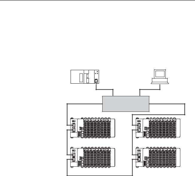
1-1 Overview of GRT1-series SmartSlice I/O Units
The GRT1-Series SmartSlice I/O Units are building-block style I/O Devices, which can be expanded in small I/O increments. This provides the possibility to configure I/O systems which exactly match the various customer applications. SmartSlice I/O Units communicate with the PROFINET IO Controller Unit by remote I/O communication through a PROFINET IO Communication Unit. The figure below shows a typical I/O configuration.
Switch / MRP Manager
Figure 1.1: GRT1-PNTs connected to an IO Controller through Profinet
GRT1-series SmartSlice I/O |
The GRT1-Series of SmartSlice I/O Units, Communication Units and |
|
and PROFINET IO Units |
PROFINET IO Units is constantly being expanded with new Units. Refer to the |
|
|
following manuals. |
|
|
|
|
|
Name |
Manual Reference |
|
|
|
|
GRT1 Series SmartSlice I/O Units Operation Manual |
W455 |
|
|
|
|
GRT1-DRT DeviceNet Communication Unit Operation Manual |
W454 |
|
|
|
|
GRT1-PRT PROFIBUS Communication Unit Operation Manual |
W04E |
|
|
|
|
GRT1-CRT CompoNet Communication Unit Operation Manual |
W476 |
|
|
|
|
SYSMAC CJ-Series CJ1W-PNT21 PROFINET IO Controller |
W12E |
|
Unit Operation Manual |
|
|
|
|
2

GRT1-PNT PROFINET IO Communication Unit Section 1-2
1-2 |
GRT1-PNT PROFINET IO Communication Unit |
|
1-2-1 |
Features |
The GRT1-PNT PROFINET IO Communication Unit for SmartSlice I/O |
|
|
|
|
|
controls data exchange between the PROFINET IO Controller and SmartSlice |
|
|
I/O Units over the PROFINET IO network as an IO Device. For an overview of |
|
|
the PROFINET IO technology refer to Appendix A PROFINET IO technology. |
I/O Data Exchange |
Cyclic I/O data exchange is used to exchange I/O data between the |
|
|
|
PROFINET IO Controller and SmartSlice I/O Units through the PROFINET IO |
|
|
Communication Unit. In addition to I/O data, status information in the |
|
|
PROFINET IO Communication Unit can be accessed from the PROFINET IO |
|
|
Controller Unit. |
FINS/UDP Interface |
The PROFINET IO Communication Unit is provided with a FINS/UDP |
|
|
|
Interface. This enables not only the PROFINET IO Controller to access the |
|
|
SmartSlice I/O Units using OMRON FINS messaging, but any device which |
|
|
supports a UDP interface (such as a Personal Computer using CX-Server |
|
|
Lite). This allows for configuration and monitoring of the SmartSlice I/O Units |
|
|
from remote stations. |
Simplified Start-up |
The PROFINET IO Communication Unit can be set up easily, just by wiring the |
|
|
|
Unit, configuring the PROFINET IO network using CX-ConfiguratorFDT and |
|
|
making simple DIP switch settings. The Unit's configuration is read |
|
|
automatically when the power is turned ON and I/O is also automatically |
|
|
allocated in the SmartSlice I/O Units. |
Device Name Store In |
The separately available GRT1-END-M Memory End Unit facilitates easy |
|
GRT1-END-M Memory End |
replacement of the PROFINET IO Communication Unit. It optionally replaces |
|
Unit |
|
the standard GRT1-END End Unit. No re-configuration using CX- |
|
|
ConfiguratorFDT is required in case of replacement of the Communication |
|
|
Unit. The PROFINET IO Device name, used for identification of the |
|
|
Communication Unit on the PROFINET IO network, is backed up and restored |
|
|
to and from the GRT1-END-M Memory End Unit. |
Easy PROFINET IO |
The PROFINET IO Communication Unit is equipped with two ethernet ports. |
|
Network Layout |
The built-in ethernet switch functionality allows for easy line configuration of |
|
|
|
the network, as additional external ethernet switches may not be necessary. |
MRP Ring Redundancy |
To avoid a single network failure causing communication failure within a large |
|
|
|
part of the network, the units can be set up in a ring topology. MRP Ring |
|
|
Redundancy as specified in the PROFINET standards ensures |
|
|
communication to all remaining devices through the redundant path. |
Facilitating IO Controller |
To ensure a safe implementation of the application, the PROFINET IO |
|
Redundancy |
Communication Unit and the PROFINET IO Controller offer the possibility of |
|
|
|
PLC system redundancy. Two IO Controllers (active and standby) are present |
|
|
in a network connected to all I/O Devices. This feature ensures a fast change |
|
|
from active to standby PLC / IO Controller in case of malfunction. |
Simplified I/O Wiring |
All SmartSlice I/O Units that connect to a PROFINET IO Communication Unit |
|
|
|
are equipped with screw-less clamp terminal blocks. Wiring to external I/O is |
|
|
accomplished just by inserting the wire into the terminals, eliminating the need |
|
|
to tighten terminal screws. |
3

GRT1-PNT PROFINET IO Communication Unit |
Section 1-2 |
|
Table Registration |
The configuration of the SmartSlice I/O Units (mounting order and I/O size) |
|
|
connected to a PROFINET IO Communication Unit can be registered in a |
|
|
table simply by setting a DIP switch. Once the table has been registered, the |
|
|
actual configuration is compared to the registered configuration each time that |
|
|
the power is turned ON. If the configuration does not match, a status flag is |
|
|
turned ON in the PROFINET IO Controller to indicate the error. |
|
On-line Replacement of I/O |
The SmartSlice I/O Unit's circuit section can be removed, so it is not |
|
Units |
necessary to turn OFF the Communication Unit’s power to replace a Unit. |
|
|
Communication can be maintained in the remaining (connected) Units. |
|
Parameter Backup and |
Before replacing a SmartSlice I/O Unit for maintenance, the parameter data |
|
Restores |
set in all SmartSlice I/O Units can be backed up in the PROFINET IO |
|
|
Communication Unit by toggling a DIP switch. Another DIP selects the mode |
|
to automatically write the back-up parameter data to the replacement SmartSlice I/O Unit.
1-2-2 System configuration
|
The PROFINET IO Communication Unit connects to the IO Controller by an |
||||
|
Ethernet network cable and it connects to the SmartSlice I/O Units by directly |
||||
|
coupling the Units together. |
|
|
||
I/O Data Exchange |
The I/O Unit data in the PROFINET IO Communication Unit is shared with the |
||||
|
IO Controller's Input and Output Areas through the PROFINET IO network. |
||||
|
The I/O Units' data is collected in the PROFINET IO Communication Unit and |
||||
|
exchanged with the IO Controller cyclically. |
||||
Messaging Services |
The GRT1-PNT PROFINET IO Communication Unit also supports messaging |
||||
|
services using FINS/UDP, allowing the user to send acyclic message |
||||
|
commands addressed to the GRT1-PNT Unit or individual SmartSlice I/O |
||||
|
Units. This can be sent from the PLC or for instance the Personal Computer. |
||||
End Unit for PROFINET IO |
Always install an End Unit on the |
last I/O Unit in the system. For the |
|||
|
PROFINET IO Communication Unit there are two options: |
||||
|
|
|
|
|
|
|
Type |
I/O points |
Model number |
|
Description |
|
|
|
|
|
|
|
End Unit |
-- |
GRT1-END |
|
End Unit to be mounted to the end of the |
|
|
|
|
|
SmartSlice I/O Terminal. |
|
|
|
|
|
|
|
Memory |
2 input bits |
GRT1-END-M |
|
End Unit to be mounted to the end of the |
|
End Unit |
|
|
|
SmartSlice I/O Terminal. |
|
|
|
|
|
The unit has a backup of the IO Device |
|
|
|
|
|
Name of the Communication Unit. |
|
|
|
|
|
|
|
In case of replacement of the PROFINET IO Communication Unit, the |
||||
|
PROFINET IO Device Name will be restored from the GRT1-END-M Unit to |
||||
|
the new Communication Unit. In case of the standard GRT1-END, additional |
||||
|
configuration download using CX-ConfiguratorFDT is required after |
||||
|
replacement. |
|
|
|
|
Note |
1 Unlike the standard End Unit, the Memory End Unit will count as one SmartSlice I/O |
||||
|
Unit. Up to 63 SmartSlice I/O Units can be connected to one PROFINET IO Com- |
||||
|
munication Unit when the GRT1-END-M is used. |
||||
2The GRT1-END-M Memory End Unit functionality only applies to the PROFINET IO Communication Unit. Although the Memory End Unit has the basic End Unit funtionality, the Unit is not aimed to be used together with other Communication Units.
4

GRT1-PNT PROFINET IO Communication Unit |
|
|
|
Section 1-2 |
|||||
|
|
|
|
|
|
|
|
|
|
|
|
|
|
|
|
|
|
|
|
|
|
|
|
|
|
|
|
|
|
|
|
|
|
|
|
|
|
|
|
|
|
|
|
|
|
|
|
|
|
|
|
|
|
|
|
|
|
|
|
1 |
|
|
|
|
|
|
|
2 |
|
|
|
|
|||||
|
|
|
|
|
|
|
|
|
Switch
Figure 1.2: A single GRT1-PNT connects to multiple I/O blocks via Turnback units.
1Remote I/O data is collected from the connected SmartSlice I/O Units and exchanged with the IO Controller Unit
2Acyclic messages are used to monitor operation and write parameters to the SmartSlice I/O Units.
5

GRT1-PNT PROFINET IO Communication Unit Section 1-2
1-2-3 |
Specifications |
|
|
|
Functional specifications |
|
|
||
|
|
|
|
|
Item |
|
|
Specification |
|
|
|
|
|
|
Installation |
|
Unit type |
SmartSlice GRT1 series |
|
|
|
|
|
|
|
|
Model |
GRT1-PNT |
|
|
|
|
|
|
|
|
Mounting position |
DIN Rail mounted |
|
|
|
|
|
|
|
|
Power supply |
24 VDC + 10 % / − 15 % (20.4 VDC to 26.4 VDC) |
|
|
|
Current consumption |
140 mA (max), 120 mA typical at 24 VDC |
|
|
|
Dimensions (WxHxD) |
58 x 80 x 70 mm |
|
|
|
|
|
|
|
|
Weight |
120 g (typical) |
|
|
|
|
||
Environment |
Ambient operating temperature |
−10 °C to +55 °C (no icing or condensation) |
||
|
|
|
|
|
|
|
Ambient operating humidity |
25 % to 85 % Relative Humidity |
|
|
|
|
|
|
|
|
Storage temperature |
−40 °C to +70 °C (no icing or condensation) |
|
|
|
|
|
|
|
|
Vibration resistance |
150 m/s2 |
|
|
|
Dielectric strength |
500 VAC (between isolated circuits) |
|
|
|
|
|
|
|
|
Conformance to EMC and |
EN 61131-2:2003 |
|
|
|
Electrical safety standards |
|
|
|
|
|
|
|
Front case |
|
DIP-switches |
4 DIP switches on the front of the unit: |
|
|
|
|
• Switch 1: Create / Enable registration table |
|
|
|
|
• Switch 2: Not used |
|
|
|
|
• Switch 3: Automatic restore |
|
|
|
|
• Switch 4: Backup Trigger |
|
|
|
|
|
|
|
|
Indicators |
6 LEDs; |
|
|
|
|
Unit status: |
|
|
|
|
• |
RUN (green LED), |
|
|
|
• |
ERR (red LED), |
|
|
|
• UNIT PWR (green LED). |
|
|
|
|
SmartSlice I/O Unit status: |
|
|
|
|
• |
TS (red/green LED), |
|
|
|
• I/O PWR (green LED). |
|
|
|
|
PROFINET IO status: |
|
|
|
|
• BF (red LED). |
|
|
|
|
|
|
|
|
PROFINET IO Connector |
2 x RJ45 8-pin Modular Connector |
|
|
|
|
(conforming to ISO 8877) |
|
|
|
|
|
|
|
|
Power |
Screwless push-in connectors |
|
|
|
|
Unit power and I/O power are separated. |
|
|
|
|
|
|
|
|
Field Ground connector |
Screwless push-in connector |
|
|
|
|
|
|
6

GRT1-PNT PROFINET IO Communication Unit |
Section 1-2 |
|||
|
|
|
|
|
Item |
|
|
Specification |
|
|
|
|
|
|
SmartSlice I/O System |
Number of connectable SmartSlice |
64 units max. (including GRT1-END-M Memory Unit) |
||
|
I/O Units |
Connected directly to the GRT1-PNT or via turnback |
||
|
|
|
extension units. |
|
|
|
|
|
|
|
Turnback cable |
Length 1 m, up to 2 cables can be connected. |
||
|
|
|
|
|
|
SmartSlice I/O Unit connections |
Building-block style configuration (Units connect with Turn- |
||
|
|
|
back cables) |
|
|
|
|
|
|
|
Base block power supply |
Voltage: 24 VDC |
||
|
|
|
Current: 4 A max |
|
|
|
|
|
|
|
Event messaging |
Supported |
|
|
|
|
|
|
|
Protocol specifications |
|
|
||
|
|
|
|
|
Item |
|
|
|
Specification |
|
|
|
|
|
PROFINET interface |
|
Protocol |
|
PROFINET IO |
|
|
|
|
|
|
|
PROFINET unit type |
|
PROFINET IO Device |
|
|
|
|
|
|
|
Isochronous mode |
|
No |
|
|
|
|
|
|
|
Alarms |
|
Yes |
|
|
|
|
|
|
|
Minimum Update Rate |
|
8 ms |
|
|
|
|
|
Transfer specifications |
|
Bitrate |
|
100 Mbps (100Base-TX) |
|
|
|
|
|
|
|
Automatic detection of transmission speed |
Yes |
|
|
|
|
|
|
PROFINET IO cable |
|
Type |
|
LAN balanced of category 5 or higher, |
|
|
|
|
according to ISO/IEC 11801 Edition 2.0 |
|
|
|
|
|
|
|
Core cross section |
|
AWG 22 |
|
|
|
|
|
|
|
Maximum number of connector/socket pairs |
6 |
|
|
|
|
|
|
|
|
Max transmission distance |
|
100 m (distance between nodes) |
|
|
|
|
|
PROFINET redundancy |
|
Protocol |
|
Media Redundancy Protocol (MRP) client |
|
|
|
|
|
Configuration |
|
GSD file |
|
GSDML-V2.1-OMRON-GRT1-PNT- |
|
|
|
|
20081205.xml |
|
|
|
|
|
|
|
DTM |
|
Included in CX-ConfiguratorFDT |
|
|
|
|
|
FINS service |
|
FINS/UDP |
|
Supported |
|
|
|
|
|
7
GRT1-PNT PROFINET IO Communication Unit |
Section 1-2 |
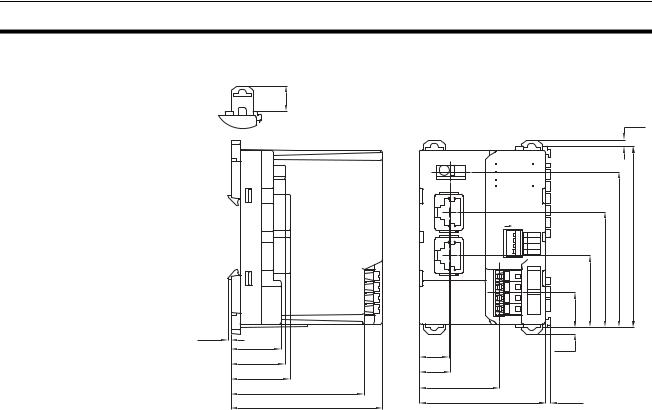
External dimensions |
|
11.75 |
|
|
2.85 |
|
|
OMRON GRT1-PNT |
|
|
|
|
|
|
RUNUNIT PWR |
|
|
|
|
|
|
ERR |
|
|
|
|
|
|
BF |
|
|
|
|
|
|
FG |
I/O PWR |
|
|
|
|
|
TS |
|
|
|
|
|
LNK1 |
PORT1 |
|
|
|
|
|
LNK2 |
PORT2 |
ON |
53.2 |
71.7 |
83.5 |
|
+V |
|||||
|
|
|
1 REGS |
|
|
|
|
|
|
2 NC |
|
|
|
|
|
|
3 ADR |
|
|
|
|
|
|
4 BACK |
|
|
|
|
|
|
UNIT |
|
|
|
|
|
|
-V |
33.2 |
|
|
|
|
|
+V |
|
|
|
|
|
|
I/O |
16.3 |
|
|
|
|
|
DC24V |
|
|
|
|
|
|
-V |
|
|
|
|
|
|
INPUT |
|
|
|
1.5 |
|
|
|
|
|
|
23.1 |
13.5 |
|
2.85 |
|
|
|
24.8 |
|
|
|
|
||
|
14.3 |
|
|
|
|
|
27.1 |
|
|
|
|
|
|
|
36.7 |
|
|
|
|
|
|
61.2 |
|
|
|
|
|
|
58 |
|
2.4 |
|
|
|
|
69.7 |
|
|
|
||
|
|
|
|
|
|
|
Figure 1.2.3: GRT1-PNT PROFINET IO Communication Unit external dimensions
8
GRT1-END-M memory end unit Section 1-3
1-3 |
GRT1-END-M memory end unit |
||||||||||||||
Functional specifications |
|
|
|
|
|
|
|
|
|
|
|
|
|
|
|
|
|
|
|
|
|
|
|
|
|
|
|
|
|
|
|
Item |
|
|
|
Specification |
|||||||||||
|
|
|
|
|
|
|
|
|
|
|
|
|
|
|
|
Installation |
|
Unit type |
SmartSlice GRT1 series |
||||||||||||
|
|
|
|
|
|
|
|
|
|
|
|
|
|
|
|
|
|
Model |
GRT1-END-M |
||||||||||||
|
|
|
|
|
|
|
|
|
|
|
|
|
|
|
|
|
|
Mounting position |
DIN Rail mounted |
||||||||||||
|
|
|
|
|
|
|
|
|
|
|
|
|
|
|
|
|
|
Current consumption |
30 mA (max), 24 mA typical at 24 VDC |
||||||||||||
|
|
Dimensions (WxHxD) |
19.5 x 83.5 x 55.7 mm |
||||||||||||
|
|
|
|
|
|
|
|
|
|
|
|
|
|
|
|
|
|
Weight |
60 g (typical) |
||||||||||||
|
|
|
|
|
|
|
|
|
|
|
|
|
|
|
|
Environment |
Ambient operating temperature |
−10 °C to +55 °C (no icing or condensation) |
|||||||||||||
|
|
|
|
|
|
|
|
|
|
|
|
|
|
|
|
|
|
Ambient operating humidity |
25 % to 85 % relative humidity |
||||||||||||
|
|
|
|
|
|
|
|
|
|
|
|
|
|
|
|
|
|
Storage temperature |
−25 °C to +65 °C (no icing or condensation) |
||||||||||||
|
|
|
|
|
|
|
|
|
|
|
|
|
|
|
|
|
|
Noise immunity |
Conforms to IEC61000-4-4, 2.0 kV |
||||||||||||
|
|
|
|
|
|
|
|
|
|
|
|
|
|
|
|
|
|
Shock resistance |
150 m/s2 |
||||||||||||
|
|
Dielectric strength |
500 VAC |
||||||||||||
|
|
Enclosure rating |
IP20 |
||||||||||||
|
|
|
|
|
|
|
|
|
|
|
|
|
|
|
|
Front case |
|
Indicators |
TS (Two-colour LED): |
||||||||||||
|
|
|
|
indicates the unit’s operating status. |
|||||||||||
|
|
|
|
|
|
|
|
|
|
|
|
|
|
|
|
External dimensions |
|
|
|
|
|
|
|
|
|
|
|
|
|
|
|
|
|
|
|
|
|
|
|
|
|
|
|
|
|
||
|
|
|
|
|
|
|
|
|
|
11.75 |
|
||||
|
|
|
|
|
|
|
|
|
|
|
|||||
|
|
|
|
|
|
|
|
|
|
|
|||||
|
|
|
|
|
|
|
|
|
|
|
|
|
|
|
|
|
|
|
|
|
|
|
|
|
|
|
|
|
|
|
|
|
|
|
|
2.85 |
|
||||||||||
|
|
|
|
|
|
|
|
|
|
|
|
|
|
|
|
|
|
|
|
|
|
|
|
|
|
|
|
|
|
|
|
|
|
|
|
|
|
|
|
|
|
|
|
|
|
|
|
|
|
|
|
|
END-M |
||||||||||
|
|
|
|
|
|||||||||||
|
|
|
|
|
TS |
||||||||||
83.5
|
|
|
|
|
|
|
|
|
|
|
|
|
|
|
|
|
|
|
|
|
|
|
|
|
|
|
|
|
|
|
|
|
|
|
|
|
|
|
|
|
|
|
|
|
|
|
|
|
|
|
|
|
|
|
|
|
|
|
|
|
|
|
|
|
|
|
|
|
|
|
|
|
|
|
|
|
|
|
|
|
|
|
|
|
|
|
|
|
|
|
|
|
|
|
|
|
|
|
|
|
|
55.7 |
|
|
|
|
1.5 |
|
|
|
|
|
|
|
|
2.85 |
|
|
|
|
|
|
|
|
|
|
|
|
|
||||||
Figure 1.3: GRT1-END-M memory end unit external dimensions
9

GRT1-PNT configuration Section 1-4
1-4 |
GRT1-PNT configuration |
||
PROFINET IO |
The PROFINET IO Controller Unit requires a configuration before it can |
||
Configuration Means |
exchange I/O data with any of its IO Devices. For this configuration information |
||
|
|
on the IO device must be available. OMRON provides two means to facilitate |
|
|
|
IO Controller Unit configuration. |
|
|
|
• |
A GRT1-PNT DTM |
|
|
• A GRT1-PNT GSD file |
|
GRT1-PNT Configuration |
The GRT1-PNT DTM is an executable component, provided by OMRON, |
||
DTM |
|
which requires an FDT Container program like OMRON's CX- |
|
|
|
ConfiguratorFDT (see also Appendix A PROFINET IO technology, FDT/DTM |
|
|
|
Technology). The DTM runs inside this FDT Container and provides its own |
|
|
|
User Interface. It can access GRT1-PNT and SmartSlice I/O Unit data using |
|
|
|
FINS/UDP and present that to the user. It can also save the settings, using the |
|
|
|
features of the FDT Container program. The GRT1-PNT DTM provides the |
|
|
|
user with the following features. |
|
|
|
• |
PROFINET I/O Configuration |
|
|
• Configuration of individual SmartSlice I/O Units |
|
|
|
• Monitoring of the SmartSlice I/O System |
|
GRT1-PNT I/O |
The I/O Configuration User Interface allows the user to define the |
||
Configuration |
configuration of SmartSlice I/O Units attached to the PROFINET IO |
||
|
|
Communication Unit. It also allows the user to make parameter settings for |
|
|
|
individual SmartSlice I/O Units. |
|
|
|
The I/O Configuration is used by the PROFINET IO Controller Unit when |
|
|
|
mapping the I/O data of individual SmartSlice I/O Units onto the PLC memory |
|
|
|
areas. It is also sent by the PROFINET IO Controller Unit to the GRT1-PNT for |
|
|
|
verification when establishing communication. The I/O Configuration sent by |
|
|
|
the PROFINET IO Controller Unit must match the physical configuration |
|
|
|
attached to the GRT1-PNT PROFINET IO Communication Unit, in order to |
|
|
|
proceed with I/O data exchange. |
|
Monitoring the SmartSlice |
The Monitoring User Interfaces allows the user to read information from |
||
I/O System |
individual SmartSlice I/O Units. It also provides a means to read the Error Log |
||
|
|
of the GRT1-PNT PROFINET IO Communication Unit. |
|
Configuration via GSD File |
The GSD file concept is other way of configuration. The GSD file for the |
||
|
|
GRT1-PNT is an XML-based file, which contains all options required to |
|
|
|
configure a PROFINET IO Controller Unit. The file can be loaded by the |
|
|
|
configuration software of the IO Controller Units, which will then present the |
|
|
|
information to the user to allow the appropriate selections to be made. |
|
|
|
The drawback of the GSD file is that - unlike the GRT1-PNT DTM - it only |
|
|
|
provides setting options for configuring the PROFINET IO. The GSD file does |
|
|
|
not provide the means to access data of the SmartSlice I/O Units directly. |
|
Third-Party IO Controller |
The GSD file for GRT1-PNT can be used to configure most third-party I/O |
||
Units |
|
Controller Units. The GRT1-PNT GSD file contains all the necessary |
|
|
|
parameters to allow the user to configure the IO Controller Unit for I/O data |
|
|
|
exchange. |
|
10

GRT1-PNT configuration |
Section 1-4 |
|
Note |
1 The GRT1-PNT DTM can also be used in third-party configuration software pro- |
|
|
vided that this software supports the FDT/DTM concept. |
|
|
2 With the CX-ConfiguratorFDT FDT Container OMRON also provides a Generic IO |
|
|
Device DTM, an FDT/DTM interface between the FDT Container program and GSD |
|
|
files. Alternatively, this DTM can be used to set up an IO Controller Unit, using the |
|
|
GRT1-PNT GSD file. This Generic IO Device DTM however, does not provide the |
|
|
means to access data of the SmartSlice I/O Units directly. |
|
Downloading the |
After setting up the configuration, it must be downloaded to the PROFINET IO |
|
configuration |
Controller Unit. The download process depends on the IO Controller Unit |
|
|
used. |
|
11

Basic operating procedure |
Section 1-5 |
1-5 Basic operating procedure
1-5-1 Overview
The following diagram provides an overview of the installation procedures. For experienced installation engineers, this may provide sufficient information. For others, cross-references are made to various sections of this manual where more explicit information is given.
Mount the GRT1-PNT PROFINET IO Unit and the SmartSlice I/O Units including the GRT1-END-M Unit. (See section 2-3 Installing the GRT1-PNT Unit).
T
Wire the GRT1-PNT PROFINET IO Communication Unit
and the SmartSlice I/O Units.
(See section 2-3 Installing the GRT1-PNT Unit).
T
Setup the PROFINET IO network. (See section 2-4 Wiring the GRT1-PNT Unit).
T
Power up the GRT1-PNT and perform initial setup. (See section 3-4 Set-up the GRT1-PNT Configuration).
T
Configure the PROFINET IO Controller Unit. (See section 3-4 Set-up the GRT1-PNT Configuration).
T
PROFINET IO starts communicating, confirmed by the BF LED being not lit. Check status of other LED Indicators.
(See section 3-5 Monitoring the GRT1-PNT).
12

Basic operating procedure Section 1-5
1-5-2 Preparations for use
The following procedure shows the basic steps required before using the PROFINET IO Communication Unit and the SmartSlice I/O Units.
Initial setup procedure |
1 |
Mount the GRT1-PNT Unit and the SmartSlice I/O system on the DIN rail. |
|
|
The maximum number of SmartSlice I/O Units can be 64 (including GRT1- |
|
|
END-M End Unit). |
|
2 |
Wire the SmartSlice I/O Units and the GRT1-PNT Unit's power supply. |
|
3 |
Wire the PROFINET IO network, to connect the Communication Unit to the |
|
|
PROFINET IO Controller Unit. |
|
4 |
Turn ON the power to the Unit and the I/O. |
|
5 |
Turn ON (from OFF to ON) DIP switch 1 on the front of the PROFINET IO |
|
|
Communication Unit. When switch 1 is turned ON, the existing SmartSlice |
|
|
I/O Unit configuration (connection order and I/O size) is registered in the |
|
|
PROFINET IO Communication Unit as a registered table. After the table is |
|
|
registered, leave pin 1 ON to enable the table. |
Note The next time the power is turned ON, the actual SmartSlice I/O Unit configuration at power on is automatically compared to the registered table. Any SmartSlice I/O Units that do not match the registered table (connection order or I/O size) will not participate in I/O communication. I/O communication will start with the other SmartSlice I/O Units.
Configuration procedure Use the following procedure to configure the IO Controller Unit together with the PROFINET IO Communication Unit using CX-ConfiguratorFDT and the IO Controller and IO Device DTMs:
1Turn ON the PLC power supply and the power supplies of the IO Devices on the network.
2In CX-ConfiguratorFDT, create a network and define the parameters and I/O configurations for the PROFINET IO Controller Unit settings and the allocated IO Devices. Choose the update rate for each IO Device.
3Use the PROFINET IO Controller DTM to assign Device Names to the actual IO Devices in the network.
4Download the network configuration to the PROFINET IO Controller Unit. After downloading the configuration, CX-ConfiguratorFDT will restart the PROFINET IO Controller Unit.
5After restarting the PROFINET IO Controller Unit it will automatically start communication when the PLC goes into RUN/MONITOR mode.
13

Basic operating procedure |
Section 1-5 |
14
SECTION 2
Installation and wiring
This section shows the GRT1-series PROFINET IO Communication Unit and identifies its controls and indicators. It contains the procedures for installing and wiring the Communication Unit as well as the GRT1series SmartSlice I/O Units. It also contains the procedures for setting up the PROFINET IO network.
SECTION 2 |
|
|
Installation and wiring |
15 |
|
2-1 |
GRT1-PNT Unit components ................................................................................................................. |
16 |
2-2 |
GRT1-END-M Unit components............................................................................................................. |
22 |
2-3 Installing the GRT1-PNT Unit................................................................................................................. |
23 |
|
2-4 Wiring the GRT1-PNT Unit..................................................................................................................... |
28 |
|
2-5 |
Setting up the PROFINET IO network ................................................................................................... |
32 |
2-6 |
Installation of Configuration Software .................................................................................................... |
38 |
15
GRT1-PNT Unit components |
Section 2-1 |
2-1 GRT1-PNT Unit components
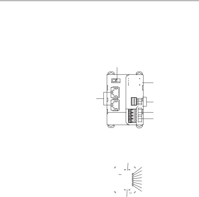
2-1-1 Overview
The illustration below shows the two PROFINET IO Ethernet connectors with Link activity LED indicators (1), the Status LED indicators (3), the Field Ground Terminal (2), the DIP switches (4) and the power supply terminals (5 and 6) on the front side of the PROFINET IO Communication Unit. Each of these components is explained in the following sections.
1
2
OMRON GRT1-PNT
|
FG |
LNK1 |
PORT1 |
LNK2 |
PORT2 |
RUNUNIT PWR
ERR
BF
TS I/O PWR
 ON
ON
1 REGS
2 NC
3 ADR
4 BACK
UNIT
+V
-V
I/O
+V
-V
DC24V
INPUT
3
4
5
6
Figure 2.1: GRT1-PNT overview
2-1-2 Ethernet connectors
The GRT1-PNT contains two Ethernet connector ports. The ports are functionally the same and enable bus line network topology.
9
|
|
|
|
|
|
|
|
|
|
|
|
|
|
|
|
1 |
|
|
|
|
|
|
|
|
|
|
|
|
|
|
|
|
|
|
|
|
|
|
|
|
|
|
|
|
|
|
|
|
|
|
|
2 |
|
|
|
|
|
|
|
|
|
|
|
|
|
|
|
|
|
3 |
|
|
|
|
|
|
|
|
|
|
|
|
|
|
|
|
|
4 |
|
|
|
|
|
|
|
|
|
|
|
|
|
|
|
|
|
|
|
|
|
|
|
|
|
|
|
|
|
|
|
|
|
|
|
5 |
|
|
|
|
|
|
|
|
|
|
|
|
|
|
|
|
|
|
|
|
|
|
|
|
|
|
|
|
|
|
|
|
|
|
|
|
|
|
|
|
|
|
|
|
|
|
|
|
|
|
|
|
|
6 |
|
|
|
|
|
|
|
|
|
|
|
|
|
|
|
|
|
7 |
|
|
|
|
|
|
|
|
|
|
|
|
|
|
|
|
|
8 |
|
|
|
|
|
|
|
|
|
|
|||||||||
|
|
|
|
|
|
|
9 |
|
|
|
|
|
|
|
|
||
|
Figure 2.1.2: GRT1-PNT ethernet connector |
||||||||||||||||
|
|
|
|
|
|
|
|
|
|
|
|
|
|
|
|
|
|
Pin |
Signal |
Abbreviation |
Signal direction |
||||||||||||||
|
|
|
|
|
|
|
|
|
|
|
|
|
|
|
|
|
|
1 |
Transmission data + |
TD+ |
Output |
||||||||||||||
|
|
|
|
|
|
|
|
|
|
|
|
|
|
|
|
|
|
2 |
Transmission data - |
TD- |
Output |
||||||||||||||
|
|
|
|
|
|
|
|
|
|
|
|
|
|
|
|
|
|
3 |
Reception data + |
RD+ |
Input |
||||||||||||||
|
|
|
|
|
|
|
|
|
|
|
|
|
|
|
|
|
|
4 |
Not used |
--- |
|
|
|
|
|
|
|
--- |
|||||||
|
|
|
|
|
|
|
|
|
|
|
|
|
|
|
|
|
|
5 |
Not used |
--- |
|
|
|
|
|
|
|
--- |
|||||||
|
|
|
|
|
|
|
|
|
|
|
|
|
|
|
|
|
|
6 |
Reception data - |
RD- |
Input |
||||||||||||||
|
|
|
|
|
|
|
|
|
|
|
|
|
|
|
|
|
|
7 |
Not used |
--- |
|
|
|
|
|
|
|
--- |
|||||||
|
|
|
|
|
|
|
|
|
|
|
|
|
|
|
|
|
|
8 |
Not used |
--- |
|
|
|
|
|
|
|
--- |
|||||||
|
|
|
|
|
|
|
|
|
|
|
|
|
|
|
|
|
|
9 |
Field Ground |
FG |
--- |
||||||||||||||
|
|
|
|
|
|
|
|
|
|
|
|
|
|
|
|
|
|
16

GRT1-PNT Unit components |
Section 2-1 |
The following standards and specifications apply to the connectors for the
Ethernet twisted-pair cable.
•Electrical specifications: Conforming to IEEE 802.3 standards
•Shielded twisted-pair (STP) cable: minimum category CAT5
•Connector structure: RJ45 8-pin Modular Connector (conforming to ISO 877)
2-1-3 Field Ground Terminal
The GRT1-PNT PROFINET IO Communication Unit provides a Field gGround Terminal at the front side.
|
|
|
|
|
|
|
|
|
OMRON GRT1-PNT |
|
|
|
|
|
|
|
|
|
||
|
|
|
|
|
|
|
|
|
|
FG |
|
|
|
|
|
|
|
|
|
|
|
|
|
|
|
|
|
|
|
|
|
|
|
|
|
|
|
|
|
|
|
|
|
|
|
Figure 2.1.3: GRT1-PNT Field Ground Terminal |
||||||||||||||||
|
|
To help prevent electrical shock and/or if noise is a significant source of errors, |
||||||||||||||||||
|
|
ground the Field Ground Terminal with a ground resistance of less than 100 Ω |
||||||||||||||||||
|
|
using a 14-gauge wire (minimum cross-sectional area of 2 mm2). |
||||||||||||||||||
Recommended Wire |
|
|
|
|
|
|
|
|
|
|
|
|
|
|
|
|
|
|
|
|
|
|
|
|
|
|
|
|
|
|
|
|
|
|
|
|
|
|
|
|
|
|
|
Type |
|
|
|
Gauge |
|
|
|
|
|
|
|
|
|
|||||
|
|
|
|
|
|
|
|
|
|
|
|
|
|
|
|
|
|
|
|
|
|
|
Stranded wire |
|
|
|
20 AWG to 14 AWG |
|
|
|
|
|
|
|
|
|
|||||
|
|
|
|
|
|
|
(0.5 to 2.0 mm2) |
|
|
|
|
|
|
|
|
|
||||
|
|
Pin terminal |
|
|
|
|
|
|
|
|
|
|
|
|
||||||
|
|
|
|
|
|
|
|
|
|
|
|
|
|
|
|
|
|
|
||
|
|
|
|
|
|
|
|
|
|
|
|
|
|
|
|
|
|
|||
Strip Length |
Strip wire between 8 mm and 10 mm of insulation at the ends of the wires |
|||||||||||||||||||
Pin Terminal Length |
(stranded or solid wire) or use pin terminals with a pin (conductor) length of |
|||||||||||||||||||
|
|
8 mm to 10 mm. |
|
|
|
|
|
|
|
|
|
|
|
|
|
|
|
|
|
|
|
|
|
|
|
|
|
|
|
|
|
|
|
|
|
|
|
|
|
|
|
|
|
|
|
|
|
|
|
|
|
|
|
Pin length: 8 to 10 mm |
||||||||
|
|
|
|
Strip 8 to 10 mm. |
||||||||||||||||
|
|
|
|
|
|
|
|
|
|
|
|
|
||||||||
2-1-4 |
LED indicators |
|
|
|
|
|
|
|
|
|
|
|
|
|
|
|
|
|
||
The GRT1-PNT PROFINET IO Communication Unit uses the following LED indicators.
•Six LEDs to indicate status of the Unit and the PROFINET IO network
•Two LEDs at the Ethernet ports to indicate the Link activity of the ports
17

GRT1-PNT Unit components |
Section 2-1 |
RUN |
UNIT PWR |
ERR |
|
BF |
|
TS |
I/O PWR |
|
|
|
|
|
Figure 2.1.4: GRT1-PNT LED indicators |
|
Status indicator |
|
|
|
|||
specification |
|
|
|
|
||
|
|
|
|
|
||
Indicator |
Colour |
Status |
Meaning |
|||
|
|
|
|
|
||
RUN |
Green |
Not lit |
• Start-up test failed, unit not operational. |
|||
Unit status |
|
|
• Fatal error: Operation stopped. |
|||
|
|
|
|
|
||
|
|
|
Lit |
Initialization successful, unit is in normal operation. |
||
|
|
|
|
|
||
ERR |
Red |
Not lit |
Unit is in normal operation. |
|||
Unit error |
|
|
|
|
||
|
Flashing |
A start-up error has occurred. |
||||
|
|
|
||||
|
|
|
|
|
||
|
|
|
Lit |
Fatal error in system execution. |
||
|
|
|
|
|
||
BF |
Red |
Not lit |
• No PROFINET IO communication errors occurred. |
|||
PROFINET IO |
|
|
• I/O data exchange in progress. |
|||
failure |
|
|
|
|
||
|
Flashing |
The configuration settings sent by the PROFINET IO Controller unit are |
||||
|
|
|
||||
|
|
|
|
invalid. No I/O data exchange is possible. |
||
|
|
|
|
|
||
|
|
|
Lit |
No PROFINET IO communication has been detected by the unit. |
||
|
|
|
|
|
|
|
TS |
--- |
Not lit |
• |
No power supplied. |
||
SmartSlice I/O |
|
|
• Communication has not started with SmartSlice I/O Unit. |
|||
system |
|
|
• |
Over current detected. |
||
communication |
|
|
|
|
|
|
|
Green |
Flashing once |
SmartSlice I/O Unit added to the system |
|||
status |
||||||
|
per second |
|
|
|||
|
|
|
|
|
||
|
|
|
|
|
||
|
|
|
Flashing twice |
Backup/Restore function operating: |
||
|
|
|
per second |
• Restoring settings to SmartSlice I/O Unit, backup function operating. |
||
|
|
|
|
• Downloading SmartSlice I/O Unit settings. |
||
|
|
|
|
|
||
|
|
|
Lit |
Communication with SmartSlice I/O Unit established. |
||
|
|
|
|
|
||
|
|
Red |
Flashing |
Non-fatal communication error occurred: |
||
|
|
|
|
• |
Communication time out. |
|
|
|
|
|
• Verification error occurred with registered table. |
||
|
|
|
|
• Different model Unit detected after SmartSlice I/O Unit replacement. |
||
|
|
|
|
|
||
|
|
|
Lit for 2 |
Failure occurred while restoring settings to SmartSlice I/O Unit or |
||
|
|
|
seconds |
downloading SmartSlice I/O Unit settings. |
||
|
|
|
|
|
||
|
|
|
Lit |
Fatal communication error occurred. |
||
|
|
|
|
|||
UNIT PWR |
Green |
Not lit |
Power supply to the Unit is not present (All other LED indicators are also |
|||
|
|
|
|
OFF). |
||
|
|
|
|
|
||
|
|
|
Lit |
Power supply to the Unit is present. |
||
|
|
|
|
|||
I/O PWR |
Green |
Not lit |
Power supply to the SmartSlice I/O Unit is not present. The SmartSlice I/O |
|||
|
|
|
|
Units may be operative, but no output is available. |
||
|
|
|
|
|
||
|
|
|
Lit |
Power supply to the SmartSlice I/O Unit is present. |
||
|
|
|
|
|
|
|
18
Loading...