


CJ1W-DRM21
Table of contents
 Loading...
Cat. No. W380-E1-05
SYSMAC CS/CJ Series
CS Series: CS1W-DRM21(-V1)
CJ Series: CJ1W-DRM21
DeviceNet Units
OPERATION MANUAL

CS-series DeviceNet Unit: CS1W-DRM21(-V1) CJ-series DeviceNet Unit: CJ1W-DRM21
Operation Manual
Revised July 2005

iv

Notice:
OMRON products are manufactured for use according to proper procedures by a qualified operator
and only for the purposes described in this manual.
The following conventions are used to indicate and classify precautions in this manual. Always heed
the information provided with them. Failure to heed precautions can result in injury to people or damage to property.
!DANGER Indicates an imminently hazardous situation which, if not avoided, will result in death or
serious injury. Additionally, there may be severe property damage.
!WARNING Indicates a potentially hazardous situation which, if not avoided, could result in death or
serious injury. Additionally, there may be severe property damage.
!Caution Indicates a potentially hazardous situation which, if not avoided, may result in minor or
moderate injury, or property damage.
OMRON Product References
All OMRON products are capitalized in this manual. The word “Unit” is also capitalized when it refers to
an OMRON product, regardless of whether or not it appears in the proper name of the product.
The abbreviation “Ch,” which appears in some displays and on some OMRON products, often means
“word” and is abbreviated “Wd” in documentation in this sense.
The abbreviation “PLC” means Programmable Controller. “PC” is used, however, in some Programming Device displays to mean Programmable Controller.
Visual Aids
The following headings appear in the left column of the manual to help you locate different types of
information.
Reference Indicates supplementary information on related topics that may be of interest
Note Indicates information of particular interest for efficient and convenient opera-
tion of the product.
to the user.
1,2,3... 1. Indicates lists of one sort or another, such as procedures, checklists, etc.
v

Trademarks and Copyrights
r
f
DeviceNet is a registered trademark of the Open DeviceNet Vendor Association, Inc.
Windows, Windows 95, Windows 98, Windows Me, Windows NT, and Windows 2000 are registered
trademarks of the Microsoft Corporation.
Other product names and company names in this manual are trademarks or registered trademarks of
their respective companies.
The copyright of the DeviceNet Unit belongs to OMRON Corporation.
OMRON, 2000
All rights reserved. No part of this publication may be reproduced, stored in a retrieval system, or transmitted, in any form, o
by any means, mechanical, electronic, photocopying, recording, or otherwise, without the prior written permission o
OMRON.
No patent liability is assumed with respect to the use of the information contained herein. Moreover, because OMRON is constantly striving to improve its high-quality products, the information contained in this manual is subject to change without
notice. Every precaution has been taken in the preparation of this manual. Nevertheless, OMRON assumes no responsibility
for errors or omissions. Neither is any liability assumed for damages resulting from the use of the information contained in
this publication.
vi

TABLE OF CONTENTS
PRECAUTIONS . . . . . . . . . . . . . . . . . . . . . . . . . . . . . . . . xv
1 Intended Audience . . . . . . . . . . . . . . . . . . . . . . . . . . . . . . . . . . . . . . . . . . . . . . . . . xvi
2 General Precautions . . . . . . . . . . . . . . . . . . . . . . . . . . . . . . . . . . . . . . . . . . . . . . . . xvi
3 Safety Precautions. . . . . . . . . . . . . . . . . . . . . . . . . . . . . . . . . . . . . . . . . . . . . . . . . . xvi
4 Operating Environment Precautions . . . . . . . . . . . . . . . . . . . . . . . . . . . . . . . . . . . . xvii
5 Application Precautions . . . . . . . . . . . . . . . . . . . . . . . . . . . . . . . . . . . . . . . . . . . . . xviii
6 Conformance to EC Directives . . . . . . . . . . . . . . . . . . . . . . . . . . . . . . . . . . . . . . . . xx
SECTION 1
Features and System Configuration . . . . . . . . . . . . . . . . 1
1-1 Overview of DeviceNet. . . . . . . . . . . . . . . . . . . . . . . . . . . . . . . . . . . . . . . . . . . . . . 2
1-2 DeviceNet Unit Features. . . . . . . . . . . . . . . . . . . . . . . . . . . . . . . . . . . . . . . . . . . . . 16
1-3 Specifications . . . . . . . . . . . . . . . . . . . . . . . . . . . . . . . . . . . . . . . . . . . . . . . . . . . . . 22
1-4 Comparison with Previous Models . . . . . . . . . . . . . . . . . . . . . . . . . . . . . . . . . . . . . 30
1-5 Outline of the Configurator. . . . . . . . . . . . . . . . . . . . . . . . . . . . . . . . . . . . . . . . . . . 34
1-6 Basic Operating Procedures . . . . . . . . . . . . . . . . . . . . . . . . . . . . . . . . . . . . . . . . . . 37
1-7 List of Usage Methods by Purpose . . . . . . . . . . . . . . . . . . . . . . . . . . . . . . . . . . . . . 43
SECTION 2
Nomenclature and Installation . . . . . . . . . . . . . . . . . . . . 45
2-1 Nomenclature and Functions . . . . . . . . . . . . . . . . . . . . . . . . . . . . . . . . . . . . . . . . . 46
2-2 Installing the DeviceNet Unit . . . . . . . . . . . . . . . . . . . . . . . . . . . . . . . . . . . . . . . . . 51
SECTION 3
Allocated CIO and DM Words . . . . . . . . . . . . . . . . . . . . 57
3-1 Overview of Word Allocations . . . . . . . . . . . . . . . . . . . . . . . . . . . . . . . . . . . . . . . . 58
3-2 Allocated CIO Area Words . . . . . . . . . . . . . . . . . . . . . . . . . . . . . . . . . . . . . . . . . . . 60
3-3 Allocated DM Area Words . . . . . . . . . . . . . . . . . . . . . . . . . . . . . . . . . . . . . . . . . . . 81
SECTION 4
Remote I/O Master Communications . . . . . . . . . . . . . . . 91
4-1 Master Remote I/O Communications . . . . . . . . . . . . . . . . . . . . . . . . . . . . . . . . . . . 92
4-2 Scan List . . . . . . . . . . . . . . . . . . . . . . . . . . . . . . . . . . . . . . . . . . . . . . . . . . . . . . . . . 99
4-3 Fixed Allocations . . . . . . . . . . . . . . . . . . . . . . . . . . . . . . . . . . . . . . . . . . . . . . . . . . 101
4-4 User-set Allocations . . . . . . . . . . . . . . . . . . . . . . . . . . . . . . . . . . . . . . . . . . . . . . . . 107
4-5 Starting and Stopping Remote I/O Communications . . . . . . . . . . . . . . . . . . . . . . . 116
4-6 Example of Ladder Programming for Remote I/O Communications . . . . . . . . . . . 116
4-7 Errors that May Occur in Remote I/O Communications . . . . . . . . . . . . . . . . . . . . 118
vii

TABLE OF CONTENTS
SECTION 5
Remote I/O Slave Communications. . . . . . . . . . . . . . . . . 121
5-1 Slave Remote I/O Communications . . . . . . . . . . . . . . . . . . . . . . . . . . . . . . . . . . . 122
5-2 Fixed Allocations. . . . . . . . . . . . . . . . . . . . . . . . . . . . . . . . . . . . . . . . . . . . . . . . . . 125
5-3 User-set Allocations. . . . . . . . . . . . . . . . . . . . . . . . . . . . . . . . . . . . . . . . . . . . . . . . 126
SECTION 6
Message Communications . . . . . . . . . . . . . . . . . . . . . . . . 133
6-1 Overview . . . . . . . . . . . . . . . . . . . . . . . . . . . . . . . . . . . . . . . . . . . . . . . . . . . . . . . . 134
6-2 FINS Commands and Responses. . . . . . . . . . . . . . . . . . . . . . . . . . . . . . . . . . . . . . 141
6-3 Using FINS Message Communications. . . . . . . . . . . . . . . . . . . . . . . . . . . . . . . . . 145
6-4 Sending Explicit Messages . . . . . . . . . . . . . . . . . . . . . . . . . . . . . . . . . . . . . . . . . . 157
6-5 Receiving Explicit Messages. . . . . . . . . . . . . . . . . . . . . . . . . . . . . . . . . . . . . . . . . 164
SECTION 7
Other Functions . . . . . . . . . . . . . . . . . . . . . . . . . . . . . . . . . 177
7-1 Connecting to the CX-Programmer via the DeviceNet . . . . . . . . . . . . . . . . . . . . . 178
7-2 Memory Card Backup Functions. . . . . . . . . . . . . . . . . . . . . . . . . . . . . . . . . . . . . . 182
7-3 Simple Backup Function . . . . . . . . . . . . . . . . . . . . . . . . . . . . . . . . . . . . . . . . . . . . 185
SECTION 8
Communications Timing . . . . . . . . . . . . . . . . . . . . . . . . . 189
8-1 Remote I/O Communications Characteristics . . . . . . . . . . . . . . . . . . . . . . . . . . . . 190
8-2 Message Communications. . . . . . . . . . . . . . . . . . . . . . . . . . . . . . . . . . . . . . . . . . . 196
SECTION 9
Troubleshooting and Maintenance . . . . . . . . . . . . . . . . . 201
9-1 Troubleshooting with the DeviceNet Unit Indicators . . . . . . . . . . . . . . . . . . . . . . 202
9-2 Error Log Functions. . . . . . . . . . . . . . . . . . . . . . . . . . . . . . . . . . . . . . . . . . . . . . . . 220
9-3 Troubleshooting. . . . . . . . . . . . . . . . . . . . . . . . . . . . . . . . . . . . . . . . . . . . . . . . . . . 224
9-4 Maintenance and Replacement . . . . . . . . . . . . . . . . . . . . . . . . . . . . . . . . . . . . . . . 227
Appendices
A Allocation Differences from C200H DeviceNet Master Units . . . . . . . . . . . . . . . 231
B DeviceNet Connections . . . . . . . . . . . . . . . . . . . . . . . . . . . . . . . . . . . . . . . . . . . . 237
C FINS Commands and Responses for DeviceNet Units . . . . . . . . . . . . . . . . . . . . 243
D Multi-vendor Applications . . . . . . . . . . . . . . . . . . . . . . . . . . . . . . . . . . . . . . . . . . 249
E DeviceNet Explicit Message Send Command for Other Manufacturer Nodes . . 259
Index . . . . . . . . . . . . . . . . . . . . . . . . . . . . . . . . . . . . . . . . . . 261
Revision History . . . . . . . . . . . . . . . . . . . . . . . . . . . . . . . . 265
viii

About this Manual:
This manual describes the installation and operation of CS1W-DRM21(-V1) (see note) DeviceNet Unit
for SYSMAC CJ-series PLCs and the CJ1W-DRM21 DeviceNet Unit for SYSMAC CJ-series PLCs,
and includes the sections described below.
Note In this manual, both the CS1W-DRM21 and the CS1W-DRM21-V1 are indicated by the follow-
ing notation: CS1W-DRM21(-V1)
Please read this manual and all manuals for related products carefully and be sure you understand the
information provided before attempting to install and operate the DeviceNet Unit. Be sure to read the
precautions provided in the following section.
Section 1 provides an overview of the DeviceNet network, including features, specifications, and system.
Section 2 describes the nomenclature and installation of the DeviceNet Unit.
Section 3 describes the words allocated to the DeviceNet Unit in the CIO Area and DM Area. These
words both enable controlling the DeviceNet Unit and accessing Unit and network status.
Section 4 describes the remote I/O communications performed as a master by the DeviceNet Unit.
Section 5 describes the remote I/O communications performed as a slave by the DeviceNet Unit.
Section 6 describes message communications using FINS commands sent from the ladder program
in the CPU Unit of the PLC.
Section 7 describes connecting to CX-Programmer via the DeviceNet and the Memory Card backup
function.
Section 8 describes the time required for remote I/O communications and message communications.
Section 9 describes error processing, periodic maintenance, and troubleshooting procedures needed
to keep the DeviceNet network operating properly. We recommend reading through the error processing procedures before operation so that operating errors can be identified and corrected more quickly.
The Appendices provide information on allocation differences with C200H-series DeviceNet Units,
DeviceNet connections, remote programming and monitoring, Memory Card backups, FINS commands and responses, sending DeviceNet explicit message to Non-OMRON nodes, and multi-vendor
applications.
The following manuals provide information on the DeviceNet and OMRON DeviceNet products.
Manual Products Contents Cat. No.
CS/CJ-series DeviceNet
Unit Operation Manual
(This manual)
DeviceNet
Operation Manual
DeviceNet Configurator
Ver. 2.@
Operation Manual
DeviceNet Slaves Operation Manual
DeviceNet MULTIPLE I/O
TERMINAL Operation
Manual
CS1W-DRM21(-V1) and CJ1W-DRM21
DeviceNet Units
CVM1-DRM21-V1 DeviceNet Master Unit
C200HW-DRM21-V1 DeviceNet Master Unit
CQM1-DRT21 I/O Link Unit
DRT1-series DeviceNet Slaves
GT1-series DeviceNet Slaves
WS02-CFDC1-E DeviceNet Configurator
3G8F5-DRM21 ISA Board
3G8E2-DRM21 PCMCIA Board
C200HW-DRT21
CQM1-DRT21
DRT1 Series
DRT1-COM
GT1 Series
Information on CS/CJseries DeviceNet Units.
Information on C200Hseries, CVM1, and CVseries DeviceNet Units, as
well as general DeviceNet
communications specifications and wiring methods.
Information on using the
Configurator.
Information on DeviceNet
Slaves.
Information on MULTIPLE
I/O TERMINALs, one type
of DeviceNet slave.
W380
W267
W382
W347
W348
ix

Manual Products Contents Cat. No.
SYSMAC CS/CJ Series
Communication Commands Reference Manual
CX-Programmer
Operation Manual
About this Manual, Continued
CS1G/H-CPU@@H
CS1G/H-CPU@@-EV1
CS1D-CPU@@H
CS1W-SCU21-V1
CS1W-SCB21-V1/41-V1
CJ1G/H-CPU@@H
CJ1G-CPU@@
CJ1M-CPU@@
CJ1W-SCU21/41
WS02-CXPC1-EV3 Information on setting and
Information on FINS and
Host Link commands that
can be sent to CS/CJ-series
CPU Units.
monitoring networks, such
as the use of routing tables.
W342
W414
!WARNING Failure to read and understand the information provided in this manual may result in per-
sonal injury or death, damage to the product, or product failure. Please read each section
in its entirety and be sure you understand the information provided in the section and
related sections before attempting any of the procedures or operations given.
x

Read and Understand this Manual
Please read and understand this manual before using the product. Please consult your OMRON
representative if you have any questions or comments.
Warranty and Limitations of Liability
WARRANTY
OMRON's exclusive warranty is that the products are free from defects in materials and workmanship for a
period of one year (or other period if specified) from date of sale by OMRON.
OMRON MAKES NO WARRANTY OR REPRESENTATION, EXPRESS OR IMPLIED, REGARDING NONINFRINGEMENT, MERCHANTABILITY, OR FITNESS FOR PARTICULAR PURPOSE OF THE
PRODUCTS. ANY BUYER OR USER ACKNOWLEDGES THAT THE BUYER OR USER ALONE HAS
DETERMINED THAT THE PRODUCTS WILL SUITABLY MEET THE REQUIREMENTS OF THEIR
INTENDED USE. OMRON DISCLAIMS ALL OTHER WARRANTIES, EXPRESS OR IMPLIED.
LIMITATIONS OF LIABILITY
OMRON SHALL NOT BE RESPONSIBLE FOR SPECIAL, INDIRECT, OR CONSEQUENTIAL DAMAGES,
LOSS OF PROFITS OR COMMERCIAL LOSS IN ANY WAY CONNECTED WITH THE PRODUCTS,
WHETHER SUCH CLAIM IS BASED ON CONTRACT, WARRANTY, NEGLIGENCE, OR STRICT
LIABILITY.
In no event shall the responsibility of OMRON for any act exceed the individual price of the product on which
liability is asserted.
IN NO EVENT SHALL OMRON BE RESPONSIBLE FOR WARRANTY, REPAIR, OR OTHER CLAIMS
REGARDING THE PRODUCTS UNLESS OMRON'S ANALYSIS CONFIRMS THAT THE PRODUCTS
WERE PROPERLY HANDLED, STORED, INSTALLED, AND MAINTAINED AND NOT SUBJECT TO
CONTAMINATION, ABUSE, MISUSE, OR INAPPROPRIATE MODIFICATION OR REPAIR.
xi

Application Considerations
SUITABILITY FOR USE
OMRON shall not be responsible for conformity with any standards, codes, or regulations that apply to the
combination of products in the customer's application or use of the products.
At the customer's request, OMRON will provide applicable third party certification documents identifying
ratings and limitations of use that apply to the products. This information by itself is not sufficient for a
complete determination of the suitability of the products in combination with the end product, machine,
system, or other application or use.
The following are some examples of applications for which particular attention must be given. This is not
intended to be an exhaustive list of all possible uses of the products, nor is it intended to imply that the uses
listed may be suitable for the products:
• Outdoor use, uses involving potential chemical contamination or electrical interference, or conditions or
uses not described in this manual.
• Nuclear energy control systems, combustion systems, railroad systems, aviation systems, medical
equipment, amusement machines, vehicles, safety equipment, and installations subject to separate
industry or government regulations.
• Systems, machines, and equipment that could present a risk to life or property.
Please know and observe all prohibitions of use applicable to the products.
NEVER USE THE PRODUCTS FOR AN APPLICATION INVOLVING SERIOUS RISK TO LIFE OR
PROPERTY WITHOUT ENSURING THAT THE SYSTEM AS A WHOLE HAS BEEN DESIGNED TO
ADDRESS THE RISKS, AND THAT THE OMRON PRODUCTS ARE PROPERLY RATED AND
INSTALLED FOR THE INTENDED USE WITHIN THE OVERALL EQUIPMENT OR SYSTEM.
PROGRAMMABLE PRODUCTS
OMRON shall not be responsible for the user's programming of a programmable product, or any
consequence thereof.
xii

Disclaimers
CHANGE IN SPECIFICATIONS
Product specifications and accessories may be changed at any time based on improvements and other
reasons.
It is our practice to change model numbers when published ratings or features are changed, or when
significant construction changes are made. However, some specifications of the products may be changed
without any notice. When in doubt, special model numbers may be assigned to fix or establish key
specifications for your application on your request. Please consult with your OMRON representative at any
time to confirm actual specifications of purchased products.
DIMENSIONS AND WEIGHTS
Dimensions and weights are nominal and are not to be used for manufacturing purposes, even when
tolerances are shown.
PERFORMANCE DATA
Performance data given in this manual is provided as a guide for the user in determining suitability and does
not constitute a warranty. It may represent the result of OMRON's test conditions, and the users must
correlate it to actual application requirements. Actual performance is subject to the OMRON Warranty and
Limitations of Liability.
ERRORS AND OMISSIONS
The information in this manual has been carefully checked and is believed to be accurate; however, no
responsibility is assumed for clerical, typographical, or proofreading errors, or omissions.
xiii

xiv

PRECAUTIONS
This section provides general precautions for using the DeviceNet Unit and related devices.
The information contained in this section is important for the safe and reliable application of the DeviceNet Unit
and Programmable Controller (PLC) You must read this section and understand the information contained before
attempting to set up or operate a DeviceNet Unit as part of a PLC.
1 Intended Audience . . . . . . . . . . . . . . . . . . . . . . . . . . . . . . . . . . . . . . . . . . . . . xvi
2 General Precautions . . . . . . . . . . . . . . . . . . . . . . . . . . . . . . . . . . . . . . . . . . . . xvi
3 Safety Precautions. . . . . . . . . . . . . . . . . . . . . . . . . . . . . . . . . . . . . . . . . . . . . . xvi
4 Operating Environment Precautions . . . . . . . . . . . . . . . . . . . . . . . . . . . . . . . . xvii
5 Application Precautions . . . . . . . . . . . . . . . . . . . . . . . . . . . . . . . . . . . . . . . . . xviii
6 Conformance to EC Directives . . . . . . . . . . . . . . . . . . . . . . . . . . . . . . . . . . . . xx
6-1 Applicable Directives . . . . . . . . . . . . . . . . . . . . . . . . . . . . . . . . . . . . xx
6-2 Concepts . . . . . . . . . . . . . . . . . . . . . . . . . . . . . . . . . . . . . . . . . . . . . . xx
6-3 Conformance to EC Directives. . . . . . . . . . . . . . . . . . . . . . . . . . . . . xx
xv

Intended Audience 1
1 Intended Audience
This manual is intended for the following personnel, who must also have
knowledge of electrical systems (an electrical engineer or the equivalent).
• Personnel in charge of installing FA systems.
• Personnel in charge of designing FA systems.
• Personnel in charge of managing FA systems and facilities.
2 General Precautions
The user must operate the product according to the performance specifications described in the operation manuals.
Before using the product under conditions which are not described in the
manual or applying the product to nuclear control systems, railroad systems,
aviation systems, vehicles, combustion systems, medical equipment, amusement machines, safety equipment, and other systems, machines, and equipment that may have a serious influence on lives and property if used
improperly, consult your OMRON representative.
Make sure that the ratings and performance characteristics of the product are
sufficient for the systems, machines, and equipment, and be sure to provide
the systems, machines, and equipment with double safety mechanisms.
This manual provides information for installing and operating the DeviceNet
Unit. Be sure to read this manual before operation and keep this manual close
at hand for reference during operation.
!WARNING It is extremely important that a PLC and all PLC Units be used for the speci-
fied purpose and under the specified conditions, especially in applications that
can directly or indirectly affect human life. You must consult with your
OMRON representative before applying a PLC System to the above mentioned applications.
3 Safety Precautions
!WARNING Never attempt to disassemble a Unit or touch the inside of Unit while power is
being supplied. Doing so may result in serious electrical shock or electrocution.
!WARNING Provide safety measures in external circuits, i.e., not in the Programmable
Controller (CPU Unit including associated Units; referred to as “PLC”), in
order to ensure safety in the system if an abnormality occurs due to malfunction of the PLC or another external factor affecting the PLC operation. Not
doing so may result in serious accidents.
• Emergency stop circuits, interlock circuits, limit circuits, and similar safety
measures must be provided in external control circuits.
• The PLC will turn OFF all outputs when its self-diagnosis function detects
any error or when a severe failure alarm (FALS) instruction is executed.
As a countermeasure for such errors, external safety measures must be
provided to ensure safety in the system.
• The PLC outputs may remain ON or OFF due to deposition or burning of
the output relays or destruction of the output transistors. As a counter-
xvi

Operating Environment Precautions 4
measure for such problems, external safety measures must be provided
to ensure safety in the system.
• When the 24-VDC output (service power supply to the PLC) is overloaded
or short-circuited, the voltage may drop and result in the outputs being
turned OFF. As a countermeasure for such problems, external safety
measures must be provided to ensure safety in the system.
!WARNING The CPU Unit refreshes I/O even when the program is stopped (i.e., even in
PROGRAM mode). Confirm safety thoroughly in advance before changing the
status of any part of memory allocated to I/O Units, Special I/O Units, or CPU
Bus Units. Any changes to the data allocated to any Unit may result in unexpected operation of the loads connected to the Unit. Any of the following operation may result in changes to memory status.
• Transferring I/O memory data to the CPU Unit from a Programming
Device.
• Changing present values in memory from a Programming Device.
• Force-setting/-resetting bits from a Programming Device.
• Transferring I/O memory files from a Memory Card or EM file memory to
the CPU Unit.
• Transferring I/O memory from a host computer or from another PLC on a
network.
!Caution Execute online edit only after confirming that no adverse effects will be
caused by extending the cycle time. Otherwise, the input signals may not be
readable.
!Caution Confirm safety at the destination node before transferring a program to
another node or changing contents of the I/O memory area. Doing either of
these without confirming safety may result in injury.
4 Operating Environment Precautions
Do not install the Unit in any of the following locations.
• Locations subject to direct sunlight.
• Locations subject to temperatures or humidities outside the range specified in the specifications.
• Locations subject to condensation as the result of severe changes in temperature.
• Locations subject to corrosive or flammable gases.
• Locations subject to dust (especially iron dust) or salt.
• Locations subject to exposure to water, oil, or chemicals.
• Locations subject to shock or vibration.
Provide proper shielding when installing in the following locations:
• Locations subject to static electricity or other sources of noise.
• Locations subject to strong electromagnetic fields.
• Locations subject to possible exposure to radiation.
• Locations near to power supply lines.
xvii

Application Precautions 5
!Caution The operating environment of the PLC System can have a large effect on the
longevity and reliability of the system. Improper operating environments can
lead to malfunction, failure, and other unforeseeable problems with the PLC
System. Be sure that the operating environment is within the specified conditions at installation and remains within the specified conditions during the life
of the system.
5 Application Precautions
Observe the following precautions when using the DeviceNet Unit.
!WARNING Failure to abide by the following precautions could lead to serious or possibly
fatal injury. Always heed these precautions.
• Always connect to a class-3 ground (100
Units.
!Caution Failure to abide by the following precautions could lead to faulty operation or
the PLC or the system or could damage the PLC or PLC Units. Always heed
these precautions.
• Install double safety mechanisms to ensure safety against incorrect signals that may be produced by broken signal lines or momentary power
interruptions.
• Enable the scan list to before operating the system.
• When adding a new node to the network, make sure that the baud rate is
the same as other nodes.
• Use specified communications cables.
• Do not extend connection distances beyond the ranges given in the specifications.
• Always turn OFF the power supply to the personal computer, Slaves, and
Communications Units before attempting any of the following.
• Mounting or dismounting the DeviceNet Unit, Power Supply Units, I/O
Units, CPU Units, or any other Units.
• Assembling a Unit.
• Setting DIP switches or rotary switches.
• Connecting or wiring the cables.
• Connecting or disconnecting connectors.
• Be sure that the terminal blocks, connectors, Memory Units, expansion
cables, and other items with locking devices are properly locked into
place. Improper locking may result in malfunction.
• Be sure that all the mounting screws, terminal screws, Unit mounting
screws, and cable connector screws are tightened to the torque specified
in the relevant manuals. Incorrect tightening torque may result in malfunction.
• Leave the label attached to the Unit when wiring. Removing the label may
result in malfunction if foreign matter enters the Unit.
• Remove the label after the completion of wiring to ensure proper heat dissipation. Leaving the label attached may result in malfunction.
• Always use the power supply voltage specified in this manual.
Ω or less) when installing the
xviii

Application Precautions 5
• Double-check all the wiring and connection of terminal blocks and connectors before mounting the Units.
• Use crimp terminals for wiring. Do not connect bare stranded wires
directly to terminals.
• Observe the following precautions when wiring the communications
cable.
• Separate the communications cables from the power lines or high-tension lines.
• Do not bend the communications cables.
• Do not pull on the communications cables.
• Do not place heavy objects on top of the communications cables.
• Be sure to wire communications cable inside ducts.
• Use appropriate communications cables.
• Take appropriate measures to ensure that the specified power with the
rated voltage and frequency is supplied in places where the power supply
is unstable. An incorrect power supply may result in malfunction.
• Install external breakers and take other safety measures against short-circuiting in external wiring. Insufficient safety measures against short-circuiting may result in burning.
• Double-check all the wiring and switch settings before turning ON the
power supply.
• Check the user program for proper execution before actually running it on
the Unit. Not checking the program may result in an unexpected operation.
• Confirm that no adverse effect will occur in the system before attempting
any of the following. Not doing so may result in an unexpected operation.
• Changing the operating mode of the PLC.
• Force-setting/force-resetting any bit in memory.
• Changing the present value of any word or any set value in memory.
• After replacing Units, resume operation only after transferring to the new
CPU Unit and/or Special I/O Units the contents of the DM Area, HR Area,
and other data required for resuming operation. Not doing so may result
in an unexpected operation.
• When transporting or storing the product, cover the PCBs with electrically
conductive materials to prevent LSIs and ICs from being damaged by
static electricity, and also keep the product within the specified storage
temperature range.
• When transporting the Unit, use special packing boxes and protect it from
being exposed to excessive vibration or impacts during transportation.
• Do not attempt to disassemble, repair, or modify any Units.
xix

Conformance to EC Directives 6
6 Conformance to EC Directives
6-1 Applicable Directives
•EMC Directives
6-2 Concepts
EMC Directives
OMRON devices that comply with EC Directives also conform to the related
EMC standards so that they can be more easily built into other devices or
machines. The actual products have been checked for conformity to EMC
standards. (See the following note.) Whether the products conform to the
standards in the system used by the customer, however, must be checked by
the customer.
EMC-related performance of the OMRON devices that comply with EC Directives will vary depending on the configuration, wiring, and other conditions of
the equipment or control panel in which the OMRON devices are installed.
The customer must, therefore, perform final checks to confirm that devices
and the overall machine conform to EMC standards.
Note Applicable EMS (Electromagnetic Susceptibility) and EMI (Electromagnetic
Interference standards in the EMC (Electromagnetic Compatibility) standards
are as follows:
Unit EMS EMI
CS1W-DRM21 EN61000-6-2 EN50081-2
CJ1W-DRM21
6-3 Conformance to EC Directives
DeviceNet products that meet EC directives must be installed as follows:
1,2,3...
1,2,3...
1. DeviceNet Units are designed for installation inside control panels. All DeviceNet Units must be installed within control panels.
2. Used reinforced insulation or double insulation for the DC power supplies
used for the communications power supply, internal circuit power supply,
and the I/O power supplies.
3. DeviceNet products that meet EC directives also meet the common emission standard (EN50081-2). When DeviceNet products are built into equipment, however, the measure necessary to ensure that the standard is met
will vary with the overall configuration of the control panel, the other devices connected to the control panel, and other conditions. You must therefore confirm that EC directives are met for the overall machine or device,
particularly for the radiated emission requirement (10 m).
The following examples show means of reducing noise.
. 1. Noise from the communications cable can be reduced by installing a ferrite
core on the communications cable within 10 cm of the DeviceNet Unit.
xx

Conformance to EC Directives 6
Ferrite Core (Data Line Filter): 0443-164151 (manufactured by
Impedance specifications
25 MHZ: 156 Ω
100 MHZ: 250 Ω
30 mm
13 mm
29 mm
Fair-Rite Products Co., Ltd.)
33 mm
2. Wire the control panel with as thick and short electric lines as possible and
ground to 100 Ω min.
3. Keep DeviceNet communications cables as short as possible and ground
to 100 Ω min.
xxi


SECTION 1
Features and System Configuration
This section provides an overview of the DeviceNet network, including features, specifications, and system configurations.
1-1 Overview of DeviceNet. . . . . . . . . . . . . . . . . . . . . . . . . . . . . . . . . . . . . . . . . . 2
1-1-1 Overall System Configuration . . . . . . . . . . . . . . . . . . . . . . . . . . . . . 3
1-1-2 Applicable Units and DeviceNet Functions . . . . . . . . . . . . . . . . . . . 6
1-1-3 Masters . . . . . . . . . . . . . . . . . . . . . . . . . . . . . . . . . . . . . . . . . . . . . . . 9
1-1-4 Types of Slave. . . . . . . . . . . . . . . . . . . . . . . . . . . . . . . . . . . . . . . . . . 9
1-1-5 DeviceNet Configurator . . . . . . . . . . . . . . . . . . . . . . . . . . . . . . . . . . 16
1-2 DeviceNet Unit Features. . . . . . . . . . . . . . . . . . . . . . . . . . . . . . . . . . . . . . . . . 16
1-3 Specifications . . . . . . . . . . . . . . . . . . . . . . . . . . . . . . . . . . . . . . . . . . . . . . . . . 22
1-3-1 DeviceNet Unit . . . . . . . . . . . . . . . . . . . . . . . . . . . . . . . . . . . . . . . . . 22
1-3-2 Comparison between CS1W-DRM21(-V1) and CJ1W-DRM21 . . . 29
1-4 Comparison with Previous Models . . . . . . . . . . . . . . . . . . . . . . . . . . . . . . . . . 30
1-5 Outline of the Configurator. . . . . . . . . . . . . . . . . . . . . . . . . . . . . . . . . . . . . . . 34
1-5-1 Models . . . . . . . . . . . . . . . . . . . . . . . . . . . . . . . . . . . . . . . . . . . . . . . 34
1-5-2 Configurator Specifications . . . . . . . . . . . . . . . . . . . . . . . . . . . . . . . 35
1-6 Basic Operating Procedures . . . . . . . . . . . . . . . . . . . . . . . . . . . . . . . . . . . . . . 37
1-6-1 Network Installation Procedure . . . . . . . . . . . . . . . . . . . . . . . . . . . . 37
1-6-2 Hardware Preparations for Communications . . . . . . . . . . . . . . . . . . 37
1-6-3 Creating Routing Tables . . . . . . . . . . . . . . . . . . . . . . . . . . . . . . . . . . 38
1-6-4 Procedures Prior to Starting Communications . . . . . . . . . . . . . . . . . 39
1-7 List of Usage Methods by Purpose . . . . . . . . . . . . . . . . . . . . . . . . . . . . . . . . . 43
1

Overview of DeviceNet Section 1-1
1-1 Overview of DeviceNet
DeviceNet is a multi-bit, multi-vendor network that combines controls and data
on a machine/line-control level and that conforms to DeviceNet open field network specifications.
Three types of communications are supported: 1) Remote I/O master communications that automatically transfer I/O between slaves and the CPU Unit to
which a DeviceNet Unit is mounted without any special programming in the
CPU Unit, 2) Remote I/O slave communications that automatically transfer I/O
between the Master and the CPU Unit to which a DeviceNet Unit is mounted,
and 3) Message communications that read/write messages, control operation,
or perform other functions for other CPU Units to which a DeviceNet Unit is
mounted and slaves. Message communications are achieved by executing
specific instructions (SEND (192), RECV (193), and CMND (194)) from the
program in the CPU Unit to which the DeviceNet Unit is mounted.
DeviceNet functions
1,2,3... 1. Without the Configurator Software Tool
Remote I/O master communications
Remote I/O slave communications
Message communications
Fixed allocations
User-set allocations
Fixed allocations
User-set allocations
Explicit message communications
FINS message communications
The following functions are supported with a CS/CJ-series DeviceNet Unit.
a) I/O area words can be flexibly allocated for remote I/O Master and
Slave communications. Three types of fixed allocations as well as
user-set allocations through allocated DM Area words are possible.
b) More than one DeviceNet Unit can be mounted under a single PLC.
c) More than one DeviceNet Unit can be connected in a single network.
With the Configurator, remote I/O can be allocated in any order, i.e.,
not necessarily in the other of node addresses.
Note The Configurator that is connected through a dedicated Board or
Card uses one node in the DeviceNet network. It does not use a
node if it is connected by a serial line.
2. A CS/CJ-series DeviceNet Unit can function as either a master or slave in
remote I/O communications. Both can be used simultaneously.
3. With a CS/CJ-series DeviceNet Unit, the DeviceNet network can be treated exactly like a Controller Link, Ethernet, or other network for message
communications or remote programming and monitoring by a CX-Programmer.
2

Overview of DeviceNet Section 1-1
1-1-1 Overall System Configuration
DeviceNet Unit or
DeviceNet Master Unit
CS Series
CS1W-DRM21(-V1)
CJ Series
CJ1W- DRM21
DeviceNet
Configurator
(personal computer)
: T-branch Taps or multi-drop connections
CQM1
C200HZ/HX/HG/E/HS:
C200HW-DRM21-V1
CVM1/CV Series:
CVM1-DRM21-V1
I/O Link
Unit
Photoelectric
sensors, proximity sensors, limit
switches, etc.
Input
Terminal
Output
Terminal
Solenoids,
valves, etc.
Photoelectric
sensors, proximity sensors, limit
switches, etc.
Input Remote
Adapter (used
with Input Block)
Output Remote
Adapter (used
with Output
Block)
Solenoids,
valves, etc.
Photoelectric
sensors or proximity sensors
with connectors
Photoelectric
sensors,
proximity
sensors, limit
switches, etc.
Sensor
Terminal
Environment-resistant Terminal
(Inputs, outputs,
or mixed I/O)
Solenoids,
valves, etc.
Analog
Input
Terminal
Analog sensors,
etc.
Master Features
DeviceNet Unit or
DeviceNet Master Unit
(See note.)
Analog
Output
Terminal
Inverters,
valves, etc.
Temperature Input Terminal
Thermocouple,
platinum resistance
thermometer
Bar code
readers, etc.
C200H I/O Link Unit
RS-232C
Unit
Inputs Outputs Outputs
MULTIPLE I/O TERMINAL
Inputs
Note The Configurator is required if more than one Master is connected in a single
network when a CVM1-DRM21-V1 or C200HW-DRM21-V1 is used.
DeviceNet Master Units and DeviceNet Units
Support remote I/O communications between OMRON PLCs (CS-series, CJseries, CVM1, CV-series, or C200HX/HG/HE/HS) and slaves.
Support message communications between OMRON PLCs, or between an
OMRON PLC and slaves and masters from other companies.
VME Master Boards
Supports remote I/O communications between a VME System and slaves.
3

Overview of DeviceNet Section 1-1
Configurator Features
• Enables user-set allocations for remote I/O (choice of node address order,
2 area allocations, etc.).
• Enables serial connection to the Programming Device Port of a PLC.
• Enables user settings for DeviceNet remote I/O communications connections.
• Enables multiple Masters on a single PLC.
• Enables multiple Masters in a single network.
Slave Features
I/O Terminals
• Provide general-purpose I/O via terminal blocks (M3).
• Available in the following models:
• 8-point Transistor Input Terminal
• 16-point Transistor Input Terminal
• 8-point Transistor Output Terminal
• 16-point Transistor Output Terminal
Environment-resistant Terminals
• Improved I/O Terminals that conform to IP66 for spatter-, water-, and oilresistance.
• Available in the following models:
• 8-point Transistor Input Terminal
• 8-point Transistor Output Terminal
• 16-point Transistor I/O Terminal (8 inputs and 8 outputs)
Remote Adapters
• Used in combination with G70D and other I/O Blocks to handle relay outputs, power MOS FET Relay outputs, etc.
• Available in 16-point input and 16-point output models.
I/O Link Units
• More than one I/O Link Unit can be mounted to a CQM1 PLC.
• Link 16 inputs and 16 outputs between the PLC and the Master.
Sensor Terminals
• Accept inputs from photoelectric and proximity sensors with connectors.
• Available in 16-point input and 8-point input/8-point output models.
• Output signals can be used for sensor teaching and external diagnosis.
Analog Input Terminals
• Convert analog inputs to binary.
• Switchable between 2 and 4 input points using the DIP switch.
• Handle inputs of 0 to 5 V, 1 to 5 V, 0 to 10 V, –10 to +10 V, 0 to 20 mA, or
4to20mA.
• Available in models with a resolution of either 1/6,000 or 1/3,000.
Analog Output Terminals
• Convert binary data to analog outputs.
• Provides outputs of 1 to 5 V, 0 to 10 V, –10 to +10 V, 0 to 20 mA, or 4 to
20mA.
4

Overview of DeviceNet Section 1-1
• Available in models with a resolution of 1/6,000.
Temperature Input Terminals
• Temperature data is input as binary data for 4 inputs.
• Thermocouple and platinum resistance thermometer inputs are available.
C200H I/O Link Units
• Special I/O Slaves that mount to C200HX/HG/HE PLCs and read/write
data from the Master to the specified words in the CPU Unit.
• Read and write areas specified for up to 512 bits each (32 words each).
• Any memory area words can be read or written using DeviceNet explicit
messages.
RS-232C Units
• Special I/O Slaves that provide two RS-232C ports and control I/O from
the Masters.
MULTIPLE I/O TERMINALs
• Multiple I/O Units can be combined under a Communications Unit and
treated as a single Slave.
• Special I/O Units, such as Analog I/O Units, and High-speed Counter
Units are also available.
5
Overview of DeviceNet Section 1-1
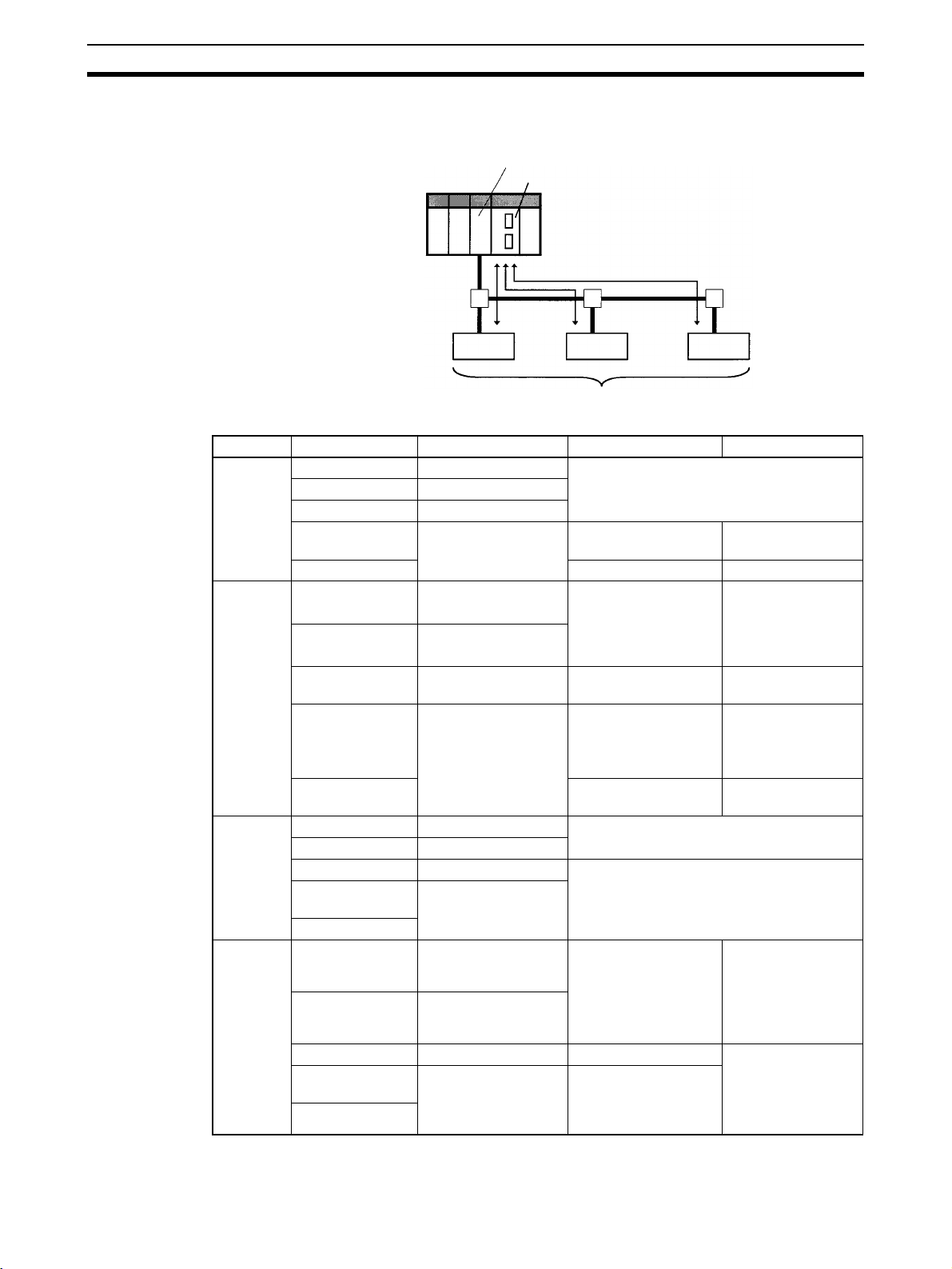
1-1-2 Applicable Units and DeviceNet Functions
Remote I/O Master
DeviceNet Unit (Master)
CPU Unit
Remote I/O communications
DeviceNet
Slaves
Item Master Model Without Configurator With Configurator
Max. No.
of Slave
nodes per
Master
Max. No.
of control
points per
Master
CS Series CS1W-DRM21(-V1) 63 nodes
CJ Series CJ1W-DRM21
CVM1, CV Series CVM1-DRM21-V1
CS Series,
C200HX/HG/HE
C200HS 32 nodes 63 nodes
CS Series CS1W-DRM21(-V1) 2,048 pts (64 input /64
CJ Series CJ1W-DRM21
C200HW-DRM21-V1 50 nodes 63 nodes
32,000 pts (500
output words) or
16,000 pts (500 input/
500 output words)
words x 4 blocks)
Max. No.
of I/O
points per
Slave controllable by
Master
Remote I/
O allocation areas
CVM1, CV Series CVM1-DRM21-V1 2,048 pts (64 input/ 64
output words)
CS Series,
C200HX/HG/HE
C200HS 1,024 pts (32 input/32
CS Series CS1W-DRM21(-V1) 100 input/100 output words
CJ Series CJ1W-DRM21
CVM1, CV Series CVM1-DRM21-V1 32 input/32 output words
CS Series,
C200HX/HG/HE
C200HS
CS Series CS1W-DRM21(-V1) CS/CJ DeviceNet
CJ Series CJ1W-DRM21
CVM1, CV Series CVM1-DRM21-V1 DeviceNet Area User-allocated
CS Series,
C200HX/HG/HE
C200HS
C200HW-DRM21-V1 1,600 pts (50 input/50
output words)
output words)
C200HW-DRM21-V1
words in CIO Area,
and user-allocated
words in CIO Area,
DM Area, and other
areas.
C200HW-DRM21-V1 C200H DeviceNet
words in CIO Area
(including dedicated
words/ bits)
6,400 (100 words x
4 blocks
Without messages:
4,800 pts
With messages:
1,600 pts
1,280
User-allocated
words in CIO Area,
DM Area, and other
areas.
words in CIO Area,
DM Area, and other
areas.
6

Overview of DeviceNet Section 1-1
Remote I/O Slave (only Units Mounted in a PLC)
DeviceNet Unit (Master)
CPU Unit
IN area OUT area
Item CPU Unit to
Max. No. of I/O pts
per Slave
Allocation areas in
the CPU Unit to
which this Slave is
mounted
Remote I/O communications
DeviceNet Unit (Slave)
DeviceNet
Slaves
CPU Unit
IN area
Unit Model Without the
which a Slave is
Configurator
mounted
CS Series CS1W-DRM21(-V1) 32 pts (1 input/
1 output word) or
CJ Series CJ1W-DRM21
3,200 pts (100
input/100 output
words)
CS Series,
C200HW-DRT21 1,024 pts (32 input/32 output words)
C200HX/HG/HE
CQM1H
CQM1-DRT21 32 pts (1 input/1 output word)
CQM1 Series
CS Series CS1W-DRM21(-V1) CIO, WR, DM, EM, HR
CJ Series CJ1W-DRM21
CS Series,
C200HW-DRT21 CIO, DM, EM, AR, LR, T/C
C200HX/HG/HE
CQM1H
CQM1-DRT21 CIO
CQM1 Series
OUT area
With the
Configurator
4,800 pts
(100 input words x
2/100 output words
x 1)
7
Overview of DeviceNet Section 1-1
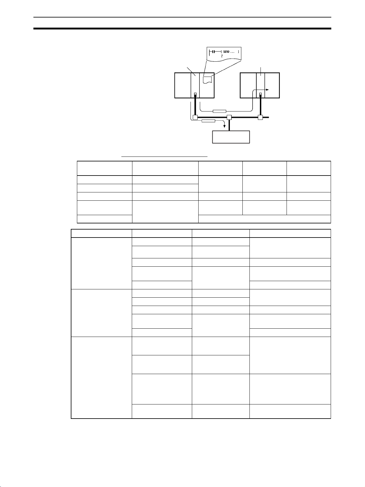
Message Communications
Master Master
RS-232C
Interface Unit
Communications Instructions
Master Unit model Send Receive FINS
commands
CS Series CS1W-DRM21(-V1) SEND(192) RECV(193) CMND(194)
CJ Series CJ1W-DRM21
CVM1, CV Series CVM1-DRM21-V1 SEND(192) RECV(193) CMND(194)
CS Series,
C200HX/HG/HE
C200HS ---
C200HW-DRM21-V1 None None IOWR
Item Master model Model Capacity
Max. No. of nodes per
Master for message
communications using
FINS commands
Max. No. of nodes per
Master for message
communications using
explicit messages
Max. message length CS Series CS1W-DRM21(-V1) SEND(192): 267 words
CS Series CS1W-DRM21(-V1) 62 nodes
CJ Series CJ1W-DRM21
CVM1, CV Series CVM1-DRM21-V1 8 nodes
CS Series,
C200HX/HG/HE
C200HS Not supported
CS Series CS1W-DRM21(-V1) 63 nodes
CJ Series CJ1W-DRM21
CVM1, CV Series CVM1-DRM21-V1 63 nodes
CS Series, C200HX/
HG/HE
C200HS Not supported
CJ Series CJ1W-DRM21
CVM1, CV Series CVM1-DRM21-V1 SEND(192): 76 words
CS Series,
C200HX/HG/HE
C200HW-DRM21-V1 8 nodes
C200HW-DRM21-V1 63 nodes
C200HW-DRM21-V1 IOWR(223): 160 bytes (start-
(Node address 0 cannot be
used in FINS communications.)
RECV(193): 269 words
CMND(194): 542 bytes (start-
ing with command code)
RECV(193): 78 words
CMND(194): 160 bytes
(starting with command code)
ing with command code)
Note FINS message communications are supported between any two PLCs with a
CS/CJ-series DeviceNet Unit (CS1W-DRM21(-V1)/CJ1W-DRM21). They are
not supported for PLCs with a C200H DeviceNet Master Unit (C200HW-
8

Overview of DeviceNet Section 1-1
DRM21-V1) or a CVM1/CV-series DeviceNet Master Unit (CVM1-DRM21V1). Refer to
Communications Software Switches and Communications Status
Dedicated words in the CPU Unit are allocated for DeviceNet communications
software switches and status.
Master
6-3 Using FINS Message Communications for details.
Software
switches
Status area
Control scan list registration/clearing, remote I/O
communications start/stop, and other parameters
Enables monitoring communications errors, communications
status of Masters, registered Slave data, normal Slave data,
etc.
1-1-3 Masters
PLC Model Mountable position Master/Slave
function
CS Series CS1W-DRM21(-V1)
CJ Series CJ1W-DRM21 CPU Rack or Expansion
CVM1/CV Series CVM1-DRM21-V1
CS Series C200HW-DRM21-V1
C200HX/HG/HE 10 or 16
C200HS 10
DeviceNet Unit
DeviceNet Master
Unit
DeviceNet Master
Unit
CPU or Expansion CPU
Rack (Classified as CPU
Bus Units)
Rack (Classified as CPU
Bus Units)
CPU or Expansion CPU
Rack (Classified as CPU
Bus Units)
CPU Rack or Expansion
I/O Rack (Classified as
Special I/O Units)
Master and Slave 16
Master only 16 1
Maximum number of
Configurator
16
mountable units
With
Without
Configurator
1-1-4 Types of Slave
The following classifications are used for DeviceNet Slaves.
• General-purpose Slaves:
Slave with I/O functions for I/O that uses an ordinary connector connected
to a communications cable.
• Environment-resistant Slaves:
Slave with I/O functions for I/O that uses a round, waterproof connector
connected to a communications cable.
• Special Slaves:
Slave with functions not related to I/O (e.g., message communications) for
I/O that uses an ordinary connector connected to a communications
cable.
9
Loading...