


 Loading...
Omron CJ1W-C413, CJ1W-C233, CJ1W-C113, CJ1W-C433, CJ1W-C213 OPERATION MANUAL
...Cat. No. W397-E1-07
SYSMAC
CJ1W-NC113/213/413/133/233/433
Position Control Units
OPERATION MANUAL
CJ1W-NC113/213/413/133/233/433
Position Control Units
Operation Manual
Revised February 2008
iv
Notice:
OMRON products are manufactured for use according to proper procedures by a qualified operator and only for the purposes described in this manual.
The following conventions are used to indicate and classify precautions in this manual. Always heed the information provided with them. Failure to heed precautions can result in injury to people or damage to property.
!DANGER Indicates an imminently hazardous situation which, if not avoided, will result in death or serious injury. Additionally, there may be severe property damage.
!WARNING Indicates a potentially hazardous situation which, if not avoided, could result in death or serious injury. Additionally, there may be severe property damage.
!Caution Indicates a potentially hazardous situation which, if not avoided, may result in minor or moderate injury, or property damage.
OMRON Product References
All OMRON products are capitalized in this manual. The word “Unit” is also capitalized when it refers to an OMRON product, regardless of whether or not it appears in the proper name of the product.
The abbreviation “Ch,” which appears in some displays and on some OMRON products, often means “word” and is abbreviated “Wd” in documentation in this sense.
The abbreviation “PLC” means Programmable Controller. “PC” is used, however, in some Programming Device displays to mean Programmable Controller.
Visual Aids
The following headings appear in the left column of the manual to help you locate different types of information.
Note Indicates information of particular interest for efficient and convenient operation of the product.
1,2,3... 1. Indicates lists of one sort or another, such as procedures, checklists, etc.
OMRON, 2001
All rights reserved. No part of this publication may be reproduced, stored in a retrieval system, or transmitted, in any form, or by any means, mechanical, electronic, photocopying, recording, or otherwise, without the prior written permission of OMRON.
No patent liability is assumed with respect to the use of the information contained herein. Moreover, because OMRON is constantly striving to improve its high-quality products, the information contained in this manual is subject to change without notice. Every precaution has been taken in the preparation of this manual. Nevertheless, OMRON assumes no responsibility for errors or omissions. Neither is any liability assumed for damages resulting from the use of the information contained in this publication.
v
Unit Versions of CJ-series Position Control Units
Unit Versions
A “Unit version” has been introduced to manage Position Control Units in the CJ Series according to differences in functionality accompanying Unit upgrades.
Notation of Unit Versions |
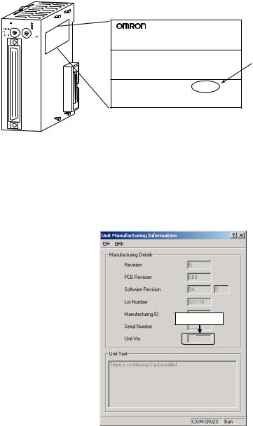
The Unit version is given to the right of the lot number on the nameplate of the |
on Products |
applicable Position Control Units, as shown below. |
CJ-series Position Control Unit
NC113
XRUN ERC
|
23 |
|
|
ERH |
|
|
|
234 |
|||
1 |
|
4 |
01 |
||
|
5 |
|
5 |
||
0 |
|
6 |
|
||
|
9 |
|
|
76 |
|
|
7 |
|
98 |
||
|
8 |
|
|
||
20 |
|
|
20 |
|
|
CN1 |
|
|
|
|
|
1 |
|
|
1 |
|
|
|
|
|
X |
|
|
Product nameplate
CJ1W-NC113
NC UNIT
Unit version
Example for Unit version 2.3
Lot No. 031001 |
0000 Ver.2.3 |
OMRON Corporation |
MADE IN JAPAN |
Confirming Unit Versions with Support Software
1,2,3...
The Unit version of the Position Control Units begins at version 2.0.
The Unit version can be confirmed in Unit Manufacturing Information of CXProgrammer version 4.0 or higher using the following procedure.
1.In the IO Table Window, right-click the Position Control Unit and select Unit
Manufacturing information.
2.The following Unit Manufacturing information Dialog Box will be displayed.
Unit version
2.3
Example: Unit version 2.3 will be displayed in the Unit Manufacturing information Dialog Box.
Use the above display to confirm the Unit version of the Position Control Unit.
vi
Using the Unit Version |
The following Unit version label is provided with the Position Control Unit. |
Label |
This label can be attached to the front of the Position Control Unit to differenti- |
|
|
|
ate between Position Control Units of different Unit versions. |
Unit Version Notation
In this manual, the Unit version of a Position Control Unit is given as shown in the following table.
Product nameplate |
Notation used in this manual |
Special remarks |
|
|
|
|
|
Ver. 2.0 or later number |
CJ-series Position Control Unit Ver. 2.0 or later. |
Information without reference |
|
shown to the right of the |
|
to specific Unit versions |
|
lot number |
|
applies to all versions of the |
|
|
|
Unit. |
|
Blank to the right of lot |
Pre-Ver. 2.0 CJ-series Position Control Unit |
||
|
|||
number |
|
|
|
|
|
|
Functions Supported by Each Unit Version of Position Control Unit
|
|
Unit Version |
Pre-Ver. 2.0 |
Ver. 2.0 |
Ver. 2.3 |
|
|
|
|
|
|
Internal system software version |
1.0 |
2.0 |
2.3 |
||
|
|
|
|
|
|
CJ-series Position Control Units |
CJ1W-NC113/133/213/233/413/433 |
|
|||
|
|
|
|
|
|
Functions |
Changing the acceleration |
Not supported |
Supported |
Supported |
|
|
|
for a multiple start during |
|
|
|
|
|
relative movement or |
|
|
|
|
|
absolute movement in |
|
|
|
|
|
direct operation |
|
|
|
|
|
|
|
|
|
|
|
Changing accelera- |
Not supported |
Supported |
Supported |
|
|
tion/deceleration time dur- |
|
|
|
|
|
ing jog operation |
|
|
|
|
|
|
|
|
|
|
|
Setting acceleration/decel- |
Not supported |
Supported |
Supported |
|
|
eration time for axis |
|
|
|
|
|
parameters until the target |
|
|
|
|
|
speed is reached |
|
|
|
|
|
Easy backup function |
Not supported |
Supported |
Supported |
|
|
|
|
|
|
|
|
Setting number of unused |
Not supported |
Not supported |
Supported |
|
|
axes |
|
|
|
|
|
Setting CW/CCW pulse |
Not supported |
Not supported |
Supported |
|
|
output direction |
|
|
|
|
|
|
|
|
|
|
|
Setting origin search pat- |
Not supported |
Not supported |
Supported |
|
|
tern |
|
|
|
|
|
|
|
|
|
|
|
Position data setting when |
Not supported |
Not supported |
Supported |
|
|
origin signal stops |
|
|
|
|
|
Setting jog operation |
Not supported |
Not supported |
Supported |
|
|
|
|
|
|
|
|
Setting deviation counter |
Not supported |
Not supported |
Supported |
|
|
reset output signal |
|
|
|
|
|
Checking parameters and |
Not supported |
Not supported |
Supported |
|
|
data at startup |
|
|
|
|
|
|
|
|
|
Support Software |
CX-Position Ver. 1.0 |
CX-Position Ver. 1.0 (See note 2.) |
CX-Position Ver. 1.0 (See note 2.) |
||
|
|
|
or later |
CX-Position Ver. 2.0 or later |
CX-Position Ver. 2.0 (See note 2.) |
|
|
|
|
|
CX-Position Ver. 2.1 (See note 2.) |
|
|
|
|
|
CX-Position Ver. 2.2 or later |
Note 1. The Position Control Unit must be installed with CJ1-H or CJ1M CPU Unit to use the above functions supported for Position Control Unit Ver. 2.0. These functions cannot be used if the Position Control Unit is installed with a CJ1 CPU Unit.
2.With CX-Position Ver. 1.0, new functions added to Position Control Units Ver. 2.0 or higher cannot be used.
vii
Checking Position Control Unit Version and Internal System Software Version
Position Control Units have an internal system software version in addition to the Unit version used by CS/CJ-series Units to distinguish functions. The following table shows the relationship between the Position Control Unit’s Unit version and internal system software version.
Version type |
Unit version |
Internal system software version |
|
|
|
Details |
Version code for distinguishing functions sup- |
Version code for internal system software. |
|
ported for CS/CJ-series Units. |
|
|
|
|
Checking method |
The Unit version code is displayed to the right |
Press the Ctrl + V Keys while the CX-Position |
|
of the lot number on the nameplate attached |
NC Monitor Screen is displayed. |
|
to the Position Control Unit. |
|
|
The Unit version code can also be checked |
|
|
from CX-Programmer Ver. 4.0 in Unit Manu- |
|
|
facturing information of the I/O Table Window. |
|
|
|
|
Correlation |
Pre-Ver. 2.0 |
1.0 |
|
|
|
|
Ver. 2.0 |
2.0 |
|
|
|
|
Ver. 2.3 |
2.3 |
|
|
|
viii
Version Upgrade Information
The following tables outline changes made for the most recent version upgrade for SYSMAC CJ-Series Position Control Units.
■ Enhanced Functions for Unit Version 2.0
Changing Multiple-start Acceleration for Relative and Absolute Movement during Direct Operation
Previous version |
Present version (Ver. 2.0 or later) |
|
|
When executing multiple starts during direct |
When executing multiple starts during direct operation, the acceler- |
operation, the acceleration/deceleration times |
ation time set for each of the multiple starts is used and the decel- |
set for the first start were used. |
eration time set for the first start is used. |
|
|
Changing Accelerations/Decelerations and Changing Deceleration Following Interrupt Inputs for Interrupt Feeding during Direct Operation
Previous version |
Present version (Ver. 2.0 or later) |
|
|
The speed command could be changed as |
The acceleration/deceleration times can be changed and changes |
long as it was done before the interrupt signal |
can be made with the speed command as long as the changes are |
was input. If an acceleration/deceleration time |
made before the interrupt signal is input. The acceleration/deceler- |
was changed, the change would not be effec- |
ation times can also be changed during acceleration and decelera- |
tive until the next interrupt feed command. The |
tion. The deceleration time set for when the interrupt input occurs is |
acceleration/deceleration times set for the first |
used following interrupt signal input. |
start were used for speed changes. The decel- |
|
eration time set for the first start was used after |
|
interrupt signal input. |
|
Allowing Changes to Acceleration/Deceleration Time during Jogging
Previous version |
Present version (Ver. 2.0 or later) |
|
|
The only speed changes allowed during jog- |
In addition to changes made during JOG operation with the speed |
ging were those made with the speed com- |
command, speed changes can also be made during JOG operation |
mand. If acceleration/deceleration times |
by changing the acceleration/deceleration times. Accelera- |
changed, the changes were not effective until |
tions/decelerations can also be changed during acceleration/decel- |
the next JOG command. The deceleration time |
eration. Accelerations/decelerations can also be changed during |
set when the JOG operation was started was |
acceleration/deceleration to a fixed speed. The deceleration time |
used for accelerations/decelerations for speed |
set when the stopping the JOG operation is executed is used for |
changes as well as for JOG stops or decelera- |
JOG stops or deceleration stops. |
tion stops. |
|
Setting Acceleration/Deceleration Time in Axis Parameters as Time Required to Reach Target Speed
Previous version |
Present version |
|
|
|
|
Acceleration/deceleration times could be set |
The acceleration/deceleration time can be set in one of the follow- |
|
only as the time required for each axis to go |
ing ways. |
|
from the initial speed to the maximum speed. |
• |
Set as the time required for each axis to go from the initial |
|
• |
speed to the maximum speed (previous setting method). |
|
Set as the time required for each axis to go from the present |
|
|
|
speed to the target speed. (This simplifies calculating acceler- |
|
|
ation/deceleration times.) |
Addition of Easy Backup Function
Previous version |
Present version |
|
|
|
|
There was no easy backup function. |
The easy backup function of the CPU Unit can be used to automat- |
|
|
ically back up and restore the following data from/to flash memory |
|
|
in the PCU along with all data from the CPU Unit using a Memory |
|
|
Card in the CPU Unit. It can also compare the data. This makes it |
|
|
easier to back up all PLC data or to prepare backup data in case |
|
|
Units are replaced. |
|
|
• |
Axis parameters |
|
• Sequence data |
|
|
• Speed data |
|
|
• |
Acceleration/deceleration time data |
|
• |
Dwell time data |
|
• Zone data |
|
|
Note Data for all Unit axes is stored at the same time. |
|
|
|
|
ix
■ Enhanced Functions in the Upgrade from Unit Version 2.0 to
Unit Version 2.3
Setting the Number of Unused Axes
Previous version |
Present version (Ver. 2.3 or later) |
|
|
Emergency stop input wiring was also required |
Setting the number of unused axes in the common parameters |
for unused axes. |
eliminates the need for emergency stop input wiring for unused |
|
axes. |
Setting the CW/CCW Pulse Output Direction
Previous version |
Present version (Ver. 2.3 or later) |
|
|
The pulse output direction could not be |
Bits for reversing the output direction have been added to the axis |
changed. |
parameter areas. Specifying reversal reverses the output section |
|
and is effective for applications using the same wiring but reversed |
|
coordinates. |
|
|
Addition of Origin Search Pattern Setting
Previous version |
Present version (Ver. 2.3 or later) |
|
|
Operation was uneven if a return was per- |
Reverse mode 3 has been added to enable stopping at the origin |
formed at the origin proximity and operation |
signal at the proximity speed when a return is performed at the ori- |
immediately stopped at the origin input signal. |
gin proximity. |
|
|
Setting the Position Data When the Origin Signal Stops
Previous version |
Present version (Ver. 2.3 or later) |
|
|
The stopping point was always 0. |
The value of the stopping point can be set. Applications in which |
|
the stopping point is not 0 do not require presetting the present |
|
position. |
|
|
Jog Operation Setting
Previous version |
Present version (Ver. 2.3 or later) |
|
|
|
|
Axes could not be operated from the CX-Posi- |
The following operations are possible in combination with CX-Posi- |
|
tion. |
tion version 2.2, which will be included with CX-One version 1.1 |
|
|
scheduled for sale November 2005. |
|
|
• Parameter settings for jog operation (acceleration/deceleration |
|
|
|
time, run signal allocation) |
|
• |
Error reset |
|
• |
Keyboard lock/unlock button |
|
• RUN signal ON/OFF |
|
|
• |
+Jog/−jog |
|
• |
Monitoring the present position, limit sensor, and other functions |
|
|
while the jog operation is being performed. |
|
|
|
Deviation Counter Reset Output Signal Setting
Previous version |
Present version (Ver. 2.3 or later) |
|
|
The deviation counter reset output could not |
The following operations are possible in combination with CX-Posi- |
be turned ON and OFF from the CX-Position. |
tion version 2.2, which will be included with CX-One version 1.1 |
|
scheduled for sale November 2005. |
|
• Turning ON and OFF the deviation counter reset output. |
|
|
Checking Parameters and Data at Startup
Previous version |
Present version (Ver. 2.3 or later) |
|
|
Parameters and data were not checked at star- |
Parameters and data for up to four axes can be checked and up to |
tup. |
four errors (i.e., one per axis) can be detected and output. |
|
|
x
TABLE OF CONTENTS
PRECAUTIONS . . . . . . . . . . . . . . . . . . . . . . . . . . . . . . . . |
xxi |
|
1 |
Intended Audience . . . . . . . . . . . . . . . . . . . . . . . . . . . . . . . . . . . . . . . . . . . . . . . . . |
xxii |
2 |
General Precautions . . . . . . . . . . . . . . . . . . . . . . . . . . . . . . . . . . . . . . . . . . . . . . . . |
xxii |
3 |
Safety Precautions. . . . . . . . . . . . . . . . . . . . . . . . . . . . . . . . . . . . . . . . . . . . . . . . . . |
xxii |
4 |
Operating Environment Precautions . . . . . . . . . . . . . . . . . . . . . . . . . . . . . . . . . . . . |
xxiv |
5 |
Application Precautions . . . . . . . . . . . . . . . . . . . . . . . . . . . . . . . . . . . . . . . . . . . . . |
xxv |
6 Conformance to EC Directives . . . . . . . . . . . . . . . . . . . . . . . . . . . . . . . . . . . . . . . . |
xxvii |
|
SECTION 1 |
|
|
Introduction. . . . . . . . . . . . . . . . . . . . . . . . . . . . . . . . . . . . |
1 |
|
1-1 |
Features . . . . . . . . . . . . . . . . . . . . . . . . . . . . . . . . . . . . . . . . . . . . . . . . . . . . . . . . . . |
2 |
1-2 |
System Configuration . . . . . . . . . . . . . . . . . . . . . . . . . . . . . . . . . . . . . . . . . . . . . . . |
4 |
1-3 |
Basic Operations . . . . . . . . . . . . . . . . . . . . . . . . . . . . . . . . . . . . . . . . . . . . . . . . . . . |
5 |
1-4 |
List of Functions . . . . . . . . . . . . . . . . . . . . . . . . . . . . . . . . . . . . . . . . . . . . . . . . . . . |
8 |
1-5 |
Specifications . . . . . . . . . . . . . . . . . . . . . . . . . . . . . . . . . . . . . . . . . . . . . . . . . . . . . |
10 |
1-6 Comparison with Existing Models . . . . . . . . . . . . . . . . . . . . . . . . . . . . . . . . . . . . . |
13 |
|
1-7 |
Control System Principles. . . . . . . . . . . . . . . . . . . . . . . . . . . . . . . . . . . . . . . . . . . . |
14 |
SECTION 2 |
|
|
Basic Procedures . . . . . . . . . . . . . . . . . . . . . . . . . . . . . . . . |
17 |
|
SECTION 3 |
|
|
Installation and Wiring . . . . . . . . . . . . . . . . . . . . . . . . . . |
21 |
|
3-1 |
Nomenclature and Functions . . . . . . . . . . . . . . . . . . . . . . . . . . . . . . . . . . . . . . . . . |
22 |
3-2 |
Area Allocation . . . . . . . . . . . . . . . . . . . . . . . . . . . . . . . . . . . . . . . . . . . . . . . . . . . . |
23 |
3-3 |
Installation. . . . . . . . . . . . . . . . . . . . . . . . . . . . . . . . . . . . . . . . . . . . . . . . . . . . . . . . |
24 |
3-4 |
External I/O Circuitry . . . . . . . . . . . . . . . . . . . . . . . . . . . . . . . . . . . . . . . . . . . . . . . |
27 |
3-5 |
Wiring . . . . . . . . . . . . . . . . . . . . . . . . . . . . . . . . . . . . . . . . . . . . . . . . . . . . . . . . . . . |
37 |
3-6 Connection Examples for Different Types of Motor Driver . . . . . . . . . . . . . . . . . . |
47 |
|
3-7 Connection of Unused Axes . . . . . . . . . . . . . . . . . . . . . . . . . . . . . . . . . . . . . . . . . . |
61 |
|
3-8 |
Servo Relay Unit . . . . . . . . . . . . . . . . . . . . . . . . . . . . . . . . . . . . . . . . . . . . . . . . . . . |
63 |
SECTION 4 |
|
|
Data Areas . . . . . . . . . . . . . . . . . . . . . . . . . . . . . . . . . . . . . |
65 |
|
4-1 |
Overall Structure . . . . . . . . . . . . . . . . . . . . . . . . . . . . . . . . . . . . . . . . . . . . . . . . . . . |
66 |
4-2 |
Data Areas. . . . . . . . . . . . . . . . . . . . . . . . . . . . . . . . . . . . . . . . . . . . . . . . . . . . . . . . |
68 |
4-3 |
Common Parameter Area . . . . . . . . . . . . . . . . . . . . . . . . . . . . . . . . . . . . . . . . . . . . |
71 |
4-4 |
Axis Parameter Area . . . . . . . . . . . . . . . . . . . . . . . . . . . . . . . . . . . . . . . . . . . . . . . . |
75 |
4-5 |
Operating Memory Area . . . . . . . . . . . . . . . . . . . . . . . . . . . . . . . . . . . . . . . . . . . . . |
95 |
4-6 |
Operating Data Area . . . . . . . . . . . . . . . . . . . . . . . . . . . . . . . . . . . . . . . . . . . . . . . . |
98 |
4-7 |
Memory Operation Data . . . . . . . . . . . . . . . . . . . . . . . . . . . . . . . . . . . . . . . . . . . . . |
101 |
4-8 |
Zone Data Area . . . . . . . . . . . . . . . . . . . . . . . . . . . . . . . . . . . . . . . . . . . . . . . . . . . . |
104 |
4-9 Examples of Parameter Settings . . . . . . . . . . . . . . . . . . . . . . . . . . . . . . . . . . . . . . . |
105 |
|
SECTION 5 |
|
|
Transferring and Saving Data . . . . . . . . . . . . . . . . . . . . . |
113 |
|
5-1 Transferring and Saving Data . . . . . . . . . . . . . . . . . . . . . . . . . . . . . . . . . . . . . . . . . |
114 |
|
5-2 Writing Data with the WRITE DATA Bit . . . . . . . . . . . . . . . . . . . . . . . . . . . . . . . . |
121 |
|
5-3 Reading Data with the READ DATA Bit . . . . . . . . . . . . . . . . . . . . . . . . . . . . . . . . |
127 |
|
5-4 Writing Data with IOWR . . . . . . . . . . . . . . . . . . . . . . . . . . . . . . . . . . . . . . . . . . . . |
132 |
|
5-5 Reading Data with IORD . . . . . . . . . . . . . . . . . . . . . . . . . . . . . . . . . . . . . . . . . . . . |
139 |
|
5-6 |
Saving Data . . . . . . . . . . . . . . . . . . . . . . . . . . . . . . . . . . . . . . . . . . . . . . . . . . . . . . . |
143 |
5-7 Transferring Data with CX-Position . . . . . . . . . . . . . . . . . . . . . . . . . . . . . . . . . . . . |
145 |
|
xi
TABLE OF CONTENTS
SECTION 6 |
|
|
Defining the Origin . . . . . . . . . . . . . . . . . . . . . . . . . . . . . . |
147 |
|
6-1 |
Outline . . . . . . . . . . . . . . . . . . . . . . . . . . . . . . . . . . . . . . . . . . . . . . . . . . . . . . . . . . |
148 |
6-2 |
Origin Search Procedure . . . . . . . . . . . . . . . . . . . . . . . . . . . . . . . . . . . . . . . . . . . . |
149 |
6-3 |
Data Settings Required for Origin Search . . . . . . . . . . . . . . . . . . . . . . . . . . . . . . . |
150 |
6-4 |
Origin Search Operation . . . . . . . . . . . . . . . . . . . . . . . . . . . . . . . . . . . . . . . . . . . . |
153 |
6-5 |
Origin Search Timing Charts. . . . . . . . . . . . . . . . . . . . . . . . . . . . . . . . . . . . . . . . . |
169 |
6-6 |
Present Position Preset. . . . . . . . . . . . . . . . . . . . . . . . . . . . . . . . . . . . . . . . . . . . . . |
174 |
6-7 |
Origin Return . . . . . . . . . . . . . . . . . . . . . . . . . . . . . . . . . . . . . . . . . . . . . . . . . . . . . |
175 |
6-8 |
Z-phase Margin . . . . . . . . . . . . . . . . . . . . . . . . . . . . . . . . . . . . . . . . . . . . . . . . . . . |
177 |
SECTION 7 |
|
|
Direct Operation . . . . . . . . . . . . . . . . . . . . . . . . . . . . . . . . |
179 |
|
7-1 |
Outline . . . . . . . . . . . . . . . . . . . . . . . . . . . . . . . . . . . . . . . . . . . . . . . . . . . . . . . . . . |
180 |
7-2 |
Direct Operation Procedure . . . . . . . . . . . . . . . . . . . . . . . . . . . . . . . . . . . . . . . . . . |
181 |
7-3 |
Setting Data for Direct Operation . . . . . . . . . . . . . . . . . . . . . . . . . . . . . . . . . . . . . |
181 |
7-4 |
Operations with Direct Operation . . . . . . . . . . . . . . . . . . . . . . . . . . . . . . . . . . . . . |
183 |
7-5 |
Direct Operation Timing Charts . . . . . . . . . . . . . . . . . . . . . . . . . . . . . . . . . . . . . . |
186 |
7-6 |
Acceleration/Deceleration . . . . . . . . . . . . . . . . . . . . . . . . . . . . . . . . . . . . . . . . . . . |
188 |
7-7 |
Sample Program. . . . . . . . . . . . . . . . . . . . . . . . . . . . . . . . . . . . . . . . . . . . . . . . . . . |
191 |
SECTION 8 |
|
|
Memory Operation . . . . . . . . . . . . . . . . . . . . . . . . . . . . . . |
197 |
|
8-1 |
Outline . . . . . . . . . . . . . . . . . . . . . . . . . . . . . . . . . . . . . . . . . . . . . . . . . . . . . . . . . . |
198 |
8-2 |
Memory Operation Procedure . . . . . . . . . . . . . . . . . . . . . . . . . . . . . . . . . . . . . . . . |
202 |
8-3 |
Setting Data for Memory Operation . . . . . . . . . . . . . . . . . . . . . . . . . . . . . . . . . . . |
202 |
8-4 |
Positioning Sequences . . . . . . . . . . . . . . . . . . . . . . . . . . . . . . . . . . . . . . . . . . . . . . |
204 |
8-5 |
Completion Codes . . . . . . . . . . . . . . . . . . . . . . . . . . . . . . . . . . . . . . . . . . . . . . . . . |
211 |
8-6 |
Linear Interpolation . . . . . . . . . . . . . . . . . . . . . . . . . . . . . . . . . . . . . . . . . . . . . . . . |
217 |
8-7 |
Transferring Positioning Sequences . . . . . . . . . . . . . . . . . . . . . . . . . . . . . . . . . . . |
220 |
8-8 |
Timing Chart for Memory Operation . . . . . . . . . . . . . . . . . . . . . . . . . . . . . . . . . . |
223 |
8-9 |
Acceleration/Deceleration . . . . . . . . . . . . . . . . . . . . . . . . . . . . . . . . . . . . . . . . . . . |
226 |
8-10 |
Sample Program. . . . . . . . . . . . . . . . . . . . . . . . . . . . . . . . . . . . . . . . . . . . . . . . . . . |
229 |
SECTION 9 |
|
|
Other Operations. . . . . . . . . . . . . . . . . . . . . . . . . . . . . . . . |
233 |
|
9-1 |
Jogging. . . . . . . . . . . . . . . . . . . . . . . . . . . . . . . . . . . . . . . . . . . . . . . . . . . . . . . . . . |
235 |
9-2 |
Teaching. . . . . . . . . . . . . . . . . . . . . . . . . . . . . . . . . . . . . . . . . . . . . . . . . . . . . . . . . |
237 |
9-3 |
Interrupt Feeding . . . . . . . . . . . . . . . . . . . . . . . . . . . . . . . . . . . . . . . . . . . . . . . . . . |
239 |
9-4 |
Forced Interrupt . . . . . . . . . . . . . . . . . . . . . . . . . . . . . . . . . . . . . . . . . . . . . . . . . . . |
242 |
9-5 |
Deceleration Stop. . . . . . . . . . . . . . . . . . . . . . . . . . . . . . . . . . . . . . . . . . . . . . . . . . |
244 |
9-6 |
Override . . . . . . . . . . . . . . . . . . . . . . . . . . . . . . . . . . . . . . . . . . . . . . . . . . . . . . . . . |
249 |
9-7 |
Error Counter Reset Output and Origin Adjustment Command Output . . . . . . . . |
252 |
9-8 |
Backlash Compensation. . . . . . . . . . . . . . . . . . . . . . . . . . . . . . . . . . . . . . . . . . . . . |
256 |
9-9 |
Software Limit . . . . . . . . . . . . . . . . . . . . . . . . . . . . . . . . . . . . . . . . . . . . . . . . . . . . |
258 |
9-10 |
Stop Function. . . . . . . . . . . . . . . . . . . . . . . . . . . . . . . . . . . . . . . . . . . . . . . . . . . . . |
261 |
9-11 |
Easy Backup Function (Ver. 2.0 or later). . . . . . . . . . . . . . . . . . . . . . . . . . . . . . . . |
262 |
xii
TABLE OF CONTENTS
SECTION 10 |
|
|
Program Examples . . . . . . . . . . . . . . . . . . . . . . . . . . . . . . |
267 |
|
10-1 |
Operating Procedures for Program Examples. . . . . . . . . . . . . . . . . . . . . . . . . . . . . |
268 |
10-2 |
Memory Operation . . . . . . . . . . . . . . . . . . . . . . . . . . . . . . . . . . . . . . . . . . . . . . . . . |
270 |
10-3 |
Direct Operation . . . . . . . . . . . . . . . . . . . . . . . . . . . . . . . . . . . . . . . . . . . . . . . . . . . |
285 |
10-4 |
Two-axis Linear Interpolation. . . . . . . . . . . . . . . . . . . . . . . . . . . . . . . . . . . . . . . . . |
292 |
10-5 |
Origin Search Using Limit Input . . . . . . . . . . . . . . . . . . . . . . . . . . . . . . . . . . . . . . |
298 |
10-6 |
Changing Speed Using an Override during Pulse Output. . . . . . . . . . . . . . . . . . . . |
300 |
10-7 |
Transferring and Saving Data . . . . . . . . . . . . . . . . . . . . . . . . . . . . . . . . . . . . . . . . . |
303 |
SECTION 11 |
|
|
Troubleshooting . . . . . . . . . . . . . . . . . . . . . . . . . . . . . . . . |
309 |
|
11-1 |
Troubleshooting Tables . . . . . . . . . . . . . . . . . . . . . . . . . . . . . . . . . . . . . . . . . . . . . . |
310 |
11-2 |
Introduction . . . . . . . . . . . . . . . . . . . . . . . . . . . . . . . . . . . . . . . . . . . . . . . . . . . . . . . |
317 |
11-3 |
LED Error Indicators . . . . . . . . . . . . . . . . . . . . . . . . . . . . . . . . . . . . . . . . . . . . . . . |
319 |
11-4 |
Reading Error Codes. . . . . . . . . . . . . . . . . . . . . . . . . . . . . . . . . . . . . . . . . . . . . . . . |
321 |
11-5 |
Error Code Lists . . . . . . . . . . . . . . . . . . . . . . . . . . . . . . . . . . . . . . . . . . . . . . . . . . . |
322 |
11-6 |
Releasing Pulse Output Prohibition and Resetting After Errors. . . . . . . . . . . . . . . |
338 |
11-7 |
Error Display at the CPU . . . . . . . . . . . . . . . . . . . . . . . . . . . . . . . . . . . . . . . . . . . . |
341 |
11-8 |
Reading Error Information with CX-Position. . . . . . . . . . . . . . . . . . . . . . . . . . . . . |
341 |
SECTION 12 |
|
|
Maintenance and Inspection . . . . . . . . . . . . . . . . . . . . . . |
343 |
|
12-1 |
Inspection . . . . . . . . . . . . . . . . . . . . . . . . . . . . . . . . . . . . . . . . . . . . . . . . . . . . . . . . |
344 |
12-2 |
Routine Inspections. . . . . . . . . . . . . . . . . . . . . . . . . . . . . . . . . . . . . . . . . . . . . . . . . |
344 |
12-3 |
Handling Precautions . . . . . . . . . . . . . . . . . . . . . . . . . . . . . . . . . . . . . . . . . . . . . . . |
345 |
12-4 |
Procedure for Replacing a PCU . . . . . . . . . . . . . . . . . . . . . . . . . . . . . . . . . . . . . . . |
345 |
Appendices |
|
|
A |
Performance Characteristics . . . . . . . . . . . . . . . . . . . . . . . . . . . . . . . . . . . . . . . . . |
347 |
B |
Estimating Times and Pulses for Acceleration/Deceleration . . . . . . . . . . . . . . . . . |
353 |
C |
Common Parameter Area . . . . . . . . . . . . . . . . . . . . . . . . . . . . . . . . . . . . . . . . . . . . |
357 |
D |
Error Code Lists . . . . . . . . . . . . . . . . . . . . . . . . . . . . . . . . . . . . . . . . . . . . . . . . . . . |
359 |
E |
Parameter Coding Sheets . . . . . . . . . . . . . . . . . . . . . . . . . . . . . . . . . . . . . . . . . . . . |
363 |
Index. . |
. . . . . . . . . . . . . . . . . . . . . . . . . . . . . . . . . . . . . . . . |
373 |
Revision History . . . . . . . . . . . . . . . . . . . . . . . . . . . . . . . . |
377 |
|
xiii
xiv

About this Manual:
This manual describes the operation of the CJ1W-NC113/NC133/NC213/NC233/NC413/NC433 Position Control Units and includes the sections described below.
Please read this manual carefully and be sure you understand the information provided before attempting to install and operate the CJ1W-NC113/NC133/NC213/NC233/NC413/NC433 Position Control Units.
Section 1 introduces the features of the Position Control Unit and explains the system configuration in which it is used.
Section 2 gives an overview of the procedures required to use the Position Control Unit.
Section 3 provides information on nomenclature and the function of each part, describes the procedures required for wiring and installation, and gives connection examples. Information on using Servo Relay Units is also provided.
Section 4 provides an overview of the parameter and data settings used in Position Control Unit operation and provides information on memory allocation.
Section 5 explains how to transfer and save parameters and data using the data transfer bits, the IOWR and IORD instructions, and CX-Position.
Section 6 explains the origin search and origin return operations.
Section 7 provides an overview of direct operation, describes the parameter and data settings required to perform direct operation, and gives sample programs.
Section 8 provides an overview of memory operation, describes the parameter and data settings required to perform memory operation, and gives sample programs.
Section 9 describes the following operations: Jogging, teaching, interrupt feeding, forced interrupt, deceleration stop, override, error counter reset output/origin-adjustment command output, backlash compensation, and software limits.
Section 10 provides examples of programs for using the Position Control Unit.
Section 11 describes how to diagnose and correct errors that can occur during operation.
Section 12 describes methods for maintaining the Position Control Unit.
The Appendices provide information on estimating times and pulses for acceleration and deceleration, a memory map for the common parameter area, error code lists, information on replacing the C200HW-NC@13, and parameter coding sheets.
!WARNING Failure to read and understand the information provided in this manual may result in personal injury or death, damage to the product, or product failure. Please read each section in its entirety and be sure you understand the information provided in the section and related sections before attempting any of the procedures or operations given.
xv
xvi

Read and Understand this Manual
Please read and understand this manual before using the product. Please consult your OMRON representative if you have any questions or comments.
Warranty and Limitations of Liability
WARRANTY
OMRON's exclusive warranty is that the products are free from defects in materials and workmanship for a period of one year (or other period if specified) from date of sale by OMRON.
OMRON MAKES NO WARRANTY OR REPRESENTATION, EXPRESS OR IMPLIED, REGARDING NONINFRINGEMENT, MERCHANTABILITY, OR FITNESS FOR PARTICULAR PURPOSE OF THE PRODUCTS. ANY BUYER OR USER ACKNOWLEDGES THAT THE BUYER OR USER ALONE HAS DETERMINED THAT THE PRODUCTS WILL SUITABLY MEET THE REQUIREMENTS OF THEIR INTENDED USE. OMRON DISCLAIMS ALL OTHER WARRANTIES, EXPRESS OR IMPLIED.
LIMITATIONS OF LIABILITY
OMRON SHALL NOT BE RESPONSIBLE FOR SPECIAL, INDIRECT, OR CONSEQUENTIAL DAMAGES, LOSS OF PROFITS OR COMMERCIAL LOSS IN ANY WAY CONNECTED WITH THE PRODUCTS, WHETHER SUCH CLAIM IS BASED ON CONTRACT, WARRANTY, NEGLIGENCE, OR STRICT LIABILITY.
In no event shall the responsibility of OMRON for any act exceed the individual price of the product on which liability is asserted.
IN NO EVENT SHALL OMRON BE RESPONSIBLE FOR WARRANTY, REPAIR, OR OTHER CLAIMS REGARDING THE PRODUCTS UNLESS OMRON'S ANALYSIS CONFIRMS THAT THE PRODUCTS WERE PROPERLY HANDLED, STORED, INSTALLED, AND MAINTAINED AND NOT SUBJECT TO CONTAMINATION, ABUSE, MISUSE, OR INAPPROPRIATE MODIFICATION OR REPAIR.
xvii

Application Considerations
SUITABILITY FOR USE
OMRON shall not be responsible for conformity with any standards, codes, or regulations that apply to the combination of products in the customer's application or use of the products.
At the customer's request, OMRON will provide applicable third party certification documents identifying ratings and limitations of use that apply to the products. This information by itself is not sufficient for a complete determination of the suitability of the products in combination with the end product, machine, system, or other application or use.
The following are some examples of applications for which particular attention must be given. This is not intended to be an exhaustive list of all possible uses of the products, nor is it intended to imply that the uses listed may be suitable for the products:
•Outdoor use, uses involving potential chemical contamination or electrical interference, or conditions or uses not described in this manual.
•Nuclear energy control systems, combustion systems, railroad systems, aviation systems, medical equipment, amusement machines, vehicles, safety equipment, and installations subject to separate industry or government regulations.
•Systems, machines, and equipment that could present a risk to life or property.
Please know and observe all prohibitions of use applicable to the products.
NEVER USE THE PRODUCTS FOR AN APPLICATION INVOLVING SERIOUS RISK TO LIFE OR PROPERTY WITHOUT ENSURING THAT THE SYSTEM AS A WHOLE HAS BEEN DESIGNED TO ADDRESS THE RISKS, AND THAT THE OMRON PRODUCTS ARE PROPERLY RATED AND INSTALLED FOR THE INTENDED USE WITHIN THE OVERALL EQUIPMENT OR SYSTEM.
PROGRAMMABLE PRODUCTS
OMRON shall not be responsible for the user's programming of a programmable product, or any consequence thereof.
xviii

Disclaimers
CHANGE IN SPECIFICATIONS
Product specifications and accessories may be changed at any time based on improvements and other reasons.
It is our practice to change model numbers when published ratings or features are changed, or when significant construction changes are made. However, some specifications of the products may be changed without any notice. When in doubt, special model numbers may be assigned to fix or establish key specifications for your application on your request. Please consult with your OMRON representative at any time to confirm actual specifications of purchased products.
DIMENSIONS AND WEIGHTS
Dimensions and weights are nominal and are not to be used for manufacturing purposes, even when tolerances are shown.
PERFORMANCE DATA
Performance data given in this manual is provided as a guide for the user in determining suitability and does not constitute a warranty. It may represent the result of OMRON's test conditions, and the users must correlate it to actual application requirements. Actual performance is subject to the OMRON Warranty and Limitations of Liability.
ERRORS AND OMISSIONS
The information in this manual has been carefully checked and is believed to be accurate; however, no responsibility is assumed for clerical, typographical, or proofreading errors, or omissions.
xix
xx
PRECAUTIONS
This section provides general precautions for using the Position Control Units and related devices.
The information contained in this section is important for the safe and reliable application of the Position Control Unit. You must read this section and understand the information contained before attempting to set up or operate a Position Control Unit.
1 |
Intended Audience . . . . . . . . . . . . . . . . . . . . . . . . . . . . . . . . . . . . . . . . . . . . . |
xxii |
||
2 |
General Precautions . . . . . . . . . . . . . . . . . . . . . . . . . . . . . . . . . . . . . . . . . . . . |
xxii |
||
3 |
Safety Precautions. . . . . . . . . . . . . . . . . . . . . . . . . . . . . . . . . . . . . . . . . . . . . . |
xxii |
||
4 |
Operating Environment Precautions . . . . . . . . . . . . . . . . . . . . . . . . . . . . . . . . |
xxiv |
||
5 |
Application Precautions . . . . . . . . . . . . . . . . . . . . . . . . . . . . . . . . . . . . . . . . . |
xxv |
||
6 |
Conformance to EC Directives . . . . . . . . . . . . . . . . . . . . . . . . . . . . . . . . . . . . |
xxvii |
||
|
6-1 |
Applicable Directives . . . . . . . . . . . . . . . . . . . . . . . . . . . . . . . . . . . . . |
xxvii |
|
|
|
6-1-1 |
Concepts . . . . . . . . . . . . . . . . . . . . . . . . . . . . . . . . . . . . . . . . |
xxvii |
|
|
6-1-2 |
Conformance to EC Directives . . . . . . . . . . . . . . . . . . . . . . . |
xxvii |
|
|
6-1-3 |
Installation within Control Panel . . . . . . . . . . . . . . . . . . . . . |
xxvii |
xxi
Intended Audience |
1 |
1 Intended Audience
This manual is intended for the following personnel, who must also have knowledge of electrical systems (an electrical engineer or the equivalent).
•Personnel in charge of installing FA systems.
•Personnel in charge of designing FA systems.
•Personnel in charge of managing FA systems and facilities.
2 General Precautions
The user must operate the product according to the performance specifications described in the operation manuals.
Before using the product under conditions which are not described in the manual or applying the product to nuclear control systems, railroad systems, aviation systems, vehicles, combustion systems, medical equipment, amusement machines, safety equipment, and other systems, machines, and equipment that may have a serious influence on lives and property if used improperly, consult your OMRON representative.
Make sure that the ratings and performance characteristics of the product are sufficient for the systems, machines, and equipment, and be sure to provide the systems, machines, and equipment with double safety mechanisms.
This manual provides information for using the Position Control Unit. Be sure to read this manual before attempting to use the Unit and keep this manual close at hand for reference during operation.
!WARNING It is extreme important that Position Control Units and related devices be used for the specified purpose and under the specified conditions, especially in applications that can directly or indirectly affect human life. You must consult with your OMRON representative before applying Position Control Units and related devices to the above mentioned applications.
3 Safety Precautions
!WARNING Never attempt to disassemble any Units while power is being supplied. Doing so may result in serious electric shock.
!WARNING Do not attempt to disassemble, repair, or modify any Units. Any attempt to do so may result in malfunction, fire, or electric shock.
!WARNING Never touch any of the terminals while power is being supplied. Doing so may result in serious electric shock.
!WARNING Provide safety measures in external circuits (i.e., not in the Programmable Controller or Position Control Unit) to ensure safety in the system if an abnormality occurs due to malfunction of the PLC, malfunction of the PCU (Position Control Unit), or external factors affecting the operation of the PLC or PCU. Not providing sufficient safety measures may result in serious accidents.
•Emergency stop circuits, interlock circuits, limit circuits, and similar safety measures must be provided in external control circuits.
xxii

Safety Precautions |
3 |
•The PLC will turn OFF all outputs when its self-diagnosis function detects any error or when a severe failure alarm (FALS) instruction is executed. As a countermeasure for such errors, external safety measures must be provided to ensure safety in the system.
•The PLC or PCU outputs may remain ON or OFF due to deposits on or burning of the output relays, or destruction of the output transistors. As a countermeasure for such problems, external safety measures must be provided to ensure safety in the system.
•When the 24-V DC output (service power supply to the PLC) is overloaded or short-circuited, the voltage may drop and result in the outputs being turned OFF. As a countermeasure for such problems, external safety measures must be provided to ensure safety in the system.
•External safety measures must also be taken to ensure safety in the event of unexpected operation when connecting or disconnecting the PCU’s connectors.
!Caution When positioning to a position determined using the teaching function, set the position designation setting in the positioning sequence to absolute positioning. If it is set to relative positioning, positioning will be performed to a position other than the one obtained with the teaching function.
!Caution Execute online edit only after confirming that no adverse effects will be caused by extending the cycle time. Otherwise, the input signals may not be readable.
!Caution Confirm the safety of the destination node before transferring a program to the node or changing the contents of I/O memory. Doing either of these without confirming safety may result in injury.
!Caution Do not save data into the flash memory during memory operation or while the motor is running. Otherwise, unexpected operation may be caused.
!Caution Do not reverse the polarity of the 24-V power supply. The polarity must be correct. Otherwise, the motor may start running unexpectedly and may not stop.
!Caution Make sure the unit version of the Position Control Unit is 2.3 or later before using the CW/CCW Pulse Output Selection Function. Otherwise, the pulse output may be in the opposite direction from what was intended and the machine may be damaged.
xxiii

Operating Environment Precautions |
4 |
4 Operating Environment Precautions
!Caution Do not operate the control system in the following locations:
•Locations subject to direct sunlight.
•Locations subject to temperatures or humidity outside the range specified in the specifications.
•Locations subject to condensation as the result of severe changes in temperature.
•Locations subject to corrosive or flammable gases.
•Locations subject to dust (especially iron dust) or salts.
•Locations subject to exposure to water, oil, or chemicals.
•Locations subject to shock or vibration.
!Caution Take appropriate and sufficient countermeasures when installing systems in the following locations:
•Locations subject to static electricity or other forms of noise.
•Locations subject to strong electromagnetic fields.
•Locations subject to possible exposure to radioactivity.
•Locations close to power supplies.
!Caution The operating environment of the PLC System can have a large effect on the longevity and reliability of the system. Improper operating environments can lead to malfunction, failure, and other unforeseeable problems with the PLC System. Be sure that the operating environment is within the specified conditions at installation and remains within the specified conditions during the life of the system.
xxiv

Application Precautions |
5 |
5 Application Precautions
Observe the following precautions when using the PCU or the PLC.
!WARNING Failure to abide by the following precautions could lead to serious or possibly fatal injury. Always heed these precautions.
•Always connect to a ground of 100 Ω or less when installing the Units. Not connecting to a ground of 100 Ω or less may result in electric shock.
•Always turn OFF the power supply to the PLC before attempting any of the following. Not turning OFF the power supply may result in malfunction or electric shock.
•Mounting or dismounting Power Supply Units, I/O Units, CPU Units, Memory Cassettes, or any other Units.
•Assembling the Units.
•Setting DIP switches or rotary switches.
•Connecting cables or wiring the system.
•Connecting or disconnecting the connectors.
!Caution Failure to abide by the following precautions may lead to faulty operation of the PLC, the PCU. or the system, or could damage the PLC or PCU. Always heed these precautions.
•Fail-safe measures must be taken by the customer to ensure safety in the event of incorrect, missing, or abnormal signals caused by broken signal lines, momentary power interruptions, or other causes.
•Interlock circuits, limit circuits, and similar safety measures in external circuits (i.e., not in the Programmable Controller) must be provided by the customer.
•Install external breakers and take other safety measures against short-cir- cuiting in external wiring. Insufficient safety measures against short-cir- cuiting may result in burning.
•Install the PLC Unit as far as possible from sources of strong harmonic noise.
•Lock the sliders securely until the click into place when connecting the Power Supply Unit, CPU Unit, I/O Units, Special I/O Units, or CPU Bus Units. Functions may not work correctly if the sliders are not locked properly.
•Always attach the End Cover provided with the CPU Unit to the Unit on the right end of the PLC. The CJ-series PLC will not operate properly if the End Cover is not attached.
•Be sure that the external I/O connector lock screws are tightened to the torque specified in the relevant manuals. Incorrect tightening torque may result in malfunction.
•Always use the power supply voltages specified in the operation manuals. An incorrect voltage may result in malfunction or burning.
•Take appropriate measures to ensure that the specified power with the rated voltage and frequency is supplied in places where the power supply is unstable. An incorrect power supply may result in malfunction.
xxv

Application Precautions |
5 |
•Use crimp terminals for wiring. Do not connect bare stranded wires directly to terminals. Connection of bare stranded wires may result in burning.
•Leave the label attached to the Unit when wiring. Removing the label may result in malfunction if foreign matter enters the Unit.
•Remove the label after the completion of wiring to ensure proper heat dissipation. Leaving the label attached may result in malfunction.
•Do not apply voltages to the Input Units in excess of the rated input voltage. Excess voltages may result in burning.
•Do not apply voltages or connect loads to the Output Units in excess of the maximum switching capacity. Excess voltage or loads may result in burning.
•Check the user program for proper execution before actually running it on the Unit. Not checking the program may result in an unexpected operation.
•Be sure that the terminal blocks, Memory Units, expansion cables, and other items with locking devices are properly locked into place. Improper locking may result in malfunction.
•Double-check all wiring and switch settings before turning ON the power supply. Incorrect wiring may result in burning.
•Disconnect the LR and GR terminals when performing insulation resistance or withstand voltage tests. Not disconnecting the functional ground terminal may result in burning.
•Confirm that no adverse effect will occur in the system before attempting any of the following. Not doing so may result in an unexpected operation.
•Changing the operating mode of the PLC (including the operating mode at power up).
•Force-setting/force-resetting any bit in memory.
•Changing the present value of any word or any set value in memory.
•Resume operation only after transferring to the new CPU Unit the contents of the DM Area, HR Area, and other data required for resuming operation. Not doing so may result in an unexpected operation.
•Do not pull on the cables or bend the cables beyond their natural limit. Doing either of these may break the cables.
•Do not place objects on top of the cables or other wiring lines. Doing so may break the cables.
•Resume operation only after transferring the system parameter data to the PCU and saving the data to flash memory. Not doing so may result in an unexpected operation.
•Confirm that set parameters and data operate properly.
•Check the pin numbers before wiring the connectors.
•Perform wiring according to specified procedures.
•Before touching a Unit, be sure to first touch a grounded metallic object in order to discharge any static build-up. Not doing so may result in malfunction or damage.
•Do not drop the Unit or subject it to abnormal shock or vibration.
xxvi

Conformance to EC Directives |
6 |
6 Conformance to EC Directives
6-1 Applicable Directives
• EMC Directives
6-1-1 Concepts
EMC Directives
OMRON devices that comply with EC Directives also conform to the related EMC standards so that they can be more easily built into other devices or machines. The actual products have been checked for conformity to EMC standards (see the following note). Whether the products conform to the standards in the system used by the customer, however, must be checked by the customer.
EMC-related performance of the OMRON devices that comply with EC Directives will vary depending on the configuration, wiring, and other conditions of the equipment or control panel in which the OMRON devices are installed. The customer must, therefore, perform final checks to confirm that devices and the overall machine conform to EMC standards.
Note Applicable EMC (Electromagnetic Compatibility) standards are as follows:
EMS (Electromagnetic Susceptibility): EN61000-6-2
EMI (Electromagnetic Interference): EN61000-6-4
(Radiated emission: 10-m regulations)
6-1-2 Conformance to EC Directives
The PCUs comply with EC Directives. To ensure that the machine or device in which a PCU is used complies with EC Directives, the PCU must be installed as follows:
1,2,3... 1. The PCU must be installed within a control panel.
2.Reinforced insulation or double insulation must be used for the DC power supplies used for the communications and I/O power supplies.
3.PCUs complying with EC Directives also conform to the Common Emission Standard (EN61000-6-4). With regard to the radiated emission (10-m regulations), countermeasures will vary depending on the devices connected to the control panel, wiring, the configuration of the system, and other conditions. The customer must, therefore, perform final checks to confirm that devices and the overall machine conform to EC Directives.
6-1-3 Installation within Control Panel
Unnecessary clearance in cable inlet or outlet ports, operation panel mounting holes, or in the control panel door may cause electromagnetic wave leakage or interference. In this case, the product may fail to meet EC Directives. In order to prevent such interference, fill clearances in the control panel with conductive packing. (In places where conductive packing comes in contact with the control panel, ensure electrical conductivity by removing the paint coating or masking these parts when painting.)
xxvii

Conformance to EC Directives |
6 |
xxviii
SECTION 1
Introduction
This section introduces the features of the Position Control Unit and explains the system configuration in which it is used.
1-1 |
Features |
. . . . . . . . . . . . . . . . . . . . . . . . . . . . . . . . . . . . . . . . . . . . . . . . . . . . . . |
2 |
|
1-1-1 |
Functions. . . . . . . . . . . . . . . . . . . . . . . . . . . . . . . . . . . . . . . . . . . . . . |
2 |
1-2 |
System Configuration . . . . . . . . . . . . . . . . . . . . . . . . . . . . . . . . . . . . . . . . . . . |
4 |
|
|
1-2-1 CJ1W-NC413 System Configuration Example . . . . . . . . . . . . . . . . |
4 |
|
1-3 |
Basic Operations . . . . . . . . . . . . . . . . . . . . . . . . . . . . . . . . . . . . . . . . . . . . . . . |
5 |
|
|
1-3-1 |
Position Control . . . . . . . . . . . . . . . . . . . . . . . . . . . . . . . . . . . . . . . . |
5 |
|
1-3-2 |
Speed Control . . . . . . . . . . . . . . . . . . . . . . . . . . . . . . . . . . . . . . . . . . |
7 |
|
1-3-3 |
Other Operations. . . . . . . . . . . . . . . . . . . . . . . . . . . . . . . . . . . . . . . . |
7 |
1-4 |
List of Functions . . . . . . . . . . . . . . . . . . . . . . . . . . . . . . . . . . . . . . . . . . . . . . . |
8 |
|
1-5 |
Specifications . . . . . . . . . . . . . . . . . . . . . . . . . . . . . . . . . . . . . . . . . . . . . . . . . |
10 |
|
|
1-5-1 |
Basic Specifications . . . . . . . . . . . . . . . . . . . . . . . . . . . . . . . . . . . . . |
10 |
|
1-5-2 |
Performance Specifications . . . . . . . . . . . . . . . . . . . . . . . . . . . . . . . |
11 |
1-6 Comparison with Existing Models . . . . . . . . . . . . . . . . . . . . . . . . . . . . . . . . . |
13 |
||
1-7 |
Control System Principles. . . . . . . . . . . . . . . . . . . . . . . . . . . . . . . . . . . . . . . . |
14 |
|
|
1-7-1 |
Data Flow . . . . . . . . . . . . . . . . . . . . . . . . . . . . . . . . . . . . . . . . . . . . . |
14 |
|
1-7-2 |
Control System Principles . . . . . . . . . . . . . . . . . . . . . . . . . . . . . . . . |
15 |
|
1-7-3 Basic Positioning System Design . . . . . . . . . . . . . . . . . . . . . . . . . . . |
15 |
|
1

Features |
Section 1-1 |
1-1 Features
Position Control Unit
CJ1W-NC4@3 (4-axis control)
NC413 |
|
|
|
|
|||
|
|
X |
Z |
|
RUN |
||
|
|
Y |
U |
|
ERC |
||
MACH |
1 |
234 |
|
23 |
ERH |
||
No. |
0 |
5 |
01 |
|
5 |
|
|
10 |
1 |
|
76 |
|
9 |
6 |
|
|
|
98 |
|
7 |
100 |
||
|
|
|
|
|
8 |
|
|
20 |
|
|
|
|
|
|
20 |
|
|
|
|
|
|
|
|
CN1 |
|
|
|
|
|
|
CN2 |
1 |
|
|
|
|
|
|
1 |
YX |
|
|
|
|
|
|
U Z |
CJ1W-NC2@3 (2-axis control)
NC213 |
|
|
|
|
|||
|
|
X |
|
|
|
RUN |
|
|
|
Y |
|
|
|
ERC |
|
MACH |
1 |
234 |
|
23 |
ERH |
||
No. |
0 |
5 |
01 |
|
5 |
|
|
10 |
1 |
|
76 |
|
9 |
6 |
|
|
|
98 |
|
7 |
100 |
||
|
|
|
|
|
8 |
|
|
20 |
|
|
|
20 |
|
|
|
CN1 |
|
|
|
|
|
|
|
1 |
|
|
|
1 |
|
|
|
Y |
|
|
|
X |
|
|
|
CJ1W-NC1@3 (1-axis control)
NC113 |
|
|
|
|
|||
|
|
X |
|
|
|
RUN |
|
|
|
|
|
|
|
|
ERC |
MACH |
|
23 |
|
234 |
ERH |
||
No. |
|
1 |
4 |
01 |
|
||
|
5 |
|
5 |
|
|||
0 |
76 |
|
|
||||
10 |
1 |
|
|
9 |
6 |
|
|
|
|
98 |
|
7 |
100 |
||
|
|
|
|
|
8 |
|
|
20 |
|
|
|
20 |
|
|
|
CN1 |
|
|
|
|
|
|
|
1 |
|
|
|
1 |
|
|
|
|
|
|
|
X |
|
|
|
|
|
These Position Control Units are CJ-series Special I/O Units. The Units |
|
|
receive instructions from the Programming Controller’s Work Area and output |
|
|
pulse trains to various motor drivers for positioning. |
1-1-1 |
Functions |
|
High-speed Response |
The Position Control Unit (PCU) responds to instructions from the CPU Unit |
|
|
|
within 2 ms. (For more details on the conditions required, refer to Appendix A |
|
|
Performance Characteristics.) |
Memory Operation and |
There are two different control methods. The first is memory operation, in |
|
Direct Operation |
which the data required for positioning is transferred to the PCU and then |
|
|
|
specified for position control, and the second is direct operation, in which the |
|
|
target position and target speed are set each time from the CPU Unit. |
Number of Control Axes |
The PCU is available with 1, 2, or 4 control axes. With 2-axis and 4-axis mod- |
|
and Output Type |
els, linear interpolation is possible for all axes. Either open collector output or |
|
|
|
line driver output is available for any number of control axes. Choose the most |
|
|
appropriate model according to the number of controlled axes and the desired |
|
|
output type. |
Motor Driver Selectable by |
A stepping motor driver and a pulse train input type Servo Drive can be con- |
|
Axis |
|
nected to the PCU. It is possible to set different operating modes for different |
|
|
axes allowing the combined use of different types of motor driver. |
Interrupt Feeding |
When an interrupt is input during pulse output, positioning is continued for |
|
|
|
only a specified amount and then stopped. |
Position and Speed |
Positioning can be performed for positions in the range –1,073,741,823 to |
|
Control Ranges |
1,073,741,823 pulses and speeds in the range 1 to 500,000 pps in 1-pulse |
|
|
|
units. This means that positioning is possible over a wide range with speed |
|
|
precision. |
2

Features |
|
Section 1-1 |
Data Capacity and Backup |
The amounts of data that can be set for memory operation are shown in the |
|
|
following table: |
|
|
|
|
|
Type of data |
Number of data items per axis |
|
|
|
|
Positioning sequences, speeds, positions |
100 |
|
|
|
|
Acceleration times, deceleration times |
9 |
|
|
|
|
Dwell times |
19 |
|
|
|
|
Zones |
3 |
|
|
|
|
These data items are transferred to the PCU for use. Once they have been |
|
|
transferred to the PCU they can be saved to the PCU’s flash memory, so |
|
|
there is no need for battery maintenance. |
|
Note |
There is a limit to the service life of the flash memory. A total of up to 100,000 |
|
|
data saving operations can be performed. |
|
CX-Position |
The PCU is compatible with the Windows-based NC Support Software (CX- |
|
|
Position) that enables setting of the PCUs in a Windows environment. Using |
|
|
the CJ-series single-port multi-access function, creation and transfer of |
|
|
parameters and data for PCUs as well as operation monitoring are possible |
|
|
from the same environment as the software used for CPU Unit ladder pro- |
|
|
gramming (CX-Programmer). |
|
Simple Programming |
Function blocks can be used to simplify operation of the PCU in programming |
|
Using Function Blocks |
complicated diagrams. There are function blocks for origin searches, ABSO- |
|
(See note.) |
LUTE MOVEMENT commands, and RELATIVE MOVEMENT commands. |
|
Note |
Refer to the following documents for details on function blocks. |
|
|
• Using Function Blocks for the First Time |
|
Function Block Introduction Guide (R133)
• Using Function Blocks for Specific Devices
OMRON FB Library Start-up Guide (R123)
OMRON FB Library Reference Manual (W442)
3
Loading...