


 Loading...
Omron CJ1H-CPU_H-R, CS1G/H-CPU_-EV1, CJ1G-CPU, CJ1G/H-CPU_H, CJ1G-CPU_P PROGRAMMING MANUAL
...Cat. No. W394-E1-14 |
SYSMAC CS Series |
|
|
|
CS1G/H-CPU_-EV1, CS1G/H-CPU_H, |
|
CS1D-CPU_H, CS1D-CPU_S |
|
SYSMAC CJ Series |
|
CJ1H-CPU_H-R, CJ1G-CPU_, CJ1G/H-CPU_H, |
|
CJ1G-CPU_P, CJ1M-CPU_ |
|
SYSMAC One NSJ Series |
|
Programmable Controllers |
PROGRAMMING MANUAL
SYSMAC CS Series
CS1G/H-CPU@@-EV1 CS1G/H-CPU@@H CS1D-CPU@@H CS1D-CPU@@S
SYSMAC CJ Series
CJ1H-CPU@@H-R CJ1G-CPU@@ CJ1G/H-CPU@@H CJ1G-CPU@@P CJ1M-CPU@@
SYSMAC One NSJ Series Programmable Controllers
Programming Manual
Revised December 2009
iv
Notice:
OMRON products are manufactured for use according to proper procedures by a qualified operator and only for the purposes described in this manual.
The following conventions are used to indicate and classify precautions in this manual. Always heed the information provided with them. Failure to heed precautions can result in injury to people or damage to property.
!DANGER Indicates an imminently hazardous situation which, if not avoided, will result in death or serious injury. Additionally, there may be severe property damage.
!WARNING Indicates a potentially hazardous situation which, if not avoided, could result in death or serious injury. Additionally, there may be severe property damage.
!Caution Indicates a potentially hazardous situation which, if not avoided, may result in minor or moderate injury, or property damage.
OMRON Product References
All OMRON products are capitalized in this manual. The word “Unit” is also capitalized when it refers to an OMRON product, regardless of whether or not it appears in the proper name of the product.
The abbreviation “Ch,” which appears in some displays and on some OMRON products, often means “word” and is abbreviated “Wd” in documentation in this sense.
The abbreviation “PLC” means Programmable Controller. “PC” is used, however, in some Programming Device displays to mean Programmable Controller.
Visual Aids
The following headings appear in the left column of the manual to help you locate different types of information.
Note Indicates information of particular interest for efficient and convenient operation of the product.
1,2,3... 1. Indicates lists of one sort or another, such as procedures, checklists, etc.
OMRON, 2001
All rights reserved. No part of this publication may be reproduced, stored in a retrieval system, or transmitted, in any form, or by any means, mechanical, electronic, photocopying, recording, or otherwise, without the prior written permission of OMRON.
No patent liability is assumed with respect to the use of the information contained herein. Moreover, because OMRON is constantly striving to improve its high-quality products, the information contained in this manual is subject to change without notice. Every precaution has been taken in the preparation of this manual. Nevertheless, OMRON assumes no responsibility for errors or omissions. Neither is any liability assumed for damages resulting from the use of the information contained in this publication.
v
Unit Versions of CS/CJ-series CPU Units
Unit Versions
A “unit version” has been introduced to manage CPU Units in the CS/CJ Series according to differences in functionality accompanying Unit upgrades. This applies to the CS1-H, CJ1-H, CJ1M, and CS1D CPU Units.
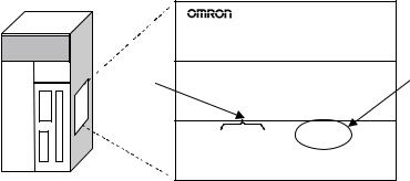
Notation of Unit Versions on Products
CS/CJ-series CPU Unit
The unit version is given to the right of the lot number on the nameplate of the products for which unit versions are being managed, as shown below.
Product nameplate
CS1H-CPU67H |
|
CPU UNIT |
|
Lot No. |
Unit version |
|
Example for Unit version 3.0 |
Lot No. 040715 0000 |
Ver.3.0 |
OMRON Corporation |
MADE IN JAPAN |
Confirming Unit Versions with Support Software
•CS1-H, CJ1-H, and CJ1M CPU Units manufactured on or before November 4, 2003 do not have a unit version given on the CPU Unit (i.e., the location for the unit version shown above is blank).
•The unit version of the CJ1-H-R CPU Units begins at version 4.0.
•The unit version of the CS1-H, CJ1-H, and CJ1M CPU Units, as well as the CS1D CPU Units for Single-CPU Systems, begins at version 2.0.
•The unit version of the CS1D CPU Units for Duplex-CPU Systems, begins at version 1.1.
•CPU Units for which a unit version is not given are called Pre-Ver. @.@
CPU Units, such as Pre-Ver. 2.0 CPU Units and Pre-Ver. 1.1 CPU Units.
CX-Programmer version 4.0 can be used to confirm the unit version using one of the following two methods.
•Using the PLC Information
•Using the Unit Manufacturing Information (This method can be used for Special I/O Units and CPU Bus Units as well.)
Note CX-Programmer version 3.3 or lower cannot be used to confirm unit versions.
PLC Information
•If you know the device type and CPU type, select them in the Change PLC Dialog Box, go online, and select PLC - Edit - Information from the menus.
•If you don't know the device type and CPU type, but are connected directly to the CPU Unit on a serial line, select PLC - Auto Online to go online, and then select PLC - Edit - Information from the menus.
In either case, the following PLC Information Dialog Box will be displayed.
vi

Unit version
Use the above display to confirm the unit version of the CPU Unit.
Unit Manufacturing Information
In the IO Table Window, right-click and select Unit Manufacturing information - CPU Unit.
The following Unit Manufacturing information Dialog Box will be displayed.
vii
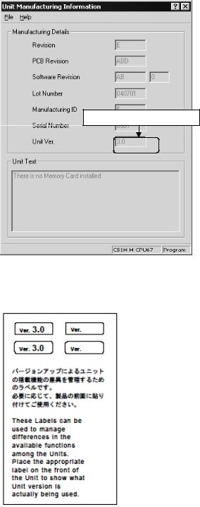
Unit version
|
Use the above display to confirm the unit version of the CPU Unit connected |
|
online. |
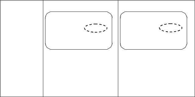
Using the Unit Version |
The following unit version labels are provided with the CPU Unit. |
Labels |
|
These labels can be attached to the front of previous CPU Units to differentiate between CPU Units of different unit versions.
viii
Unit Version Notation In this manual, the unit version of a CPU Unit is given as shown in the following table.
Product nameplate CPU Units on which no unit version is |
Units on which a version is given |
given |
(Ver. @.@) |
|
Lot No. XXXXXX XXXX |
Lot No. XXXXXX XXXX |
Ver. @ .@ |
|
|
OMRON Corporation MADE IN JAPAN |
|
|
|
Meaning |
|
|
|
|
|
|
|
|
|
Designating individual |
Pre-Ver. 2.0 |
CS1-H CPU Units |
CS1H-CPU67H CPU Unit Ver. @.@ |
|
CPU Units (e.g., the |
|
|
|
|
CS1H-CPU67H) |
|
|
|
|
|
|
|
|
|
Designating groups of |
Pre-Ver. 2.0 |
CS1-H CPU Units |
CS1-H CPU Units Ver. @.@ |
|
CPU Units (e.g., the |
|
|
|
|
CS1-H CPU Units) |
|
|
|
|
|
|
|
|
|
Designating an entire |
Pre-Ver. 2.0 |
CS-series CPU Units |
CS-series CPU Units Ver. @.@ |
|
series of CPU Units |
|
|
|
|
(e.g., the CS-series CPU |
|
|
|
|
Units) |
|
|
|
|
ix
Unit Versions
CS Series
Units |
Models |
Unit version |
|
|
|
CS1-H CPU Units |
CS1@-CPU@@H |
Unit version 4.1 |
|
|
Unit version 4.0 |
|
|
|
|
|
Unit version 3.0 |
|
|
|
|
|
Unit version 2.0 |
|
|
|
|
|
Pre-Ver. 2.0 |
|
|
|
CS1D CPU Units |
Duplex-CPU Systems |
Unit version 1.2 |
|
CS1D-CPU@@H |
|
|
Unit version 1.1 |
|
|
|
|
|
|
|
|
|
Pre-Ver. 1.1 |
|
|
|
|
Single-CPU Systems |
Unit version 2.0 |
|
CS1D-CPU@@S |
|
CS1 CPU Units |
CS1@-CPU@@ |
No unit version. |
CS1 Version-1 CPU Units |
CS1@-CPU@@-V1 |
No unit version. |
|
|
|
CJ Series
Units |
Models |
Unit version |
|
|
|
CJ1-H CPU Units |
CJ1H-CPU@@H-R |
Unit version 4.2 |
|
|
Unit version 4.1 |
|
|
|
|
|
Unit version 4.0 |
|
|
|
|
CJ1@-CPU@@H |
Unit version 4.0 |
|
CJ1@-CPU@@P |
Unit version 3.0 |
|
|
|
|
|
Unit version 2.0 |
|
|
|
|
|
Pre-Ver. 2.0 |
|
|
|
CJ1M CPU Units |
CJ1M-CPU12/13 |
Unit version 4.0 |
|
CJ1M-CPU22/23 |
Unit version 3.0 |
|
|
|
|
|
Unit version 2.0 |
|
|
|
|
|
Pre-Ver. 2.0 |
|
|
|
|
CJ1M-CPU11/21 |
Unit version 4.0 |
|
|
|
|
|
Unit version 3.0 |
|
|
|
|
|
Unit version 2.0 |
|
|
|
NSJ Series
Units |
Unit version |
|
|
NSJ@-TQ@@(B)-G5D |
Unit version 3.0 |
NSJ@-TQ@@(B)-M3D |
|
x
Function Support by Unit Version
• Functions Supported for Unit Version 4.0 or Later
CX-Programmer 7.0 or higher must be used to enable using the functions added for unit version 4.0.
Additional functions are supported if CX-Programmer version 7.2 or higher is used.
CS1-H CPU Units
|
Function |
CS1@-CPU@@H |
|
|
|
Unit version 4.0 or later |
Other unit versions |
|
|
|
|
Online editing of function blocks |
OK |
--- |
|
Note This function cannot be used for simulations on the CX-Simulator. |
|
|
|
|
|
|
|
Input-output variables in function blocks |
OK |
--- |
|
|
|
|
|
Text strings in function blocks |
OK |
--- |
|
|
|
|
|
New application |
Number-Text String Conversion Instructions: |
OK |
--- |
instructions |
NUM4, NUM8, NUM16, STR4, STR8, and STR16 |
|
|
|
|
|
|
|
TEXT FILE WRITE (TWRIT) |
OK |
--- |
|
|
|
|
ST programming in task programs |
OK with CX-Program- |
--- |
|
|
|
mer version 7.2 or higher |
|
|
|
|
|
SFC programming in task programs |
OK with CX-Program- |
--- |
|
|
|
mer version 7.2 or higher |
|
|
|
|
|
CS1D CPU Units |
Unit version 4.0 is not supported. |
|
|
|
CJ1-H/CJ1M CPU Units |
|
|
|
|
|
|
|
|
|
|
Function |
CJ1H-CPU@@H-R, CJ1@-CPU@@H, |
||
|
|
|
CJ1G-CPU@@P, CJ1M-CPU@@ |
|
|
|
|
Unit version 4.0 or later |
Other unit versions |
|
|
|
|
|
Online editing of function blocks |
|
OK |
--- |
|
Note This function cannot be used for simulations on the CX-Simulator. |
|
|
||
|
|
|
||
Input-output variables in function blocks |
OK |
--- |
||
|
|
|
|
|
Text strings in function blocks |
|
OK |
--- |
|
|
|
|
|
|
New application |
Number-Text String Conversion Instructions: |
OK |
--- |
|
instructions |
NUM4, NUM8, NUM16, STR4, STR8, and STR16 |
|
|
|
|
|
|
|
|
|
TEXT FILE WRITE (TWRIT) |
OK |
--- |
|
|
|
|
|
|
ST programming in task programs |
|
OK with CX-Program- |
--- |
|
|
|
|
mer version 7.2 or higher |
|
|
|
|
||
SFC programming in task programs |
OK with CX-Program- |
--- |
||
|
|
|
mer version 7.2 or higher |
|
User programs that contain functions supported only by CPU Units with unit version 4.0 or later cannot be used on CS/CJ-series CPU Units with unit version 3.0 or earlier. An error message will be displayed if an attempt is made to download programs containing unit version 4.0 functions to a CPU Unit with a unit version of 3.0 or earlier, and the download will not be possible.
If an object program file (.OBJ) using these functions is transferred to a CPU Unit with a unit version of 3.0 or earlier, a program error will occur when operation is started or when the unit version 4.0 function is executed, and CPU Unit operation will stop.
xi
• Functions Supported for Unit Version 3.0 or Later
CX-Programmer 5.0 or higher must be used to enable using the functions added for unit version 3.0.
CS1-H CPU Units
|
|
Function |
CS1@-CPU@@H |
||
|
|
|
|
Unit version 3.0 or |
Other unit versions |
|
|
|
|
later |
|
|
|
|
|
|
|
Function blocks |
|
|
|
OK |
--- |
|
|
|
|
||
Serial Gateway (converting FINS commands to CompoWay/F |
OK |
--- |
|||
commands at the built-in serial port) |
|
|
|||
|
|
|
|
||
Comment memory (in internal flash memory) |
OK |
--- |
|||
|
|
|
|
|
|
Expanded simple backup data |
|
OK |
--- |
||
|
|
|
|
|
|
New application |
|
TXDU(256), RXDU(255) (support no-protocol com- |
OK |
--- |
|
instructions |
|
munications with Serial Communications Units with |
|
|
|
|
|
unit version 1.2 or later) |
|
|
|
|
|
|
|
|
|
|
|
Model conversion instructions: XFERC(565), |
OK |
--- |
|
|
|
DISTC(566), COLLC(567), MOVBC(568), |
|
|
|
|
|
BCNTC(621) |
|
|
|
|
|
|
|
|
|
|
|
Special function block instructions: GETID(286) |
OK |
--- |
|
|
|
|
|
|
|
Additional |
|
TXD(235) and RXD(236) instructions (support no- |
OK |
--- |
|
instruction func- |
|
protocol communications with Serial Communica- |
|
|
|
tions |
|
tions Boards with unit version 1.2 or later) |
|
|
|
CS1D CPU Units |
Unit version 3.0 is not supported. |
|
|||
CJ1-H/CJ1M CPU Units |
|
|
|
||
|
|
|
|
||
|
|
Function |
CJ1H-CPU@@H-R, CJ1@-CPU@@H, |
||
|
|
|
|
CJ1G-CPU@@P, CJ1M-CPU@@ |
|
|
|
|
|
Unit version 3.0 or |
Other unit versions |
|
|
|
|
later |
|
|
|
|
|
|
|
Function blocks |
|
|
|
OK |
--- |
|
|
|
|||
Serial Gateway (converting FINS commands to CompoWay/F |
OK |
--- |
|||
commands at the built-in serial port) |
|
|
|||
|
|
|
|||
Comment memory (in internal flash memory) |
OK |
--- |
|||
|
|
|
|
||
Expanded simple backup data |
|
OK |
--- |
||
|
|
|
|
|
|
New application |
|
TXDU(256), RXDU(255) (support no-protocol com- |
OK |
--- |
|
instructions |
|
munications with Serial Communications Units with |
|
|
|
|
|
unit version 1.2 or later) |
|
|
|
|
|
|
|
|
|
|
|
Model conversion instructions: XFERC(565), |
OK |
--- |
|
|
|
DISTC(566), COLLC(567), MOVBC(568), |
|
|
|
|
|
BCNTC(621) |
|
|
|
|
|
|
|
|
|
|
|
Special function block instructions: GETID(286) |
OK |
--- |
|
|
|
|
|
|
|
Additional |
|
PRV(881) and PRV2(883) instructions: Added high- |
OK |
--- |
|
instruction func- |
frequency calculation methods for calculating pulse |
|
|
||
tions |
|
frequency. (CJ1M CPU Units only) |
|
|
|
|
|
|
|
|
|
User programs that contain functions supported only by CPU Units with unit version 3.0 or later cannot be used on CS/CJ-series CPU Units with unit version 2.0 or earlier. An error message will be displayed if an attempt is made to download programs containing unit version 3.0 functions to a CPU Unit with a unit version of 2.0 or earlier, and the download will not be possible.
If an object program file (.OBJ) using these functions is transferred to a CPU Unit with a unit version of 2.0 or earlier, a program error will occur when operation is started or when the unit version 3.0 function is executed, and CPU Unit operation will stop.
xii
• Functions Supported for Unit Version 2.0 or Later
CX-Programmer 4.0 or higher must be used to enable using the functions added for unit version 2.0.
CS1-H CPU Units
|
Function |
CS1-H CPU Units |
||
|
|
(CS1@-CPU@@H) |
||
|
|
|
|
|
|
|
Unit version 2.0 or later |
Other unit versions |
|
|
|
|
||
Downloading and Uploading Individual Tasks |
OK |
--- |
||
|
|
|
||
Improved Read Protection Using Passwords |
OK |
--- |
||
|
|
|
||
Write Protection from FINS Commands Sent to CPU |
OK |
--- |
||
Units via Networks |
|
|
|
|
|
|
|
||
Online Network Connections without I/O Tables |
OK |
--- |
||
|
|
|
||
Communications through a Maximum of 8 Network Lev- |
OK |
--- |
||
els |
|
|
|
|
|
|
|
||
Connecting Online to PLCs via NS-series PTs |
OK |
OK from lot number 030201 |
||
|
|
|
||
Setting First Slot Words |
OK for up to 64 groups |
OK for up to 8 groups |
||
|
|
|
||
Automatic Transfers at Power ON without a Parameter |
OK |
--- |
||
File |
|
|
|
|
|
|
|
||
Automatic Detection of I/O Allocation Method for Auto- |
--- |
--- |
||
matic Transfer at Power ON |
|
|
||
|
|
|
||
Operation Start/End Times |
OK |
--- |
||
|
|
|
|
|
New Application |
MILH, MILR, MILC |
OK |
--- |
|
Instructions |
|
|
|
|
=DT, <>DT, <DT, <=DT, >DT, >=DT |
OK |
--- |
||
|
||||
|
|
|
|
|
|
BCMP2 |
OK |
--- |
|
|
|
|
|
|
|
GRY |
OK |
OK from lot number 030201 |
|
|
|
|
|
|
|
TPO |
OK |
--- |
|
|
|
|
|
|
|
DSW, TKY, HKY, MTR, 7SEG |
OK |
--- |
|
|
|
|
|
|
|
EXPLT, EGATR, ESATR, ECHRD, |
OK |
--- |
|
|
ECHWR |
|
|
|
|
|
|
|
|
|
Reading/Writing CPU Bus Units |
OK |
OK from lot number 030418 |
|
|
with IORD/IOWR |
|
|
|
|
|
|
|
|
|
PRV2 |
--- |
--- |
|
|
|
|
|
|
xiii
CS1D CPU Units
|
Function |
CS1D CPU Units for |
CS1D CPU Units for Duplex-CPU |
||
|
|
Single-CPU Systems |
Systems (CS1D-CPU@@H) |
||
|
|
(CS1D-CPU@@S) |
|
|
|
|
|
Unit version 2.0 |
Unit version 1.1 or |
Pre-Ver. 1.1 |
|
|
|
|
later |
|
|
|
|
|
|
|
|
Functions |
Duplex CPU Units |
--- |
OK |
OK |
|
unique to CS1D |
|
|
|
|
|
Online Unit Replacement |
OK |
OK |
OK |
||
CPU Units |
|
|
|
|
|
Duplex Power Supply Units |
OK |
OK |
OK |
||
|
|||||
|
|
|
|
|
|
|
Duplex Controller Link |
OK |
OK |
OK |
|
|
Units |
|
|
|
|
|
|
|
|
|
|
|
Duplex Ethernet Units |
--- |
OK |
OK |
|
|
|
|
|
|
|
|
Unit removal without a |
--- |
OK (Unit version 1.2 or |
--- |
|
|
Programming Device |
|
later) |
|
|
|
|
|
|
|
|
Downloading and Uploading Individual Tasks |
OK |
--- |
--- |
||
|
|
|
|
||
Improved Read Protection Using Passwords |
OK |
--- |
--- |
||
|
|
|
|
||
Write Protection from FINS Commands Sent |
OK |
--- |
--- |
||
to CPU Units via Networks |
|
|
|
||
|
|
|
|
||
Online Network Connections without I/O |
OK |
--- |
--- |
||
Tables |
|
|
|
|
|
|
|
|
|
||
Communications through a Maximum of 8 |
OK |
--- |
--- |
||
Network Levels |
|
|
|
|
|
|
|
|
|
||
Connecting Online to PLCs via NS-series |
OK |
--- |
--- |
||
PTs |
|
|
|
|
|
|
|
|
|
||
Setting First Slot Words |
OK for up to 64 groups |
--- |
--- |
||
|
|
|
|
||
Automatic Transfers at Power ON without a |
OK |
--- |
--- |
||
Parameter File |
|
|
|
|
|
|
|
|
|
||
Automatic Detection of I/O Allocation Method |
--- |
--- |
--- |
||
for Automatic Transfer at Power ON |
|
|
|
||
|
|
|
|
||
Operation Start/End Times |
OK |
OK |
--- |
||
|
|
|
|
|
|
New Applica- |
MILH, MILR, MILC |
OK |
--- |
--- |
|
tion Instructions |
|
|
|
|
|
=DT, <>DT, <DT, <=DT, |
OK |
--- |
--- |
||
|
>DT, >=DT |
|
|
|
|
|
|
|
|
|
|
|
BCMP2 |
OK |
--- |
--- |
|
|
|
|
|
|
|
|
GRY |
OK |
--- |
--- |
|
|
|
|
|
|
|
|
TPO |
OK |
--- |
--- |
|
|
|
|
|
|
|
|
DSW, TKY, HKY, MTR, |
OK |
--- |
--- |
|
|
7SEG |
|
|
|
|
|
|
|
|
|
|
|
EXPLT, EGATR, ESATR, |
OK |
--- |
--- |
|
|
ECHRD, ECHWR |
|
|
|
|
|
|
|
|
|
|
|
Reading/Writing CPU Bus |
OK |
--- |
--- |
|
|
Units with IORD/IOWR |
|
|
|
|
|
|
|
|
|
|
|
PRV2 |
OK |
--- |
--- |
|
|
|
|
|
|
|
xiv
CJ1-H/CJ1M CPU Units
|
|
Function |
CJ1-H CPU Units |
CJ1M CPU Units |
|||
|
|
|
(CJ1@-CPU@@H) |
||||
|
|
|
|
|
|
||
|
|
|
|
|
|
||
|
|
|
(CJ1H-CPU@@H-R) |
CJ1M-CPU12/13/22/23 |
CJ1M- |
||
|
|
|
(CJ1@-CPU@@H) |
|
|
CPU11/21 |
|
|
|
|
(CJ1G-CPU@@P) |
|
|
|
|
|
|
|
Unit version |
Other unit |
Unit version |
Other unit |
Other unit |
|
|
|
2.0 or later |
versions |
2.0 or later |
versions |
versions |
Downloading and Uploading Individual Tasks |
OK |
--- |
OK |
--- |
OK |
||
|
|
|
|
|
|
||
Improved Read Protection Using Passwords |
OK |
--- |
OK |
--- |
OK |
||
|
|
|
|
|
|
||
Write Protection from FINS Commands Sent |
OK |
--- |
OK |
--- |
OK |
||
to CPU Units via Networks |
|
|
|
|
|
||
|
|
|
|
|
|
||
Online Network Connections without I/O |
OK |
--- |
OK |
--- |
OK |
||
Tables |
|
|
(Supported if |
|
(Supported if |
|
|
|
|
|
|
I/O tables are |
|
I/O tables are |
|
|
|
|
|
automatically |
|
automatically |
|
|
|
|
|
generated at |
|
generated at |
|
|
|
|
|
startup.) |
|
startup.) |
|
|
|
|
|
|
|
||
Communications through a Maximum of 8 |
OK |
--- |
OK |
--- |
OK |
||
Network Levels |
|
|
|
|
|
|
|
|
|
|
|
|
|
||
Connecting Online to PLCs via NS-series |
OK |
OK from lot |
OK |
OK from lot |
OK |
||
PTs |
|
|
number |
|
number |
|
|
|
|
|
|
030201 |
|
030201 |
|
|
|
|
|
|
|
||
Setting First Slot Words |
OK for up to |
OK for up to |
OK for up to |
OK for up to |
OK for up to |
||
|
|
|
64 groups |
8 groups |
64 groups |
8 groups |
64 groups |
|
|
|
|
|
|
||
Automatic Transfers at Power ON without a |
OK |
--- |
OK |
--- |
OK |
||
Parameter File |
|
|
|
|
|
|
|
|
|
|
|
|
|
||
Automatic Detection of I/O Allocation Method |
--- |
--- |
--- |
--- |
--- |
||
for Automatic Transfer at Power ON |
|
|
|
|
|
||
|
|
|
|
|
|
||
Operation Start/End Times |
OK |
--- |
OK |
--- |
OK |
||
|
|
|
|
|
|
||
New Applica- |
MILH, MILR, MILC |
OK |
--- |
OK |
--- |
OK |
|
tion Instruc- |
|
|
|
|
|
|
|
|
=DT, <>DT, <DT, <=DT, >DT, |
OK |
--- |
OK |
--- |
OK |
|
tions |
|
||||||
|
>=DT |
|
|
|
|
|
|
|
|
|
|
|
|
|
|
|
|
|
|
|
|
|
|
|
|
BCMP2 |
OK |
--- |
OK |
OK |
OK |
|
|
|
|
|
|
|
|
|
|
GRY |
OK |
OK from lot |
OK |
OK from lot |
OK |
|
|
|
|
number |
|
number |
|
|
|
|
|
030201 |
|
030201 |
|
|
|
|
|
|
|
|
|
|
|
TPO |
OK |
--- |
OK |
--- |
OK |
|
|
|
|
|
|
|
|
|
|
DSW, TKY, HKY, MTR, 7SEG |
OK |
--- |
OK |
--- |
OK |
|
|
|
|
|
|
|
|
|
|
EXPLT, EGATR, ESATR, |
OK |
--- |
OK |
--- |
OK |
|
|
ECHRD, ECHWR |
|
|
|
|
|
|
|
|
|
|
|
|
|
|
|
Reading/Writing CPU Bus |
OK |
--- |
OK |
--- |
OK |
|
|
Units with IORD/IOWR |
|
|
|
|
|
|
|
|
|
|
|
|
|
|
|
PRV2 |
--- |
--- |
OK, but only |
--- |
OK, but only |
|
|
|
|
|
for CPU Units |
|
for CPU Units |
|
|
|
|
|
with built-in |
|
with built-in |
|
|
|
|
|
I/O |
|
I/O |
|
|
|
|
|
|
|
|
User programs that contain functions supported only by CPU Units with unit version 2.0 or later cannot be used on CS/CJ-series Pre-Ver. 2.0 CPU Units. An error message will be displayed if an attempt is made to download programs containing unit version s.0 functions to a Pre-Ver. 2.0 CPU Unit, and the download will not be possible.
If an object program file (.OBJ) using these functions is transferred to a PreVer. 2.0 CPU Unit, a program error will occur when operation is started or when the unit version 2.0 function is executed, and CPU Unit operation will stop.
xv
Unit Versions and Programming Devices
The following tables show the relationship between unit versions and CX-Pro- grammer versions.
Unit Versions and Programming Devices
CPU Unit |
Functions (See note 1.) |
|
CX-Programmer |
|
Program- |
||
|
|
|
|
|
|
|
ming |
|
|
|
Ver. 3.3 |
Ver. 4.0 |
Ver. 5.0 |
Ver. 7.0 |
|
|
|
|
Console |
||||
|
|
|
or lower |
|
Ver. 6.0 |
or higher |
|
|
|
|
|
|
|||
|
|
|
|
|
|
|
|
CS/CJ-series unit |
Functions added |
Using new functions |
--- |
--- |
--- |
OK (See |
No |
Ver. 4.0 |
for unit version 4.0 |
|
|
|
|
notes 2 |
restric- |
|
|
|
|
|
|
and 3.) |
tions |
|
|
|
|
|
|
|
|
|
|
Not using new functions |
OK |
OK |
OK |
OK |
|
|
|
|
|
|
|
|
|
CS/CJ-series unit |
Functions added |
Using new functions |
--- |
--- |
OK |
OK |
|
Ver. 3.0 |
for unit version 3.0 |
|
|
|
|
|
|
Not using new functions |
OK |
OK |
OK |
OK |
|
||
|
|
|
|
|
|
|
|
CS/CJ-series unit |
Functions added |
Using new functions |
--- |
OK |
OK |
OK |
|
Ver. 2.0 |
for unit version 2.0 |
|
|
|
|
|
|
Not using new functions |
OK |
OK |
OK |
OK |
|
||
|
|
|
|
|
|
|
|
CS1D CPU Units |
Functions added |
Using new functions |
--- |
OK |
OK |
OK |
|
for Single-CPU Sys- |
for unit version 2.0 |
|
|
|
|
|
|
Not using new functions |
|
|
|
|
|
||
tems, unit Ver. 2.0 |
|
|
|
|
|
|
|
CS1D CPU Units |
Functions added |
Using function blocks |
--- |
OK |
OK |
OK |
|
for Duplex-CPU |
for unit version 1.1 |
|
|
|
|
|
|
Not using function blocks |
OK |
OK |
OK |
OK |
|
||
Systems, unit Ver.1. |
|
|
|
|
|
|
|
Note 1. As shown above, there is no need to upgrade to CX-Programmer version as long as the functions added for unit versions are not used.
2.CX-Programmer version 7.1 or higher is required to use the new functions added for unit version 4.0 of the CJ1-H-R CPU Units. CX-Programmer version 7.22 or higher is required to use unit version 4.1 of the CJ1-H-R CPU Units. CX-Programmer version 7.0 or higher is required to use unit version 4.2 of the CJ1-H-R CPU Units. You can check the CX-Programmer version using the About menu command to display version information.
3.CX-Programmer version 7.0 or higher is required to use the functional improvements made for unit version 4.0 of the CS/CJ-series CPU Units. With CX-Programmer version 7.2 or higher, you can use even more expanded functionality.
Device Type Setting |
The unit version does not affect the setting made for the device type on the |
|||
|
|
CX-Programmer. Select the device type as shown in the following table |
||
|
|
regardless of the unit version of the CPU Unit. |
||
|
|
|
|
|
Series |
CPU Unit group |
CPU Unit model |
Device type setting on |
|
|
|
|
|
CX-Programmer Ver. 4.0 or higher |
|
|
|
|
|
CS Series |
CS1-H CPU Units |
|
CS1G-CPU@@H |
CS1G-H |
|
|
|
CS1H-CPU@@H |
CS1H-H |
|
CS1D CPU Units for Duplex-CPU Systems |
CS1D-CPU@@H |
CS1D-H (or CS1H-H) |
|
|
CS1D CPU Units for Single-CPU Systems |
CS1D-CPU@@S |
CS1D-S |
|
CJ Series |
CJ1-H CPU Units |
|
CJ1G-CPU@@H |
CJ1G-H |
|
|
|
CJ1G-CPU@@P |
|
|
|
|
CJ1H-CPU@@H-R |
CJ1H-H |
|
|
|
(See note.) |
|
|
|
|
CJ1H-CPU@@H |
|
|
CJ1M CPU Units |
|
CJ1M-CPU@@ |
CJ1M |
Note When using a CJ1H-CPU@@H-R CPU Unit, set the CPU Unit model to CPU67-R, CPU66-R, CPU65-R, or CPU64-R.
xvi
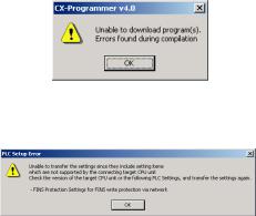
Troubleshooting Problems with Unit Versions on the CX-Programmer
Problem |
Cause |
Solution |
|
|
|
|
An attempt was made to down- |
Check the program or change |
|
load a program containing |
to a CPU Unit with a later unit |
|
instructions supported only by |
version. |
|
later unit versions or a CPU Unit |
|
|
to a previous unit version. |
|
After the above message is displayed, a compiling |
|
|
error will be displayed on the Compile Tab Page in the |
|
|
Output Window. |
|
|
|
|
|
|
An attempt was to download a |
Check the settings in the PLC |
|
PLC Setup containing settings |
Setup or change to a CPU Unit |
|
supported only by later unit ver- |
with a later unit version. |
|
sions or a CPU Unit to a previous |
|
|
unit version. |
|
|
|
|
“????” is displayed in a program transferred from the |
An attempt was made to upload a |
New instructions cannot be |
PLC to the CX-Programmer. |
program containing instructions |
uploaded to lower versions of |
|
supported only by higher versions |
CX-Programmer. Use a higher |
|
of CX-Programmer to a lower |
version of CX-Programmer. |
|
version. |
|
|
|
|
xvii
xviii
TABLE OF CONTENTS
PRECAUTIONS . . . . . . . . . . . . . . . . . . . . . . . . . . . . . . . . . . . |
xxv |
|
1 |
Intended Audience . . . . . . . . . . . . . . . . . . . . . . . . . . . . . . . . . . . . . . . . . . . . . . . . . . . . . . . . |
xxvi |
2 |
General Precautions . . . . . . . . . . . . . . . . . . . . . . . . . . . . . . . . . . . . . . . . . . . . . . . . . . . . . . . |
xxvi |
3 |
Safety Precautions. . . . . . . . . . . . . . . . . . . . . . . . . . . . . . . . . . . . . . . . . . . . . . . . . . . . . . . . . |
xxvi |
4 |
Operating Environment Precautions . . . . . . . . . . . . . . . . . . . . . . . . . . . . . . . . . . . . . . . . . . . |
xxviii |
5 |
Application Precautions . . . . . . . . . . . . . . . . . . . . . . . . . . . . . . . . . . . . . . . . . . . . . . . . . . . . |
xxix |
6 |
Conformance to EC Directives . . . . . . . . . . . . . . . . . . . . . . . . . . . . . . . . . . . . . . . . . . . . . . . |
xxxii |
SECTION 1 |
|
|
CPU Unit Operation. . . . . . . . . . . . . . . . . . . . . . . . . . . . . . . . |
1 |
|
1-1 |
Initial Setup (CS1 CPU Units Only) . . . . . . . . . . . . . . . . . . . . . . . . . . . . . . . . . . . . . . . . . . . |
2 |
1-2 |
Using the Internal Clock (CS1 CPU Units Only) . . . . . . . . . . . . . . . . . . . . . . . . . . . . . . . . . |
5 |
1-3 |
Internal Structure of the CPU Unit . . . . . . . . . . . . . . . . . . . . . . . . . . . . . . . . . . . . . . . . . . . . |
6 |
1-4 |
Operating Modes. . . . . . . . . . . . . . . . . . . . . . . . . . . . . . . . . . . . . . . . . . . . . . . . . . . . . . . . . . |
9 |
1-5 |
Programs and Tasks. . . . . . . . . . . . . . . . . . . . . . . . . . . . . . . . . . . . . . . . . . . . . . . . . . . . . . . . |
13 |
1-6 |
Description of Tasks . . . . . . . . . . . . . . . . . . . . . . . . . . . . . . . . . . . . . . . . . . . . . . . . . . . . . . . |
15 |
SECTION 2 |
|
|
Programming . . . . . . . . . . . . . . . . . . . . . . . . . . . . . . . . . . . . . |
21 |
|
2-1 |
Basic Concepts . . . . . . . . . . . . . . . . . . . . . . . . . . . . . . . . . . . . . . . . . . . . . . . . . . . . . . . . . . . |
22 |
2-2 |
Precautions . . . . . . . . . . . . . . . . . . . . . . . . . . . . . . . . . . . . . . . . . . . . . . . . . . . . . . . . . . . . . . |
58 |
2-3 |
Checking Programs . . . . . . . . . . . . . . . . . . . . . . . . . . . . . . . . . . . . . . . . . . . . . . . . . . . . . . . . |
67 |
SECTION 3 |
|
|
Instruction Functions . . . . . . . . . . . . . . . . . . . . . . . . . . . . . . . |
73 |
|
3-1 |
Sequence Input Instructions . . . . . . . . . . . . . . . . . . . . . . . . . . . . . . . . . . . . . . . . . . . . . . . . . |
74 |
3-2 |
Sequence Output Instructions . . . . . . . . . . . . . . . . . . . . . . . . . . . . . . . . . . . . . . . . . . . . . . . . |
76 |
3-3 |
Sequence Control Instructions . . . . . . . . . . . . . . . . . . . . . . . . . . . . . . . . . . . . . . . . . . . . . . . |
79 |
3-4 |
Timer and Counter Instructions . . . . . . . . . . . . . . . . . . . . . . . . . . . . . . . . . . . . . . . . . . . . . . |
83 |
3-5 |
Comparison Instructions . . . . . . . . . . . . . . . . . . . . . . . . . . . . . . . . . . . . . . . . . . . . . . . . . . . . |
88 |
3-6 |
Data Movement Instructions . . . . . . . . . . . . . . . . . . . . . . . . . . . . . . . . . . . . . . . . . . . . . . . . . |
92 |
3-7 |
Data Shift Instructions . . . . . . . . . . . . . . . . . . . . . . . . . . . . . . . . . . . . . . . . . . . . . . . . . . . . . |
95 |
3-8 |
Increment/Decrement Instructions . . . . . . . . . . . . . . . . . . . . . . . . . . . . . . . . . . . . . . . . . . . . |
99 |
3-9 |
Symbol Math Instructions. . . . . . . . . . . . . . . . . . . . . . . . . . . . . . . . . . . . . . . . . . . . . . . . . . . |
100 |
3-10 |
Conversion Instructions. . . . . . . . . . . . . . . . . . . . . . . . . . . . . . . . . . . . . . . . . . . . . . . . . . . . . |
105 |
3-11 |
Logic Instructions . . . . . . . . . . . . . . . . . . . . . . . . . . . . . . . . . . . . . . . . . . . . . . . . . . . . . . . . . |
112 |
3-12 |
Special Math Instructions . . . . . . . . . . . . . . . . . . . . . . . . . . . . . . . . . . . . . . . . . . . . . . . . . . . |
114 |
3-13 |
Floating-point Math Instructions . . . . . . . . . . . . . . . . . . . . . . . . . . . . . . . . . . . . . . . . . . . . . |
115 |
3-14 |
Double-precision Floating-point Instructions . . . . . . . . . . . . . . . . . . . . . . . . . . . . . . . . . . . . |
121 |
3-15 |
Table Data Processing Instructions . . . . . . . . . . . . . . . . . . . . . . . . . . . . . . . . . . . . . . . . . . . . |
125 |
3-16 |
Data Control Instructions . . . . . . . . . . . . . . . . . . . . . . . . . . . . . . . . . . . . . . . . . . . . . . . . . . . |
129 |
3-17 |
Subroutine Instructions . . . . . . . . . . . . . . . . . . . . . . . . . . . . . . . . . . . . . . . . . . . . . . . . . . . . . |
133 |
3-18 |
Interrupt Control Instructions . . . . . . . . . . . . . . . . . . . . . . . . . . . . . . . . . . . . . . . . . . . . . . . . |
134 |
3-19 |
High-speed Counter and Pulse Output Instructions (CJ1M-CPU21/22/23 Only) . . . . . . . . |
136 |
3-20 |
Step Instructions . . . . . . . . . . . . . . . . . . . . . . . . . . . . . . . . . . . . . . . . . . . . . . . . . . . . . . . . . . |
138 |
3-21 |
Basic I/O Unit Instructions . . . . . . . . . . . . . . . . . . . . . . . . . . . . . . . . . . . . . . . . . . . . . . . . . . |
138 |
3-22 |
Serial Communications Instructions . . . . . . . . . . . . . . . . . . . . . . . . . . . . . . . . . . . . . . . . . . . |
142 |
3-23 |
Network Instructions. . . . . . . . . . . . . . . . . . . . . . . . . . . . . . . . . . . . . . . . . . . . . . . . . . . . . . . |
143 |
3-24 |
File Memory Instructions . . . . . . . . . . . . . . . . . . . . . . . . . . . . . . . . . . . . . . . . . . . . . . . . . . . |
145 |
3-25 |
Display Instructions . . . . . . . . . . . . . . . . . . . . . . . . . . . . . . . . . . . . . . . . . . . . . . . . . . . . . . . |
147 |
3-26 |
Clock Instructions . . . . . . . . . . . . . . . . . . . . . . . . . . . . . . . . . . . . . . . . . . . . . . . . . . . . . . . . . |
147 |
xix
TABLE OF CONTENTS
3-27 |
Debugging Instructions . . . . . . . . . . . . . . . . . . . . . . . . . . . . . . . . . . . . . . . . . . . . . . . . . . . . . |
148 |
3-28 |
Failure Diagnosis Instructions. . . . . . . . . . . . . . . . . . . . . . . . . . . . . . . . . . . . . . . . . . . . . . . . |
149 |
3-29 |
Other Instructions . . . . . . . . . . . . . . . . . . . . . . . . . . . . . . . . . . . . . . . . . . . . . . . . . . . . . . . . . |
150 |
3-30 |
Block Programming Instructions . . . . . . . . . . . . . . . . . . . . . . . . . . . . . . . . . . . . . . . . . . . . . |
151 |
3-31 Text String Processing Instructions. . . . . . . . . . . . . . . . . . . . . . . . . . . . . . . . . . . . . . . . . . . . |
157 |
|
3-32 |
Task Control Instructions . . . . . . . . . . . . . . . . . . . . . . . . . . . . . . . . . . . . . . . . . . . . . . . . . . . |
160 |
3-33 Model Conversion Instructions (CPU Unit Ver. 3.0 or Later Only) . . . . . . . . . . . . . . . . . . . |
161 |
|
3-34 Special Function Block Instructions . . . . . . . . . . . . . . . . . . . . . . . . . . . . . . . . . . . . . . . . . . . |
162 |
|
SECTION 4 |
|
|
Tasks . . . . . . . . . . . . . . . . . . . . . . . . . . . . . . . . . . . . . . . . . . . . |
163 |
|
4-1 |
Task Features. . . . . . . . . . . . . . . . . . . . . . . . . . . . . . . . . . . . . . . . . . . . . . . . . . . . . . . . . . . . . |
164 |
4-2 |
Using Tasks . . . . . . . . . . . . . . . . . . . . . . . . . . . . . . . . . . . . . . . . . . . . . . . . . . . . . . . . . . . . . . |
173 |
4-3 |
Interrupt Tasks. . . . . . . . . . . . . . . . . . . . . . . . . . . . . . . . . . . . . . . . . . . . . . . . . . . . . . . . . . . . |
183 |
4-4 |
Programming Device Operations for Tasks . . . . . . . . . . . . . . . . . . . . . . . . . . . . . . . . . . . . . |
197 |
SECTION 5 |
|
|
File Memory Functions . . . . . . . . . . . . . . . . . . . . . . . . . . . . . |
199 |
|
5-1 |
File Memory . . . . . . . . . . . . . . . . . . . . . . . . . . . . . . . . . . . . . . . . . . . . . . . . . . . . . . . . . . . . . |
200 |
5-2 |
Manipulating Files . . . . . . . . . . . . . . . . . . . . . . . . . . . . . . . . . . . . . . . . . . . . . . . . . . . . . . . . |
219 |
5-3 |
Using File Memory . . . . . . . . . . . . . . . . . . . . . . . . . . . . . . . . . . . . . . . . . . . . . . . . . . . . . . . . |
253 |
SECTION 6 |
|
|
Advanced Functions . . . . . . . . . . . . . . . . . . . . . . . . . . . . . . . . |
261 |
|
6-1 |
Cycle Time/High-speed Processing . . . . . . . . . . . . . . . . . . . . . . . . . . . . . . . . . . . . . . . . . . . |
263 |
6-2 |
Index Registers . . . . . . . . . . . . . . . . . . . . . . . . . . . . . . . . . . . . . . . . . . . . . . . . . . . . . . . . . . . |
283 |
6-3 |
Serial Communications . . . . . . . . . . . . . . . . . . . . . . . . . . . . . . . . . . . . . . . . . . . . . . . . . . . . . |
293 |
6-4 |
Changing the Timer/Counter PV Refresh Mode. . . . . . . . . . . . . . . . . . . . . . . . . . . . . . . . . . |
313 |
6-5 |
Using a Scheduled Interrupt as a High-precision Timer (CJ1-H-R and CJ1M Only) . . . . . |
321 |
6-6 |
Startup Settings and Maintenance. . . . . . . . . . . . . . . . . . . . . . . . . . . . . . . . . . . . . . . . . . . . . |
323 |
6-7 |
Diagnostic Functions. . . . . . . . . . . . . . . . . . . . . . . . . . . . . . . . . . . . . . . . . . . . . . . . . . . . . . . |
337 |
6-8 |
CPU Processing Modes. . . . . . . . . . . . . . . . . . . . . . . . . . . . . . . . . . . . . . . . . . . . . . . . . . . . . |
343 |
6-9 |
Peripheral Servicing Priority Mode . . . . . . . . . . . . . . . . . . . . . . . . . . . . . . . . . . . . . . . . . . . |
348 |
6-10 |
Battery-free Operation . . . . . . . . . . . . . . . . . . . . . . . . . . . . . . . . . . . . . . . . . . . . . . . . . . . . . |
353 |
6-11 |
Other Functions. . . . . . . . . . . . . . . . . . . . . . . . . . . . . . . . . . . . . . . . . . . . . . . . . . . . . . . . . . . |
356 |
SECTION 7 |
|
|
Program Transfer, Trial Operation, and Debugging . . . . . |
359 |
|
7-1 |
Program Transfer. . . . . . . . . . . . . . . . . . . . . . . . . . . . . . . . . . . . . . . . . . . . . . . . . . . . . . . . . . |
360 |
7-2 |
Trial Operation and Debugging. . . . . . . . . . . . . . . . . . . . . . . . . . . . . . . . . . . . . . . . . . . . . . . |
361 |
Appendices |
|
|
A |
PLC Comparison Charts: CJ-series, CS-series, C200HG/HE/HX, CQM1H, CVM1, |
|
|
and CV-series PLCs . . . . . . . . . . . . . . . . . . . . . . . . . . . . . . . . . . . . . . . . . . . . . . . . . . . . . . . |
369 |
B |
Changes from Previous Host Link Systems . . . . . . . . . . . . . . . . . . . . . . . . . . . . . . . . . . . . . |
395 |
Index . . . . . . . . . . . . . . . . . . . . . . . . . . . . . . . . . . . . . . . . . . . . |
399 |
|
Revision History . . . . . . . . . . . . . . . . . . . . . . . . . . . . . . . . . . . |
405 |
|
xx
About this Manual:
This manual describes the programming of the CPU Units for CS/CJ-series Programmable Controllers (PLCs) and includes the sections described on the following page. The CS Series, CJ Series and NSJ Series are subdivided as shown in the following figure.
CS Series
CS1-H CPU Units
CS1H-CPU@@H
CS1G-CPU@@H
CS1D CPU Units
CS1D CPU Units for
Duplex Systems
CS1D-CPU@@H
CS1D CPU Units for
Simplex Systems
CS1D-CPU@@S
CS1D Process-control CPU Units
CS1D-CPU@@P
CS1 CPU Units
CS1H-CPU@@(-V1)
CS1G-CPU@@(-V1)
CS-series Basic I/O Units
CS-series Special I/O Units
CS-series CPU Bus Units
CS-series Power Supply Units
Note: A special Power Supply Unit must be used for CS1D CPU Units.
CJ Series
CJ2 CPU Units
CJ2H-CPU@@-@@@
CJ1-H CPU Units
CJ1H-CPU@@H-R CJ1H-CPU@@H CJ1G-CPU@@H CJ1G -CPU@@P
(Loop-control CPU Units)
CJ1M CPU Units
CJ1M-CPU@@
CJ1 CPU Units
CJ1G-CPU@@
CJ-series Basic I/O Units
CJ-series Special I/O Units
CJ-series CPU Bus Units
CJ-series Power Supply Units
NSJ Series
NSJ Controllers
NSJ5-TQ@@(B)-G5D NSJ5-SQ@@(B)-G5D NSJ8-TV@@(B)-G5D NSJ10-TV@@(B)-G5D NSJ12-TS@@(B)-G5D
NSJ Controllers
NSJ5-TQ@@(B)-M3D NSJ5-SQ@@(B)-M3D NSJ8-TV@@(B)-M3D
NSJ-series Expansion Units
Please read this manual and all related manuals listed in the table on the next page and be sure you understand information provided before attempting to install or use CS/CJ-series CPU Units in a PLC System.
NSJ-series Controller Notation
For information in this manual on the Controller Section of NSJ-series Controllers, refer to the information of the equivalent CJ-series PLC. The following models are equivalent.
NSJ-series Controllers |
Equivalent CJ-series CPU Unit |
NSJ@-TQ@@(B)-G5D |
CJ1G-CPU45H with unit version 3.0 |
NSJ@-TQ@@(B)-M3D |
CJ1G-CPU45H with unit version 3.0 (See note.) |
Note: The following points differ between the NSJ@-TQ@@(B)-M3D and the CJ1G-CPU45H.
|
Item |
CJ-series CPU Unit |
Controller Section in |
|
|
|
|
CJ1G-CPU45H |
NSJ@-@@@@(B)-M3D |
|
|
|
|
|
I/O capacity |
|
|
1280 points |
640 points |
|
|
|
|
|
Program capacity |
|
|
60 Ksteps |
20 Ksteps |
|
|
|
||
No. of Expansion Racks |
3 Racks max. |
1 Rack max. |
||
|
|
|
|
|
EM Area |
|
|
32 Kwords × 3 banks |
None |
|
|
|
E0_00000 - E2_32767 |
|
|
|
|
|
|
Function blocks |
|
Max. No. of definitions |
1024 |
128 |
|
|
|
|
|
|
|
Max. No. of instances |
2048 |
256 |
|
|
|
|
|
xxi
|
Item |
CJ-series CPU Unit |
Controller Section in |
|
|
|
|
CJ1G-CPU45H |
NSJ@-@@@@(B)-M3D |
|
|
|
|
|
Capacity in built-in |
|
FB program memory |
1024 KB |
256 KB |
|
|
|
|
|
file memory |
|
Variable tables |
128 KB |
64 KB |
|
|
|
|
|
This manual contains the following sections.
Precautions provides general precautions for using the CS/CJ-series Programmable Controllers (PLCs) and related devices.
Section 1 describes the basic structure and operation of the CPU Unit.
Section 2 describes basic information required to write, check, and input programs.
Section 3 outlines the instructions that can be used to write user programs.
Section 4 the operation of tasks.
Section 5 describes the functions used to manipulate file memory.
Section 6 provides details on the following advanced functions: cycle time/high-speed processing functions, index register functions, serial communications functions, startup and maintenance functions, diagnostic and debugging functions, Programming Device functions, and the Basic I/O Unit input response time settings.
Section 7 describes the processes used to transfer the program to the CPU Unit and the functions that can be used to test and debug the program.
The Appendices provide a comparison of CS/CJ-series, restrictions in using C200H Special I/O Units, and changes made to Host Link Systems.
xxii
About this Manual, Continued
Name |
Cat. No. |
Contents |
|
|
|
SYSMAC CS/CJ/NSJ Series |
W394 |
This manual describes programming and other |
CS1G/H-CPU@@-EV1, CS1G/H-CPU@@H, CS1D- |
(This |
methods to use the functions of the CS/CJ/NSJ- |
CPU@@H, CS1D-CPU@@S, CJ1H-CPU@@H-R, CJ1G- |
manual) |
series PLCs. |
CPU@@, CJ1G/H-CPU@@H, CJ1G-CPU@@P, CJ1M- |
|
|
CPU@@, NSJ@-@@@@(B)-G5D, NSJ@-@@@@(B)-M3D |
|
|
Programmable Controllers Programming Manual |
|
|
|
|
|
SYSMAC CS Series |
W339 |
Provides an outlines of and describes the design, |
CS1G/H-CPU@@-EV1, CS1G/H-CPU@@H |
|
installation, maintenance, and other basic opera- |
Programmable Controllers Operation Manual |
|
tions for the CS-series PLCs. |
|
|
|
SYSMAC CJ Series |
W393 |
Provides an outlines of and describes the design, |
CJ1H-CPU@@H-R, CJ1G/H-CPU@@H, CJ1G-CPU@@P, |
|
installation, maintenance, and other basic opera- |
CJ1G-CPU@@, CJ1M-CPU@@ |
|
tions for the CJ-series PLCs. |
Programmable Controllers Operation Manual |
|
|
|
|
|
SYSMAC CJ Series |
W395 |
Describes the functions of the built-in I/O for |
CJ1M-CPU21/22/23 |
|
CJ1M CPU Units. |
Built-in I/O Functions Operation Manual |
|
|
|
|
|
SYSMAC CS Series |
W405 |
Provides an outline of and describes the design, |
CS1D-CPU@@H CPU Units |
|
installation, maintenance, and other basic opera- |
CS1D-CPU@@S CPU Units |
|
tions for a Duplex System based on CS1D CPU |
CS1D-DPL1 Duplex Unit |
|
Units. |
CS1D-PA207R Power Supply Unit |
|
|
Duplex System Operation Manual |
|
|
|
|
|
SYSMAC CS/CJ/NSJ Series |
W340 |
Describes the ladder diagram programming |
CS1G/H-CPU@@-EV1, CS1G/H-CPU@@H, CS1D- |
|
instructions supported by CS/CJ-series PLCs. |
CPU@@H, CS1D-CPU@@S, CJ1H-CPU@@H-R, CJ1G- |
|
|
CPU@@, CJ1G/H-CPU@@H, CJ1G-CPU@@P, CJ1M- |
|
|
CPU@@, NSJ@-@@@@(B)-G5D, NSJ@-@@@@(B)-M3D |
|
|
Programmable Controllers Instructions Reference Manual |
|
|
|
|
|
SYSMAC CS/CJ Series |
W341 |
Provides information on how to program and |
CQM1H-PRO01-E, C200H-PRO27-E, CQM1-PRO01-E |
|
operate CS/CJ-series PLCs using a Programming |
Programming Consoles Operation Manual |
|
Console. |
|
|
|
SYSMAC CS/CJ/NSJ Series |
W342 |
Describes the C-series (Host Link) and FINS |
CS1G/H-CPU@@-EV1, CS1G/H-CPU@@H, CS1D- |
|
communications commands used with CS/CJ- |
CPU@@H, CS1D-CPU@@S, CJ1M-CPU@@, CJ1G- |
|
series PLCs. |
CPU@@, CJ1G-CPU@@P, CJ1G/H-CPU@@H, CS1W- |
|
|
SCB@@-V1, CS1W-SCU@@-V1, CJ1W-SCU@@-V1, |
|
|
CP1H-X@@@@-@, CP1H-XA@@@@-@, CP1H-Y@@@@-@, |
|
|
NSJ@-@@@@(B)-G5D, NSJ@-@@@@(B)-M3D |
|
|
Communications Commands Reference Manual |
|
|
|
|
|
NSJ Series |
W452 |
Provides the following information about the NSJ- |
NSJ5-TQ@@(B)-G5D, NSJ5-SQ@@(B)-G5D, NSJ8- |
|
series NSJ Controllers: |
|
Overview and features |
|
TV@@(B)-G5D, NSJ10-TV@@(B)-G5D, NSJ12-TS@@(B)- |
|
|
G5D |
|
Designing the system configuration |
Operation Manual |
|
Installation and wiring |
|
I/O memory allocations |
|
|
|
|
|
|
Troubleshooting and maintenance |
|
|
Use this manual in combination with the following |
|
|
manuals: SYSMAC CS Series Operation Manual |
|
|
(W339), SYSMAC CJ Series Operation Manual |
|
|
(W393), SYSMAC CS/CJ Series Programming |
|
|
Manual (W394), and NS-V1/-V2 Series Setup |
|
|
Manual (V083) |
|
|
|
xxiii

Name |
Cat. No. |
Contents |
|
|
|
SYSMAC WS02-CX@@-V@ |
W446 |
Provides information on how to use the CX-Pro- |
CX-Programmer Operation Manual |
|
grammer for all functionality except for function |
|
|
blocks. |
|
|
|
SYSMAC WS02-CX@@-V@ |
W447 |
Describes specifications and operation methods |
CX-Programmer Operation Manual: Function Blocks |
|
related to function blocks. This information is |
(CS1G-CPU@@H, CS1H-CPU@@H, CJ1G-CPU@@H, |
|
required only when using function blocks. |
CJ1H-CPU@@H, CJ1M-CPU@@, CP1H-X@@@@-@, |
|
|
CP1H-XA@@@@-@, and CP1H-Y@@@@-@ CPU Units) |
|
|
SYSMAC CS/CJ Series |
W341 |
Provides information on how to program and |
Programming Consoles Operation Manual |
|
operate CS/CJ-series PLCs using a Programming |
CQM1H-PRO01-E, CQM1-PRO01-E, C200H-PRO27-E |
|
Console. |
|
|
When programming, use this manual together |
|
|
with the Programmable Controllers Operation |
|
|
Manual (W339 for CS-series PLCs and W393 for |
|
|
CJ-series PLCs), CS/CJ-series Programmable |
|
|
Controllers Programming Manual (W394,) and |
|
|
the CS/CJ-series Programmable Controllers |
|
|
Instructions Reference Manual (W340). |
|
|
|
SYSMAC CS/CJ Series |
W336 |
Describes the use of Serial Communications Unit |
CS1W-SCB@@-V1, CS1W-SCU@@-V1, |
|
and Boards to perform serial communications |
CJ1W-SCU@@-V1 |
|
with external devices, including the use of stan- |
Serial Communications Boards/Units Operation Manual |
|
dard system protocols for OMRON products. |
|
|
Refer to the CS/CJ Series Communications Com- |
|
|
mands Reference Manual (W342) for details on |
|
|
sending commands in host link mode from a |
|
|
Serial Communications Board or Unit’s port. |
|
|
Refer to the WS02-PSTC1-E CX-Protocol Opera- |
|
|
tion Manual (W344) for details on creating proto- |
|
|
col macros. |
|
|
|
SYSMAC WS02-PSTC1-E |
W344 |
Describes the use of the CX-Protocol to create |
CX-Protocol Operation Manual |
|
protocol macros as communications sequences |
|
|
to communicate with external devices. |
|
|
|
CXONE-AL@@C-V@/AL@@D-V@ |
W464 |
Describes operating procedures for the CX-Inte- |
CX-Integrator Operation Manual |
|
grator Network Configuration Tool for CS-, CJ-, |
|
|
CP-, and NSJ-series Controllers. |
|
|
|
CXONE-AL@@C-V@/AL@@D-V@ |
W463 |
Installation and overview of CX-One FA Inte- |
CX-One Setup Manual |
|
grated Tool Package. |
|
|
|
!WARNING Failure to read and understand the information provided in this manual may result in personal injury or death, damage to the product, or product failure. Please read each section in its entirety and be sure you understand the information provided in the section and related sections before attempting any of the procedures or operations given.
xxiv
PRECAUTIONS
This section provides general precautions for using the CS/CJ-series Programmable Controllers (PLCs) and related devices.
The information contained in this section is important for the safe and reliable application of Programmable Controllers. You must read this section and understand the information contained before attempting to set up or operate a PLC system.
1 |
Intended Audience . . . . . . . . . . . . . . . . . . . . . . . . . . . . . . . . . . . . . . . . . . . . . |
xxvi |
|
2 |
General Precautions . . . . . . . . . . . . . . . . . . . . . . . . . . . . . . . . . . . . . . . . . . . . |
xxvi |
|
3 |
Safety Precautions. . . . . . . . . . . . . . . . . . . . . . . . . . . . . . . . . . . . . . . . . . . . . . |
xxvi |
|
4 |
Operating Environment Precautions . . . . . . . . . . . . . . . . . . . . . . . . . . . . . . . . |
xxviii |
|
5 |
Application Precautions . . . . . . . . . . . . . . . . . . . . . . . . . . . . . . . . . . . . . . . . . |
xxix |
|
6 |
Conformance to EC Directives . . . . . . . . . . . . . . . . . . . . . . . . . . . . . . . . . . . . |
xxxii |
|
|
6-1 |
Applicable Directives . . . . . . . . . . . . . . . . . . . . . . . . . . . . . . . . . . . . |
xxxii |
|
6-2 |
Concepts . . . . . . . . . . . . . . . . . . . . . . . . . . . . . . . . . . . . . . . . . . . . . . |
xxxiii |
|
6-3 |
Conformance to EC Directives . . . . . . . . . . . . . . . . . . . . . . . . . . . . . |
xxxiii |
|
6-4 |
Relay Output Noise Reduction Methods . . . . . . . . . . . . . . . . . . . . . |
xxxiii |
xxv

Intended Audience |
1 |
1 Intended Audience
This manual is intended for the following personnel, who must also have knowledge of electrical systems (an electrical engineer or the equivalent).
•Personnel in charge of installing FA systems.
•Personnel in charge of designing FA systems.
•Personnel in charge of managing FA systems and facilities.
2 General Precautions
The user must operate the product according to the performance specifications described in the operation manuals.
Before using the product under conditions which are not described in the manual or applying the product to nuclear control systems, railroad systems, aviation systems, vehicles, combustion systems, medical equipment, amusement machines, safety equipment, and other systems, machines, and equipment that may have a serious influence on lives and property if used improperly, consult your OMRON representative.
Make sure that the ratings and performance characteristics of the product are sufficient for the systems, machines, and equipment, and be sure to provide the systems, machines, and equipment with double safety mechanisms.
This manual provides information for programming and operating the Unit. Be sure to read this manual before attempting to use the Unit and keep this manual close at hand for reference during operation.
!WARNING It is extremely important that a PLC and all PLC Units be used for the specified purpose and under the specified conditions, especially in applications that can directly or indirectly affect human life. You must consult with your OMRON representative before applying a PLC System to the above-mentioned applications.
3 Safety Precautions
!WARNING The CPU Unit refreshes I/O even when the program is stopped (i.e., even in PROGRAM mode). Confirm safety thoroughly in advance before changing the status of any part of memory allocated to I/O Units, Special I/O Units, or CPU Bus Units. Any changes to the data allocated to any Unit may result in unexpected operation of the loads connected to the Unit. Any of the following operation may result in changes to memory status.
•Transferring I/O memory data to the CPU Unit from a Programming Device.
•Changing present values in memory from a Programming Device.
•Force-setting/-resetting bits from a Programming Device.
•Transferring I/O memory files from a Memory Card or EM file memory to the CPU Unit.
•Transferring I/O memory from a host computer or from another PLC on a network.
!WARNING Do not attempt to take any Unit apart while the power is being supplied. Doing so may result in electric shock.
xxvi

Safety Precautions |
3 |
!WARNING Do not touch any of the terminals or terminal blocks while the power is being supplied. Doing so may result in electric shock.
!WARNING Do not attempt to disassemble, repair, or modify any Units. Any attempt to do so may result in malfunction, fire, or electric shock.
!WARNING Provide safety measures in external circuits (i.e., not in the Programmable Controller), including the following items, to ensure safety in the system if an abnormality occurs due to malfunction of the PLC or another external factor affecting the PLC operation. Not doing so may result in serious accidents.
•Emergency stop circuits, interlock circuits, limit circuits, and similar safety measures must be provided in external control circuits.
•The PLC will turn OFF all outputs when its self-diagnosis function detects any error or when a severe failure alarm (FALS) instruction is executed. Unexpected operation, however, may still occur for errors in the I/O control section, errors in I/O memory, and other errors that cannot be detected by the self-diagnosis function. As a countermeasure for all such errors, external safety measures must be provided to ensure safety in the system.
•The PLC outputs may remain ON or OFF due to deposition or burning of the output relays or destruction of the output transistors. As a countermeasure for such problems, external safety measures must be provided to ensure safety in the system.
•When the 24-V DC output (service power supply to the PLC) is overloaded or short-circuited, the voltage may drop and result in the outputs being turned OFF. As a countermeasure for such problems, external safety measures must be provided to ensure safety in the system.
!Caution Confirm safety before transferring data files stored in the file memory (Memory Card or EM file memory) to the I/O area (CIO) of the CPU Unit using a peripheral tool. Otherwise, the devices connected to the output unit may malfunction regardless of the operation mode of the CPU Unit.
!Caution Fail-safe measures must be taken by the customer to ensure safety in the event of incorrect, missing, or abnormal signals caused by broken signal lines, momentary power interruptions, or other causes. Abnormal operation may result in serious accidents.
!Caution The CS1-H, CJ1-H, CJ1M, and CS1D CPU Units automatically back up the user program and parameter data to flash memory when these are written to the CPU Unit. I/O memory (including the DM, EM, and HR Areas), however, is not written to flash memory. The DM, EM, and HR Areas can be held during power interruptions with a battery. If there is a battery error, the contents of these areas may not be accurate after a power interruption. If the contents of the DM, EM, and HR Areas are used to control external outputs, prevent inappropriate outputs from being made whenever the Battery Error Flag (A40204) is ON.
!Caution Execute online edit only after confirming that no adverse effects will be caused by extending the cycle time. Otherwise, the input signals may not be readable.
xxvii

Operating Environment Precautions |
4 |
!Caution Confirm safety at the destination node before transferring a program to another node or changing contents of the I/O memory area. Doing either of these without confirming safety may result in injury.
!Caution Tighten the screws on the terminal block of the AC Power Supply Unit to the torque specified in the operation manual. The loose screws may result in burning or malfunction.
!Caution Do not touch the Power Supply Unit when power is being supplied or immediately after the power supply is turned OFF. The Power Supply Unit will be hot and you may be burned.
!Caution Be careful when connecting personal computers or other peripheral devices to a PLC to which is mounted a non-insulated Unit (CS1W-CLK12/52(-V1) or CS1W-ETN01) connected to an external power supply. A short-circuit will be created if the 24 V side of the external power supply is grounded and the 0 V side of the peripheral device is grounded. When connecting a peripheral device to this type of PLC, either ground the 0 V side of the external power supply or do not ground the external power supply at all.
4 Operating Environment Precautions
!Caution Do not operate the control system in the following locations:
•Locations subject to direct sunlight.
•Locations subject to temperatures or humidity outside the range specified in the specifications.
•Locations subject to condensation as the result of severe changes in temperature.
•Locations subject to corrosive or flammable gases.
•Locations subject to dust (especially iron dust) or salts.
•Locations subject to exposure to water, oil, or chemicals.
•Locations subject to shock or vibration.
!Caution Take appropriate and sufficient countermeasures when installing systems in the following locations:
•Locations subject to static electricity or other forms of noise.
•Locations subject to strong electromagnetic fields.
•Locations subject to possible exposure to radioactivity.
•Locations close to power supplies.
!Caution The operating environment of the PLC System can have a large effect on the longevity and reliability of the system. Improper operating environments can lead to malfunction, failure, and other unforeseeable problems with the PLC System. Be sure that the operating environment is within the specified conditions at installation and remains within the specified conditions during the life of the system.
xxviii

Application Precautions |
5 |
5 Application Precautions
Observe the following precautions when using the PLC System.
•You must use the CX-Programmer (programming software that runs on Windows) if you need to program more than one task. A Programming Console can be used to program only one cyclic task plus interrupt tasks. A Programming Console can, however, be used to edit multitask programs originally created with the CX-Programmer.
!WARNING Always heed these precautions. Failure to abide by the following precautions could lead to serious or possibly fatal injury.
•Always connect to a ground of 100 Ω or less when installing the Units. Not connecting to a ground of 100 Ω or less may result in electric shock.
•A ground of 100 Ω or less must be installed when shorting the GR and LG terminals on the Power Supply Unit.
•Always turn OFF the power supply to the PLC before attempting any of the following. Not turning OFF the power supply may result in malfunction or electric shock.
•Mounting or dismounting Power Supply Units, I/O Units, CPU Units, Inner Boards, or any other Units.
•Assembling the Units.
•Setting DIP switches or rotary switches.
•Connecting cables or wiring the system.
•Connecting or disconnecting the connectors.
!Caution Failure to abide by the following precautions could lead to faulty operation of the PLC or the system, or could damage the PLC or PLC Units. Always heed these precautions.
•The user program and parameter area data in the CS1-H, CS1D, CJ1-H, and CJ1M CPU Units are backed up in the built-in flash memory. The BKUP indicator will light on the front of the CPU Unit when the backup operation is in progress. Do not turn OFF the power supply to the CPU Unit when the BKUP indicator is lit. The data will not be backed up if power is turned OFF.
•When using a CS-series CS1 CPU Unit for the first time, install the CS1W-BAT1 Battery provided with the Unit and clear all memory areas from a Programming Device before starting to program. When using the internal clock, turn ON power after installing the battery and set the clock from a Programming Device or using the DATE(735) instruction. The clock will not start until the time has been set.
•When the CPU Unit is shipped from the factory, the PLC Setup is set so that the CPU Unit will start in the operating mode set on the Programming Console mode switch. When a Programming Console is not connected, a CS-series CS1 CPU Unit will start in PROGRAM mode, but a CS1-H, CS1D, CJ1, CJ1-H, or CJ1M CPU Unit will start in RUN mode and operation will begin immediately. Do not advertently or inadvertently allow operation to start without confirming that it is safe.
•When creating an AUTOEXEC.IOM file from a Programming Device (a Programming Console or the CX-Programmer) to automatically transfer data at startup, set the first write address to D20000 and be sure that the
xxix

Application Precautions |
5 |
size of data written does not exceed the size of the DM Area. When the data file is read from the Memory Card at startup, data will be written in the CPU Unit starting at D20000 even if another address was set when the AUTOEXEC.IOM file was created. Also, if the DM Area is exceeded (which is possible when the CX-Programmer is used), the remaining data will be written to the EM Area.
•Always turn ON power to the PLC before turning ON power to the control system. If the PLC power supply is turned ON after the control power supply, temporary errors may result in control system signals because the output terminals on DC Output Units and other Units will momentarily turn ON when power is turned ON to the PLC.
•Fail-safe measures must be taken by the customer to ensure safety in the event that outputs from Output Units remain ON as a result of internal circuit failures, which can occur in relays, transistors, and other elements.
•Fail-safe measures must be taken by the customer to ensure safety in the event of incorrect, missing, or abnormal signals caused by broken signal lines, momentary power interruptions, or other causes.
•Interlock circuits, limit circuits, and similar safety measures in external circuits (i.e., not in the Programmable Controller) must be provided by the customer.
•Do not turn OFF the power supply to the PLC when data is being transferred. In particular, do not turn OFF the power supply when reading or writing a Memory Card. Also, do not remove the Memory Card when the BUSY indicator is lit. To remove a Memory Card, first press the memory card power supply switch and then wait for the BUSY indicator to go out before removing the Memory Card.
•If the I/O Hold Bit is turned ON, the outputs from the PLC will not be turned OFF and will maintain their previous status when the PLC is switched from RUN or MONITOR mode to PROGRAM mode. Make sure that the external loads will not produce dangerous conditions when this occurs. (When operation stops for a fatal error, including those produced with the FALS(007) instruction, all outputs from Output Unit will be turned OFF and only the internal output status will be maintained.)
•The contents of the DM, EM, and HR Areas in the CPU Unit are backed up by a Battery. If the Battery voltage drops, this data may be lost. Provide countermeasures in the program using the Battery Error Flag (A40204) to re-initialize data or take other actions if the Battery voltage drops.
•When supplying power at 200 to 240 V AC with a CS-series PLC, always remove the metal jumper from the voltage selector terminals on the Power Supply Unit (except for Power Supply Units with wide-range specifications). The product will be destroyed if 200 to 240 V AC is supplied while the metal jumper is attached.
•Always use the power supply voltages specified in the operation manuals. An incorrect voltage may result in malfunction or burning.
•Take appropriate measures to ensure that the specified power with the rated voltage and frequency is supplied. Be particularly careful in places where the power supply is unstable. An incorrect power supply may result in malfunction.
•Install external breakers and take other safety measures against short-cir- cuiting in external wiring. Insufficient safety measures against short-cir- cuiting may result in burning.
•Do not apply voltages to the Input Units in excess of the rated input voltage. Excess voltages may result in burning.
xxx
Loading...