


 Loading...
Cat. No. Z290-E1-0
XpectiaFZ3 Series
Vision Sensor
USERS MANUAL

Introduction
Thank you for purchasing the FZ3 Series.
This manual provides information regarding functions, performance and operating methods that are required for using the FZ3 Series.
When using the FZ3 Series, be sure to observe the following:
•The FZ3 Series must be operated by personnel knowledgeable in electrical engineering.
•To ensure correct use, please read this manual thoroughly to deepen your understanding of the product.
•Please keep this manual in a safe place so that it can be referred to whenever necessary.

Contents
1. Before Operation…………………………………………………………………………………………9 Operation Flow………………………………………………………………………………………………10 Layouts of Screens/Windows………………………………………………………………………………11 Layout of Main Screen (ADJUST Window) ……………………………………………………………11 Layout of Main Screen (RUN Window)…………………………………………………………………14 Layout of Edit Flow Window ……………………………………………………………………………17 Layout of Property Setting Window ……………………………………………………………………19 Checking System Configuration …………………………………………………………………………20 Basic Configuration of FZ3 Series………………………………………………………………………20 Description of Model-specific Functions ………………………………………………………………21 Preparing Controllers and Cameras………………………………………………………………………23 Preparing Controllers ……………………………………………………………………………………23 Adjusting Cameras ………………………………………………………………………………………23 Intelligent Camera (with Lighting Function) ……………………………………………………………24 Input Operations ……………………………………………………………………………………………25 Operation of Touch Pen …………………………………………………………………………………25 Basic Operation of Mouse and Trackball………………………………………………………………25 Returning Controller to Factory Settings …………………………………………………………………27 Initializing Controller [System Initialization] ……………………………………………………………27 Restarting Controller [System Restart]…………………………………………………………………27 Saving Settings and Turning Power Off …………………………………………………………………28 Turning Off LCD …………………………………………………………………………………………28 Setting Operation Mode ……………………………………………………………………………………30 Operation Mode Selection Guidelines …………………………………………………………………32 High-speed Logging Mode………………………………………………………………………………32 Parallel-operation High-speed Mode …………………………………………………………………33 Single-line High-speed Mode……………………………………………………………………………35 Multi-line Random-trigger Mode ………………………………………………………………………37 Non-stop Adjustment Mode ……………………………………………………………………………38
2. Setting Scenes (Measurement Flow) …………………………………………………………41
What Is a Scene?……………………………………………………………………………………………42 Scene Examples …………………………………………………………………………………………42 What Is a Scene Group?……………………………………………………………………………………46 Creating a Scene……………………………………………………………………………………………47 Processing Item Selection Guidelines ……………………………………………………………………49
Selecting Measurement Processing Items Using a Chart……………………………………………49 Selecting Measurement Processing Items According to the Measurement Method and Purpose
……………………………………………………………………………………………………………………56 Editing Processing Units in Scenes ………………………………………………………………………63 Switching Scenes and Scene Groups ……………………………………………………………………65 Switching Scenes ………………………………………………………………………………………65 Switching Scene Groups ………………………………………………………………………………65 Editing Scenes ………………………………………………………………………………………………67 Copying a Scene …………………………………………………………………………………………67 Clearing a Scene …………………………………………………………………………………………67
FZ3 User's Manual |
1 |

Renaming a Scene and Adding a Description…………………………………………………………68 Editing Scene Groups………………………………………………………………………………………70 Copying a Scene Group …………………………………………………………………………………70 Deleting a Scene Group …………………………………………………………………………………71 Renaming a Scene Group ………………………………………………………………………………71
3. Performing Test Measurement/Starting Operation………………………………………73
ADJUST Window and RUN Window………………………………………………………………………74 ADJUST Window…………………………………………………………………………………………74 RUN Window ……………………………………………………………………………………………74 Switching to the RUN Window …………………………………………………………………………76 Switching to the ADJUST Window ……………………………………………………………………76
Performing Test Measurement ……………………………………………………………………………77 Key Points for Adjustment …………………………………………………………………………………79 Stabilizing Measurement ………………………………………………………………………………79 Shortening Processing Time ……………………………………………………………………………81 Arranging the RUN Window ………………………………………………………………………………82 Displaying Multiple Windows Together ………………………………………………………………82
Changing Display Contents ……………………………………………………………………………83 Enlarging Measurement Images [Zoom Images] ……………………………………………………87 Displaying Flow and Detailed Results …………………………………………………………………87 Switching the RUN Window to Fast View Mode [Select RUN Mode] ………………………………88 Changing Display Contents on the RUN WindowMeasurement Information Display Area ………89 Changing Functions That Can Be Operatedfrom the RUN Window Tool Box ……………………89
Useful Functions for Operation ……………………………………………………………………………90 Remeasuring Saved Images ……………………………………………………………………………90 Improving Adjustment Efficiency ………………………………………………………………………91 Changing Judgement Conditions without Stopping Measurement …………………………………93 Changing Regions as a Batch [Shift area] ……………………………………………………………94 Monitoring Measurement Value Trends ………………………………………………………………95 Logging Measurement Values and Measurement Images …………………………………………96 Analyzing Logging Data ………………………………………………………………………………102 Clearing Measurement Results ………………………………………………………………………104 Clearing Saved Images ………………………………………………………………………………104 Capturing Screens………………………………………………………………………………………105
4. Using Tool ………………………………………………………………………………………………107 Using NG Analyser ………………………………………………………………………………………108 Layouts of NG Analyser Screens ……………………………………………………………………109 Using Method of NG Analyser…………………………………………………………………………111
5. Saving/Loading Data ………………………………………………………………………………115 Basic Knowledge about Data Saving……………………………………………………………………116 About Saving Areas ……………………………………………………………………………………116 About USB Drive Names ………………………………………………………………………………116 Saving Settings Data to Controller Memory ……………………………………………………………118 When Using Scene Group 0 …………………………………………………………………………118 When Using Scene Groups 1 to 31 …………………………………………………………………118 Saving Settings Data to RAMDisk/USB Device ………………………………………………………120
2 |
FZ3 User's Manual |

Saving Logging Images to RAMDisk/USB Device ……………………………………………………122 How to Use USB Memory (FZ3-9/H9only)………………………………………………………………123 Copying/Moving Files ……………………………………………………………………………………124 Loading Settings Data to Controller ……………………………………………………………………126
6. Changing the System Environment …………………………………………………………127
Setting Conditions for Camera Use ……………………………………………………………………128 Checking Camera Connections [Camera Connection] ……………………………………………128 Setting Trigger Delay [Inter-camera Setting]…………………………………………………………128 Setting Conditions Related to Operation during Measurement ………………………………………130 Setting the System Operation Environment ……………………………………………………………131 Setting the Date and Time [Date-time Setting] ………………………………………………………131 Selecting the Language [Language Setting]…………………………………………………………131 Setting the Fan Rotation Speed [Fan Control Setting]………………………………………………132 Setting the Start-up Status [Startup Setting]…………………………………………………………133 Setting the RUN Window Display [RUN mode View Setting] ………………………………………140 Setting the RUN Window Shortcut [Create Shortcut] ………………………………………………140 Setting the Encoder Trigger [Encoder Trigger Setting] ……………………………………………141 Setting the STEP Input Detection Pulse Width [STEP Setting] ……………………………………142 Setting the RUN Window Password [Password Setting]……………………………………………143 Checking System Information [System Information] ………………………………………………145
7. Methods for Connecting and Communicating with External Devices …………147
About Connecting with External Devices ………………………………………………………………148 Communicating through Serial Communication (PLC Link) …………………………………………151 Communication Processing Flow (PLC Link) ………………………………………………………151 Setting Communication Specifications (Ethernet - PLC Link) ……………………………………151 Setting Communication Specifications (RS-232C/422-PLC Link)…………………………………156 Memory Allocation (PLC Link)…………………………………………………………………………160 Command Control (PLC Link) …………………………………………………………………………162 Data Output (PLC Link) ………………………………………………………………………………171 Timing Chart (PLC Link) ………………………………………………………………………………171 Ladder Program Example (PLC Link)…………………………………………………………………175 Controlling/Outputting through Serial Communication (Non-procedure) ……………………………176 Communication Processing Flow (Non-procedure)…………………………………………………176 Setting Communication Specifications (Ethernet - Non-procedure) ………………………………176 Setting Communication Specifications (RS-232C/422 - Non-procedure)…………………………180 Checking Communication Status (Non-procedure) …………………………………………………181 Command Format (Non-procedure) …………………………………………………………………182 Command List (Non-procedure) ………………………………………………………………………183 Output Format (Non-procedure) ………………………………………………………………………208 Controlling/Outputting through Parallel Communication………………………………………………211 Setting Communication Specifications (Parallel Interface)…………………………………………211 Checking Communication Status (Parallel Interface) ………………………………………………213 I/O Format (Parallel Interface)…………………………………………………………………………214 Timing Chart ……………………………………………………………………………………………218 Externally Outputting Data through FTP ………………………………………………………………226 Setting Communication Specifications ………………………………………………………………226 Communication Example ………………………………………………………………………………228
FZ3 User's Manual |
3 |

………………………………………………………………………229 Input image…………………………………………………………………………………………………232 Measurement Image Switching ………………………………………………………………………232 Measurement………………………………………………………………………………………………233 Search……………………………………………………………………………………………………233 Flexible Search …………………………………………………………………………………………234 Sensitive Search ………………………………………………………………………………………235 ECM Search ……………………………………………………………………………………………237 EC Circle Search ………………………………………………………………………………………238 Shape Search+ …………………………………………………………………………………………240 Classification ……………………………………………………………………………………………242 Edge Position……………………………………………………………………………………………243 Edge Pitch ………………………………………………………………………………………………244 Scan Edge Position ……………………………………………………………………………………245 Scan Edge Width ………………………………………………………………………………………246 Color Data ………………………………………………………………………………………………247 Gravity and Area ………………………………………………………………………………………248 Labeling …………………………………………………………………………………………………250 Label Data ………………………………………………………………………………………………252 Labeling+ ………………………………………………………………………………………………253 Defect ……………………………………………………………………………………………………257 Precise Defect …………………………………………………………………………………………258 Fine Matching……………………………………………………………………………………………259 Character Inspection……………………………………………………………………………………260 Date Verification ………………………………………………………………………………………261 Model Dictionary ………………………………………………………………………………………262 Barcode+…………………………………………………………………………………………………262 2D Code+ ………………………………………………………………………………………………264 Circle Angle ……………………………………………………………………………………………265 Compensate image ………………………………………………………………………………………267 Position Compensation…………………………………………………………………………………267 Trapezoidal Correction+ ………………………………………………………………………………267 Filtering …………………………………………………………………………………………………268 Background Suppression………………………………………………………………………………268 Color Gray Filter…………………………………………………………………………………………269 Extract Color Filter………………………………………………………………………………………270 Anti Color Shading………………………………………………………………………………………271 Stripes Removal Filter+ ………………………………………………………………………………271 Halation Cut+ ……………………………………………………………………………………………272 Panorama+………………………………………………………………………………………………272 Polar Transformation …………………………………………………………………………………273 Support measurement ……………………………………………………………………………………274 Calculation ………………………………………………………………………………………………274 Line Regression…………………………………………………………………………………………274 Circle Regression ………………………………………………………………………………………275 Calibration+ ……………………………………………………………………………………………275 Set Unit Data ……………………………………………………………………………………………276 Get Unit Data ……………………………………………………………………………………………276 Set Unit Figure …………………………………………………………………………………………276
4 |
FZ3 User's Manual |

Get Unit Figure …………………………………………………………………………………………276 Trend Monitor……………………………………………………………………………………………277 Image Logging …………………………………………………………………………………………278 Data Logging ……………………………………………………………………………………………278 Elapsed Time ……………………………………………………………………………………………279 Wait ………………………………………………………………………………………………………279 Focus ……………………………………………………………………………………………………279 Iris ………………………………………………………………………………………………………279 Branch………………………………………………………………………………………………………281 Conditional Branch ……………………………………………………………………………………281 DI Branch ………………………………………………………………………………………………281 Output result ………………………………………………………………………………………………282 Data Output ……………………………………………………………………………………………282 Parallel Data Output ……………………………………………………………………………………282 Parallel Judgement Output ……………………………………………………………………………283 Display result ………………………………………………………………………………………………284 Result Display …………………………………………………………………………………………284 Display Image File………………………………………………………………………………………284 Display Last NG Image…………………………………………………………………………………284
9. Appendixes………………………………………………………………………………………………287 About Lenses………………………………………………………………………………………………288 Error Messages and Troubleshooting …………………………………………………………………294 FAQ …………………………………………………………………………………………………………297 During Start-up …………………………………………………………………………………………297 During Operation ………………………………………………………………………………………297 For Measurement ………………………………………………………………………………………298 About Parallel Interface ………………………………………………………………………………299 About Serial Interface (RS-232C/422 Connection) …………………………………………………299 Measurement Mechanism ………………………………………………………………………………300 Color Processing Mechanism …………………………………………………………………………300 Search Processing Mechanism ………………………………………………………………………300
Edge Detection Measurement…………………………………………………………………………304 Defect Detection Measurement ………………………………………………………………………306 Handling Coordinates …………………………………………………………………………………307 Terminology Explanations ………………………………………………………………………………309 Basic Knowledge about Operations ……………………………………………………………………313
Inputting Values…………………………………………………………………………………………313 Inputting Text ……………………………………………………………………………………………313 Selecting Files and Folders ……………………………………………………………………………314 Available Operations in Select File Window …………………………………………………………316 Using the Zoom Function………………………………………………………………………………317 Setting Figures ……………………………………………………………………………………………319 Layout of Figure Setting Area …………………………………………………………………………319
Setting Methods…………………………………………………………………………………………320 About OR Setting/NOT Setting ………………………………………………………………………328 About Number of Logging Images ………………………………………………………………………330 About Limits on the Number of Image Input Processing Items Used ………………………………331 About Max. Number of Loading Images during Multiple Image Input ………………………………333
FZ3 User's Manual |
5 |

Character Code Table ……………………………………………………………………………………334 Upper Limits of Processing Item Parameters …………………………………………………………335 About Memories Usable with FZ Series…………………………………………………………………336
Index……………………………………………………………………………………………………………337
6 |
FZ3 User's Manual |

How This Manual Is Organized
This manual includes two manuals: the "User's Manual", which describes basic operations and settings for vision sensors, and the "Processing Item List Manual", which describes the setting options for each processing item.
Conventions Used in This Manual
Symbols
The symbols used in this manual have the following meanings.
Indicates relevant operational precautions that must be followed.
Indicates operation-related suggestions from OMRON.
Use of Quotation Marks and Brackets
In this manual, menus and other items are indicated as follows.
[ ] |
Menu |
Indicates the menu names or processing items shown in the menu bar. |
" " |
Item name |
Indicates the item names displayed on the screen. |
Version Upgrade Information (at Oct.1 2009)
The newly added functions are described here.
Revision history : FZ3-9  /H9
/H9  series (V3.0)
Newly added |
|
Description of newly added functions |
|
Reference in manual |
|||
function |
|
|
|||||
|
|
|
|
|
|||
|
|
|
|
||||
|
|
Operation modes, NG analyser, focus, iris and other functions |
|
||||
Special function |
have been added. |
|
|
Reference: "User's Manual", |
|||
corresponding to |
|
|
|
|
|||
|
|
|
|
"Description of Model-specific |
|||
FZ3-9 |
/H9 |
The correspondence software is different in FZ3-3 |
/H3 |
||||
Functions"(p.21) |
|||||||
series |
|
/7 |
/H7 |
series. |
|
|
|
|
|
The latest software is Ver2.1. |
|
|
|||
FZ3 User's Manual |
7 |

8 |
FZ3 User's Manual |
 Before Operation
This chapter describes the basic flow and preparations before beginning operation.
 Reference: Operation Flow (p.10)
 Reference: Layouts of Screens/Windows (p.11)
 Reference: Checking System Configuration (p.20)
 Reference: Preparing Controllers and Cameras (p.23)
 Reference: Input Operations (p.25)
 Reference: Returning Controller to Factory Settings (p.27)
 Reference: Saving Settings and Turning Power Off (p.28)
1
Operation Before
FZ3 User's Manual |
9 |
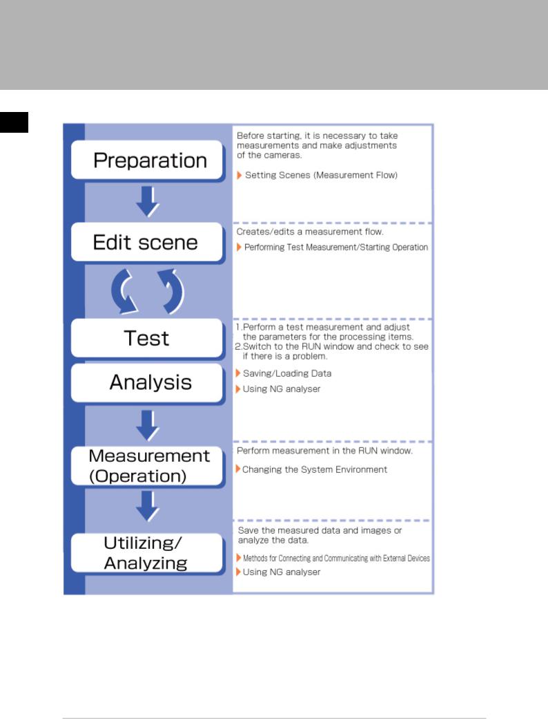
Operation Flow
Here describes the operation flow.
1
Operation Before
10 |
Operation Flow |
FZ3 User's Manual |

Layouts of Screens/Windows |
|
Screens vary with the status of the operation being performed. The structure of some typical screens |
1 |
and the functions for the various buttons are described here. |
|
|
|
|
Operation Before |
Layout of Main Screen (ADJUST Window)
This screen is used to check whether measurement is being performed correctly according to the set conditions.
FZ3 User's Manual |
Layouts of Screens/Windows |
11 |

1
Operation Before
a.Menu Bar
Select operations and settings menus related to measurement.
b.Measurement Information Display Area
1.Overall judgement
Displays a scene's overall judgement result ( [OK]/ [NG]).
2.Processing time
Displays the time required for the measurement process.
3.Status display
Displays the scene group number, scene number, external output status, and image mode for the currently displayed scene.
c.Toolbar
Commonly-used functions appear in the toolbar.
●
●
●
●
Edit flow
The Edit Flow window is displayed. Addition and deletion of processing units and switching of the processing sequence is performed in the Edit Flow window.
Data save
Setting data is saved into the internal flash memory in the controller. Make sure to save when settings have been modified.
Scene switch
To switch a scene group or scene. Measure/Stop meas.
12 |
Layouts of Screens/Windows |
FZ3 User's Manual |
Starts/stops measurement. ● Switch to RUN mode Switches to the RUN window.
d.Image Display Area
Displays the measured image.
1.Property setting buttons
Displays the name of the currently selected processing item.Moving to the property setting window can be done by tapping here.
e.Control Area
Displays "Test measurement", "Flow", "Detail result", and "Image display".
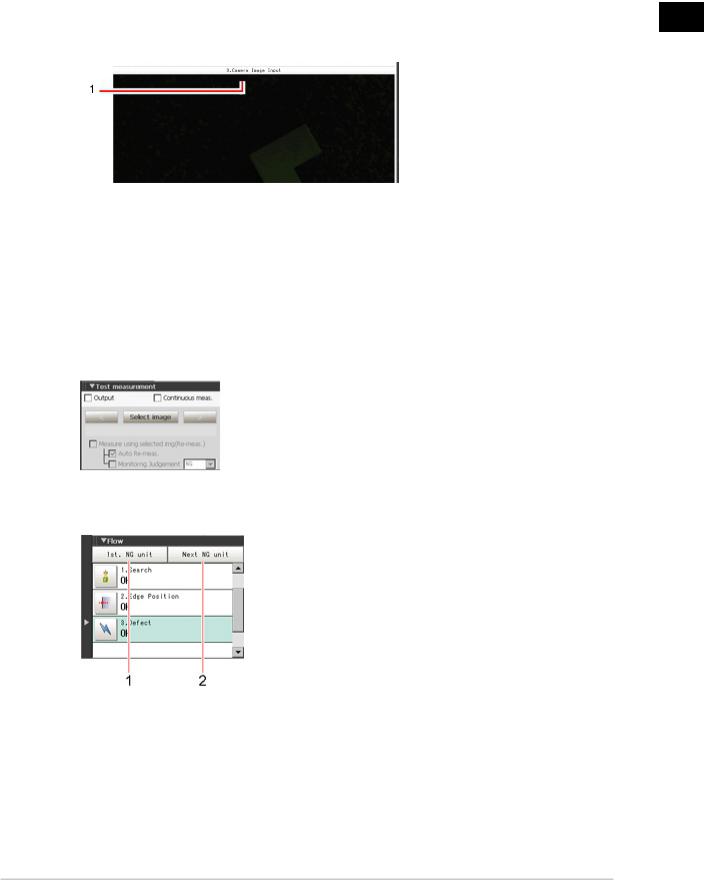
● Test measurement
Use when test measurement conditions and images that have been acquired are used for remeasurement.
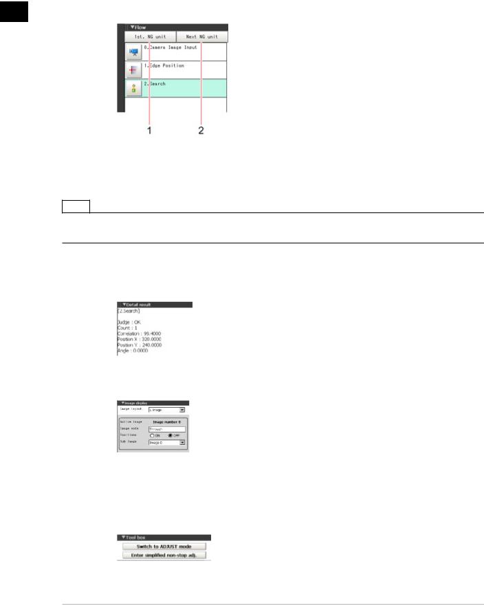
● Flow
Displays the judgement results for the flow and each unit.
1.Moves to the top processing unit with an NG error.
2.Moves to the next processing unit with an NG error.
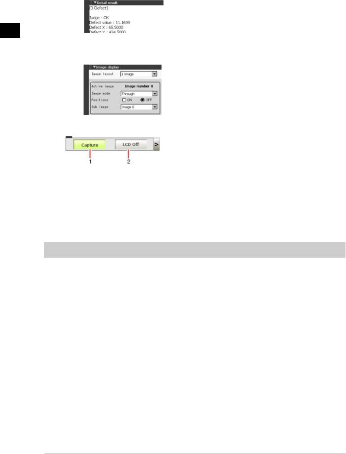
●Detail result
The detailed measurement results of the processing units selected in the measurement flow are displayed as text.
1
Operation Before
FZ3 User's Manual |
Layouts of Screens/Windows |
13 |
1
Operation Before
● Image display
Sets the display method for the Image Display area.
f. Measurement Manager Bar
1.[Capture]
Saves the content displayed on the monitor as an image. Reference:  Set the save destination for captured images. (p.106)
2.[LCD Off] (Displayed only with LCD-integrated controllers.)
Turns off power to the LCD monitor. Tap the bottom of the monitor screen to turn on power to the LCD monitor again.
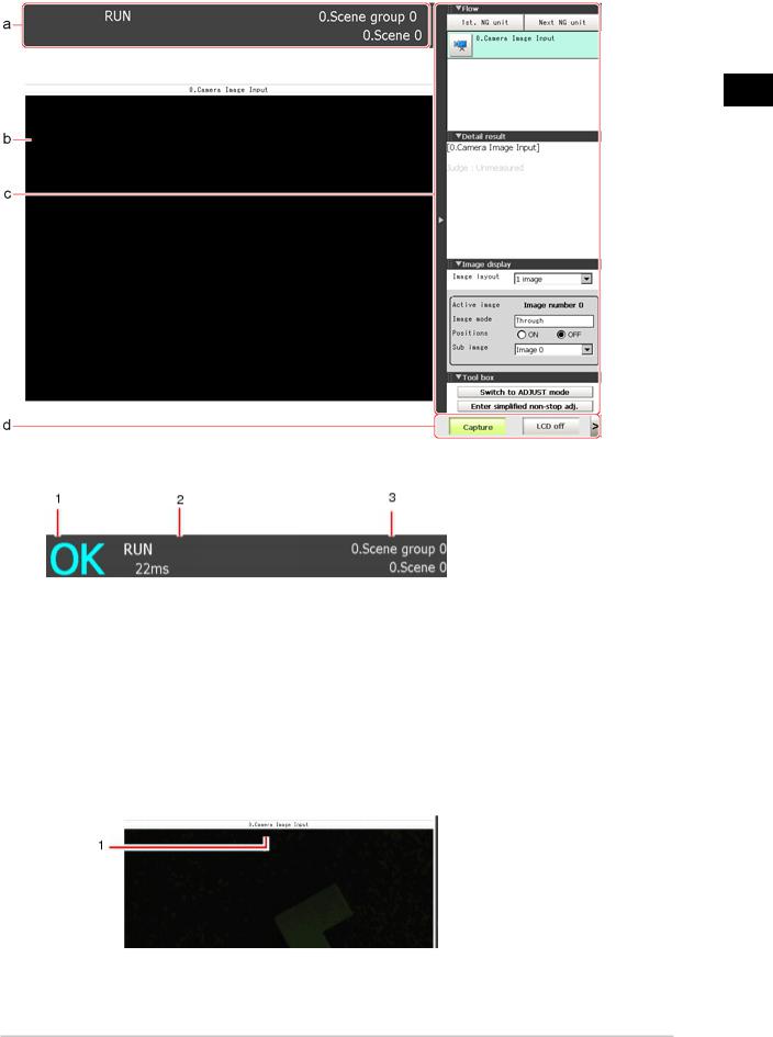
Layout of Main Screen (RUN Window)
This window is used during operation.
14 |
Layouts of Screens/Windows |
FZ3 User's Manual |
1
Operation Before
a. Measurement Information Display Area
1.Overall judgement
Displays a scene's overall judgement result ( [OK]/ [NG]).
The judgement results for each processing unit are displayed in the Control area.
2.Processing time
Displays the time required for the measurement process.
3.Scene Group Name, Scene Name
Displays the scene group number and the scene number of the currently displayed scene.
b.Image Display Area
Displays the measured image.
1.Property setting buttons
Displays the name of the currently selected processing item.
FZ3 User's Manual |
Layouts of Screens/Windows |
15 |
c.Control Area
Displays [Flow], [Detail result], [Image display], and [Tool box].
● Flow
Displays the judgement results for the flow and each unit.
1
Operation Before
1.Moves to the top processing unit with an NG error.
2.Moves to the next processing unit with an NG error.
Note
● The size of the processing unit buttons can be changed through [View] menu - [Display the enlarged flow] in the ADJUST Window.
● Detail result
The detailed measurement results of the processing units selected in the measurement flow are displayed as text.
● Image display
Sets the display method for the Image Display area.
● Tool box
Starts and stops simplified non-stop adjustment, and switches to the ADJUST window.
Items for which operation is performed in the ADJUST window can be allocated to buttons, and they can then be executed in the RUN window.
16 |
Layouts of Screens/Windows |
FZ3 User's Manual |
d. Measurement Manager Bar
1.[Capture]
Saves the content displayed on the monitor as an image. Reference:  Set the save destination for captured images. (p.106)
2.[LCD Off] (Displayed only with LCD-integrated controllers.)
Turns off power to the LCD monitor. Tap the bottom of the monitor screen to turn on power to the LCD monitor again.
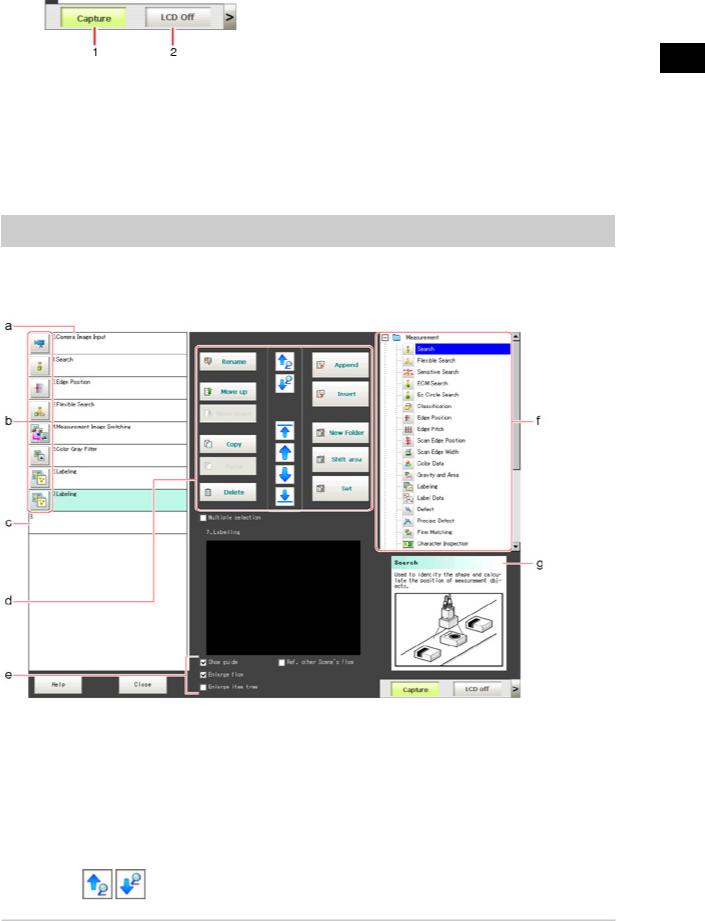
Layout of Edit Flow Window
This window is for compiling the measurement flow.Flow parts are displayed on the right side and the measurement flow is displayed on the left. If the measurement trigger is activated, processing is executed in sequence starting from the top of the flow.
a.Unit List
Lists the processing units included in the flow.
You can create a flow for a scene by adding processing items to the unit list.
b.Property Setting Buttons
Displays the property setting window where detailed settings can be performed.
c.End Marker
Indicates the end of the flow.
d.Edit Flow Buttons
●Search up/Search down
1
Operation Before
FZ3 User's Manual |
Layouts of Screens/Windows |
17 |

1
Operation Before
Searching can be performed to find out what position a processing item occupies in the unit list.
The icon for the processing item to be searched for is selected in the processing item tree and clicked.
This function is convenient when setting long flows.
●Select top/Select bottom
Selects the processing unit at the top or bottom of the flow.
●Select above/Select below
Selects the processing unit located one above or one below the currently selected processing unit.
● Rename
Displays a window for renaming the selected processing unit. ● Move up/Move down
Moves the selected processing unit upward or downward. ● Copy
Copies the selected processing unit. ● Paste
Pastes the copied processing unit immediately before the selected processing unit.Pasting cannot be performed if any operations other than paste are performed after copying.
● Delete
Deletes the selected processing unit. ● Append (Bottom)
Adds a processing unit to the bottom of the flow. ● Insert
Inserts a new processing unit immediately before the selected processing unit. ● New folder
Used when multiple processing units are managed as one group. ● Shift area
Changes related figure data in one batch. ● Multiple selection
Used when processing units are copied or deleted together. ● Set
Displays the processing item setting window for the selected processing unit.
e.Display Options
●Show guide
|
When checked, explanations for processing items are displayed. |
● |
Enlarge flow |
|
When checked, the "a Unit list" flow is displayed with large icons. |
● |
Enlarge item tree |
|
When checked, the "f Processing item tree" is displayed with large icons. |
● |
Ref. other Scene's flow |
|
When checked, other scene flows within the same scene group can be referred to. |
f.Processing Item Tree
This area is for selecting processing items to add to the flow.Processing items are classified by type and displayed as a tree. Tapping the plus sign "+" of any item displays expanded contents
18 |
Layouts of Screens/Windows |
FZ3 User's Manual |
below that item. Tapping the minus sign "-" of any item collapses the expanded contents. When "Ref. other Scene's flow" is checked, the scene select box and other scene flows are displayed.
g.Guide
Shows an explanation for the processing item selected in the processing item tree.These are used as reference when selecting processing items. To display guides, check "Show guide" in "e Display options".
Layout of Property Setting Window
This window is used for detailed setting of measurement parameters and judgement conditions for processing items.
a.Item Tab Area
Displays the settings items for the processing unit currently being set.Perform settings starting with the item on the left.
b.Detail Area
Set detailed items.
c.Image Display Area
Displays camera images, figures, and coordinates.
d.Zoom Browser Area
Zooms in and out from the displayed image.
1
Operation Before
FZ3 User's Manual |
Layouts of Screens/Windows |
19 |
1
Operation Before
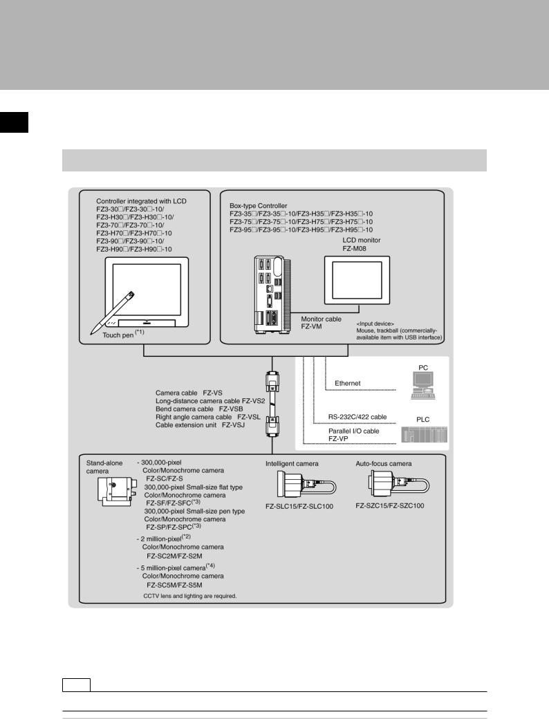
Checking System Configuration
This product is a vision sensor for performing image processing measurement through a controller of objects photographed using a camera. By connecting an external device such as a PC, measurement commands can be input and measurement results can be output from the external device.
Basic Configuration of FZ3 Series
*1: The touch pen is a controller accessory.
*2: FZ-SC2M and FZ-S2M cannot be connected with the FZ3-3  /FZ3-H3
  series. *3: Lenses for small-size cameras are required for small-size 0.3 megapixel cameras. *4: FZ-SC5M/FZ-S5M cannot be connected with the FZ3-3
  /FZ3-H3
  series.
Note
● For details on connector specifications, etc., see the "Operator's Manual (Setup)" of each model.
20 |
Checking System Configuration |
FZ3 User's Manual |

Description of Model-specific Functions
FZ3-9  /H9
/H9  Series Added Functions
Operation mode
Thanks to the dual core CPU, different operation modes can be set to meet different purposes of use. A desired operation mode can be selected from [Parallel-operation high-speed mode], [Single-line high-speed mode], [High-speed logging mode], [Non-stop adjustment mode] and [Multi-line random-trigger mode].
Reference:  Setting Operation Mode (p.30)
Useful processing items when setting up camera
[Focus] (focus adjustment) and [Iris] (iris adjustment) have been added to support camera adjustment during startup.
Reference:  "Processing Item List Manual", "Focus" (p.389)
Reference:  "Processing Item List Manual", "Iris" (p.392)
NG analyser
This tool supports various analysis tasks at startup and during operation, such as identifying optimal thresholds using sample images and finding the causes of problems occurring on the line by analyzing logging images.
Reference:  Using NG Analyser (p.108)
PLC link Support of Mitsubishi Electric Corporation PLC
The MELSEC Q series (by Mitsubishi Electric Corporation) has been added to the list of devices this sensor can communicate with via PLC link.
Reference:  Setting Communication Specifications (Ethernet - PLC Link) (p.151) Reference:
  Setting Communication Specifications (RS-232C/422 - PLC Link) (p.156)
List of model-specific new functions
|
|
|
|
Type of controller |
|
|
||
|
New function |
|
|
|
|
|
|
|
|
FZ3 |
FZ3 |
FZ3 |
FZ3 |
FZ3 |
FZ3 |
||
|
|
-3 |
-H3 |
-7 |
-H7 |
-9 |
-H9 |
|
|
|
|
|
|
|
|
|
|
Function |
|
|
|
|
|
|
|
|
|
|
|
|
|
|
|
||
Operation mode |
- |
- |
- |
- |
○ |
○ |
||
Reference: |
Setting Operation Mode (p.30) |
|||||||
|
|
|
|
|
|
|
|
|
Analyser |
|
- |
- |
- |
- |
○ |
○ |
|
Reference: |
Using NG Analyser (p.108) |
|||||||
|
|
|
|
|
|
|||
|
|
|
|
|
|
|
||
Support of PLC link (MELSEC Q series) |
|
|
|
|
|
|
||
Reference: |
Setting Communication |
|
|
|
|
|
|
|
Specifications (Ethernet - PLC Link) (p.151) |
- |
- |
- |
- |
○ |
○ |
||
Reference: |
Setting Communication |
|
|
|
|
|
|
|
Specifications (RS-232C/422 - PLC Link) (p.156) |
|
|
|
|
|
|
||
|
|
|
|
|
|
|
||
Processing item |
|
|
|
|
|
|
||
|
|
|
|
|
|
|
||
Standard processing item |
○ |
○ |
○ |
○ |
○ |
○ |
||
|
|
|
|
|
|
|
||
Sophisticated processing item (processing |
- |
○ |
- |
○ |
- |
○ |
||
item having + at the end of the item name) |
||||||||
|
|
|
|
|
|
|||
|
|
|
|
|
|
|
|
|
|
|
|
|
|
|
|
|
|
1
Operation Before
FZ3 User's Manual |
Checking System Configuration |
21 |

Usefulprocessingitemswhensettingupcamera |
|
|
|
|
|
|
|
Reference: |
"ProcessingItemListManual","Focus" |
- |
- |
- |
- |
○ |
○ |
(p.389) |
|
||||||
|
|
|
|
|
|
|
|
Reference: |
"ProcessingItemListManual","Iris"(p.392) |
|
|
|
|
|
|
|
|
|
|
|
|
|
|
1
Operation Before
22 |
Checking System Configuration |
FZ3 User's Manual |
Preparing Controllers and Cameras
Preparing Controllers
No special preparation is required with this product as processing items are pre-installed.Please check that the controller is switched on and that the Main screen is displayed.
For details, see the User's Manual.
The first time the program is started up, the Language Setting window is displayed, so select the language.
Reference:  Selecting the Language [Language Setting] (p.131)
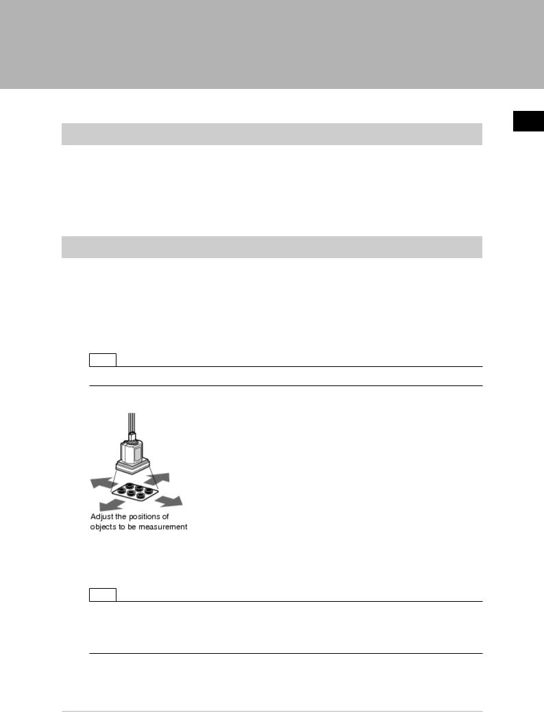
Adjusting Cameras
Confirm what kind of images are being taken.
Adjust the position of measurement objects and the focus of the lens.
1.Tap [  ] of "Image mode" in [Image display] of the Main screen Control area, and select "Through".
The through images captured from the camera are viewed in the Image Display area. Reference:  Changing Display Contents (p.83)
Note
●The same operation is available by tapping [View] - [Image mode] - [Through].
2.Adjust the position of measurement objects so that they display at the center of the monitor.
3.Adjust the focal distance of the lens.
When using an auto-focus camera or an intelligent camera, focus and the iris can be automatically adjusted.
Note
●If a camera is used together with a lens, turn the focus ring of the lens to adjust the focus. Reference:  "Processing Item List Manual", "Lens Setting" (p.21)
●The light intensity of an intelligent camera can be adjusted from the controller. Reference:  "Processing Item List Manual", "Lighting Control" (p.19)
1
Operation Before
FZ3 User's Manual |
Preparing Controllers and Cameras |
23 |

Important
● When using a small-size digital camera, check that the model and serial number of the camera head and camera amplifier match.When a camera head and camera amplifier of different models and serial numbers are connected, they may not operate correctly.
1
Operation Before
Intelligent Camera (with Lighting Function)
Proper lighting is of crucial importance to vision sensors.
If an intelligent camera is connected, lighting can be controlled from the controller.
Features of intelligent cameras are as follows:
●A single camera enables testing of illumination from various angles, so it is possible to shorten the lighting setting time and test measurement time.
●The controller controls lighting, so lighting can be adjusted depending upon the product type.
●Reproducibility of lighting settings is improved.
●Settings can be modified without changing lighting.
Reference:  "Processing Items List Manual", "Screen Adjust Settings (Camera Image Input)" (p.18)
24 |
Preparing Controllers and Cameras |
FZ3 User's Manual |
Input Operations
Input operations differ depending on the type of controller.
●Controller integrated with LCD: Operation with touch pen
●BOX-type controller: Operation with mouse and trackball
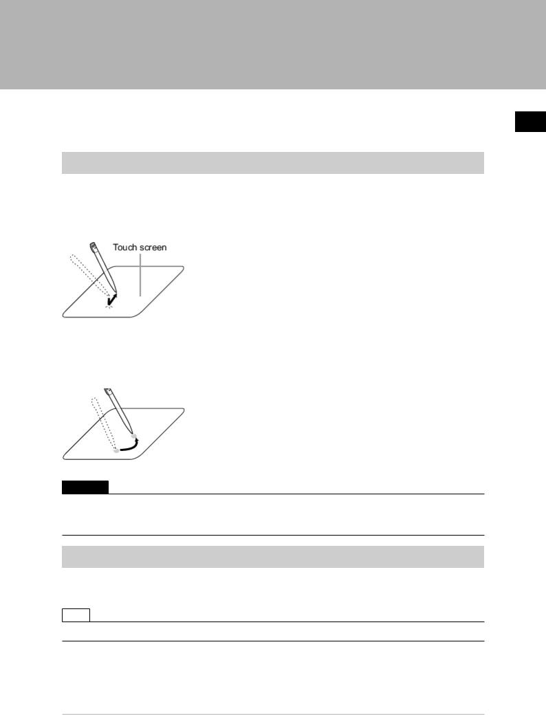
Operation of Touch Pen
With a Controller integrated with LCD, perform the following operations when operating the touch screen with the touch pen.
Tapping
Lightly touch the screen once with the touch pen and immediately take it off. Perform when selecting items, etc.
Drag
Draw while pressing on the screen lightly with the touch pen.
Important
●Be sure to use the supplied touch pen for touch screen operations.Using a pencil or ballpoint pen may damage the touch screen.
●In addition, response to operations may be delayed if the screen is tapped continuously and rapidly.
Basic Operation of Mouse and Trackball
With a BOX-type controller, use a mouse with a USB interface or commercially-available trackball. (See the list for recommended products. Please refer to the product catalog.)
Note
● Do not use the right mouse button, scroll wheel, or other buttons.
1
Operation Before
FZ3 User's Manual |
Input Operations |
25 |

1
Operation Before
Click
Press the left mouse button once. Perform when selecting items, etc.
Note
● This document primarily describes operations using the term "tapping". When using a mouse or trackball, read "Tapping" to mean "Clicking".
Drag
Move the mouse with the left mouse button held down.
26 |
Input Operations |
FZ3 User's Manual |
Returning Controller to Factory Settings
All controller settings can be restored to factory default status (initialization). In addition, the controller can be restarted.
●Reference:  Initializing Controller [System Initialization] (p.27)
●Reference:  Restarting Controller [System Restart] (p.27)
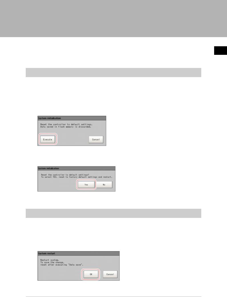
Initializing Controller [System Initialization]
Restores the controller to factory default status. Before initialization, back up required data such as scene data and system data.
Reference:  Saving Settings Data to RAMDisk/USB Device (p.120)
1.On the Main screen, tap [System] - [Controller] - [System initialization]. The System Initialization window is displayed.
2.Tap [Execute].
A confirmation window is displayed. 3. Tap [Yes].
The controller is initialized and restarts.
Restarting Controller [System Restart]
Restart the controller. Before restarting, back up required data such as scene data and system data. Reference:  Saving Settings Data to Controller Memory (p.118)
1.On the Main screen, tap [System] - [Controller] - [System restart]. The System Restart window is displayed.
2.Tap [OK].
The controller restarts.
1
Operation Before
FZ3 User's Manual |
Returning Controller to Factory Settings |
27 |
1
Operation Before
Saving Settings and Turning Power Off
Before turning off power to the controller, perform the following operations to save the data that you have set.
The controller loads scene data from the flash memory each time during start-up. Therefore, if the power is turned off without saving data to the flash memory, any changes made will not be saved.
1.On the Main screen (ADJUST window), tap [Data save] in the toolbar to save the setting data.
2.Exit after powering off the controller.
Note
● Data to be saved
Scene data and system data are saved in the controller. Logging images and data saved in the RAMDisk are not saved. Perform any of the following procedures to keep this data.
-Copy data saved in the RAMDisk to the USB memory. Reference:  Copying/Moving Files (p.124)
-Change the save destination of logging data to USB memory. Reference:  Saving Logging Images to RAMDisk/USB Device (p.122)
●When using the scene group function
The scene data set in Scene group 0 is saved in the controller. The scene data from scene groups 1 to 31 is saved to the USB memory and overwrites previous saved data. (For FZ3-9  /H9
/H9  , all data are saved in the controller.)
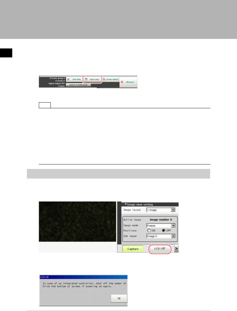
Turning Off LCD
This function is specific to FZ3-300/700/900 series LCD-integrated controllers.
Turn off the LCD only without turning off the controller.
1. Open the measurement manager bar at the bottom right of the Main screen and tap [LCD Off].
A confirmation message is displayed. 2. Tap [OK].
28 |
Saving Settings and Turning Power Off |
FZ3 User's Manual |
Loading...