


E5AK
Digital Controller
User's Manual
Cat. No. H083-E1-03


 Preface
Thank you for your purchase of your E5AK, intelligent digital controller. The E5AK allows the user to carry out the following:
•Select from many types of temperature and analog input (multiple input)
•Support position-proportional control (position-proportional type controllers only).
•Select output functions such as control output or alarm (output assignment)
•Use the HBA (heater burnout alarm) function (standard type controllers only).
•Use four setpoints (multi-SP function)
•Use remote SP input.
•Monitor the control loop by LBA (Loop Break Alarm)
•Use the communications function
•Calibrate input or transfer output
•It also features a watertight construction (NEMA4: equivalent to IP66)
This User’s Manual describes how to use the E5AK compact, high-function digital controller.
Before using your E5AK, thoroughly read and understand this manual in order to ensure correct use.
About this manual
E OMRON, 1996
(1)All rights reserved. No part of this publication may be reproduced, stored in a retrieval system, or transmitted, in any form, or by any means, mechanical, electronic, photocopying, recording, recording, or otherwise, without the prior written permission of OMRON.
(2)No patent liability is assumed with respect to the use of the information contained herein.
(3)Moreover, because OMRON is constantly striving to improve its high-quality products, the information in this manual is subject to change without notice. Every precaution has been taken in the preparation of this manual. Nevertheless, OMRON assumes no responsibility for errors or omissions. Neither is any liability assumed for damages resulting from the use of the information contained in this publication.
I

 Conventions Used in This Manual
JMeanings of Abbreviations
Sometimes the following abbreviations are used in parameter names, figures and in text explanations. These abbreviations mean the following.
Abbreviation |
Term |
|
|
PV |
Process value |
SP |
Set point |
RSP |
Remote set point |
LSP |
Local set point |
LBA |
Loop break alarm |
HB |
Heater burnout |
AT |
Auto-tuning |
ST |
Self-tuning |
|
|
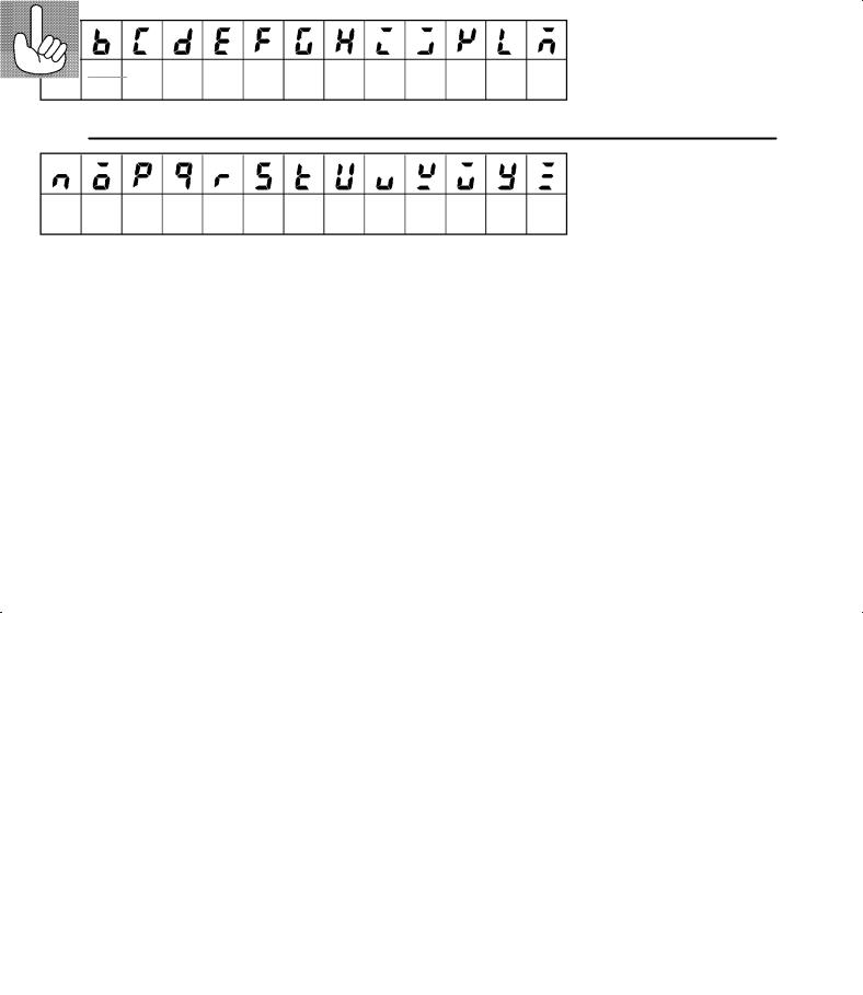
JHow to Read Display Symbols
The following tables show the correspondence between the symbols displayed on the displays and alphabet characters.
A B C D E F G H I J K L M
N O P Q R S T U V W X Y Z
J“Reference” mark
This mark indicates that extra, useful information follows, such as supplementary explanations and how to apply functions.
II

JNotice:
OMRON products are manufactured for use according to proper procedures by a qualified operator and only for the purposes described in this manual.
The following conventions are used to indicate and classify precautions in this manual. Always heed the information provided with them. Failure to heed precautions can result in injury to people or damage to the product.
!DANGER
!WARNING
!Caution
Indicates information that, if not heeded, is likely to result in loss of life or serious injury.
Indicates information that, if not heeded, could possibly result in loss of life or serious injury.
Indicates information that, if not heeded, could result in relatively serious or minor injury, damage to the product, or faulty operation.
III

JHow this Manual is Organized
Purpose |
Title |
Description |
D Learning about the gen- |
Chapter 1 Introduction |
This chapter describes the fea- |
eral features of the E5AK |
|
tures of the E5AK, names of |
|
parts, and typical functions. |
|
|
|
|
D Setting up the E5AK |
Chapter 2 Preparations |
This chapter describes the |
|
|
operations that you must carry |
|
|
out (e.g. installation, wiring and |
|
|
switch settings) before you can |
|
|
use the E5AK. |
D Basic E5AK operations |
Chapter 3 Basic Operation |
These chapters describe how to |
|
Chapter 5 Parameters |
use the front panel keys and |
|
|
how to view the display when |
|
|
setting the parameters of the |
|
|
major functions for the E5AK. |
D Applied E5AK operations |
Chapter 4 Applied Opera- |
These chapters describe the |
|
tion |
important functions of the |
|
Chapter 5 Parameters |
E5AK and how to use the |
|
|
parameters for making full use |
|
|
of the E5AK. |
D Using a Position-propor- |
Chapter 4 Applied Opera- |
This chapter describes the func- |
tional Type Controller |
tion/4.1 Selecting the Con- |
tions related specifically to posi- |
trol Method |
tion-proportional type control- |
|
|
|
lers. |
D Communications with a |
Chapter 6 Using the Com- |
This chapter mainly describes |
host computer |
munications Function |
the communications commands, |
|
and gives program examples. |
|
|
|
|
D Calibration |
Chapter 7 Calibration |
This chapter describes how the |
|
|
user should calibrate the E5AK. |
D Troubleshooting |
Chapter 8 Troubleshooting |
This chapter describes what to |
|
|
do if any problems occur. |
|
|
|
IV

Pay Attention to the Following when Installing this Controller
F If you remove the controller from its case, never touch nor apply shock to the electronic parts inside.
F Do not cover the area around the E5AK. (Ensure sufficient space around the controller to allow heat radiation.)
F Use a voltage (AC100-240V or AC/DC24V
 at 50 to 60 Hz). At power ON, the prescribed voltage level must be attained within two seconds.
F When wiring input or output lines to your controller, keep the following points in mind to reduce the influence from inductive noise:
•Allow adequate space between the high voltage/current power lines and the input/ output lines.
•Avoid parallel or common wiring with high voltage sources and power lines carrying large currents.
•Using separating pipes, duct, and shielded line is also useful in protecting the controller, and its lines form inductive noise.
F Allow as much space as possible between the controller and devices that generate a powerful, high frequency (high-frequency welders, high-frequency sewing machines, and so forth) or surge. These devices may cause malfunctions.
F If there is a large power-generating peripheral device and any of its lines, attach a surge suppressor or noise filter to the device to stop the noise affecting the controller system. In particular, motors, transformers, solenoids and magnetic coils have an inductance component, and therefore can generate very strong noises.
F When mounting a noise filter, be sure to first check the filter’s voltage and current capacity, then mount the filter as close as possible to the controller.
F Do not use the controller in places where icing, condensation, dust, corrosive gas (especially sulfurized gas or ammonia gas), shock, vibration, splashing liquid, or oil atmosphere occur. Also, avoid places where the controller can be subjected to intense heat radiation (like from a furnace) or sudden temperature changes.
F Ambient temperature must be kept between -10_C to 55_C. Ambient humidity must be kept between 35%RH to 85%RH (with no icing or condensation). If the controller is installed inside a control board, the ambient temperature must be kept under 55_C, including the temperature around the controller. If the controller is subjected to heat radiation, use a fan to cool the surface of the controller to under 55_C.
F Store the controller at an ambient temperature between -25_C to 65_C. The ambient humidity must be between 35%RH to 85%RH (with no icing or condensation).
F Never place heavy objects on, or apply pressure to the controller that may cause it to deform and deterioration during use or storage.
F Avoid using the controller in places near a radio, television set, or wireless installation. These devices can cause radio disturbances which adversely affect the performance of the controller.
V


 Table of Contents
|
. . . . . . . . . . . . . . . . . . . . . . . . . . . . . . . . . . . . . .Preface |
I |
|
Conventions Used in This Manual . . . . . . . . . . . . . . . |
II |
|
Pay Attention to the Following when Installing |
|
|
this Controller . . . . . . . . . . . . . . . . . . . . . . . . . . . . . . . . . |
V |
|
|
|
CHAPTER 1 INTRODUCTION . . . . . . . . . . . . . . . . . . . . . . . . . . . |
1--1 |
|
|
This chapter introduces the E5AK. First-time users should read this chapter with- |
|
|
out fail. |
|
|
For details on how to use the controller and parameter settings, see Chapters 2 |
|
|
onwards. |
|
1.1 |
Names of parts . . . . . . . . . . . . . . . . . . . . . . . . . . . . . . . . . . . . . . . . . . |
1--2 |
1.2 |
Input and Output . . . . . . . . . . . . . . . . . . . . . . . . . . . . . . . . . . . . . . . . . |
1--4 |
1.3 |
Parameters and Menus . . . . . . . . . . . . . . . . . . . . . . . . . . . . . . . . . . . |
1--7 |
1.4 |
About the Communications Function . . . . . . . . . . . . . . . . . . . . . . . |
1--10 |
1.5 |
About Calibration . . . . . . . . . . . . . . . . . . . . . . . . . . . . . . . . . . . . . . . . |
1--11 |
CHAPTER 2 PREPARATIONS . . . . . . . . . . . . . . . . . . . . . . . . . . . |
2--1 |
|
|
This chapter describes the operations you should carry out before turning the |
|
|
E5AK ON. |
|
2.1 |
Setting up . . . . . . . . . . . . . . . . . . . . . . . . . . . . . . . . . . . . . . . . . . . . . . . |
2--2 |
2.2 |
Installation . . . . . . . . . . . . . . . . . . . . . . . . . . . . . . . . . . . . . . . . . . . . . . |
2--5 |
2.3 |
Wiring Terminals . . . . . . . . . . . . . . . . . . . . . . . . . . . . . . . . . . . . . . . . . |
2--8 |
CHAPTER 3 BASIC OPERATION . . . . . . . . . . . . . . . . . . . . . . . . |
3--1 |
|
|
This chapter describes an actual example for understanding the basic operation |
|
|
of the E5AK. |
|
3.1 |
Convention Used in this Chapter . . . . . . . . . . . . . . . . . . . . . . . . . . . |
3--2 |
3.2 |
Setting Input Specifications . . . . . . . . . . . . . . . . . . . . . . . . . . . . . . . |
3--4 |
3.3 |
Setting Output Specifications . . . . . . . . . . . . . . . . . . . . . . . . . . . . . . |
3--6 |
3.4 |
Setting Alarm Type . . . . . . . . . . . . . . . . . . . . . . . . . . . . . . . . . . . . . . . |
3--9 |
3.5 |
Protect Mode . . . . . . . . . . . . . . . . . . . . . . . . . . . . . . . . . . . . . . . . . . . . |
3--12 |
3.6 |
Starting and Stopping Operation . . . . . . . . . . . . . . . . . . . . . . . . . . . |
3--13 |
3.7 |
Adjusting Control Operation . . . . . . . . . . . . . . . . . . . . . . . . . . . . . . . |
3--14 |
CHAPTER 4 APPLIED OPERATION . . . . . . . . . . . . . . . . . . . . . . |
4--1 |
|
|
This chapter describes each of the parameters required for making full use of the |
|
|
features of the E5AK. Read this chapter while referring to the parameter descrip- |
|
|
tions in chapter 5. |
|
4.1 |
Selecting the Control Method . . . . . . . . . . . . . . . . . . . . . . . . . . . . . . |
4--2 |
4.2 |
Operating Condition Restrictions . . . . . . . . . . . . . . . . . . . . . . . . . . . |
4--5 |
4.3 |
How to Use Event Input . . . . . . . . . . . . . . . . . . . . . . . . . . . . . . . . . . |
4--8 |
4.4 |
How to Use the Remote SP . . . . . . . . . . . . . . . . . . . . . . . . . . . . . . . |
4--11 |
4.5 |
How to Use the Heater Burnout Alarm . . . . . . . . . . . . . . . . . . . . . . |
4--13 |
4.6 |
LBA . . . . . . . . . . . . . . . . . . . . . . . . . . . . . . . . . . . . . . . . . . . . . . . . . . . . |
4--15 |
4.7 |
How to Use Transfer Output . . . . . . . . . . . . . . . . . . . . . . . . . . . . . . . |
4--17 |
CHAPTER 5 PARAMETERS . . . . . . . . . . . . . . . . . . . . . . . . . . . . . |
5--1 |
This chapter describes the parameters of the E5AK. Use this chapter as a refer- |
|
ence guide. |
|
Protect Mode . . . . . . . . . . . . . . . . . . . . . . . . . . . . . . . . . . . . . . . . . . . . . . . . |
5--3 |
Manual Mode . . . . . . . . . . . . . . . . . . . . . . . . . . . . . . . . . . . . . . . . . . . . . . . . |
5--5 |
Level 0 Mode . . . . . . . . . . . . . . . . . . . . . . . . . . . . . . . . . . . . . . . . . . . . . . . . |
5--6 |
Level 1 Mode . . . . . . . . . . . . . . . . . . . . . . . . . . . . . . . . . . . . . . . . . . . . . . . . |
5--10 |
Level 2 Mode . . . . . . . . . . . . . . . . . . . . . . . . . . . . . . . . . . . . . . . . . . . . . . . . |
5--18 |
Setup Mode . . . . . . . . . . . . . . . . . . . . . . . . . . . . . . . . . . . . . . . . . . . . . . . . . |
5--25 |
Expansion Mode . . . . . . . . . . . . . . . . . . . . . . . . . . . . . . . . . . . . . . . . . . . . . |
5--32 |
Option Mode . . . . . . . . . . . . . . . . . . . . . . . . . . . . . . . . . . . . . . . . . . . . . . . . . |
5--37 |
Calibration Mode . . . . . . . . . . . . . . . . . . . . . . . . . . . . . . . . . . . . . . . . . . . . . |
5--46 |
CHAPTER 6 USING THE COMMUNICATIONS FUNCTION . . |
6--1 |
|
|
This chapter mainly describes communications with a host computer and com- |
|
|
munications commands. |
|
6.1 |
Outline of the Communications Function . . . . . . . . . . . . . . . . . . . . |
6--2 |
6.2 |
Preparing for Communications . . . . . . . . . . . . . . . . . . . . . . . . . . . . |
6--3 |
6.3 |
Command Configuration . . . . . . . . . . . . . . . . . . . . . . . . . . . . . . . . . . |
6--5 |
6.4 |
Commands and Responses . . . . . . . . . . . . . . . . . . . . . . . . . . . . . . . |
6--6 |
6.5 |
How to Read Communications Error Information . . . . . . . . . . . . . |
6--12 |
6.6 |
Program Example . . . . . . . . . . . . . . . . . . . . . . . . . . . . . . . . . . . . . . . |
6--14 |
CHAPTER 7 CALIBRATION . . . . . . . . . . . . . . . . . . . . . . . . . . . . . |
7--1 |
|
|
This chapter describes procedures for each calibration operation. |
|
|
Read this chapter only when the controller must be calibrated. |
|
7.1 |
Structure of Parameters . . . . . . . . . . . . . . . . . . . . . . . . . . . . . . . . . . |
7--2 |
7.2 |
Calibrating Thermocouple . . . . . . . . . . . . . . . . . . . . . . . . . . . . . . . . . |
7--4 |
7.3 |
Calibrating Platinum Resistance Thermometer . . . . . . . . . . . . . . |
7--7 |
7.4 |
Calibrating Current Input . . . . . . . . . . . . . . . . . . . . . . . . . . . . . . . . . . |
7--9 |
7.5 |
Calibrating Voltage Input . . . . . . . . . . . . . . . . . . . . . . . . . . . . . . . . . . |
7--10 |
7.6 |
Checking Indication Accuracy . . . . . . . . . . . . . . . . . . . . . . . . . . . . . |
7--12 |
CHAPTER 8 TROUBLESHOOTING . . . . . . . . . . . . . . . . . . . . . . |
8--1 |
|
|
This chapter describes how to find out and remedy the cause if the E5AK does |
|
|
not function properly. |
|
8.1 |
Initial Checks . . . . . . . . . . . . . . . . . . . . . . . . . . . . . . . . . . . . . . . . . . . . |
8--2 |
8.2 |
How to Use the Error Display . . . . . . . . . . . . . . . . . . . . . . . . . . . . . . |
8--3 |
8.3 |
How to Use Error Output . . . . . . . . . . . . . . . . . . . . . . . . . . . . . . . . . . |
8--5 |
8.4 |
Checking Operation Restrictions . . . . . . . . . . . . . . . . . . . . . . . . . . . |
8--6 |
APPENDIX
SPECIFICATIONS . . . . . . . . . . . . . . . . . . . . . . . . |
A--2 |
ABOUT CURRENT TRANSFORMER (CT) . . . |
A--5 |
CONTROL BLOCK DIAGRAM . . . . . . . . . . . . . . |
A--6 |
SETTING LIST . . . . . . . . . . . . . . . . . . . . . . . . . . . |
A--8 |
MODEL LIST . . . . . . . . . . . . . . . . . . . . . . . . . . . . . |
A--11 |
PARAMETER OPERATIONS LIST . . . . . . . . . . |
A--12 |
FUZZY SELF-TUNING . . . . . . . . . . . . . . . . . . . . |
A--14 |
X FORMAT . . . . . . . . . . . . . . . . . . . . . . . . . . . . . . . |
A--17 |
ASCII CODE LIST . . . . . . . . . . . . . . . . . . . . . . . . |
A--20 |
INDEX
REVISION HISTORY

CHAPTER 1 INTRODUCTION 

CHAPTER1
INTRODUCTION
This chapter introduces the E5AK. First-time users should read this chapter without fail.
For details on how to use the controller and parameter settings, see Chapters 2 onwards.
1.1 |
Names of parts . . . . . . . . . . . . . . . . . . . . . . . . |
1-2 |
|
Main parts . . . . . . . . . . . . . . . . . . . . . . . . . . . . |
1-2 |
|
Front panel . . . . . . . . . . . . . . . . . . . . . . . . . . . |
1-2 |
|
About the displays . . . . . . . . . . . . . . . . . . . . . |
1-3 |
|
How to use keys . . . . . . . . . . . . . . . . . . . . . . . |
1-3 |
1.2 |
Input and Output . . . . . . . . . . . . . . . . . . . . . . |
1-4 |
|
Input . . . . . . . . . . . . . . . . . . . . . . . . . . . . . . . . . |
1-4 |
|
Output . . . . . . . . . . . . . . . . . . . . . . . . . . . . . . . . |
1-5 |
1.3 |
Parameters and Menus . . . . . . . . . . . . . . . . . |
1-7 |
|
Parameter types . . . . . . . . . . . . . . . . . . . . . . . |
1-7 |
|
Selecting modes . . . . . . . . . . . . . . . . . . . . . . . . |
1-8 |
|
Selecting parameters . . . . . . . . . . . . . . . . . . . |
1-9 |
|
Fixing settings . . . . . . . . . . . . . . . . . . . . . . . . . |
1-9 |
1.4 |
About the Communications Function . . . . |
1-10 |
1.5 |
About Calibration . . . . . . . . . . . . . . . . . . . . . . |
1-11 |
1--1


 CHAPTER 1 INTRODUCTION
1.1 Names of parts
JMain parts
Terminals
P 2-8
Rear case
Front panel This page
JFront panel
Bar graph |
PV |
No.1 display |
|
|
SV |
Operation indicators
OUT1 OUT2 SUB1 SUB2 MANU
STOP
RMT
RST
AT
No.2 display
RMT |
RSP |
MANU |
SUB1 |
SUB2 |
OUT1 |
OUT2 |
STOP |
AT |
|
E5AK
A/M key |
Display key |
Down key |
Up key |
A/M
1--2
|
|
1.1 Names of parts |
|
|
|
|
|
JAbout the displays |
|
|
|
F No.1 display |
Displays the process value or parameter symbols. |
||
F No.2 display |
Displays the set point, manipulated variable or parameter settings. |
||
F Operation indica- |
• OUT1 |
: Lit when the pulse output function assigned to “control |
|
tors |
|
output 1” is ON. |
|
|
• OUT2 |
: Lit when the pulse output function assigned to “control |
|
|
|
output 2” is ON. |
|
|
• SUB1 |
: Lit when the output function assigned to “auxiliary output |
|
|
|
1” is ON. |
|
|
• SUB2 |
: Lit when the output function assigned to “auxiliary |
|
|
|
output 2” is ON. |
|
|
• MANU |
: Lit in the manual operation mode. |
|
|
• STOP |
: Lit when operation has stopped. |
|
|
• RMT |
: Lit during remote operation. |
|
|
• RSP |
: Lit during remote SP operation. |
|
|
• AT |
: Flashes during auto-tuning. |
|
F Bar graph |
On a standard type controller (E5AK-AA2), this bar graph indicates the |
||
|
manipulated variable (heat) in 10% increments per single segment. On |
||
a position-proportional type controller (E5AK-PRR2), this bar graph indicates the valve opening in 10% increments per single segment.
JHow to use keys
F  key
key
F  key
key
The following describes basic key operations.
Each press of this key switches between the auto and manual operations.
The functions of this key change according to how long it is pressed. If the key is pressed for less than one second, the parameters are switched. If the key is pressed for one second or more, the menu display appears. In key operations from here on, “press the key” refers to pressing the key for less than one second.
For details on parameter switching and menu display items, see page 1-8.
F |
key |
Each press of the |
key increments or advances the values or settings |
|
|
|
on the No.2 display, while each press of the |
key decrements or |
|
|
|
returns the values or settings on the No.2 display. |
||
Functions vary, for example, when the  key is held down simultaneously with the display key, or a key is held down continuously. For details, see page 1-8. Also, chapters 3 and 4 describe examples using various key combinations.
1--3

 CHAPTER 1 INTRODUCTION
1.2 Input and Output
|
|
|
|
Temperature input |
Controller |
Control output |
Control output 1 |
|
(heat) |
||
Voltage input |
|
Control output |
|
Current input |
|
|
|
|
|
(cool) |
|
|
|
Alarm 1 |
Control output 2 |
|
|
|
|
CT input |
|
|
|
Potentiometer |
|
Alarm 2 |
Auxiliary output 1 |
|
|
||
|
|
|
|
|
|
Alarm 3 |
|
Remote SP input |
|
HBA |
Auxiliary output 2 |
|
|
LBA |
|
Event input |
|
Error 1 |
Transfer output |
|
|
Error 2 |
|
|
|
Error 3 |
|
JInput
The E5AK supports following inputs: temperature input, current input, voltage input, CT input/Potentiometer, remote SP input and event input.
F Temperature input/Voltage input/Current input
FCT input/Potentiometer
•Only one of temperature input, voltage input and current input can be selected and connected to the controller. The above figure shows temperature input connected to the controller.
•The following input sensors can be connected for temperature input: Thermocouple: K, J, T, E, L, U, N, R, S, B, W, PLII
Platinum resistance thermometer: JPt100, Pt100
•The following currents can be connected for current input:
4 to 20 mA, 0 to 20 mA
•The following voltages can be connected for voltage input:
1to 5 VDC, 0 to 5 VDC, 0 to 10 VDC
•Connect CT input when using the HBA (heater burnout alarm) function on a standard type controller (E5AK-AA2).
•Connect the potentiometer when monitoring the valve opening on a position-proportional type controller (E5AK-PRR2).
F Remote SP input When the remote SP function is enabled, inputs within the range 4 to 20 mA are used as the remote SP.
1--4

|
1.1 Names of parts |
|
|
|
|
F Event input |
When using event input, add on the input unit (E53-CKB). |
|
|
You can select from the following five event inputs: |
|
|
Multi-SP |
|
|
Run/Stop |
|
|
Remote/Local |
|
|
Auto/Manual |
|
|
SP mode |
|
JOutput
FOutput assignments
The E5AK supports the following five outputs. Control output 1
Control output 2 Auxiliary output 1 Auxiliary output2 Transfer output
When using control outputs 1 and 2, set the output unit (sold separately). Nine output units are available to suit the output circuit configuration.
When using transfer output, add on the communication unit (E53-AKF).
Note: The output functions of the E5AK do not operate for five seconds after the E5AK is turned ON.
The E5AK supports the following ten output functions.
Control output (heat) Control output (cool) Alarms 1 to 3
HBA
LBA
Error 1 (input error)
Error 2 (A/D converter error) Error 3 (RSP input error)
Assign these output functions to control output 1, control output 2, auxiliary output1, and auxiliary output2.
However, note that as control output 1 is used as the open output and control output 2 is used as close output on a position-proportional type controller (E5AK-PRR2), control outputs 1 and 2 cannot be used as assignment destinations. Also, of the output functions, control output (heat), control output (cool), HBA and LBA are disabled.
On a standard type controller, there are restrictions on how assignment destinations (control output 1, control output2, auxiliary output1, and auxiliary output2) can be used. For details, see 3.3 Setting Output Specifications.
In the example on the previous page, “control output (heat)” is assigned to “control output 1”, “alarm 1” is assigned to “control output 2”, and “alarm 2” is assigned to “auxiliary output 1”. Accordingly, the configuration is such that heating control output is connected to control output 1, and alarm output is connected to control output 2 and auxiliary output 1.
1--5


 CHAPTER 1 INTRODUCTION
Control outputs 1 and 2 are used depending on the differences in control method as follows.
Control Method |
Model |
Control Output 1/ |
|
Control Output 2 |
|||
|
|
||
|
|
|
|
Standard control |
E5AK-AA2 AC100-240 |
Control output (heat) / |
|
|
E5AK-AA2 AC/DC24 |
Alarm, etc., |
|
|
|
|
|
Heating and cooling |
E5AK-AA2 AC100-240 |
Control output (heat) / |
|
control |
E5AK-AA2 AC/DC24 |
Control output (cool) |
|
|
|
|
|
Position-proportional |
E5AK-PRR2 AC100-240 |
Open/Close |
|
control |
E5AK-PRR2 AC/DC24 |
|
F Transfer output |
The E5AK supports the following six transfer outputs. |
|
Set point |
|
Set point during SP ramp |
|
Process value |
|
Heating side manipulated variable |
|
Cooling side manipulated variable |
|
Valve opening |
|
However, note that heating/cooling side manipulated variables can be |
|
output only standard type controllers, and valve opening can be output |
|
on position-proportional type controllers |
|
These transfer outputs can be output after being scaled. Setting of an |
|
upper limit value smaller than the lower limit value is allowed, so |
|
reverse scaling can also be carried out. |
1--6

1.1 Names of parts 

1.3 Parameters and Menus
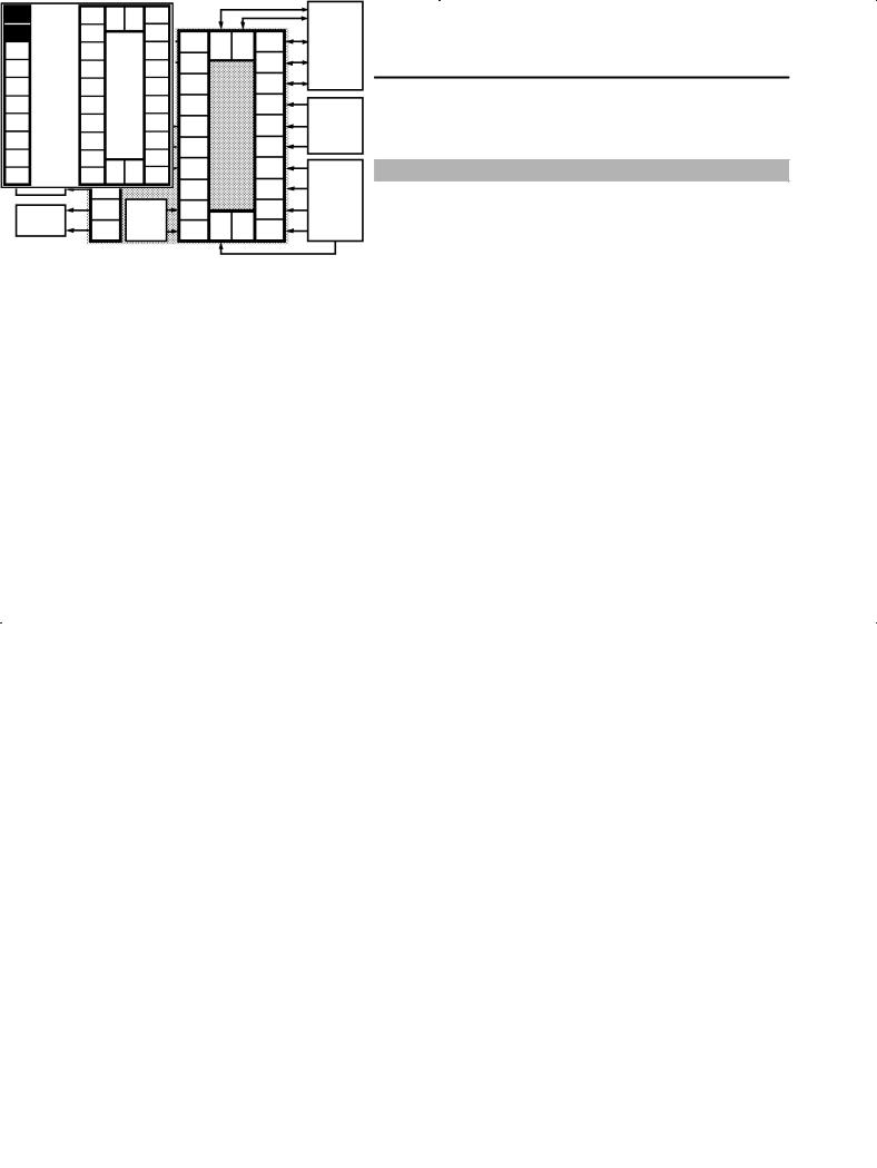
JParameter types
F Protect mode
E5AK parameters are distributed between the following nine modes. Protect mode
Manual mode Level 0 mode Level 1 mode Level 2 mode Setup mode Expansion mode Option mode Calibration mode
The settings of parameters in each of seven modes (excluding the protect mode and manual mode) can be checked and modified by selection on the menu display.
This mode is used to limit use of the menu and  keys. The protect function is for preventing unwanted modification of parameters and switching between the auto and manual operation.
F Manual mode |
In this mode, the controller can be switched manual operation. The |
|
manipulated variable can be manipulated manually only in this mode. |
F Level 0 mode |
Set the controller to this mode during normal operation. In this mode, |
|
you may change the set point during operation, and stop and start op- |
|
eration. You can also monitor (not change) the process value, ramp SP |
|
and manipulated variable. |
F Level 1 mode |
This is the main mode for adjusting control. In this mode, you can |
|
execute AT (auto-tuning), and set alarm values, the control period and |
|
PID parameters. |
F Level 2 mode |
This is the auxiliary mode for adjusting control. In this mode, you can |
|
set the parameters for limiting the manipulated variable, switch |
|
between the remote and local modes, switch between the SP modes, and |
|
set the loop break alarm (LBA), alarm hysteresis and the digital filter |
|
value of inputs. |
F Setup mode |
This is the mode for setting the basic specifications. In this mode, you |
|
can set parameters that must be checked or set before operation such as |
|
the input type, scaling, output assignments and direct/reverse opera- |
|
tion. |
F Expansion mode |
This is the mode for setting expanded functions. In this mode, you can |
|
set ST (self-tuning), SP setting limiter, selection of advanced PID or |
|
ON/OFF control, specification of the standby sequence resetting |
|
method, time for automatic return to the monitoring display. |
F Option mode |
This is the mode for setting option functions. You can select this mode |
|
only when the option unit is set in the controller. In this mode, you can |
|
1--7 |


 CHAPTER 1 INTRODUCTION
|
set the communications conditions, transfer output and event input |
||
|
parameters to match the type of option unit set in the controller. Heater |
||
|
burnout latch function, position-proportional travel time and remote |
||
|
SP scaling parameters are also located in this mode. |
|
|
F Calibration mode |
This mode is provided so that the user can calibrate inputs and transfer |
||
|
output. |
|
|
|
When calibrating input, the selected input type is calibrated. Whereas, |
||
|
transfer output can be calibrated only when the communications unit |
||
|
(E53-AKF) is set in the controller. |
|
|
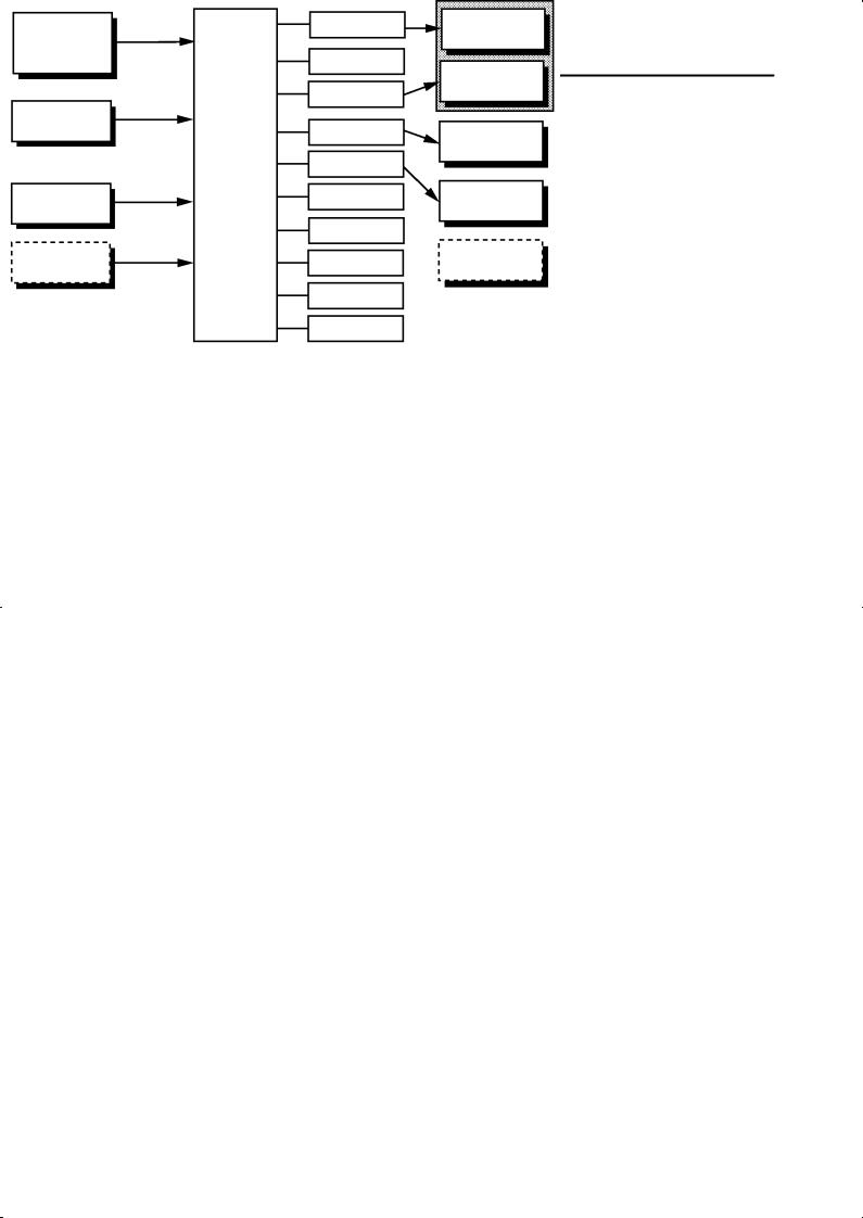
JSelecting modes |
The following diagram shows the order in which modes are selected. |
||
|
Power ON |
|
|
|
|
A/M |
|
|
1 second min. |
1 second min. |
|
|
Level 0 mode |
|
Manual mode |
|
1 second min. |
|
A/M |
|
Level 1 mode |
|
1 second min. |
|
|
|
|
|
1 second min. |
|
|
|
Level 2 mode |
A/M + |
A/M + |
|
|
1 second min. |
1 second min. |
|
1 second min. |
|
|
|
Setup mode |
|
Protect mode |
|
|
|
|
|
1 second min. |
|
|
|
Expansion mode |
|
A/M + |
1 second min.
1 second min.
Option mode
1 second min.
Calibration mode
F Menu display
F Level 0 to 2 modes
•To select the menu display in any of the above modes (excluding the protect mode and manual mode), press the  key for 1 second minimum. If you select the desired mode using the
  or
or  keys and
press the |
key, the top parameter in the specified mode is dis- |
played. |
|
•When you have selected the menu display, the previous mode is selected. For example, if you selected the menu display while in the level 0 mode, the No.2 display changes to [ ] as shown on the left.
•Protected modes cannot be selected. Also, the menu display does not appear when modes are protected up to the level 1 mode.
•If you select [ ] [
] [ ] or [
 ] in the menu display, the level 0, level 1 and level 2 modes, respectively, are selected.
•These modes are selected with control still continuing.
1--8

|
|
1.1 |
Names of parts |
|
|
|
|
|
|
F Setup mode |
• If you select [ ] [ ] [ ] or [ |
] in the |
menu display, |
|
F Expansion mode |
the setup, expansion, option and calibration modes, respectively, are |
|||
F Option mode |
selected. |
|
|
|
F Calibration mode |
• When these modes are selected, the control is reset. So, control out- |
|||
|
puts and auxiliary output are turned OFF. When another mode is |
|||
|
selected while in these modes, reset is canceled. |
|
|
|
F Protect mode |
• To set the controller to the protect mode or to return to the level 0 |
|||
|
mode from the protect mode, press the |
key and |
key for 1 se- |
|
|
cond minimum simultaneously. |
|
|
|
F Manual mode
JSelecting parameters
•To set the controller to the manual mode, press the  key for 1 second minimum in the level 0 to 2 mode. To return to the level 0 mode from the manual mode, press the
  key for 1 second minimum.
•When not in the manual mode, each press of the  key switches the parameter.
•If you press the  key when at the final parameter, the display returns to the first parameter.
Parameter |
Parameter |
Parameter |
Parameter |
1 |
2 |
3 |
n |
JFixing settings
•When you have changed a parameter setting, specify the parameter
using the  or
or  keys, and either leave the setting for at least two seconds or press the
  key. This fixes the setting.
•When another mode is selected, the content of the parameters before the mode was selected is fixed.
•When turning the power OFF, you must first fix the settings and
parameter contents (by pressing the key or selecting another mode). The settings and parameter contents are sometimes not changed by merely pressing the  or
or  keys.
keys.
1--9


 CHAPTER 1 INTRODUCTION
1.4 About the Communications Function
|
|
|
The E5AK can be provided with a communications function that allows |
|
you to check and set controller parameters from a host computer. If the |
|
communications function is required, add on the communications unit. |
|
For details on the communications function, refer to Chapter 6. |
F RS-232C |
When using the communications function on the RS-232C interface, |
|
add on the communications unit (E53-AK01). |
F RS-422 |
When using the communications function on the RS-422 interface, add |
|
on the communications unit (E53-AK02). |
F RS-485 |
When using the communications function on the RS-485 interface, add |
|
on the communications unit (E53-AK03). |
1--10

1.1 Names of parts 

1.5 About Calibration
|
|
|
The E5AK controller is calibrated before shipment from the factory. So, |
|
the user need not calibrate the E5AK controller during regular use. |
|
However, if the E5AK controller must be calibrated by the user, use the |
|
parameters provided for user to calibrate temperature input, analog |
|
input (voltage, current) and transfer output. |
|
Also, note that calibration data is updated to the latest value each time |
|
the E5AK controller is calibrated. Calibration data set before shipment |
|
from the factory cannot be returned to after calibration by the user. |
F Calibrating |
The input type selected in the parameter is the item to be calibrated. |
inputs |
The E5AK is provided with the following four calibration parameters. |
|
• Thermocouple |
|
• Platinum resistance thermometer |
|
• Current input |
|
• Voltage input |
|
Two parameters are provided for thermocouple and voltage input. |
FCalibrating transfer output
FRegistering calibration data
Transfer output can be calibrated when the communications unit (E53-AKF) is added on.
When calibrating each item, the calibration data is temporarily registered. This data can be registered as final calibration data only when all items have been newly calibrated. So, all items must be temporarily registered when calibrating the E5AK controller.
When registering data, information regarding whether or not calibration has been carried out is also registered.
To calibrate these items, the user must prepare separate measuring devices and equipment. For details on handling these measuring devices and equipment, refer to the respective manuals.
For details, see Chapter 7 Calibration.
1--11


 CHAPTER 1 INTRODUCTION
1--12
CHAPTER 2 PREPARATIONS 

CHAPTER2
PREPARATIONS
This chapter describes the operations you should carry out before turning the E5AK ON.
2.1 Setting up . . . . . . . . . . . . . . . . . . . . . . . . . . . . . 2-2 Draw-out . . . . . . . . . . . . . . . . . . . . . . . . . . . . . . 2-2 Setting up the output unit . . . . . . . . . . . . . . 2-3 Setting up the option unit . . . . . . . . . . . . . . . 2-4 2.2 Installation . . . . . . . . . . . . . . . . . . . . . . . . . . . . 2-5 Dimensions . . . . . . . . . . . . . . . . . . . . . . . . . . . . 2-5 Panel cutout . . . . . . . . . . . . . . . . . . . . . . . . . . . 2-5 Mounting . . . . . . . . . . . . . . . . . . . . . . . . . . . . . 2-6
2.3 Wiring Terminals . . . . . . . . . . . . . . . . . . . . . . 2-8 Terminal arrangement . . . . . . . . . . . . . . . . . 2-8 Precautions when wiring . . . . . . . . . . . . . . . 2-8 Wiring . . . . . . . . . . . . . . . . . . . . . . . . . . . . . . . . 2-8
2--1

 CHAPTER 2 PREPARATIONS
2.1 Setting up
JDraw-out
•On a standard type controller, set up the output units for control outputs 1 and 2 before mounting the controller.
•On a position-proportional type controller, the relay output unit is already set. So, this setup operation unnecessary. (Do not replace with other output units.)
•When setting up the output units, draw out the internal mechanism from the housing and insert the output units into the sockets for control outputs 1 and 2.
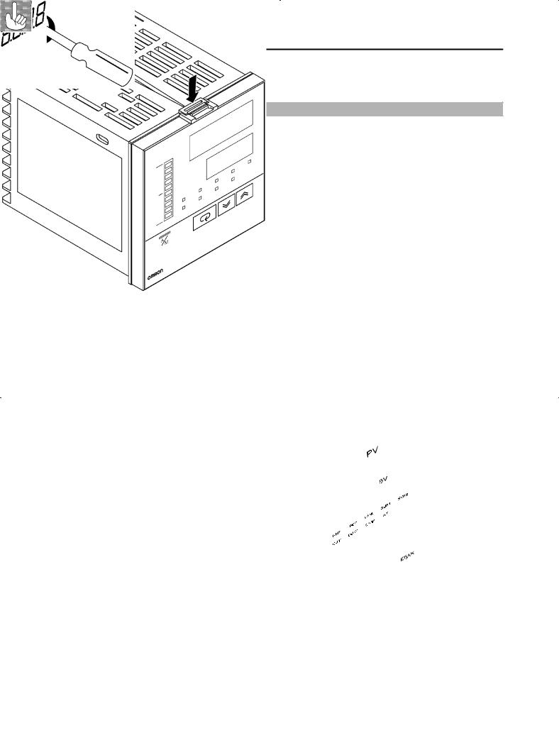
When drawing out the internal mechanism from the housing, prepare a phillips screwdriver matched to the size of the screw on the lower part of the front panel.
(1)Press down on the hook on the top of the front panel and turn the phillips screwdriver to the left to loosen the screw on the lower part of the front panel.
|
(2) Draw out the internal mechanism towards you holding both sides |
|
of the front panel. |
|
|
Fixing Screw for |
Tighten this screw by a torque of 0.3 to 0.5 N m, or approx. 3 to 5 kgf cm. |
Front Panel |
|
2--2
2.1 Setting up 

JSetting up the output unit
F Before setup |
• Check the type of the output unit you are about to set up. |
|
• For details on types of output unit and main specifications, see page |
|
2-9. |
F Procedure |
(1) Check the positions of the sockets you are about to insert the out- |
|
put units into as shown in the following diagram. |
OUT1
OUT2
Bracket
(2)Insert the output unit for control output 1 into the socket “OUT1” and the output unit for control output 2 into the socket “OUT2”.
(3)Fasten the output units with the bracket (accessory).
2--3

 CHAPTER 2 PREPARATIONS
JSetting up the option unit
F Before setup |
• Check the type of the option unit you are about to set up. |
|
• For details on types of option unit and main specifications, see Appen- |
|
dix, Model List (page A-11) and Appendix, Option Unit Ratings and |
|
Characteristics (page A-4). |
|
• For details on the relationship between units and terminals, see page |
|
2-8. |
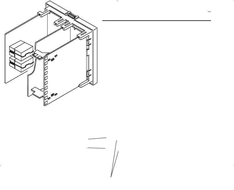
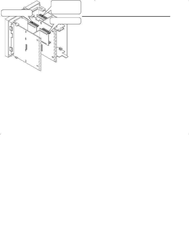
F Procedure |
(1) Remove the power board and option boards in the order shown in |
|
the following diagram. |
2
1
(2)Insert the option units into the sockets for options 1 to 3. The following diagram shows the relationship between option units and mounting positions.
|
Option 1 |
|
E53--AKB: Event inputs 1/2 |
|
E53--AK01: RS--232C |
Option 2 |
E53--AK02: RS--422 |
E53--AK03: RS--485 |
E53--AKF: Transfer output
Option 3
E53--AKB: Event inputs 3/4
(3) Mount the option boards and the power board in the order shown.
2--4

2.2 Installation
JDimensions
|
96j |
|
13.5 |
|
|
PV |
|
|
|
|
SV |
RMT |
RSP |
MANU |
SUB1 SUB2 |
OUT1 |
OUT2 |
STOP |
AT |
E5AK
JPanel cutout
110 mm min
Unit (mm)
120 mm min |
92 |
+00.8 |
|
92 +00.8
2.2 Installation 

100
j |
112 |
91 |
panel thickness is 1 to 8
specified vertical and horispace between each
must not be closely mounted horizontally.
2--5

 CHAPTER 2 PREPARATIONS
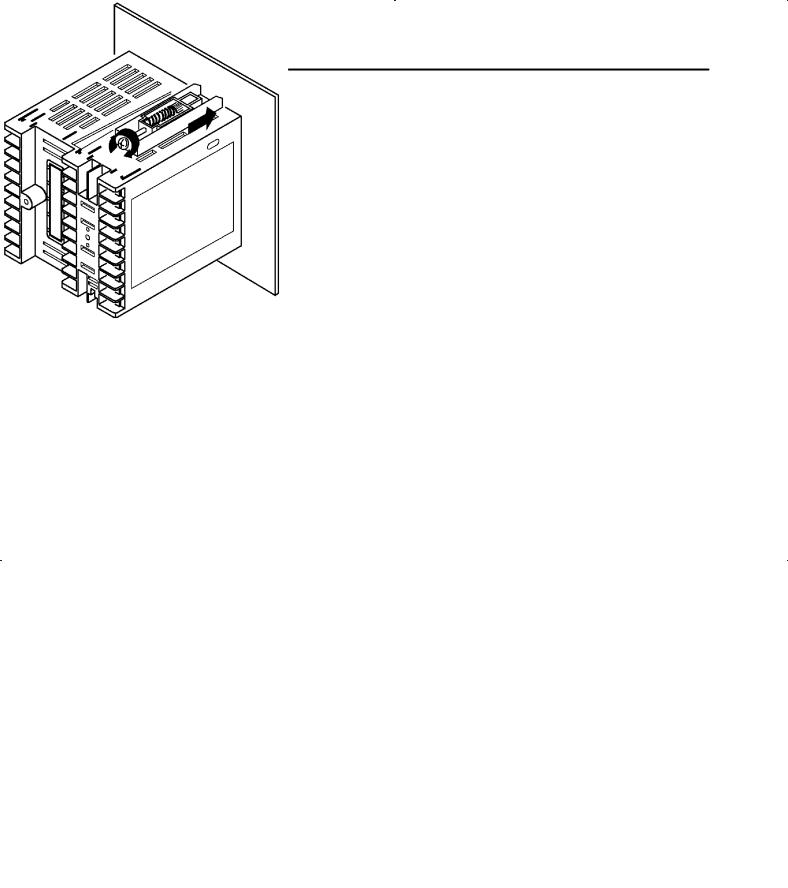
JMounting
(1)Insert the E5AK controller into the mounting hole in the panel.
(2)Fit the mounting bracket (accessory) into the fixing slots on the top and bottom of the rear case.
(3)Tighten the mounting bracket screws alternately a little at a time until the ratchet start to slide.
2--6
2.2 Installation 

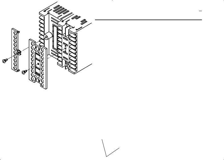
F Setting up the terminal covers
•Fasten the terminal covers (E53-COV0809) to protect terminals.
•E5AK-VV2-500 controller is provided with terminal covers.
•Use E53-COV09 for terminals 1 to 10, and E53-COV08 for terminals 11 to 33.
•Fasten the terminal covers as follows by using the snap pins.
E5AK
E53-COV0809
• To remove the terminal covers, pull the edges of the snap pins.
2--7

 CHAPTER 2 PREPARATIONS
2.3 Wiring Terminals
JTerminal arrangement
AC100-240V~ (AC/DC24V  )
)
SOURCE
OUT1
OUT2
SUB1
SUB2
10 |
TRSF |
30 |
31 32 |
20 |
|
9 |
|
29 |
|
19 |
|
8 |
|
28 |
|
18 |
|
7 |
|
27 |
|
17 |
|
6 |
|
26 |
|
16 |
|
5 |
EV3/4 |
25 |
|
15 |
|
4 |
|
24 |
|
14 |
|
3 |
|
23 |
|
13 |
|
2 |
RSP |
22 |
33 |
12 |
|
1 |
21 |
11 |
|||
|
|||||
TRSF |
: Transfer output |
|
|||
EV1 to 4 : Event inputs |
|
|
|||
PTMR |
: Potentiometer |
|
|||
EV1/2
RS232C
RS422
RS485
CT
PTMR
TC
Pt
I
V
JPrecautions when wiring
JWiring
F Power supply
10 |
30 |
31 32 |
20 |
9 |
29 |
|
19 |
8 |
28 |
|
18 |
7 |
27 |
|
17 |
6 |
26 |
|
16 |
5 |
25 |
|
15 |
4 |
24 |
|
14 |
3 |
23 |
|
13 |
2 |
22 |
33 |
12 |
1 |
21 |
11 |
•Use ducts to separate input leads and power lines in order to protect the controller and its lines from external noise.
•We recommend using solderless terminals when wiring the controller.
•Tighten the terminal screws using a torque no greater than 0.78 N·m, or 8 kgf·cm max. Take care not to tighten the terminal screws too tightly.
•Use the following type of solderless terminals for M3.5 screws.
7.2mm max.
7.2mm max.
In the following wiring diagrams, the left side of the terminal Nos. indicates the inside of the controller
•Input power to terminal Nos. 9 and 10. Power specifications are as follows:
AC100-240V , 50/60Hz, 16VA (AC/DC24V
  , 50/60Hz, 12VA, 8W)
2--8
|
|
|
|
|
|
|
|
|
2.3 |
Wiring Terminals |
|
|
|
|
|
||||||||
F Sensor input |
|
• Connect the sensor input to terminal Nos. 11 to 14 and 33 as follows |
|||||||||
10 |
30 |
31 32 |
20 |
according to the input type. |
|
|
|
|
|
||
|
|
|
|
+ |
|
|
|
||||
9 |
29 |
|
19 |
14 |
|
14 |
14 |
14 |
|
|
|
8 |
28 |
|
18 |
|
|
|
|
||||
|
13 |
|
13 |
13 |
V |
13 |
|
|
|||
7 |
27 |
|
17 |
-- |
-- |
|
|||||
|
12 |
12 |
12 |
|
12 |
|
|||||
6 |
26 |
|
16 |
-- |
|
||||||
|
11 |
|
11 |
11 |
11 |
mA |
|||||
5 |
25 |
|
15 |
+ |
|||||||
4 |
24 |
|
14 |
33 |
33 |
33 |
|
33 |
+ |
|
|
3 |
23 |
|
13 |
Thermocouple |
Platinum |
Voltage input |
Current input |
||||
2 |
22 |
|
12 |
|
|
resistance |
|
|
|
|
|
33 |
|
|
thermometer |
|
|
|
|
|
|||
1 |
21 |
11 |
|
|
|
|
|
|
|
||
|
|
|
|
|
|
|
|
||||
F Control output
10 |
30 |
31 32 |
20 |
9 |
29 |
|
19 |
8 |
28 |
|
18 |
7 |
27 |
|
17 |
6 |
26 |
|
16 |
5 |
25 |
|
15 |
4 |
24 |
|
14 |
3 |
23 |
|
13 |
2 |
22 |
33 |
12 |
1 |
21 |
11 |
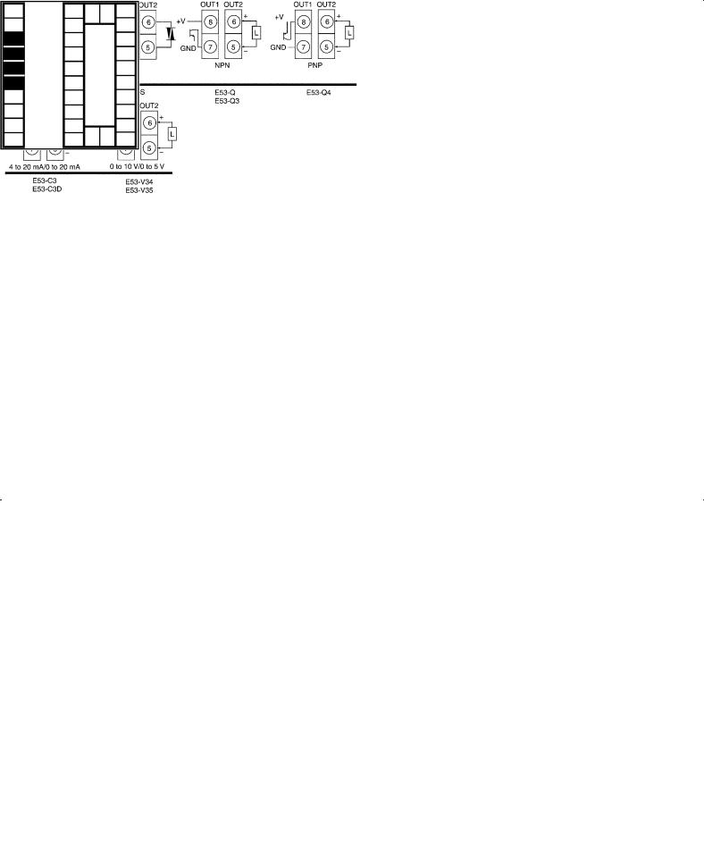
•Terminal Nos. 7 and 8 are for control output 1 (OUT1), and terminal Nos. 5 and 6 are for control output 2 (OUT2). The following diagrams show the available output units and their internal equalizing circuits.
•With E53-VVV output units, about 2 V is output for one second after the power is interrupted.
•The following table shows the specifications for each output unit.
Model |
Output Type |
Specifications |
|
|
|
E53-R |
Relay |
250 VAC, 5 A |
|
|
|
E53-S |
SSR |
75 to 250 VAC, 1 A |
|
|
|
E53-Q |
Voltage (NPN) |
NPN : 12 VDC, 40 mA (with short-circuit protection) |
E53-Q3 |
Voltage (NPN) |
NPN : 24 VDC, 20 mA (with short-circuit protection) |
E53-Q4 |
Voltage (PNP) |
PNP : 24 VDC, 20 mA (with short-circuit protection) |
|
|
|
E53-C3 |
4 to 20 mA |
4 to 20 mA, Permissible load impedance: 600 Ω max., Resolution: Approx. 2600 |
E53-C3D |
0 to 20 mA |
0 to 20 mA, Permissible load impedance: 600 Ω max., Resolution: Approx. 2600 |
|
|
|
E53-V34 |
0 to 10 V |
0 to 10 VDC, Permissible load impedance: 1 kΩ min., Resolution: Approx. 2600 |
E53-V35 |
0 to 5 V |
0 to 5 VDC, Permissible load impedance: 1 kΩ min., Resolution: Approx. 2600 |
With E5AK-PRR2 controllers, relay output (250 VAC, 1 A) is fixed.When replacing the output unit, use the E53-R. The following diagrams show the relationship between terminals and open/close relay settings.
8 |
6 |
7 |
5 |
Open |
Close |
2--9


 CHAPTER 2 PREPARATIONS
F Auxiliary output
10 |
30 |
31 32 |
20 |
9 |
29 |
|
19 |
8 |
28 |
|
18 |
7 |
27 |
|
17 |
6 |
26 |
|
16 |
5 |
25 |
|
15 |
4 |
24 |
|
14 |
3 |
23 |
|
13 |
2 |
22 |
33 |
12 |
1 |
21 |
11 |
•Terminal Nos.3 and 4 are for auxiliary output 1 (SUB1) and terminal Nos.1 and 2 are for auxiliary output 2 (SUB2).
•The internal equalizing circuits for the auxiliary outputs are as follows:
4 |
2 |
3 |
1 |
Auxiliary |
Auxiliary |
output 1 |
output 2 |
• Output specifications are as follows: SPST-NO, AC250V, 3A
F CT input/
Potentiometer
10 |
30 |
31 32 |
20 |
9 |
29 |
|
19 |
8 |
28 |
|
18 |
7 |
27 |
|
17 |
6 |
26 |
|
16 |
5 |
25 |
|
15 |
4 |
24 |
|
14 |
3 |
23 |
|
13 |
2 |
22 |
33 |
12 |
1 |
21 |
11 |
F Remote SP input
10 |
30 |
31 32 |
20 |
9 |
29 |
|
19 |
8 |
28 |
|
18 |
7 |
27 |
|
17 |
6 |
26 |
|
16 |
5 |
25 |
|
15 |
4 |
24 |
|
14 |
3 |
23 |
|
13 |
2 |
22 |
33 |
12 |
1 |
21 |
11 |
•When using the HBA function on the E5AK-AA2 controller, connect CT input (CT) to terminal Nos.15 to 17. When monitoring the valve opening on the E5AK-PRR2 controller, connect the potentiometer (PTMR) to terminal Nos.15 to 17. Connect each of these inputs as follows:
17 |
|
17 O |
16 |
CT |
16 W |
15 |
|
15 C |
CT input |
|
Potentiometer |
•For details on CT inputs, see Appendix, About Current transformer.
•For details on the potentiometer, see the Instruction Manual for the valve connected to the controller. The variable resistance range is 100 Ω to 2.5 kΩ.
•Connect an input (RSP) to be used as the remote SP to terminal Nos.21 and 22.
•Only 4 to 20 mA inputs can be connected. Connect the input as follows:
22 +
4 to 20 mA
21 --
About the power The E5AK has independent power supplies blocks for each of the terminal blocks shown on the
right.
|
A |
B |
|
|
C |
|
10 |
|
30 |
31 32 |
20 |
|
9 |
|
29 |
|
19 |
|
8 |
|
28 |
|
18 |
B 7 |
|
27 |
|
17 |
|
|
6 |
C |
26 |
|
16 |
|
5 |
25 |
|
15 |
|
E |
4 |
|
24 |
|
14 |
3 |
|
23 |
|
13 |
|
|
|
|
|||
|
2 |
|
22 |
33 |
12 |
|
1 |
|
21 |
11 |
|
|
F |
|
|
|
D |
2--10
 Loading...