


 Loading...
Cat. No. W445-E1-02
SYSMAC
CXONE-AL@@C-E
CX-Integrator Ver. 1.1
OPERATION MANUAL
CXONE-AL@@C-E
CX-Integrator Ver. 1.1
Operation Manual
Revised November 2005
iv
Notice:
OMRON products are manufactured for use according to proper procedures by a qualified operator and only for the purposes described in this manual.
The following conventions are used to indicate and classify precautions in this manual. Always heed the information provided with them. Failure to heed precautions can result in injury to people or damage to property.
!DANGER Indicates an imminently hazardous situation which, if not avoided, will result in death or serious injury. Additionally, there may be severe property damage.
!WARNING Indicates a potentially hazardous situation which, if not avoided, could result in death or serious injury. Additionally, there may be severe property damage.
!Caution Indicates a potentially hazardous situation which, if not avoided, may result in minor or moderate injury, or property damage.
OMRON Product References
All OMRON products are capitalized in this manual. The word “Unit” is also capitalized when it refers to an OMRON product, regardless of whether or not it appears in the proper name of the product.
The abbreviation “Ch,” which appears in some displays and on some OMRON products, often means “word” and is abbreviated “Wd” in documentation in this sense.
The abbreviation “PLC” means Programmable Controller. “PC” is used, however, in some Programming Device displays to mean Programmable Controller.
Visual Aids
The following headings appear in the left column of the manual to help you locate different types of information.
Note Indicates information of particular interest for efficient and convenient operation of the product.
1,2,3... 1. Indicates lists of one sort or another, such as procedures, checklists, etc.
OMRON, 2005
All rights reserved. No part of this publication may be reproduced, stored in a retrieval system, or transmitted, in any form, or by any means, mechanical, electronic, photocopying, recording, or otherwise, without the prior written permission of OMRON.
No patent liability is assumed with respect to the use of the information contained herein. Moreover, because OMRON is constantly striving to improve its high-quality products, the information contained in this manual is subject to change without notice. Every precaution has been taken in the preparation of this manual. Nevertheless, OMRON assumes no responsibility for errors or omissions. Neither is any liability assumed for damages resulting from the use of the information contained in this publication.
v
vi
TABLE OF CONTENTS
PRECAUTIONS
1 |
Intended Audience.......................................................................................................... |
xvi |
2 |
Safety Precautions.......................................................................................................... |
xvi |
3 |
Application Precautions ................................................................................................. |
xviii |
4 |
Operating Environment Precautions................................................................................ |
xx |
5 |
Guide to Version Upgrade .............................................................................................. |
xxi |
Section 1 Overview
1-1 |
The CX-Integrator ........................................................................................................ |
1-2 |
1-2 |
Specifications............................................................................................................... |
1-8 |
1-3 |
Installation.................................................................................................................. |
1-14 |
1-4 |
PLC Connecting Cables ............................................................................................ |
1-15 |
1-5 |
Window Descriptions ................................................................................................. |
1-22 |
1-6 |
Menus ........................................................................................................................ |
1-34 |
Section 2 Basic Operations
2-1 |
Basic Procedures......................................................................................................... |
2-2 |
2-2 |
Connecting Online to the Relay PLC......................................................................... |
2-10 |
2-3 |
Uploading Network Configurations and Checking for Communications Unit Errors . 2-21 |
|
2-4 |
Switching the Target PLC.......................................................................................... |
2-27 |
2-5 |
Creating Virtual Network Configurations Offline........................................................ |
2-29 |
2-6 |
Manipulating Component Parameters ....................................................................... |
2-38 |
2-7 |
Uploading, Downloading, and Comparing Network Parameters............................... |
2-43 |
2-8 |
Comparing Network Configurations........................................................................... |
2-44 |
2-9 |
File Operations .......................................................................................................... |
2-45 |
2-10 |
Target PLC Online Operations .................................................................................. |
2-49 |
2-11 |
Starting Specified Applications .................................................................................. |
2-51 |
2-12 |
Printing....................................................................................................................... |
2-52 |
Section 3 Routing Tables
3-1 |
Routing Table Overview .............................................................................................. |
3-2 |
3-2 |
Setting the Routing Tables .......................................................................................... |
3-9 |
3-3 |
Maintenance after Network Configuration ................................................................. |
3-25 |
Section 4 Data Links for Controller Link and SYSMAC LINK
4-1 |
Overview...................................................................................................................... |
4-2 |
4-2 |
User Interface Overview .............................................................................................. |
4-4 |
4-3 |
Manually Setting Data Links ........................................................................................ |
4-8 |
4-4 |
Automatically Set Data Links..................................................................................... |
4-41 |
Section 5 Ethernet
5-1 |
Broadcast Node Search .............................................................................................. |
5-2 |
5-2 |
Ping Test...................................................................................................................... |
5-4 |
vii
Section 6 DeviceNet
6-1 |
DeviceNet Setting Procedures..................................................................................... |
6-2 |
6-2 |
Setting Slave Parameters ............................................................................................ |
6-4 |
6-3 |
Adding Slaves to the Master........................................................................................ |
6-8 |
6-4 |
Setting Master Properties .......................................................................................... |
6-13 |
6-5 |
Editing Master Parameters ........................................................................................ |
6-15 |
6-6 |
Parameter Wizard ...................................................................................................... |
6-16 |
6-7 |
Master Parameter Editing Details (Tab Descriptions) ............................................... |
6-21 |
6-8 |
Manual I/O Allocations............................................................................................... |
6-29 |
6-9 |
Advanced Settings (Connection, Communication Cycle Time, Slave Function Settings, |
|
|
Etc.)............................................................................................................................ |
6-36 |
6-10 |
Creating and Editing I/O Comments .......................................................................... |
6-43 |
6-11 |
Displaying Device Properties..................................................................................... |
6-45 |
6-12 |
Downloading the Network Configuration/Device Parameters to Devices.................. |
6-51 |
6-13 |
Uploading and Verifying Device Parameters............................................................. |
6-57 |
6-14 |
Monitoring Devices .................................................................................................... |
6-62 |
6-15 |
Using General-purpose Tools to Set Devices ........................................................... |
6-70 |
6-16 |
Optional Functions ..................................................................................................... |
6-72 |
Section 7 CompoWay/F
7-1 |
CompoWay/F System Configuration ........................................................................... |
7-2 |
7-2 |
CompoWay/F Slaves Connected to a PLC ................................................................. |
7-3 |
7-3 |
CompoWay/F Slaves Connected to a Computer....................................................... |
7-10 |
Section 8 NT Links
8-1 |
NT Link Connection Auto-detect Function................................................................... |
8-2 |
8-2 |
Transferring Screen Data through the PLC ................................................................. |
8-6 |
Section 9 Network Testing
9-1 |
Controller Link Network Diagnostic Tool |
...................................................................... 9-2 |
9-2 |
Echoback Test between Nodes ................................................................................. |
9-22 |
9-3 |
Ethernet Ping Test ..................................................................................................... |
9-25 |
Appendices
A-1 |
CPS File Management................................................................................................. |
A-2 |
A-2 |
EDS File Management................................................................................................. |
A-4 |
Revision History
viii

About this Manual:
This manual describes the installation and operation of CX-Integrator and includes the sections described below.
Please read this manual carefully and be sure you understand the information provided before attempting to use the CX-Integrator. Be sure to read the precautions provided in the following section.
Precautions provides general precautions for using the CX-Integrator.
Section 1 outlines the functions of the CX-Integrator and describes the menus and connecting to networks.
Section 2 describes the basic operations required to use the CX-Integrator.
Section 3 describes how to set routing tables.
Section 4 describes how to set data links for Controller Link and SYSMAC LINK Networks.
Section 5 describes the how to use the diagnostic tools for Controller Link Networks.
Section 6 describes settings and operations unique to DeviceNet Networks, including registering slaves in the master, allocating I/O, monitoring devices, etc.
Section 7 describes settings and operations unique to CompoWay/F Networks.
Section 8 settings and operations unique to NT Links.
The Appendix describes CPS files for Ethernet, Controller Link, CompoWay/F, and NT Link Networks and EDS files for DeviceNet Networks.
!WARNING Failure to read and understand the information provided in this manual may result in personal injury or death, damage to the product, or product failure. Please read each section in its entirety and be sure you understand the information provided in the section and related sections before attempting any of the procedures or operations given.
ix
Manuals Related to the CX-Integrator
Cat No. |
Models |
Name |
Description |
W445 |
CXONE-AL@@C-E |
CX-Integrator Operation |
Describes CX-Integrator operating |
(this manual) |
|
Manual |
methods, e.g., for setting up and |
|
|
|
monitoring networks. |
W444 |
CXONE-AL@@C-E |
CX-One Setup Manual |
Describes installation and provides an |
|
|
|
overview of the CX-One FA Integrated |
|
|
|
Tool Package. |
W446 |
WS02-CXPC1-E-V60 |
CX-Programmer Ver. 6.1 |
Describes CX-Programmer operations |
|
|
Operation Manual |
except those related to function blocks. |
W447 |
WS02-CXPC1-E-V60 |
CX-Programmer Ver. 6.1 |
Describes function blocks for |
|
CS1G-CPU@@H |
Operation Manual: |
CS/CJ-series CPU Units unit version 3.0 |
|
CS1H-CPU@@H |
Function Blocks |
or later and CP-series CPU Units, and |
|
CJ1GCPU@@H |
|
CX-Programmer operations related to |
|
|
function blocks. |
|
|
CJ1HCPU@@H |
|
|
|
|
Refer to the W447 manual above for other |
|
|
CJ1MCPU@@ |
|
|
|
|
CX-Programmer operations. |
|
|
CP1H- X@@@@-@ |
|
|
|
|
|
|
|
CP1H- XA@@@@-@ |
|
|
Manuals Related to DeviceNet
Cat No. |
Models |
Name |
Description |
W267 |
--- |
DeviceNet Operation |
Describes network communications |
|
|
Manual |
settings and wiring common to all |
|
|
|
DeviceNet networks. |
W380 |
CS1W-DRM21(-V1) |
DeviceNet Unit Operation |
Describes CX/CJ-series DeviceNet Units. |
|
CJ1W-DRM21 |
Manual |
|
W379 |
C200HW-DRM21-V1 |
DeviceNet Master Unit |
Describes C200H and CV/CVM1-series |
|
CVM1-DRM21-V1 |
Operation Manual |
DeviceNet Master Units. |
W381 |
3G8F7-DRM21 |
DeviceNet PCI Board |
Describes the DeviceNet PCI Board. |
|
|
Operation Manual |
|
x

Read and Understand this Manual
Please read and understand this manual before using the product. Please consult your OMRON representative if you have any questions or comments.
Warranty and Limitations of Liability
WARRANTY
OMRON's exclusive warranty is that the products are free from defects in materials and workmanship for a period of one year (or other period if specified) from date of sale by OMRON.
OMRON MAKES NO WARRANTY OR REPRESENTATION, EXPRESS OR IMPLIED, REGARDING NON-INFRINGEMENT, MERCHANTABILITY, OR FITNESS FOR PARTICULAR PURPOSE OF THE PRODUCTS. ANY BUYER OR USER ACKNOWLEDGES THAT THE BUYER OR USER ALONE HAS DETERMINED THAT THE PRODUCTS WILL SUITABLY MEET THE REQUIREMENTS OF THEIR INTENDED USE. OMRON DISCLAIMS ALL OTHER WARRANTIES, EXPRESS OR IMPLIED.
LIMITATIONS OF LIABILITY
OMRON SHALL NOT BE RESPONSIBLE FOR SPECIAL, INDIRECT, OR CONSEQUENTIAL DAMAGES, LOSS OF PROFITS OR COMMERCIAL LOSS IN ANY WAY CONNECTED WITH THE PRODUCTS, WHETHER SUCH CLAIM IS BASED ON CONTRACT, WARRANTY, NEGLIGENCE, OR STRICT LIABILITY.
In no event shall the responsibility of OMRON for any act exceed the individual price of the product on which liability is asserted.
IN NO EVENT SHALL OMRON BE RESPONSIBLE FOR WARRANTY, REPAIR, OR OTHER CLAIMS REGARDING THE PRODUCTS UNLESS OMRON'S ANALYSIS CONFIRMS THAT THE PRODUCTS WERE PROPERLY HANDLED, STORED, INSTALLED, AND MAINTAINED AND NOT SUBJECT TO CONTAMINATION, ABUSE, MISUSE, OR INAPPROPRIATE MODIFICATION OR REPAIR.
xi
Application Considerations
SUITABILITY FOR USE
OMRON shall not be responsible for conformity with any standards, codes, or regulations that apply to the combination of products in the customer's application or use of the products.
At the customer's request, OMRON will provide applicable third party certification documents identifying ratings and limitations of use that apply to the products. This information by itself is not sufficient for a complete determination of the suitability of the products in combination with the end product, machine, system, or other application or use.
The following are some examples of applications for which particular attention must be given. This is not intended to be an exhaustive list of all possible uses of the products, nor is it intended to imply that the uses listed may be suitable for the products:
•Outdoor use, uses involving potential chemical contamination or electrical interference, or conditions or uses not described in this manual.
•Nuclear energy control systems, combustion systems, railroad systems, aviation systems, medical equipment, amusement machines, vehicles, safety equipment, and installations subject to separate industry or government regulations.
•Systems, machines, and equipment that could present a risk to life or property.
Please know and observe all prohibitions of use applicable to the products.
NEVER USE THE PRODUCTS FOR AN APPLICATION INVOLVING SERIOUS RISK TO LIFE OR PROPERTY WITHOUT ENSURING THAT THE SYSTEM AS A WHOLE HAS BEEN DESIGNED TO ADDRESS THE RISKS, AND THAT THE OMRON PRODUCTS ARE PROPERLY RATED AND INSTALLED FOR THE INTENDED USE WITHIN THE OVERALL EQUIPMENT OR SYSTEM.
PROGRAMMABLE PRODUCTS
OMRON shall not be responsible for the user's programming of a programmable product, or any consequence thereof.
xii

Disclaimers
CHANGE IN SPECIFICATIONS
Product specifications and accessories may be changed at any time based on improvements and other reasons.
It is our practice to change model numbers when published ratings or features are changed, or when significant construction changes are made. However, some specifications of the products may be changed without any notice. When in doubt, special model numbers may be assigned to fix or establish key specifications for your application on your request. Please consult with your OMRON representative at any time to confirm actual specifications of purchased products.
DIMENSIONS AND WEIGHTS
Dimensions and weights are nominal and are not to be used for manufacturing purposes, even when tolerances are shown.
PERFORMANCE DATA
Performance data given in this manual is provided as a guide for the user in determining suitability and does not constitute a warranty. It may represent the result of OMRON's test conditions, and the users must correlate it to actual application requirements. Actual performance is subject to the OMRON Warranty and Limitations of Liability.
ERRORS AND OMISSIONS
The information in this manual has been carefully checked and is believed to be accurate; however, no responsibility is assumed for clerical, typographical, or proofreading errors, or omissions.
xiii
xiv
PRECAUTIONS
This section provides precautions for using the CX-Integrator.
The information contained in this section is important for the safe and reliable application of the CX-Integrator. You must read this section and understand the information contained before attempting to use the CX-Integrator.
1 |
Intended Audience.......................................................................................... |
xvi |
2 |
Safety Precautions .......................................................................................... |
xvi |
3 |
Application Precautions.................................................................................. |
xviii |
4 |
Operating Environment Precautions............................................................... |
xx |
5 |
Guide to Version Upgrade.............................................................................. |
xxi |
1 Intended Audience
1 Intended Audience
This manual is intended for the following personnel, who must also have knowledge of electrical systems (an electrical engineer or the equivalent).
•Personnel in charge of installing FA systems
•Personnel in charge of designing FA systems
•Personnel in charge of managing FA systems and facilities
2 Safety Precautions
!Caution When performing any of the following operations, always check the network address and node address of the other node (PLC) and the node address and unit number of the mounted Unit (PLC CPU Bus Unit or Special I/O Unit) or the node address of the Component (DeviceNet Master/Slave or CompoWay/F Slave), and be sure that these operations can be performed safely for the current status of the node (Unit or Component):
•Transferring parameter or program data to the other node
•Changing the operating mode of the other node
Unexpected operation may result if parameter or program data is transferred to the wrong node (DeviceNet Master/Slave or CompoWay/F Slave), the operating mode of the wrong node is changed, or the other node is not in a suitable status to receive the program or parameter data or the operating mode change.
!Caution When changing the target PLC to any PLC other than the relay PLC, check the node address and node number of the target PLC carefully before executing the change. Unexpected operation and injury may result if the wrong PLC is set as the target PLC.
•Changing the operating mode
•Transferring or verifying user-set data link tables
•Transferring or verifying routing tables
•Performing I/O table operations (including transferring CPU Bus Unit or Special I/O Unit parameters)
Note Operations performed from the CX-Integrator are performed for the target PLC, which is not necessarily the same as the relay PLC.
!Caution When transferring parameters that have been created or edited on the computer to actual Units (PLC CPU Bus Units or PLC Special I/O Units) or to actual Components (DeviceNet Masters/Slaves or CompoWay/F Slaves), always check the identifying number of the actual Units or Components (i.e., the unit numbers and unit addresses or node addresses) before executing the transfer. Unexpected operation and injury may result if parameters are transferred to the wrong Unit or Component.
!Caution When changing or removing a routing table (see note), be sure to update the display for the Online Connection Information Window. The display for the Online Connection Information Window could possibly be different from the actual network status. If operations are executed without first updating the display, particularly online operations in the Network Configuration Window, it could cause data to be mistakenly read or written for the wrong network or node address or unit number.
xvi
2 Safety Precautions
Note: Changing or removing a routing table refers to using the CX-Integrator (or a CX-Integrator for another personal computer) to start the Routing Table Component and then changing or removing a routing table for the target PLC (either a local network table or a relay network table).
!Caution Do not execute a broadcast node search if a node exists for something other than an OMRON Ethernet Unit or FinsGateway within the same segment on Ethernet, and when the Ethernet network system is in operation. When a broadcast node search is executed, an OMRON FINS command is sent to all nodes in the segment. Therefore, if a node exists for something other than an OMRON Ethernet Unit or FinsGateway, the FINS command will not be received at that node and unexpected operation may occur.
xvii
3 Application Precautions
3 Application Precautions
Observe the following precautions when using the CX-Integrator.
General Communications Precautions
•Do not turn OFF the power to the PLC or disconnect the cable connecting the PLC when the CX-Integrator is online with the PLC. Doing so may cause the computer running CX-Integrator to malfunction.
•Before changing the operating mode, always confirm that doing so will not adversely affect system operation.
•Always check the operation of parameters sufficiently before using them for actual system operation.
•Confirm that resetting CPU Bus Units and Special I/O Units will not adversely affect system operation before resetting these Units.
DeviceNet
•Enable the scan list to before operating the system.
•When adding a new node to the network, make sure that the baud rate is the same as other nodes.
•Use specified communications cables.
•Do not extend connection distances beyond the ranges given in the specifications.
•Always turn OFF the power supply to the personal computer, Slaves, and Communications Units before attempting any of the following.
•Attaching or detaching the DeviceNet Board or Card
•Assembling the Units
•Setting rotary switches
•Connecting or wiring the cables
•Connecting or disconnecting connectors
•Be sure that the communications cables and other items with locking devices are properly locked into place.
•Observe the following precautions when wiring the communications cable.
•Separate the communications cables from the power lines or high-tension lines.
•Do not bend the communications cables.
•Do not pull on the communications cables.
•Do not place heavy objects on top of the communications cables.
•Be sure to wire communications cable inside ducts.
•Use appropriate communications cables.
•Before touching the PCI Board, be sure to first touch a grounded metallic object in order to discharge any static build-up. Not doing so may result in malfunction or damage.
•When transporting a Board or Card, use the special box in which it was shipped to protect the LSIs and ICs from being damaged. Also do not subject the Board or Card to excessive vibration or shock.
xviii
3 Application Precautions
•Because the devices are reset in order, communications errors will temporarily occur in the master and slaves. For this reason, do not download the network configuration while the master-side PLC (CPU Unit) is operating.
•When downloading the network configuration, each of the devices is reset. If the Master Unit is reset first, it may cause errors in writing parameters to the subsequent slaves. For that reason, this method (downloading the network configuration) should be used only when the Master Unit has been given the highest address.
•Downloaded device parameters will be valid only after the devices are reset unless they are the OMRON CVM1-DRM21-V1, C200HW-DRM21-V1, CS1W-DRM21(-V1), or CJ1W-DRM21.
•When the devices are reset, communications errors will temporarily occur. For this reason, do not reset the devices while the master-side PLC (CPU Unit) is operating.
Data Links in Controller Link or SYSMAC LINK Networks
•The data link mode (manual setting or automatic setting) and data link method are determined according to the data link setting in the startup node. In the startup node, set a data link table for manual settings and data link automatic setting parameters for automatic settings. If the settings are incorrect, the data links will not start.
Check the following items before starting data links.
(1)Manually Set Data Links
Check the data link tables in each node participating in the data link to see that they are correct.
Be sure that data link tables are deleted from nodes that are not participating in the data links.
(2)Automatically Set Data Links
Be sure that the correct DM parameters have been set in the data link startup node.
•If incorrect data link tables or parameters are set, injury may result due to unexpected operation of the system. Even if the correct data link tables and parameters have been set, do not start or stop data links before verifying that there will be no adverse influence on the system.
Routing Tables
CPU Bus Units are reset when routing tables are transferred from a Programming Device to a PLC to allow set routing tables to be read. Make sure that resetting CPU Bus Units will not cause equipment damage or dangerous system behavior before transferring tables.
xix
4 Operating Environment Precautions
4 Operating Environment Precautions
!Caution Perform installation properly, according to the procedures described in this manual.
!Caution Do not install in the following locations:
•Locations subject to direct sunlight
•Locations subject to temperatures or humidity outside the range specified in the specifications
•Locations subject to condensation as the result of severe changes in temperature
•Locations subject to corrosive or flammable gases
•Locations subject to dust (especially iron dust) or salts
•Locations subject to exposure to water, oil, or chemicals
•Locations subject to shock or vibration
!Caution Take appropriate and sufficient countermeasures when installing in the following locations:
•Locations subject to static electricity or other forms of noise
•Locations subject to strong electromagnetic fields
•Locations subject to possible exposure to radioactivity
•Locations close to power supplies
xx
5 Guide to Version Upgrade
5 |
|
Guide to Version Upgrade |
|
|
|||
|
|
|
|
The following table shows the changes in the upgrade from CX-Integrator |
|||
|
|
|
|
Ver. 1.0 to Ver. 1.1. |
|
|
|
|
|
|
|
|
|
|
|
|
Item |
|
|
|
Previous (Ver. 1.0) |
Ver. 1.1 |
|
|
|
|
|
|
|
||
|
CP1H supported as PLC model |
No |
Yes |
|
|||
|
|
|
|
|
|
|
|
|
Automatic |
|
Automatic |
No |
Yes. When Automatic USB |
|
|
|
online |
|
USB |
|
Connection is selected from the |
||
|
connection |
|
connection |
|
Network Menu, the PLC model |
|
|
|
|
|
|
|
|
(such as the CP1H) is |
|
|
|
|
|
|
|
automatically recognized and |
|
|
|
|
|
|
|
connected online. |
|
|
|
|
|
|
|
||
|
Ethernet network PING test |
No |
Yes |
|
|||
|
|
|
|
|
|||
|
Echoback test between nodes |
No |
Yes. (Response time can be |
|
|||
|
on |
Ethernet, |
Controller Link, |
|
measured.) |
|
|
|
SYSMAC LINK, and DeviceNet |
|
|
|
|||
|
|
|
|
|
|||
|
Controller Link network |
No |
Branching information can |
be |
|||
|
diagnosis Repeater display |
|
displayed by Repeater Units. |
|
|||
|
|
|
|
||||
|
Start Special Application |
No |
It is possible to select an Inverter |
||||
|
|
|
|
|
|
on DeviceNet, and to start |
the |
|
|
|
|
|
|
CX-Drive. |
|
|
|
|
|
|
|||
|
Support for NSJ Series |
No |
Yes |
|
|||
|
|
|
|
|
|
|
|
xxi
Communications
Section 1 Overview
This section provides an overview of the CX-Integrator and describes CX-Integrator menus and connections.

1-1 The CX-Integrator
1-1-1 Overview
1-1 The CX-Integrator
1-1-1 Overview
The CX-Integrator is a Programming Device software package that enables reading the PLC's network and serial network configuration from a personal computer via an online connection. This enables easily performing many operations, such as monitoring the connection status of various networks, setting parameters, and diagnosing networks.
The CX-Integrator can be placed online manually or automatically with the CS/CJ-series PLC to which it is directly connected to enable uploading and monitoring the network configuration (including device parameters) for that PLC or other network PLCs for each network.
Direction connection to serial communications using the CompoWay/F protocol is also possible without going through a PLC. The CompoWay/F network configuration can be uploaded or automatic connection is possible using the NT Link protocol for NS-series PTs and CS/CJ-series PLCs.
Furthermore, parameters in slaves on the networks can be set, edited, uploaded, and downloaded.
Whenever required, network configuration information can be saved in files. The configuration information in previously saved files can be later compared to the actually current configuration.
Uploading and displaying network and serial communications configuration of the target PLC for each network
CS/CJ-series PLC
Computer running CX-Integrator
Ethernet
Target PLC
CS/CJ-series PLC
Online connection
|
|
|
Serial |
Access |
|
|
connection |
|
|
(NT Link) |
Direct serial connection |
|
|
|
(Toolbus or Host Link) or |
Controller Link |
|
|
network connection |
|
|
|
|
DeviceNet |
|
|
Uploaded to computer |
General-purpose slaves, |
|
|
|
PLC |
Temperature Controller |
|
|
such as I/O Terminals |
||
|
CompoWay/F |
|
or other device |
|
|
|
|
Serial communications/net works that can be accessed
|
|
|
|
|
|
|
|
|
|
|
|
|
|
|
|
|
|
|
|
|
|
|
|
|
|
|
|
|
|
|
|
|
|
|
|
|
|
|
|
|
|
|
|
|
|
Temperature |
Smart Sensor |
||||||
Controller |
||||||||
|
|
|
|
|||||
1-2
1-1 The CX-Integrator
1-1-1 Overview
The network/serial communications configuration of a PLC other than the one originally connected to online to can be set as the target. The PLC that was originally connected to online (called the relay PLC, see note 1), is relayed through to connect to another PLC (called the target PLC, see note 2) to switch the online connection.
Note 1: The relay PLC is the PLC to which an online connection was first made from the computer through a network or serial connection.
Note 2: The target PLC is the PLC from which the network configuration can be uploaded.
Uploading and displaying network and serial |
|
|
|
|
|
|
|
|
|
CS/CJ-series PLC |
|||||
|
|
|
|
|
|
|
|
|
|||||||
communications configuration of the target PLC for each |
|
|
|
|
|
|
|
|
|
||||||
network |
A PLC other than the relay PLC |
|
|
|
|
|
|
|
|
|
|
|
|
|
|
Computer running |
|
|
|
|
|
|
|
|
|
|
|
|
|
||
|
|
|
|
|
|
|
|
|
|
|
|
||||
can be set as the target. |
|
|
|
|
|
|
|
|
|
|
|
|
|
|
|
CX-Integrator |
|
|
|
|
|
|
|
|
|
|
|
||||
|
|
|
|
|
|
|
|
|
|
|
|
|
|
|
|
|
|
|
|
|
|
|
|
|
|
|
|
|
|
|
|
|
|
Ethernet |
|
|
Relay PLC |
Target PLC |
|
|
CS/CJ-series PLC |
CS/CJ-series |
|
Online |
PLC |
||
|
|||
connection |
|
|
|
|
|
|
|
|
|
|
|
|
|
|
|
|
Serial connection |
Access |
|
|
|
|
|
|
|
|
|
|
|
|
|
(NT Link) |
|
|
|
|
|
|
|
|
|
|
|
|
|
||
|
|
|
|
|
|
|
|
|
|
|
|
|
||
Direct serial connection |
|
|
|
|
|
|
|
|
|
|
|
|
|
|
|
|
|
|
|
|
|
|
|
|
|
|
|
|
|
(Toolbus or Host Link) or |
|
|
|
|
|
Controller Link |
||||||||
network connection |
|
|
|
|
|
|||||||||
|
|
|
|
|
|
|
|
|
|
|
|
|
|
|
DeviceNet |
|
|
|
Uploaded to computer |
|
|
|
General-purpose slaves, |
PLC |
Temperature |
|
such as I/O Terminals |
|||
|
Controller or |
||
|
|
||
CompoWay/F |
|
other device |
Serial communications/net works that can be accessed
Temperature |
Smart Sensor |
Controller |
Direction connection from the CX-Integrator to serial communications using the CompoWay/F protocol is also possible using RS-232C or RS-485 communications without going through a PLC. The CompoWay/F network configuration can also be uploaded.
Computer running
CX-Integrator
Standard RS-232C cable (female-female)
K3SC RS-232C to RS-485 Interface
Converter
|
RS-485 cable connection |
|
|
|
CompoWay/F protocol |
|
|
Uploaded to computer |
Temperature |
Smart Sensor |
|
|
Smart Sensor |
||
|
Controller |
||
|
|
||
1-3
1-1 The CX-Integrator
1-1-2 Functions According to Network
1-1-2 Functions According to Network
The functions for each network are listed in the following table.
Network |
Functions |
DeviceNet or CompoWay/F |
A virtual network or virtual serial communications |
|
configuration can be created offline and connected |
|
device parameters can be set, uploaded, |
|
downloaded, and compared. |
Controller Link or SYSMAC LINK |
User-set data link tables can be created offline |
|
and then transferred online to CS/CJ-series PLCs. |
|
Data link parameters can be set automatically |
|
online and then transferred to CS/CJ-series PLCs. |
Controller Link |
A Controller Link Network Diagnostic Tool can be |
|
started to diagnose Controller Link networks. |
Ethernet |
Broadcast node searches and ping tests are |
|
enabled (with CX-Integrator Ver. 1.1 or later). |
NT Link |
Settings for an NS-series PT with a model number |
|
ending in V1 or later serially connected to a |
|
CS/CJ-series PLC via NT Link can be |
|
automatically detected and set for the serial port of |
|
the CS/CJ-series PLC. This is called NT Link Auto |
|
Online Setting function. |
FINS networks, such as Ethernet, Controller |
Routing tables can be set offline and then |
Link, SYSMAC LINK, and DeviceNet |
transferred online to CS/CJ-series PLCs. |
|
Echoback tests between nodes are enabled (with |
|
CX-Integrator Ver. 1.1 or later). |
1-1-3 Connecting to the Relay PLC
Either of the following methods can be used to connect the CX-Integrator online to the relay PLC.
Serial communications (Toolbus or Host Link Mode)
FINS network communications, such as Controller Link, SYSMAC LINK, Ethernet, Ethernet FINS/TCP, or FinsGateway
Note: If the computer running the CX-Integrator is connected directly to a network, the network address and node can be specified to set any PLC on the local network or an interconnected network as the relay PLC.
1-4
1-1 The CX-Integrator
1-1-4 Accessible Network
1-1-4 Accessible Network
The network configuration of the target PLC (i.e., either the relay PLC or a PLC connected to the relay PLC) can be uploaded and monitored for each of the following networks.
Accessible Networks
|
Network |
Conditions |
|
Ethernet |
Monitoring and editing parameters is possible for all CS/CJ-series PLCs |
|
|
and NSJ-series NSJ Controllers on the Ethernet network. Only monitoring |
|
|
the network configuration is possible for CVM1/CV-series PLCs and |
|
|
computers with FinsGateway. |
|
Controller Link |
Monitoring and editing parameters is possible for all CS/CJ-series PLCs |
|
|
and NSJ-series NSJ Controllers on the Controller Link network. Only |
|
|
monitoring the network configuration is possible for C200HX/HG/HS |
|
|
PLCs, CVM1/CV-series PLCs, and computers with FinsGateway. |
|
SYSMAC LINK |
Monitoring and editing parameters is possible for all CS-series PLCs on |
|
|
the SYSMAC LINK network. Only monitoring the network configuration is |
|
|
possible for C200HX/HG/HS PLCs, CVM1/CV-series PLCs, and |
|
|
computers with FinsGateway. |
|
DeviceNet |
Monitoring and editing parameters is possible for all CS/CJ-series |
|
|
DeviceNet Units and NSJ-series NSJ Controllers. Only setting the |
|
|
DeviceNet Master Unit is possible for C200H-series DeviceNet Master |
|
|
Unit and CVM1/CV-series DeviceNet Master Units. |
Accessible Serial Communications |
||
Serial |
|
Conditions |
communications |
|
|
CompoWay/F |
The serial communications mode of the serial port must be Serial |
|
|
Gateway Mode or Protocol Macro Mode. (See note.) |
|
|
Note: |
To use the built-in serial ports on CS/CJ-series CPU Units, |
|
unit version 3.0 or later must be used. For Serial Communications |
|
|
Boards and Serial Communications Units, unit version 1.2 or later |
|
|
must be used. |
|
|
Monitoring and parameter editing is possible only for CompoWay/F slaves |
|
|
for which CPS files have been installed on the computer running the |
|
|
CX-Integrator. |
|
|
(If the CompoWay/F slave is a Temperature Controller, however, only |
|
|
monitoring the network configuration is possible. Parameters are edited |
|
|
using the CX-Thermo.) |
|
NT Link |
The serial communications mode of the serial port must be 1:N NT Link. |
|
|
Monitoring is possible only for NS-series PTs with model numbers ending |
|
|
in V1or later. (Monitoring is not possible for earlier NS-series PTs without |
|
|
a model number suffix or for NT-series PTs.) |
|
1-5
1-1 The CX-Integrator
1-1-4 Accessible Network
Local Network Table Requirements
A local network table must be registered in the target PLC in the following cases.
Communications |
|
Conditions |
Network |
• More than one Network Communications Unit is mounted to the target |
|
communications |
PLC. (See note.) |
|
|
Note: |
Network Communications Units include Ethernet Units, Controller |
|
Link Units, SYSMAC LINK Units, DeviceNet Units, and FL-net Units. |
|
|
Serial Communications Units and Serial Communications Boards are not |
|
|
included except in the following case: If serial ports are registered in the |
|
|
local network table to treat them as networks, the serial ports must be |
|
|
treated as Network Communications Units, including the serial ports on |
|
|
the CPU Unit. |
|
|
• Routing tables are already registered in one or more nodes on the network. |
|
|
• Communications are required between networks. |
|
Serial |
Serial ports on Serial Communications Units and Serial Communications |
|
communications |
Boards are used as serial gateways to Host Link FINS and access is |
|
|
required via networks via Host Link FINS to PLCs functioning as Host Link |
|
|
slaves. |
|
|
Note: |
Serial ports do not necessarily need to be registered in the local |
|
network table (to treat them as networks) to enable using other serial |
|
|
gateway functions. Registration is normally not required to convert from |
|
|
serial to serial. Refer to 3-6 Overview of Serial Gateway Functions in the |
|
|
CS/CJ-series Communications Commands Reference Manual (Cat. No. |
|
|
W342) for details on whether local network tables are required to use |
|
|
serial gateway functions. |
|
Note: As an exception, local network tables are not required even when more than one Network Communications Unit is mounted in the following situation:
Access is possible without a local network table when connecting online to the target PLC via a direct serial connection and access is required only to the network of the Network Communications Unit with the smallest unit number (set on the front panel rotary switches) of all the Network Communications Units that are mounted to the target PLC.
1-6

1-1 The CX-Integrator
1-1-5 Communicating Across Network Layers
1-1-5 Communicating Across Network Layers
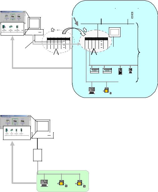
If relay network routing tables are set in the CPU Units of the PLCs, a PLC on a different network layer than the network of the PLC connected to the CX-Integrator can be set as the target PLC to enable uploading, saving, and comparing the network configuration of the target PLC.
Uploading and displaying network and serial communications configuration of a target PLC on a remote network for each network
Computer running
CX-Integrator
 Relay network routing tables
 set in the CPU Units
Relay PLC
|
CS/CJ-series PLC |
CS/CJ-series PLC |
Target PLC |
|
|
|
|
|
|
|
|
Serial connection |
|
|
|
|
|
(Toolbus or Host |
|
|
CS/CJ-series PLC |
|
|
Link) or network |
|
|
|
Serial connection |
|
connection |
Controller Link |
|
|||
|
|
(NT Link) |
|
||
|
|
|
|
|
|
|
|
Ethernet |
|
|
Network and serial |
|
|
|
|
|
communications |
|
|
|
|
|
structure can be |
|
|
|
|
|
uploaded. |
Uploaded to computer |
|
DeviceNet |
|
|
|
|
|
|
|
|
Temperature |
|
|
|
General-purpose slaves, such |
Controller or |
|
|
|
|
other device |
||
|
|
|
as I/O Terminals |
PLC |
|
|
|
|
|
||
1-1-6 Starting Other Applications
The following applications can be started from the CX-Integrator.
Application |
Starting method |
CX-Programmer |
Right-click the desired CS/CJ-series PLC in the Network |
|
Configuration Window and select Start Special Application |
|
from the pop-up menu. |
Data Link Component |
Either select Tools – Start Data Link or right-click the desired |
|
Controller Link Unit in the Online Connection Information |
|
Window and select Start Data Link from the pop-up menu. |
Routing Table Component |
Either select Tools – Start Routing table or right-click the |
|
desired Communication Unit/port in the Online Connection |
|
Information Window and select Start Routing table from the |
|
pop-up menu. |
Controller Link Network Diagnostic |
Select Tools – Controller Link tool – Network diagnosis. |
Tool |
|
CX-Designer |
Right-click the desired NS-series PT in the Network |
|
Configuration Window and select Start Special Application |
|
from the pop-up menu. |
CX-Thermo |
Right-click the desired OMRON Temperature Controller in the |
|
Network Configuration Window and select Start Special |
|
Application from the pop-up menu. |
CX-Drive |
Right-click the desired Inverter or Servo in the Network |
|
Configuration Window and select Start Special Application |
|
from the pop-up menu. |
1-7

1-2 Specifications
1-2-1 CX-Integrator Specifications
1-2 Specifications
1-2-1 CX-Integrator Specifications
Item |
|
|
|
Specification |
|
Model |
|
Provided in the CX-One FA Integrated Tool Package (CXONE-AL@@C-E). |
|||
Setup media |
|
CD-ROM |
|
|
|
Applicable |
Computer |
IBM PC/AT or compatible |
|
||
computers |
CPU |
Pentium II, 333 MHz or better, for Windows 98 SE or NT 4.0 with service pack 6a Pentium III, 1 |
|||
(with |
|
GHz or better, is recommended. |
|||
FinsGateway) |
OS |
Microsoft Windows 98 SE, Me, 2000, or XP |
|||
|
|
Microsoft Windows NT version 4.0 service pack 6a |
|||
|
|
Note: CX-Integrator cannot be used with Windows 95. |
|||
|
Memory |
64 MB min. for Windows 98 SE or NT 4.0 with service pack 6a |
|||
|
Hard disk |
100 MB min. of available space |
|
||
|
drive |
|
|
|
|
|
Monitor |
SVGA, 800 x 600 pixels or better |
|||
|
|
Note: Use the small font size. |
|
||
|
CD-ROM |
At least one required. |
|
||
|
drive |
|
|
|
|
|
Communi |
At least one RS-232C or USB port (See note.) |
|||
|
cations |
Note: |
The USB port on a computer can be connected to if the CJ1W-CIF31 USB-Serial |
||
|
port |
Conversion Cable is used. (The driver software included with the CJ1W-CIF31 must be installed |
|||
|
|
on the computer.) |
|
||
PLCs that can be used |
Series |
Device type |
CPU Unit model |
||
as relay PLC for online |
|
|
(See note 1.) |
|
|
connections |
|
CS Series |
|
CS1H |
CS1H-CPU67/66/65/64/63(-V1) |
|
|
|
|
|
|
Note: A relay PLC is the |
|
|
CS1G/CJ1G |
CS1G-CPU45/44/43/42(-V1) |
|
|
|
|
|
||
|
|
CS1G-H |
CS1G-CPU45H/44H/43H/42H |
||
PLC to which the |
|
|
|||
|
|
CS1H-H |
CS1H-CPU67H/66H/65H/64H/63H |
||
CX-Integrator is |
|
|
|||
|
|
CS1D-H |
CS1D-CPU67H/65H (See note 2.) |
||
connected online. |
|
|
|||
|
|
|
|
CS1D-S |
CS1D-CPU67S/65S/44S/42S |
|
|
CJ Series |
|
CS1G/CJ1G |
CJ1G-CPU45/44 |
|
|
|
|
CJ1M |
CJ1M-CPU23/22/21/13/12/11 |
|
|
|
|
CJ1G-H |
CJ1GCPU45H/44H/43H/42H |
|
|
|
|
CJ1H-H |
CJ1H-CPU67H/66H/65H |
|
|
CP-Series |
|
CP1H-XA |
CP1H-XA@@@@-@ |
|
|
(See note 3.) |
CP1H-X |
CP1H-X@@@@-@ |
|
|
|
NSJ Series |
|
NSJ |
G5D (Used for the NSJ5-TQ0@-G5D, NSJ5-SQ0@-G5D, |
|
|
|
|
|
NSJ8-TV0@-G5D, NSJ10-TV0@-G5D, and NSJ12-TS0@-G5D.) |
Note 1: To connect the computer running CX-Integrator directly as a CompoWay/F slave, set the Device type to CompoWay/F Device.
Note 2: When using a pre-Ver. 1.1 CS1D-H CPU Unit, use it as if it were a CS1H-H CPU Unit.
Note 3: Use commercially available USB cable (B type to A type connectors) for connecting CP-series CPU Units.
1-8

|
|
|
1-2 |
Specifications |
|
|
|
1-2-1 |
CX-Integrator Specifications |
||
|
|
|
|
|
|
Item |
|
Specification |
|
|
|
Connecting to the |
Either of the following can be used. |
|
|
|
|
Relay PLC |
Serial |
Direction connection is possible to any of the following serial ports on a |
|||
|
communications |
CS/CJ-series PLC. |
|
|
|
•CPU Unit peripheral port (Toolbus or Host Link)
•CPU Unit RS-232C port (Toolbus or Host Link)
•CPU Unit USB port (CP Series only)
•Serial Communications Board or Serial Communications Unit RS-232C
|
port or RS-422A/485 port (Host Link) |
|
Direct connection is possible to any of the following serial ports on an |
|
NSJ-series NSJ Controller. |
|
• RS-232C port A (Toolbus) on NSJ Controller |
|
• RS-232C port B (Toolbus) on NSJ Controller |
|
• USB port on NSJ Controller |
|
Note: Automatic online connection is possible for serial communications |
|
ports. (The user does not have to set the computer communications |
|
settings.) The communications settings will be automatically set to |
|
those of the PLC. Connection is possible to a serial port on the CPU |
|
Unit, a Serial Communications Board, or a Serial Communications |
|
Unit. For PLC serial ports, however, only the Toolbus or Host Link |
|
serial communications modes can be used and the baud rate must be |
|
9600, 19200, 38400, or 115200 bits/s. |
FINS network |
Direction connection is possible through any of the following networks on |
communications |
a CS/CJ-series PLC or NSJ-series NSJ Controller. |
|
• Ethernet (Ethernet, Ethernet FINS/TCP, or FinsGateway) |
|
• Controller Link (Controller Link or FinsGateway) |
|
• SYSMAC LINK (SYSMAC LINK or FinsGateway) |
1-9
1-2 Specifications
1-2-1 CX-Integrator Specifications
Item |
|
|
|
Specification |
|
|
PLCs that are |
Series |
Device type |
|
CPU Unit model |
||
accessible as target |
|
|
|
|
|
|
CS Series |
CS1H |
CS1H-CPU67/66/65/64/63(-V1) |
Note: CompoWay/F cannot be |
|||
PLCs |
||||||
|
|
|
|
used with a built-in serial |
||
|
CS1G/CJ1G |
CS1G-CPU45/44/43/42(-V1) |
||||
|
|
|||||
|
|
port on the CPU Unit. |
||||
Note: The target PLC |
|
|
|
|
||
|
CS1G-H |
CS1G-CPU45H/44H/43H/42H |
Note: A CPU Unit with unit |
|||
is the PLC actually |
|
|||||
|
CS1H-H |
CS1H-CPU67H/66H/65H/64H/63H |
version 3.0 or later must be |
|||
being accessed, e.g., |
|
|||||
|
|
|
|
used when using |
||
to upload/download |
|
|
|
|
||
|
|
|
|
CompoWay/F with a |
||
the PLC’s network |
|
|
|
|
||
|
|
|
|
built-in serial port on the |
||
configurations. |
|
|
|
|
||
|
|
|
|
CPU Unit |
||
|
|
|
|
|
||
|
|
CS1D-H |
CS1D-CPU67H/65H |
Note: CompoWay/F cannot be |
||
|
|
|
Note: When using a pre-Ver. 1.1 |
used with a built-in serial |
||
|
|
|
|
CS1D-H CPU Unit, use it as if it |
port on the CPU Unit. |
|
|
|
|
|
were a CS1H-H CPU Unit. |
|
|
|
|
CS1D-S |
CS1D-CPU67S/65S/44S/42S |
|
||
|
CJ Series |
CS1G/CJ1G |
CJ1G-CPU45/44 |
|
||
|
|
CJ1M |
CJ1M-CPU23/22/21/13/12/11 |
Note: A CPU Unit with unit |
||
|
|
CJ1G-H |
CJ1GCPU45H/44H/43H/42H |
version 3.0 or later must |
||
|
|
CJ1H-H |
CJ1H-CPU67H/66H/65H |
be used when using |
||
|
|
|
|
|
CompoWay/F with a |
|
|
|
|
|
|
built-in serial port on the |
|
|
|
|
|
|
CPU Unit |
|
|
CP-Series |
CP1H-XA |
CP1H-XA@@@@-@ |
Note: CompoWay/F cannot be |
||
|
|
CP1H-X |
CP1H-X@@@@-@ |
used with a built-in USB |
||
|
|
|
|
|
port on the CPU Unit. It |
|
|
|
|
|
|
can be used with a serial |
|
|
|
|
|
|
communications port. |
|
|
NSJ |
NSJ |
G5D (Used for the NSJ5-TQ0@-G5D, |
Note: CompoWay/F can be used |
||
|
Series |
|
NSJ5-SQ0@-G5D, NSJ8-TV0@-G5D, |
on serial port C (RS-232C |
||
|
|
|
NSJ10-TV0@-G5D, and |
port) on the Controller |
||
|
|
|
NSJ12-TS0@-G5D.) |
Section of the NSJ |
||
|
|
|
|
|
Controller. |
|
|
Note: |
The CS/CJ-series PLC must have a lot number of 030201 or later (manufactured 1 |
||||
|
February 2003 or later) to start the CX-Designer and transfer screen data to an NS-series PT |
|||||
|
from the CX-Designer through the PLC. The following PLCs can be used: |
|||||
|
CS1G-H, CS1H-H, CS1D-S, CJ1M, or CJ1H-H. (The CS1D-H cannot be used.) |
|||||
Supported |
The following communications are possible for a directly connected target PLC. |
|||||
communications |
Supported network |
Ethernet (Access is possible only to CS/CJ-series PLCs, NS-series PTs, |
||||
|
communications |
and computers with FinsGateway on the Ethernet network. For |
||||
|
|
|
CVM1/CV-series PLCs, only display functions are supported.) |
|||
|
|
|
Controller Link (Access is possible only to CS/CJ/CP-series PLCs, |
|||
|
|
|
NS-series PTs, and computers with FinsGateway on the Controller Link |
|||
|
|
|
network.) For C200H-series PLCs and CVM1/CV-series PLCs, only |
|||
|
|
|
display functions are supported.) |
|
||
|
|
|
Note: |
When the Controller Link Network Diagnosis application is |
||
|
|
|
being used, it is possible to monitor and troubleshoot PLC models in |
|||
|
|
|
the Controller Link network other than CS/CJ-series PLCs. |
|||
|
|
|
SYSMAC LINK (Monitoring is possible only to CS/CJ-series PLCs, |
|||
|
|
|
NS-series PTs, and computers with FinsGateway on the SYSMAC LINK |
|||
|
|
|
network.) |
|
||
|
|
|
DeviceNet (CS/CJ-series DeviceNet Units, C200H DeviceNet Master |
|||
|
|
|
Units, or CVM1/CV-series DeviceNet Master Units) |
|||
|
|
|
Note: |
A C200H-DRM21-V1 or CVM1-DRM21-V1 DeviceNet Master |
||
|
|
|
Unit can be used through a CS/CJ-series DeviceNet Unit. |
|||
|
Supported serial |
CompoWay/F (CS/CJ-series CPU Units must be unit version 3.0 or later.) |
||||
|
communications |
Serial Communications Boards and Serial Communications Units must be |
||||
|
|
|
unit version 1.2 or later. Only slaves for which CPS files are installed on |
|||
|
|
|
the computer can be accessed. |
|
||
|
|
|
NT Links (Connection is possible only for NS-series PTs with model |
|||
|
|
|
numbers ending in V1 or later.) |
|
||
|
Note: Accessing PLC Communications Across Network Layers |
|
||||
|
If relay network routing tables are set, a PLC on a different network layer than the network of the |
|||||
|
PLC connected to the CX-Integrator can be set as the target PLC. |
|
||||
1-10
Loading...