


 Loading...
E5ZE
Multipoint Temperature Controller
Operation Manual
Catalog No. H076-E3-1

Notice:
OMRON products are manufactured for use according to proper procedures by a qualified operator and only for the purposes described in this manual.
The following conventions are used to indicate and classify precautions in this manual. Always heed the information provided with them. Failure to heed precautions can result in injury to people or damage to property.
! DANGER Indicates an imminently hazardous situation which, if not avoided, will result in death or serious injury.
! WARNING Indicates a potentially hazardous situation which, if not avoided, could result in death or serious injury.
! Caution Indicates a potentially hazardous situation which, if not avoided, may result in minor or moderate injury, or property damage.
OMRON Product References
All OMRON products are capitalized in this manual. The word “Unit” is also capitalized when it refers to an OMRON product, regardless of whether or not it appears in the proper name of the product.
The abbreviation “Ch,” which appears in some displays and on some OMRON products, often means “word” and is abbreviated “Wd” in documentation in this sense.
The abbreviation “PC” means Programmable Controller and is not used as an abbreviation for anything else.
Visual Aids
The following headings appear in the left column of the manual to help you locate different types of information.
Note Indicates information of particular interest for efficient and convenient operation of the product.
1, 2, 3... 1. Indicates lists of one sort or another, such as procedures, checklists, etc.
OMRON, 1997
All rights reserved. No part of this publication may be reproduced, stored in a retrieval system, or transmitted, in any form, or by any means, mechanical, electronic, photocopying, recording, or otherwise, without the prior written permission of OMRON.
No patent liability is assumed with respect to the use of the information contained herein. Moreover, because OMRON is constantly striving to improve its high-quality products, the information contained in this manual is subject to change without notice. Every precaution has been taken in the preparation of this manual. Nevertheless, OMRON assumes no responsibility for errors or omissions. Neither is any liability assumed for damages resulting from the use of the information contained in this publication.
v
TABLE OF CONTENTS
PRECAUTIONS . . . . . . . . . . . . . . . . . . . . . . . . . . . . . . . . . |
xi |
|
1 General Safety Precautions . . . . . . . . . . . . . . . . . . . . . . . . . . . . . . . . . . . . . . . . . . . . . . . . . . . . |
xii |
|
2 Operating Environment Precautions . . . . . . . . . . . . . . . . . . . . . . . . . . . . . . . . . . . . . . . . . . . . . |
xii |
|
3 Application Precautions . . . . . . . . . . . . . . . . . . . . . . . . . . . . . . . . . . . . . . . . . . . . . . . . . . . . . . |
xii |
|
SECTION 1 |
|
|
Introduction . . . . . . . . . . . . . . . . . . . . . . . . . . . . . . . . . . . . |
1 |
|
1-1 |
Component Names and Functions . . . . . . . . . . . . . . . . . . . . . . . . . . . . . . . . . . . . . . . . . . . |
2 |
1-2 |
System Configuration . . . . . . . . . . . . . . . . . . . . . . . . . . . . . . . . . . . . . . . . . . . . . . . . . . . . . |
4 |
1-3 |
Main Functions . . . . . . . . . . . . . . . . . . . . . . . . . . . . . . . . . . . . . . . . . . . . . . . . . . . . . . . . . . |
5 |
SECTION 2 |
|
|
Preparations . . . . . . . . . . . . . . . . . . . . . . . . . . . . . . . . . . . . |
7 |
|
2-1 |
List of Models . . . . . . . . . . . . . . . . . . . . . . . . . . . . . . . . . . . . . . . . . . . . . . . . . . . . . . . . . . |
8 |
2-2 |
Mounting the Serial Communications Models . . . . . . . . . . . . . . . . . . . . . . . . . . . . . . . . . |
10 |
2-3 |
Setting Selectors and Switch . . . . . . . . . . . . . . . . . . . . . . . . . . . . . . . . . . . . . . . . . . . . . . . |
12 |
2-4 |
Installation . . . . . . . . . . . . . . . . . . . . . . . . . . . . . . . . . . . . . . . . . . . . . . . . . . . . . . . . . . . . . |
15 |
2-5 |
Power Supply and Input Wiring . . . . . . . . . . . . . . . . . . . . . . . . . . . . . . . . . . . . . . . . . . . . . |
17 |
2-6 |
Wiring CT Inputs and Control/Alarm Outputs . . . . . . . . . . . . . . . . . . . . . . . . . . . . . . . . . |
19 |
2-7 |
Connecting Communications . . . . . . . . . . . . . . . . . . . . . . . . . . . . . . . . . . . . . . . . . . . . . . . |
24 |
SECTION 3 |
|
|
Functions . . . . . . . . . . . . . . . . . . . . . . . . . . . . . . . . . . . . . . |
29 |
|
3-1 |
Data Configuration . . . . . . . . . . . . . . . . . . . . . . . . . . . . . . . . . . . . . . . . . . . . . . . . . . . . . . . |
30 |
3-2 |
I/O Settings . . . . . . . . . . . . . . . . . . . . . . . . . . . . . . . . . . . . . . . . . . . . . . . . . . . . . . . . . . . . . |
31 |
3-3 |
Set Point and Process Value . . . . . . . . . . . . . . . . . . . . . . . . . . . . . . . . . . . . . . . . . . . . . . . . |
32 |
3-4 |
Alarm Output Settings . . . . . . . . . . . . . . . . . . . . . . . . . . . . . . . . . . . . . . . . . . . . . . . . . . . . |
33 |
3-5 |
Output Limitations . . . . . . . . . . . . . . . . . . . . . . . . . . . . . . . . . . . . . . . . . . . . . . . . . . . . . . . |
35 |
3-6 |
Ramp . . . . . . . . . . . . . . . . . . . . . . . . . . . . . . . . . . . . . . . . . . . . . . . . . . . . . . . . . . . . . . . . . |
36 |
3-7 |
Control Adjustments . . . . . . . . . . . . . . . . . . . . . . . . . . . . . . . . . . . . . . . . . . . . . . . . . . . . . |
37 |
3-8 |
Control Method Selection . . . . . . . . . . . . . . . . . . . . . . . . . . . . . . . . . . . . . . . . . . . . . . . . . |
39 |
3-9 |
Heating and Cooling Control . . . . . . . . . . . . . . . . . . . . . . . . . . . . . . . . . . . . . . . . . . . . . . . |
41 |
3-10 |
Heater Burnout Detection . . . . . . . . . . . . . . . . . . . . . . . . . . . . . . . . . . . . . . . . . . . . . . . . . |
42 |
3-11 |
SSR Failure Detection . . . . . . . . . . . . . . . . . . . . . . . . . . . . . . . . . . . . . . . . . . . . . . . . . . . . |
44 |
SECTION 4 |
|
|
Troubleshooting . . . . . . . . . . . . . . . . . . . . . . . . . . . . . . . . . |
47 |
|
4-1 |
Troubleshooting Procedure . . . . . . . . . . . . . . . . . . . . . . . . . . . . . . . . . . . . . . . . . . . . . . . . |
48 |
4-2 |
Communications Errors . . . . . . . . . . . . . . . . . . . . . . . . . . . . . . . . . . . . . . . . . . . . . . . . . . . |
49 |
4-3 |
Temperature Sensing Errors . . . . . . . . . . . . . . . . . . . . . . . . . . . . . . . . . . . . . . . . . . . . . . . . |
51 |
4-4 |
Temperature Control Errors . . . . . . . . . . . . . . . . . . . . . . . . . . . . . . . . . . . . . . . . . . . . . . . . |
53 |
4-5 |
Output Errors . . . . . . . . . . . . . . . . . . . . . . . . . . . . . . . . . . . . . . . . . . . . . . . . . . . . . . . . . . . |
55 |
4-6 |
HB Alarm and HS Alarm Errors . . . . . . . . . . . . . . . . . . . . . . . . . . . . . . . . . . . . . . . . . . . . |
57 |
Appendices |
|
|
A Specifications . . . . . . . . . . . . . . . . . . . . . . . . . . . . . . . . . . . . . . . . . . . . . . . . . . . . . . . . . . . . . . |
59 |
|
B Current Transformer Specifications . . . . . . . . . . . . . . . . . . . . . . . . . . . . . . . . . . . . . . . . . . . . . |
65 |
|
C Manually Setting PID Constants . . . . . . . . . . . . . . . . . . . . . . . . . . . . . . . . . . . . . . . . . . . . . . . |
67 |
|
D Saving Data . . . . . . . . . . . . . . . . . . . . . . . . . . . . . . . . . . . . . . . . . . . . . . . . . . . . . . . . . . . . . . . |
71 |
|
E Hardware Test . . . . . . . . . . . . . . . . . . . . . . . . . . . . . . . . . . . . . . . . . . . . . . . . . . . . . . . . . . . . . |
73 |
|
F Available Models . . . . . . . . . . . . . . . . . . . . . . . . . . . . . . . . . . . . . . . . . . . . . . . . . . . . . . . . . . . |
79 |
|
Revision History . . . . . . . . . . . . . . . . . . . . . . . . . . . . . . . . . |
81 |
|
vii
About this Manual:
This manual describes the installation and operation of E5ZE Multipoint Temperature Controllers and includes the sections described below.
Refer to the following manuals according to the model being used before operating the E5ZE.
Refer to the following manual when using the E5ZE Serial Communications Models:
E5ZE Multipoint Temperature Controller Communications Manual (Cat. No. H77)
Refer to the following manual when using the DeviceNet Communications Models:
E5ZE-8 Multipoint Temperature Controller DeviceNet Communications Manual (Cat. No. H104)
DeviceNet Operation Manual (Cat. No. W267)
Please read this manual carefully and be sure you understand the information provided before attempting to install or operate an E5ZE Multipoint Temperature Controller. Be sure to read the
Precautions section.
Precautions provides precautions for installing and using the E5ZE.
Section 1 provides information on the system configuration, component names, and functions.
Section 2 describes the installation and wiring procedures necessary before operating the E5ZE.
Section 3 describes each of the E5ZE functions.
Section 4 describes the troubleshooting procedure for the E5ZE.
The Appendices provide information on specifications, ratings, characteristics, the Current Transformer, PID constant manual adjustments, saving data, hardware tests, current outputs, and available models.
! WARNING Failure to read and understand the information provided in this manual may result in personal injury or death, damage to the product, or product failure. Please read each section in its entirety and be sure you understand the information provided in the section and related sections before attempting any of the procedures or operations given.
ix
PRECAUTIONS
This section provides general precautions for using the E5ZE Multipoint Temperature Controller and related devices.
The information contained in this section is important for the safe and reliable application of the E5ZE Multipoint Temperature Controller. You must read this section and understand the information contained before attempting to set up or operate an E5ZE Multipoint Temperature Controller.
1 |
General Safety Precautions . . . . . . . . . . . . . . . . . . . . . . . . . . . . . . . . . . . . . . . . . . . . . . . . . . . . . |
xii |
2 Operating Environment Precautions . . . . . . . . . . . . . . . . . . . . . . . . . . . . . . . . . . . . . . . . . . . . . . |
xii |
|
3 |
Application Precautions . . . . . . . . . . . . . . . . . . . . . . . . . . . . . . . . . . . . . . . . . . . . . . . . . . . . . . . . |
xii |
xi

Application Precautions |
3 |
1General Safety Precautions
!WARNING Do not attempt to disassemble, apply pressure, distort, subject to temperatures
of 100°C or more, or throw the E5ZE into fire. A lithium battery is built into the E5ZE and any attempt to any of the above may result in fire, explosion, or combustion.
! WARNING Do not attempt to disassemble, modify, or repair the E5ZE. Any attempt to do so may result in malfunction, fire, or electric shock.
! Caution Do not use any terminal that is marked “Don’t use.”
2Operating Environment Precautions
!Caution Be sure to check polarity when connecting the terminals.
!Caution Do not install power lines or high-tension lines alongside lines connected to the
E5ZE to prevent the E5ZE from being influenced by inductive noise. Install lines connected to the E5ZE through an independent conduit or use a shielded cable for the lines to protect them from inductive noise.
! Caution Separate the E5ZE from devices generating a strong high-frequency, such as high-frequency welding machines, or devices that generate surge.
!Caution Do not operate the E5ZE in the following locations:
•Locations subject to exposure to water, oil, or chemicals.
•Locations subject to corrosive or flammable gases.
•Locations subject to temperatures or humidity outside the range specified in the specifications.
•Locations subject to condensation.
•Locations subject to shock or vibration.
•Locations subject to severe changes in temperature.
•Locations subject to icing.
!Caution Do not install the E5ZE in a location with obstructions preventing radiant heat
from escaping.
3Application Precautions
!WARNING Make sure that no metal particles or wire chips are accidentally left in the
product. Doing so may result in malfunction, fire, or electric shock.
! WARNING Install a separate alarm to prevent the temperature from increasing excessively if the E5ZE malfunctions. Insufficient safety precautions may cause serious accidents if the temperature control malfunctions.
xii

Application Precautions |
3 |
! Caution Tighten the screws on the terminal block to the torque specified in the manual. Loose screws may result in burning or malfunction.
! Caution Do not connect loads to the E5ZE that exceed the specified ratings. Excessively large loads may result in malfunction or burning.
! Caution Always use the power supply voltage specified in the manual. An incorrect voltage may result in malfunction or burning.
! Caution Confirm that no adverse effects will occur in the system before attempting to perform a hardware test. Insufficient confirmation may result in unexpected operations.
! Caution Make sure that all the E5ZE set values are suitable for the controlled system. Unsuitable set values may result in unexpected operations causing damage to the product or accidents.
xiii
SECTION 1
Introduction
This section describes the components, a standard system configuration, and the functions of the E5ZE. Refer to Section 2 Preparations and later sections for details on functions and their applications.
1-1 |
Component Names and Functions . . . . . . . . . . . . . . . . . . . . . . . . . . . . . . . . . . . . . . . . . . . . |
2 |
1-2 |
System Configuration . . . . . . . . . . . . . . . . . . . . . . . . . . . . . . . . . . . . . . . . . . . . . . . . . . . . . . |
4 |
1-3 |
Main Functions . . . . . . . . . . . . . . . . . . . . . . . . . . . . . . . . . . . . . . . . . . . . . . . . . . . . . . . . . . . |
5 |
1

Component Names and Functions |
Section 1-1 |
|
|
|
|
1-1 Component Names and Functions
The component names and their functions are provided here.
Indicators
Communications connector
Setting selectors and switch
|
|
|
CT INPUT |
|
|
|
connector |
|
Input terminal block |
CONTROL |
|
|
|
|
|
|
|
|
connector |
|
|
|
ALARM connector |
|
Indicators |
|
|
|
A: E5ZE-8AjjjjB (Standard Models with casing) |
|
|
|
V: E5ZE-8VjjjjB (Heating and Cooling Control Models with casing) |
|
|
Indicators |
The indicators show the operating status of the E5ZE, as follows: |
||
|
PWR: Lit when power is ON. |
|
|
|
RDY: |
Lit when the E5ZE is ready to operate. |
|
|
ERR: |
Lit when an error occurs in the E5ZE. |
|
|
RUN: |
Lit when the E5ZE is operating. |
|
|
AT: |
Lit when auto-tuning is being executed. |
|
|
RD: |
Lit when the E5ZE is receiving command data. |
|
|
SD: |
Lit when the E5ZE is sending response data. |
|
|
CH0 to CH7: |
|
|
|
Lit for the control points for which the corresponding control outputs are ON. |
||
|
(Not lit for Current Output Models.) |
|
|
|
H0 to H7: |
|
|
|
Lit for the control points for which the corresponding heating outputs are ON. |
||
|
(Not lit for Current Output Models.) |
|
|
|
C0 to C7: |
|
|
|
Lit for the control points for which the corresponding cooling outputs are ON. |
||
|
AL1: |
Lit when alarm 1 is ON. |
|
|
AL2: |
Lit when alarm 2 is ON. |
|
|
HB: |
Lit when the HB (heater burnout) alarm is ON. |
|
|
HS: |
Lit when the HS alarm (SSR short circuit) is ON. |
|
MB0 to MB2:
Lit when the memory bank designation inputs (bits 20 to 22) are turned ON with external contacts.
2

Component Names and Functions |
Section 1-1 |
|
|
|
|
Setting Selectors and
Switch
Input Terminal Block
Communications
Connector
The setting selectors and switch are used to select the temperature sensor type, the unit number, and the functions to be used with the E5ZE. Refer to 2-3 Setting Selectors and Switch for details on setting methods.
The input terminal block is connected to a DC power supply, temperature sensor, and ground wire. Refer to 2-5 Power Supply and Input Wiring for details on wiring procedures.
The communications connector is connected to the communications cable. Refer to the E5ZE Multipoint Temperature Controller Communications Manual (H77) or the E5ZE-8 Multipoint Temperature Controller DeviceNet Communications Manual (H104) for details on communications functions and their applications.
E5ZE-8jjjD1jB |
E53-E01 |
E53-E04 |
(for DeviceNet |
(for RS-232C |
(for RS-422/485 |
communications) |
Communications |
Communications |
|
Unit) |
Unit) |
CT INPUT Connector |
The CT INPUT connector is connected to the Current Transformer (CT) to detect |
|||
|
heater burnout or SSR failure. Use E5ZE-CBLjjj Connecting Cables to con- |
|||
|
nect to the Connector Terminal Conversion Unit (XW2B-20G5 for M3.5 terminal |
|||
|
screws or XW2B-20G4 for M2.4 terminal screws). Refer to 2-6 Wiring CT Inputs |
|||
|
and Control/Alarm Outputs for details on wiring procedures. |
|||
CONTROL Connector |
The CONTROL connector is used to connect the control output and memory |
|||
|
bank designation input contacts. Use E5ZE-CBLjjj Connecting Cables to |
|||
|
connect to the Connector Terminal Conversion Unit (XW2B-20G5 for M3.5 ter- |
|||
|
minal screws or XW2B-20G4 for M2.4 terminal screws). Refer to 2-6 Wiring CT |
|||
|
Inputs and Control/Alarm Outputs for details on wiring procedures. |
|||
ALARM Connector |
The ALARM connector for the E5ZE-8Ajjjjj Standard Models is used for |
|||
|
an alarm output and that for the E5ZE-8Vjjjjj Heating and Cooling Con- |
|||
|
trol Models is used for cooling control output and alarm output. Use E5ZE-CBL- |
|||
|
jjj Connecting Cables to connect to the following devices. |
|||
|
|
|
|
|
|
Device |
Model |
Specifications and Comments |
|
|
|
|
|
|
|
Connector Terminal |
XW2B-20G4 |
M2.4 terminal screws |
|
|
Conversion Units |
|
|
|
|
XW2B-20G5 |
M3.5 terminal screws |
||
|
|
|||
|
|
|
|
|
|
I/O Relay Terminal |
G7TC-OC08 |
8 relay outputs (no cooling outputs) |
|
|
|
|
|
|
|
|
G7TC-OC16 |
16 relay outputs |
Cooling outputs |
|
|
|
|
terminal is not |
|
I/O Relay Terminal |
G7VC-OC16 |
16 relay outputs |
|
|
|
|
|
available on the |
|
|
G7VC-OA16 |
16 SSR AC |
|
|
|
standard model. |
||
|
|
|
outputs |
|
|
|
|
|
|
|
|
G7VC-OD16 |
16 SSR DC |
|
|
|
|
outputs |
|
3
System Configuration |
Section 1-2 |
|
|
|
|
1-2 System Configuration
The following diagram shows the system configuration of the E5ZE.
E5ZE |
Communications interface: |
|
RS-232C, RS-422 or |
||
|
||
|
RS-485, or DeviceNet |
|
|
|
Host device |
|
|
|
Computer |
|
Commu- |
|
Programmable |
|
|
Controller |
|
|
nications |
|
E5ZD-SDL Setting |
|
connector |
|
Display Unit |
|
|
|
|
24-VDC power |
|
|
|
supply |
|
E5ZE-CBLjjj |
|
|
|
|
|
|
|
Connecting Cables |
|
|
|
XW2B-20G5/4 |
Current |
|
CT INPUT |
Trans- |
|
|
Connector Terminal |
||
|
former |
||
|
connector |
||
|
Conversion Unit |
||
|
(CT) |
||
|
|
|
|
Platinum |
Input |
|
|
terminal |
|
|
|
resistance |
|
|
|
block |
XW2B-20G5/4 |
|
|
thermometer or |
|
||
CONTROL |
Connector Terminal |
|
|
thermocouple |
Conversion Unit |
|
|
connector |
|
||
|
|
|
|
|
ALARM |
XW2B-20G5/4 |
Cooling |
|
connector |
Connector Terminal |
control |
|
Conversion Unit/ |
outputs |
|
|
|
||
|
|
I/O Blocks |
Alarm |
|
|
|
outputs |
Use the specified cables and wiring devices to prevent malfunctions or accidents caused by incorrect wiring.
•The connection between the communications connector and the host device differs according to the communications interface used. Refer to the E5ZE Multipoint Temperature Controller Communications Manual (H77) or the E5ZE-8 Multipoint Temperature Controller DeviceNet Communications Manual (H104) for details.
•There are restrictions on the items that can be set or displayed from the E5ZDSDL Setting Display Unit. Refer to the E5ZD-SDL Setting Display Unit Datasheet (H61) for details.
4

Main Functions |
Section 1-3 |
||
Isolation |
|
|
|
|
|
E5ZE |
|
|
|
RS-232C |
|
|
|
RS-422 |
|
|
|
RS-485 |
|
|
|
Power |
|
|
|
supply |
|
|
|
CT INPUT |
|
|
|
connector |
|
|
|
Input |
|
|
|
terminal |
|
|
|
block |
|
|
|
CONTROL |
|
|
|
connector |
|
|
|
ALARM |
|
|
|
connector |
|
|
|
FG |
|
|
|
The components of the E5ZE contained within bold lines in the above diagram |
|
|
|
are electrically isolated. |
|
|
Note |
The covers of the CT INPUT, CONTROL, and ALARM connectors are con- |
|
|
|
nected to the frame ground (FG). |
|
|
|
For the E5ZE-8jjjjTCj (Thermocouple Input Models), the thermocouple |
|
|
|
inputs of the control points are insolated from each other. |
|
1-3 |
Main Functions |
||
Input Type |
The E5ZE is connected to platinum resistance thermometers or thermocouples, |
||
|
|
depending on the model used. The type of temperature sensor is specified using |
|
|
|
the INPUT selector on the front panel of the Unit. The input values can be ad- |
|
|
|
justed using the input adjustment function. |
|
CONTROL Outputs |
The control outputs can be either voltage output or current output, depending on |
||
|
|
the model. The control period and direct/reverse operation can be specified us- |
|
|
|
ing the set values. |
|
ALARM Outputs |
A maximum of 2 alarm outputs are possible. There are 12 alarm modes that can |
||
|
|
be set for each alarm output according to set values. The outputs are compre- |
|
|
|
hensive output for all control points. |
|
Output Limitations |
The output values are limited by the following 2 limiters: |
||
|
|
• Output limiter |
|
|
|
• Output change rate limiter |
|
|
|
If an output value is outside the upper or lower limit for the output, the output will |
|
|
|
be limited to the preset upper or lower limit. The output change rate limiter limits |
|
|
|
the rate at which output values change per unit time. |
|
Ramp |
|
The ramp function is used to limit the control temperature (set point) from chang- |
|
|
|
ing rapidly. If the set point changes quicker than the preset rate, the rate of tem- |
|
perature change will be limited to the preset rate, and the temperature will gradually change until it reaches the new temperature. The ramp can be set by the user.
5

Main Functions |
Section 1-3 |
|
|
|
|
Control Adjustment |
PID and fuzzy constants can be set by executing auto-tuning (AT). If an offset |
|
|
occurs during P or PD control, manual adjustment is possible using the manual |
|
|
reset function. Temperature turbulence caused by external disturbances can be |
|
|
suppressed and controlled using the fuzzy function. |
|
Heater Burnout and SSR |
Output short circuits caused by heater burnout or SSR failure can be detected. |
|
Failure Detection |
|
|
Control Method Selection |
Control can be switched between ON/OFF control and the normal 2-PID control |
|
|
(with 2 degrees of freedom). Manual operation is also possible. |
|
Memory Banks |
The memory banks store different sets of set values for the control points. There |
|
|
are 8 memory banks for each control point. Memory banks allow the set values |
|
|
for a control point to be changed as a group rather than resetting them individu- |
|
|
ally. Use the external contact inputs or communications to designate the re- |
|
|
quired memory bank. |
|
6
SECTION 2
Preparations
This section provides details on operations that must be performed before starting the E5ZE, such as installation and wiring.
2-1 |
List of Models . . . . . . . . . . . . . . . . . . . . . . . . . . . . . . . . . . . . . . . . . . . . . . . . . . . . . . . . . . . |
8 |
|
|
2-1-1 |
Serial Communications Models . . . . . . . . . . . . . . . . . . . . . . . . . . . . . . . . . . . . . . . |
8 |
|
2-1-2 |
DeviceNet Communications Models . . . . . . . . . . . . . . . . . . . . . . . . . . . . . . . . . . . |
9 |
2-2 Mounting the Serial Communications Models . . . . . . . . . . . . . . . . . . . . . . . . . . . . . . . . . . . |
10 |
||
2-3 Setting Selectors and Switch . . . . . . . . . . . . . . . . . . . . . . . . . . . . . . . . . . . . . . . . . . . . . . . . |
12 |
||
|
2-3-1 |
UNIT Selector . . . . . . . . . . . . . . . . . . . . . . . . . . . . . . . . . . . . . . . . . . . . . . . . . . . . |
12 |
|
2-3-2 |
INPUT Selector . . . . . . . . . . . . . . . . . . . . . . . . . . . . . . . . . . . . . . . . . . . . . . . . . . . |
12 |
|
2-3-3 |
FUNCTION Switch . . . . . . . . . . . . . . . . . . . . . . . . . . . . . . . . . . . . . . . . . . . . . . . . |
13 |
2-4 |
Installation . . . . . . . . . . . . . . . . . . . . . . . . . . . . . . . . . . . . . . . . . . . . . . . . . . . . . . . . . . . . . . |
15 |
|
|
2-4-1 External and Panel Dimensions . . . . . . . . . . . . . . . . . . . . . . . . . . . . . . . . . . . . . . . |
15 |
|
|
2-4-2 |
Mounting . . . . . . . . . . . . . . . . . . . . . . . . . . . . . . . . . . . . . . . . . . . . . . . . . . . . . . . . |
16 |
2-5 Power Supply and Input Wiring . . . . . . . . . . . . . . . . . . . . . . . . . . . . . . . . . . . . . . . . . . . . . . |
17 |
||
|
2-5-1 |
Terminal Block . . . . . . . . . . . . . . . . . . . . . . . . . . . . . . . . . . . . . . . . . . . . . . . . . . . |
17 |
|
2-5-2 |
Wiring . . . . . . . . . . . . . . . . . . . . . . . . . . . . . . . . . . . . . . . . . . . . . . . . . . . . . . . . . . |
17 |
|
2-5-3 |
Terminal Arrangement . . . . . . . . . . . . . . . . . . . . . . . . . . . . . . . . . . . . . . . . . . . . . . |
18 |
|
2-5-4 |
Power Supply . . . . . . . . . . . . . . . . . . . . . . . . . . . . . . . . . . . . . . . . . . . . . . . . . . . . . |
18 |
|
2-5-5 |
Ground . . . . . . . . . . . . . . . . . . . . . . . . . . . . . . . . . . . . . . . . . . . . . . . . . . . . . . . . . . |
18 |
|
2-5-6 |
Thermocouple Input . . . . . . . . . . . . . . . . . . . . . . . . . . . . . . . . . . . . . . . . . . . . . . . . |
19 |
|
2-5-7 Platinum Resistance Thermometer Input . . . . . . . . . . . . . . . . . . . . . . . . . . . . . . . . |
19 |
|
2-6 Wiring CT Inputs and Control/Alarm Outputs . . . . . . . . . . . . . . . . . . . . . . . . . . . . . . . . . . . |
19 |
||
|
2-6-1 |
CT Inputs . . . . . . . . . . . . . . . . . . . . . . . . . . . . . . . . . . . . . . . . . . . . . . . . . . . . . . . . |
20 |
|
2-6-2 |
Outputs . . . . . . . . . . . . . . . . . . . . . . . . . . . . . . . . . . . . . . . . . . . . . . . . . . . . . . . . . . |
21 |
2-7 |
Connecting Communications . . . . . . . . . . . . . . . . . . . . . . . . . . . . . . . . . . . . . . . . . . . . . . . . |
24 |
|
|
2-7-1 |
RS-232C . . . . . . . . . . . . . . . . . . . . . . . . . . . . . . . . . . . . . . . . . . . . . . . . . . . . . . . . . |
24 |
|
2-7-2 |
RS-422 and RS-485 . . . . . . . . . . . . . . . . . . . . . . . . . . . . . . . . . . . . . . . . . . . . . . . . |
25 |
|
2-7-3 |
DeviceNet Interface . . . . . . . . . . . . . . . . . . . . . . . . . . . . . . . . . . . . . . . . . . . . . . . . |
27 |
7

List of Models Section 2-1
2-1 List of Models
2-1-1 |
Serial Communications Models |
|
|
|
|||
|
|
|
|
|
|
|
|
No. of |
Casing |
Control |
Control |
Heater |
Commu- |
Input type |
|
control |
|
method |
output |
burnout and |
nications |
|
|
points |
|
|
|
SSR failure |
|
|
|
|
|
|
|
Thermocouple |
Platinum |
||
|
|
|
|
detection |
|
||
|
|
|
|
|
|
resistance |
|
|
|
|
|
|
|
|
|
|
|
|
|
|
|
|
thermometer |
|
|
|
|
|
|
|
|
8 |
Yes |
Standard |
Option |
Option |
Option |
E5ZE-8AAAMTCB-E |
E5ZE-8AAAMPB-E |
|
|
|
|
|
|
|
|
|
|
Heating |
Option |
Option |
Option |
E5ZE-8VAAMTCB-E |
E5ZE-8VAAMPB-E |
|
|
and |
|
|
|
|
|
|
|
cooling |
|
|
|
|
|
Model Number Legend:
E5ZE-8jAAMjj-E
1 2 3 4 5 6 7
1.Control Point
8:8
2.Control Method
A:Standard
V:Heating and cooling
3.Control Output
A:Option (see note 1)
4.Heater Burnout and SSR Failure Detection (see note 2)
A:Option (see note 3)
5.Communications
M:Option (see note 4)
6.Input Type
TC: Thermocouple
P:Platinum resistance thermometer
7.Casing
B:Yes
Note: 1. The E53-E8Q Voltage Output Unit or the E53-E8C Current Output Unit can be used with the E5ZE. The E53-E8Q Voltage Output Unit and the E53-E8C Current Output Unit are sold separately.
2.The heater burnout and SSR failure detection function of the E5ZE will be invalid if the heating side control output of the E5ZE is current output.
3.The E54-E8CT CT Input Unit is required for the heater burnout and SSR failure detection. The E54-E8CT CT Input Unit is sold separately.
4.The E53-E01 Communications Unit for RS-232C communication or the E53-E04 Communications Unit for RS-422 and RS-485 communication can be used with the E5ZE. The E53-E01 Communications Unit and the E53-E04 Communications Unit are sold separately.
I/O Units (Order Separately) |
Units |
Models |
|
RS-232C Communications Unit |
E53-E01 |
|
|
|
|
RS-422/485 Communications Unit |
E53-E04 |
|
|
|
|
CT Input Unit |
E54-E8CT |
|
|
|
|
Voltage Output Unit |
E53-E8Q |
|
|
|
|
Current Output Unit |
E53-E8C |
8

List of Models Section 2-1
2-1-2 DeviceNet Communications Models
No of control |
Casing |
Control |
Control |
HBA and SSR |
Iput type |
Name |
points |
|
method |
output |
failure |
|
|
|
|
|
|
detection |
|
|
|
|
|
|
|
|
|
8 |
Yes |
Standard |
Voltage |
Yes |
Thermocouple |
E5ZE-8AQH |
|
|
|
|
|
|
D1TCB |
|
|
|
|
|
|
24VDC |
|
|
|
|
|
|
|
8 |
Yes |
Standard |
Voltage |
Yes |
Platinum |
E5ZE-8AQH |
|
|
|
|
|
resistance |
D1PB 24VDC |
|
|
|
|
|
thermometer |
|
|
|
|
|
|
|
|
8 |
Yes |
Standard |
Current |
No |
Thermocouple |
E5ZE-8ACA |
|
|
|
|
|
|
D1TCB |
|
|
|
|
|
|
24VDC |
|
|
|
|
|
|
|
8 |
Yes |
Standard |
Current |
No |
Platinum |
E5ZE-8ACA |
|
|
|
|
|
resistance |
D1PB 24VDC |
|
|
|
|
|
thermometer |
|
|
|
|
|
|
|
|
8 |
Yes |
Heating and |
Voltage |
Yes |
Thermocouple |
E5ZE-8VQH |
|
|
Cooling |
|
|
|
D1TCB |
|
|
|
|
|
|
24VDC |
|
|
|
|
|
|
|
8 |
Yes |
Heating and |
Voltage |
Yes |
Platinum |
E5ZE-8VQH |
|
|
Cooling |
|
|
resistance |
D1PB 24VDC |
|
|
|
|
|
thermometer |
|
|
|
|
|
|
|
|
8 |
Yes |
Heating and |
Current |
No |
Thermocouple |
E5ZE-8VCA |
|
|
Cooling |
|
|
|
D1TCB |
|
|
|
|
|
|
24VDC |
|
|
|
|
|
|
|
8 |
Yes |
Heating and |
Current |
No |
Platinum |
E5ZE-8VCA |
|
|
Cooling |
|
|
resistance |
D1PB 24VDC |
|
|
|
|
|
thermometer |
|
Model Number Legend:
E5ZE-8jjjjjj
1 2 3 4 5 6 7
1.Control Point
8:8
2.Control Method
A:Standard control
V:Heating and cooling control
3.Control Output
Q:Voltage output
C:Current output
4.Heater Burnout and SSR Failure Detection Function (Not available with Current Output Models.)
A:No
H:Yes
5.Communications Function
D1: DeviceNet
6.Input Type
TC: Thermocouple
P:Platinum resistance thermometer
7.Casing
B:Yes
9

Mounting the Serial Communications Models Section 2-2
2-2 Mounting the Serial Communications Models
I/O Units |
I/O Units are not mounted on the E5ZE. |
|
Mount the appropriate I/O Units according to the specification of the E5ZE. |
|
The diagram below is the view from the back of component side. |
|
Type of I/O Units |
Communication Unit |
|
E53-E01 for |
|
E53-E04 for |
RS-232C |
or |
RS-422/RS-485 |
CT Input Unit
E54-E8CT
Use this CT input unit in combination with the E53-E8Q voltage output unit.
Output Unit
E53-E8Q for voltage |
or |
E53-E8C for current |
output |
|
output |
Tighten the screws through the holes marked with a black dot (F) to the fixing studs of the E5ZE.
Mounting Position of I/O Units
Connector
Communication
Unit
Communication Unit
CT Input Unit
CT Input Unit
Connector
Output Unit
Output Unit
Connector
Remove this screw when the Unit is mounted on the model with casing.
10

|
Mounting the Serial Communications Models |
Section 2-2 |
|
|
Mounting the Units |
Use appropriate Phillips screwdriver for the screws. Use of an inappropriate |
|||
|
|
screwdriver may damage the screws and cause insufficient tightening. |
||
Mount the Units in an environment where anti-static electricity countermeasures have been taken.
Store the removed screws carefully and use them again when required.
Model With Casing
1, 2, 3... 1. Remove the connector fixing screws (2 screws each for a connector) from the Units (except for communication unit).
2.Remove the casing fixing screws (6 screws).
3.Remove the casing.
4.Mount the Units in the same manner as the model without casing.
5.Fix the connector to the case using the connector fixing screws with a torque of 0.34 to 0.39 NSm.
6.Replace the casing in its original position using six casing fixing screws.
Casing securing
Casing
Case
Remove the casing after removing the casing fixing screws(6 pcs.)
Communication Unit (sold separately) E53-E01 or E53-E04 (The diagram shows E53-E04)
CT Input Unit (sold separately ) E54-E8CT
Output Unit (sold separately)
E53-E8Q or E53-E8C
|
|
|
The Unit fixing screws are |
|
Identification label for |
Fixing studs for the Units |
mounted on the fixing studs at |
Casing securing |
connector |
Communication Unit |
the factory. |
|
: 3 pcs. |
||
|
CT INPUT |
CT Input Unit |
: 3 pcs. |
|
Output Unit |
: 4 pcs. |
|
|
CONTROL |
||
|
|
|
|
|
ALARM |
|
|
11

Setting Selectors and Switch |
Section 2-3 |
2-3 Setting Selectors and Switch
Observe the following precautions when operating the selectors and switch.
•Always make sure the power is OFF before changing the selectors and switch.
•Use a small flat-blade screwdriver to change the selector and switch settings, and be sure that the selectors are correctly positioned.
2-3-1 UNIT Selector
UNIT INPUT
When serial communications are being used, the UNIT selector must be set so that the host device can recognize the E5ZE unit number.
When more than one E5ZE Multipoint Temperature Controller is being used with
RS-422 or RS-485 communications, set a different unit number for each E5ZE.
•The selector settings 0 to F correspond to unit numbers 00 to 0F. The factory setting of 0 corresponds to unit number 00.
2-3-2 INPUT Selector
|
|
|
|
|
|
|
|
|
|
UNIT INPUT |
|
|
|
|
|
||
|
|
|
|
Set the INPUT selector according to the type of temperature sensor connected |
|||||||||||||
|
|
|
|
to the E5ZE. The selector positions and corresponding temperature sensors are |
|||||||||||||
|
|
|
|
as follows: |
|
|
|
|
|
|
|
|
|
|
|
||
|
|
|
|
|
|
|
|
|
|
|
|
|
|
|
|
|
|
Selector |
0 |
1 |
2 |
|
3 |
4 |
5 |
6 |
7 |
8 |
9 |
A |
B |
C |
D |
E |
F |
setting |
|
|
|
|
|
|
|
|
|
|
|
|
|
|
|
|
|
Thermocouple |
K |
J |
R |
|
S |
T |
E |
B |
N |
L |
U |
W |
PLII |
Not used. |
|
|
|
|
|
|
|
|
|
|
|
|
|
|
|
|
|
|
|
|
|
Platinum |
Pt |
JPt |
Not used. |
|
|
|
|
|
|
|
|
|
|
|
|
||
resistance |
|
|
|
|
|
|
|
|
|
|
|
|
|
|
|
|
|
thermometer |
|
|
|
|
|
|
|
|
|
|
|
|
|
|
|
|
|
•The factory setting is 0.
•The platinum resistance thermometer settings “Pt” and “JPt” indicate Pt100 and JPt100 respectively.
12
Setting Selectors and Switch |
Section 2-3 |
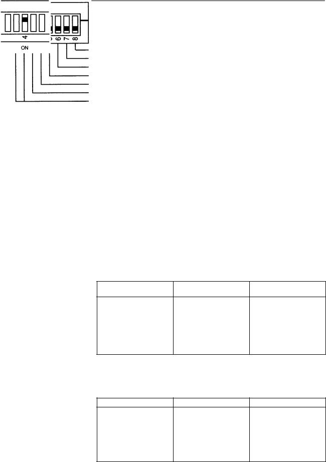
2-3-3 FUNCTION Switch
The FUNCTION switch is used to set the parameters of the E5ZE, such as the baud rate and startup operation.
Operation mode change
FUNCTION Not used. (Always set to OFF.)
Temperature unit (°C or °F)
Startup operation
E5ZD-SDL Setting Display Unit connection
Memory bank designation method
Baud rate (serial communications)
Baud Rate (Serial |
Set the baud rate using pins 1 and 2 to the baud rate of the host device con- |
||||
Communications) |
nected to the EZ5E. |
|
|
||
|
|
|
|
|
|
Baud rate |
|
19,200 bps |
9,600 bps |
4,800 bps |
2,400 bps |
|
|
|
|
|
|
Pin 1 |
|
|
|
|
|
Pin 2 |
|
|
|
|
|
|
|
|
|
|
|
The factory setting is 9,600 bps (pin 1 ON, pin 2 OFF).
Memory Bank Designation Pin 3 is used to set the memory bank designation method.
Method
Memory bank |
Communications |
Contact inputs |
designation |
|
|
Pin 3
The factory setting is for communications (pin 3 OFF).
When contact inputs are used to switch memory banks, the specified memory bank will be used for all control points.
E5ZD-SDL Setting Display Pin 4 is used to specify when an E5ZD-SDL Setting Display Unit is connected.
Unit Connection
E5ZD-SDL connection |
Not connected |
Connected |
Pin 4
The factory setting is for no connection (pin 4 OFF). Set pin 4 to ON when an
E5ZD-SDL Setting Display Unit is to be connected to the E5ZE.
13
|
Setting Selectors and Switch |
|
|
Section 2-3 |
|
|
|
|
|
|
|
Startup Operation |
Pin 5 is used to set the startup operation. |
|
|
||
|
|
|
|
|
|
|
|
Startup operation |
Stop operation control |
Continue status at |
|
|
|
|
|
power OFF |
|
|
|
|
|
|
|
|
|
Pin 5 |
|
|
|
|
|
|
|
|
|
The factory setting is for stop operation control (pin 5 OFF).
If the power is turned OFF during manual operation and pin 5 is set to ON (continuous operation), manual operation will automatically begin when the power is turned ON again. The output value will be 0%.
Temperature Unit |
Pin 6 is used to set the unit for measuring temperature. |
|
||
|
|
|
|
|
|
Temperature unit |
_C |
|
_F |
|
|
|
|
|
|
Pin 6 |
|
|
|
|
|
|
|
|
The factory setting is for degrees Celsius (pin 6 OFF).
When the temperature unit is changed, the temperature data does not automatically change, so make sure to reset the temperature using the following procedure.
1, 2, 3... 1. Initialize the setting data.
2.Recalculate the data according to the following conversion formula and reset the control data within the setting range.
(value in _F) = 1.8 x (value in _C) + 32
3.Store the settings in memory.
Operation Mode Change Pins 3, 4, 5, and 8 are used to change the operation mode.
E5ZE operation mode |
Control mode |
Hardware test mode |
Pins 3, 4, 5, and 8
The factory setting is for Control Mode (pins 3, 4, 5, and 8 all OFF).
Control Mode: |
Use for normal temperature control. |
Hardware Test Mode: Use for testing Peripheral Devices and wiring.
Refer to Appendix E for details on how to use Hardware Test Mode. Outputs can be turned ON and OFF in Hardware Test Mode regardless of the process value.
14

Installation |
Section 2-4 |
2-4 Installation
2-4-1 External and Panel Dimensions
Serial Communications Model |
Unit: mm |
Mounting Hole Dimensions |
|
|
|
|
|
Four, M4 |
E5ZE-8jjjD1jB |
Four, M4 |
|
(DeviceNet Interface) |
||
|
15

Installation |
Section 2-4 |
2-4-2 Mounting
Precautions
Mounting Bracket
Mounting Models
Secure the mounting bracket
Mount the Unit using the methods shown here. The Unit will not operate properly if other methods are used to mount the Unit.
•Use the following mounting screws. Make sure the length of the screws is appropriate for the mounting panel used.
E5ZE-8jjjjjB: 4 x M4 screws
•Use spring and flat washers and tighten to a torque of 0.43 to 0.58 N S m {4.4 to 5.9 kgf S cm}.
•Do not mount the terminal block with the connectors facing upwards. Doing so may cause measurement errors.
Secure the mounting bracket using the screws provided according to the appropriate mounting method. Tighten to a torque of 0.43 to 0.58 N S m {4.4 to 5.9 kgf S cm}.
|
|
Mounting screws |
Mounting screws |
Secure the mounting |
(4 x M4 + spring Panel |
(4 x M4 + spring |
bracket |
and flat washers) |
and flat washers) |
|
|
Panel |
|
|
16

Power Supply and Input Wiring |
Section 2-5 |
2-5 Power Supply and Input Wiring
2-5-1 Terminal Block
The input terminal block has been designed with a removable terminal-screw panel. When connecting the power supply or temperature sensor, the terminalscrew panel can be conveniently removed before wiring.
•To remove the terminal-screw panel, loosen the two screws alternately indicated by A in the above diagram.
•To mount the terminal-screw panel, insert it into the terminal block and secure the two screws (A) alternately.
•If the terminal block has been removed from the E5ZE Thermocouple Input Model, when reconnecting make sure that the E5ZE’s lot number and serial number are the same as those of the terminal block. Accuracy cannot be guaranteed for a Unit that has been connected to a terminal block with a different lot number and serial number.
2-5-2 Wiring
•Always turn OFF the power supply before performing any wiring.
•Be sure to check polarity when connecting the power supply and temperature sensor.
•Wire the power supply cables separately from the temperature sensor cables to prevent noise interference.
•Use either crimp terminals or solder the wire ends when wiring terminals.
•Tighten the terminal screws.
•Wire the power lines close to the terminal block to prevent external force being exerted on the power lines from torsion or weight.
•Do not use the terminals that are marked “Don’t use.”
•Do not bend the crimp terminals after they have been connected and the screws have been tightened.
17
Power Supply and Input Wiring |
Section 2-5 |
• Use the crimp terminals shown in the following diagram.
Crimp Terminals |
Terminal Block Screw Dimensions |
|
|
|
9.5 mm |
|
7.9 mm max. |
|
|
8.1 mm |
8 x M3.5 self-rising screws |
|
7.9 mm max. |
|
End Soldering
Length of exposed wire: 6 to 8 mm
Applicable wire size: AWG 22 to 16
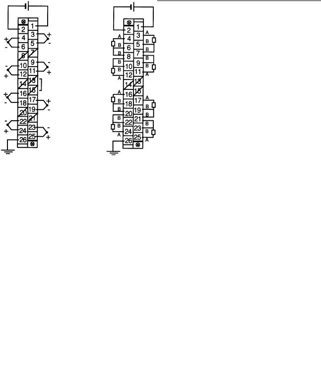
2-5-3 Terminal Arrangement
The following diagram shows the arrangement of terminals on the terminal block.
Thermocouple |
Platinum Resistance Thermometer |
24 VDC |
24 VDC |
ch 0 |
ch 4 |
ch 0 |
ch 4 |
|
|
||
Don’t use |
Don’t use |
|
|
|
|
|
|
ch 1 |
ch 5 |
ch 1 |
ch 5 |
|
|
||
Don’t use |
Don’t use |
Don’t use |
Don’t use |
ch 2 |
|
ch 2 |
|
|
ch 6 |
|
ch 6 |
Don’t use |
Don’t use |
|
|
|
|
|
|
ch 3 |
|
ch 3 |
|
|
ch 7 |
|
ch 7 |
FG |
|
FG |
|
2-5-4 Power Supply
The power supply specifications are as follows: 24 VDC (20.4 to 26.4 VDC) 15 W + 20% max.
Use a power supply with a minimum capacity of 2 A. Be sure to consider the inrush current.
2-5-5 Ground
Connect the ground wire to terminal 26. Ground to 100 Ω max.
18
Loading...