


 LCD Projector
MT1065/MT1060/MT860

User’s Manual

LIMITED WARRANTY
Except as specified below, the warranty that may be provided by the dealer covers all defects in material or workmanship in this product. The following are not covered by the warranty:
1.Any product on which the serial number has been defaced, modified or removed.
2.Damage, deterioration or malfunction resulting from;
a.Accident, misuse, abuse, neglect, fire, water, dust, smoke, lightning or other acts of nature, unauthorized product modification, or failure to follow instructions supplied with the product.
b.Repair or attempted repair by non-authorized persons.
c.Any shipment of product (claim must be presented to the carrier).
d.Removal or installation of the product.
e.Any other causes which do not relate to a product defect.
3.Cartons, carrying cases, batteries, external cabinets, CDROM, or anyaccessories used in connection with the product.
4.Removal or installation charges.
5.Cost of initial technical adjustments (set-up), including adjustment of user controls. These costs are the responsibility of the dealer from whom the product was purchased.
6.Payment of shipping charges.
GARANZIA LIMITATA
A parte la specificazione seguente, la graanzia che potrebbe essere fornita dal rivenditore copre tutti i difetti di materiali o nella lavorazione in questo prodotto. I seguenti non sono coperti dalla garanzia :
1.Ogni prodotto che ha il numero seriale difettoso, modificato o rimosso.
2.Danni, deterioramento o malfunzionamento risultanti da;
a.Incidenti, abuso, cattivo uso, negligenza, fuoco, acqua, polvere, fumo, fulmini o altri atti naturali di tipo naturale, modifiche inautorizzate del prodotto, o errori nel seguire le istruzioni fornite con il prodotto.
b.Riparazioni o tentativi di riparazioni effettuati da persono non autorizzate.
c.Qualsiasi trasporto del prodotto (i reclami devono essere presentati dal corriere).
d.Rimozione o installazione del prodotto.
e.ogni altra causa non relativa ad un deficit del prodotto.
3.Cartoni, scatole di trasporto, batterie, armadietti esterni, CDROM, o qualsiasi altro accessorio annesso al prodotto.
4.Carichi di rimozione o installazione.
5.Costi di aggiustamenti tecnici iniziali (set-up), includendo i comandi di regolazione. Il rivenditore dal quale avete acquistato il prodotto è responsabile di ciò.
6.Pagamento delle spese di consegna.
GARANTIE LIMITEE
Mis à part les point indiqués ci-dessous, la garantie pouvant être couverte par le revendeur comporte l’ensemble des défauts se rapportant au matériel ou aux travaux d’assemblage sur ce produit. Les points suivants ne sont pas couverts par la garantie:
1.Les produits dont les numéro de série a été effacé, modifié ou retiré.
2.Dommages, dégâts ou dysfonctionnement suite à;
a.Un accident, mauvaise utilisation, abus, négligences, incendies, dégats dûs aux eaux, à la poussière, à la fumée, aux éclairs ou autres phénomènes naturels, à une modification non autorisée du produit, ou à la nonconformité aux instructions fournies avec le produit.
b.Réparation ou tentative de réparation par des personnes non autorisées.
c.Toute expédition du produit (les plaintes doivent être adressées à la société de frêt).
d.Démontage ou installation du produit.
e.Toute autre cause ne se rapportant pas à un défaut du produit.
3.Les cartons, boîtes, piles, caissons externes, CDROM, ou tout autre accessoire utilisé avec ce poduit.
4.Prix de démontage ou d’installation.
5.Coût des réglages techniques de base (mise au point), incluant les réglages des commandes utilisateurs. Ces coûts sont placés sous la responsabilité du revendeur auprès duquel le produit a été acheté.
6.Paiement des frais de transport.
GARANTÍA LIMITADA
A excepción de lo que se especifica abajo, la garantía que puede ser suministrada por el distribuidor cubre todos los defectos en material o elaboración en este producto. Lo siguiente no es cubierto por la garantía:
1.Cualquier producto en el cual el número serial haya sido desfigurado, modificado o removido.
2.Daños, deterioro o malfuncionamiento resultado de;
a.Accidente, mal manejo, abuso, negligencia, fuego, agua, polvo, humo, relámpagos u otros fenómenos naturales, modificaciones del producto sin autorización, fallas en el seguimiento de las instrucciones suministradas con el producto.
b.Reparación o intentos de reparación por personas no autorizadas.
c.Cualquier envío del producto (el reclamo debe presentarse al transportador).
d.Remoción o instalación del producto.
e.Cualquier otra causa que no este relacionada con un defecto del producto.
3.Cartones, estuches de transporte, pilas, gabinetes externos, CDROM, o cualquier accesorio utilizado en conexión con el producto.
4.Costos por instalación o remoción.
5.Costo de los ajustes técnicos iniciales (configuración), incluyendo el ajuste de los controles de usuario. Estos costos son responsabilidad del distribuidor donde se adquirió el producto.
6.Pago de los costos de envío.
BESCHRÄNKTE GARANTIE
Außer in den unten beschriebenen Fällen deckt die vom Händler unter Umständen gewährte Garantie alle Materialoder Herstellungsfehler dieses Produktes ab. In den folgenden Fällen wird keine Garantie gewährt:
1.Wenn die Seriennummer des Produktes unleserlich gemacht, geändert oder entfernt worden ist.
2.Bei einer Beschädigung, Beeinträchtigung oder Funktionsstörung, die aus folgenden Fällen resultiert:
a.Unfall, falscher Gebrauch, Missbrauch, Fahrlässigkeit, Feuer, Wasser, Staub, Rauch, Blitzeinschlag oder andere Naturereignisse, nicht autorisierte Veränderungen des Produktes oder die Missachtung der dem Produkt beigefügten Anleitung.
b.Reparatur oder der Versuch einer Reparatur durch nicht autorisierte Personen.
c.Jeglicher Transport des Produktes (die Haftung liegt in diesem Fall bei der den Transport durchführenden Person).
d.Entfernung oder Installation des Produktes.
e.Jegliche andere Ursachen, die nicht mit einem Defekt dieses Produktes zusammenhängen.
3.Verwendung von Kartons, Transportkisten, Batterien, Außengehäusen, CD-ROMs oder anderem Zubehör zusammen mit diesem Produkt.
4.Entfernungsoder Installationsforderungen und –kosten.
5.Kosten der technischen Anfangseinstellungen (Setup), einschließlich der Einstellungen der Benutzersteuerungen. Diese Kosten sind vom Händler zu tragen, von dem das Produkt erworben wurde.
6.Bezahlung von Transportkosten.
BEGRÄNSAD GARANTI
Garantin som ges av återförsäljaren täcker alla brister i material och utförande med undantag av vad som anges nedan. Följande täcks inte av garantin:
1.Produkter vars serienummer har blivit oläsligt, modifierats eller tagits bort.
2.Skador, försämring eller felfunktion som beror på:
a.Olyckor, fel bruk, missbruk, vanskötsel, brand, vatten, rök, stoft, åska eller annan orsak som beror på naturen, icke auktoriserad modifikation av produkten samt underlåtenhet att följa anvisningarna som lämnas med produkten.
b.Reparationer eller försök på reparation av icke auktoriserade personer.
c.Transportskador (dessa bör riktas till transportföretaget).
d.Avmontering eller installation av produkten.
e.Övriga orsaker som inte har något samband med produktens fel.
3.Förpackningslådor, bärväskor, batterier, externa höljen, CD-ROM- skivor samt andra tillbehör som används tillsammans med produkten.
4.Avmonteringsoch installationskostnader.
5.Kostnader för tekniska justeringar (inställning), inklusive justering av användarreglagen. Dessa kostnader är återförsäljarens ansvar där produkten köpts.
6.Betalning för transportkostnader.
LIMITED WARRANTY (USA and Canada only)
NEC SOLUTIONS’ PROJECTOR PRODUCTS
NEC Solutions (America), Inc. (hereafter NEC Solutions) warrants this product to be free from defects in material and workmanship under the following terms.
HOW LONG IS THE WARRANTY
NEC Solutions’ MT1065, MT1060, MT860 and MT1060R projectors are covered by a two (2) year limited parts and labor warranty from the date of the first customer purchase. The lamp when used under normal operating conditions is warranted for 1000 hours or six months, whichever comes first.
WHO IS PROTECTED
This warranty may be enforced only by the first purchaser, and is not transferable.
WHAT IS COVERED AND WHAT IS NOT COVERED
Except as specified below, this warranty covers all defects in material or workmanship in this product.
NEC SOLUTIONS’ LIABILITY FOR ANY DEFECTIVE PRODUCT IS LIMITED TO THE REPAIR OR REPLACEMENT OF THE PRODUCT AT NEC SOLUTIONS’ OPTION. REPLACEMENT PRODUCTS MAY BE NEW OR ‘LIKE NEW’. The following are not covered by the limited warranty and NEC Solutions shall not be liable for:
1.Any product which is not distributed in the U.S.A. or Canada by NEC Solutions or which is not purchased, installed, and operated in the U.S.A or Canada.
2.Any product on which the serial number has been defaced, modified or removed.
3.Normal decrease in lamp light output over time.
4.Damage, deterioration or malfunction resulting from:
a.Accident, misuse, abuse, neglect, improper ventilation, fire, dust, smoke, water, lightning or other acts of nature, unauthorized product modification, or failure to follow instructions supplied with the product.
b.Repair or attempted repair by anyone other than a NEC Solutions authorized service center.
c.Any shipment of the product (claims must be presented to the carrier).
d.Removal or installation of the product.
e.Any other cause which does not relate to a product defect.
f.Use of the product beyond normal operating conditions. Normal operating conditions are defined as product use not in excess of 8 hours per day and 260 days per year.
5.Cartons, carrying cases, shipping cases, batteries, external cabinets, magnetic tapes, or any accessories used in connection with the product.
6.Service required as a result of third party components.
WHAT NEC SOLUTIONS WILL PAY FOR
NEC Solutions will pay labor and material expenses for covered items, but NEC Solutions will not pay for the following:
1.Removal or installation charges.
2.Costs of technical adjustments, set-up, maintenance, or adjustment of user controls.
3.Payment of shipping and related charges incurred in returning the product for warranty repair.
HOW YOU CAN GET WARRANTY SERVICE
1.To obtain service on your product, consult the dealer from whom you purchased the product.
2.Whenever warranty service is required, the original dated invoice (or a copy) must be presented as proof of warranty coverage. In order to obtain warranty service, you may be required to describe and demonstrate the problem to your dealer or to NEC Solutions.
3.All products returned to NEC Solutions for service MUST have prior approval. To receive approval or for the name of the nearest NEC Solutions authorized service center, call NEC Solutions at 800-836-0655.
4.It shall be your obligation and expense to ship the product, freight prepaid, or to deliver it to a NEC Solutions authorized service center, in either the original package or a similar package affording an equal degree of protection.
5.In the event a product is returned to NEC Solutions for warranty service, and it is determined that there is no product defect or that the product condition is not covered by this limited warranty, a diagnostic service fee may be charged to the customer.
LIMITATION OF IMPLIED WARRANTIES
EXCEPT AS EXPRESSLY SET FORTH IN THIS LIMITED WARRANTY, NEC SOLUTIONS MAKES NO OTHER WARRANTIES, EXPRESS OR IMPLIED, INCLUDING BUT NOT LIMITED TO ANY IMPLIED WARRANTIES OR CONDITIONS OF MERCHANTABILITY AND FITNESS FOR A PARTICULAR PURPOSE. ANY IMPLIED WARRANTIES THAT MAY BE IMPOSED BY LAW ARE LIMITED TO THE TERMS AND DURATION OF THIS LIMITED WARRANTY.
EXCLUSION OF DAMAGES
NEC SOLUTIONS’ LIABILITY FOR ANY DEFECTIVE PRODUCT IS LIMITED TO THE REPAIR OR REPLACEMENT OF THE PRODUCT AT NEC SOLUTIONS’ OPTION. NEC SOLUTIONS SHALL NOT BE LIABLE FOR:
1.DAMAGE TO OTHER PROPERTY CAUSED BY ANY DEFECTS IN THIS PRODUCT, DAMAGES BASED UPON INCONVENIENCE, LOSS OF USE OF THE PRODUCT, LOSS OF TIME, COMMERCIAL LOSS; OR
2.ANY OTHER DAMAGES, WHETHER INCIDENTAL, CONSEQUENTIAL OR OTHERWISE.
HOW STATE LAW RELATES TO THE WARRANTY
SOME STATES DO NOT ALLOW LIMITATIONS ON HOW LONG AN IMPLIED WARRANTY LASTS AND/OR DO NOT ALLOW THE EXCLUSION OR LIMITATION OF INCIDENTAL OR CONSEQUENTIAL DAMAGES, SO THE ABOVE LIMITATIONS AND EXCLUSIONS MAY NOT APPLY TO YOU. THIS LIMITED WARRANTY GIVES YOU SPECIFIC LEGAL RIGHTS, AND YOU MAY HAVE OTHER RIGHTS WHICH VARY FROM STATE TO STATE.
FOR MORE INFORMATION, CONTACT:
NEC SOLUTIONS (AMERICA), INC.
1250 N. Arlington Heights Road, Suite 500 Itasca, Illinois 60143-1248
TELEPHONE 800-836-0655 www.necvisualsystems.com
Customers are cautioned that product performance is affected by system configuration, software, the application, customer data, and operator control, among other factors. While NEC Solutions’ products are considered to be compatible with many systems, the specific functional implementation by the customers of the product may vary. Therefore, the suitability of a product for a specific purpose or application must be determined by the customer and is not warranted by NEC Solutions.
Printed in Japan
7N8P1942

DECLARATION OF CONFORMITY
This device complies with Part 15 of FCC Rules. Operation is subject to the following two conditions.
(1) This device may not cause harmful interference, and (2) this device must accept any interference received, including interference that may cause undesired operation.
U.S. Responsible Party: |
NEC Solutions (America), Inc. |
Address: |
1250 N. Arlington Heights Road |
|
Itasca, Illinois 60143 |
Tel. No.: |
(630) 467-5000 |
Type of Product: |
LCD Projector |
Equipment Classification: |
Class B Peripheral |
Models: |
MT1065, MT1060, MT860 and MT1060R |
We hereby declare that the equipment specified above
conforms to the technical standards as specified in the FCC Rules.

Portable Projector

 MT1065/MT1060/MT860
English
User’s  Manual

Deutsch
Français
Italiano
Español
Svenska

Important Information
Safety Cautions
Precautions
Please read this manual carefully before using your NEC MT1065/ MT1060/MT860 Projector and keep the manual handy for future reference. Your serial number is located on the right side of your projector. Record it here:
CAUTION
To turn off main power, be sure to remove the plug from power outlet.
The power outlet socket should be installed as near to the equipment as possible, and should be easily accessible.
CAUTION
TO PREVENT SHOCK, DO NOT OPEN THE CABINET. NO USER-SERVICEABLE PARTS INSIDE.
REFER SERVICING TO QUALIFIED NEC SERVICE PERSONNEL.
This symbol warns the user that uninsulated voltage within the unit may be sufficient to cause electrical shock. Therefore, it is dangerous to make any kind of contact with any part inside of the unit.
This symbol alerts the user that important information concerning the operation and maintenance of this unit has been provided.
The information should be read carefully to avoid problems.
WARNING
TO PREVENT FIRE OR SHOCK, DO NOT EXPOSE THIS UNIT TO RAIN OR MOISTURE.
DO NOT USE THIS UNIT’S GROUNDED PLUG WITH AN EXTENSION CORD OR IN AN OUTLET UNLESS ALL THREE PRONGS CAN BE FULLY INSERTED.
DO NOT OPENTHE CABINET.THERE ARE HIGH-VOLTAGE COMPONENTS INSIDE. ALL SERVICING MUST BE DONE BY QUALIFIED NEC SERVICE PERSONNEL.
DOC Compliance Notice
This Class B digital apparatus meets all requirements of the Canadian Interference-Causing Equipment Regulations.
Acoustic Noise Information Ordinance-3. GSGV:
The sound pressure level is less than 70 dB (A) according to ISO 3744 or ISO 7779.
This label is on the side of the remote control.
CAUTION
Do not look into the laser pointer while it is on and do not point the laser beam at a person. Serious injury could result.
RF Interference
WARNING
The Federal Communications Commission does not allow any modifications or changes to the unit EXCEPT those specified by NEC Soluctions (America), Inc. in this manual. Failure to comply with this government regulation could void your right to operate this equipment. This equipment has been tested and found to comply with the limits for a Class B digital device, pursuant to Part 15 of the FCC Rules.These limits are designed to provide reasonable protection against harmful interference in a residential installation. This equipment generates, uses, and can radiate radio frequency energy and, if not installed and used in accordance with the instructions, may cause harmful interference to radio communications. However, there is no guarantee that interference will not occur in a particular installation. If this equipment does cause harmful interference to radio or television reception, which can be determined by turning the equipment off and on, the user is encouraged to try to correct the interference by one or more of the following measures:
•Reorient or relocate the receiving antenna.
•Increase the separation between the equipment and receiver.
•Connect the equipment into an outlet on a circuit different from that to which the receiver is connected.
•Consult the dealer or an experienced radio / TV technician for help.
In UK, a BS approved power cable with moulded plug has a Black (five Amps) fuse installed for use with this equipment. If a power cable is not supplied with this equipment please contact your supplier.
Important Safeguards
These safety instructions are to ensure the long life of your projector and to prevent fire and shock. Please read them carefully and heed all warnings.
Installation
1.For best results, use your projector in a darkened room.
2.Place the projector on a flat, level surface in a dry area away from dust and moisture.
To avoid premature lamp failure, do not tilt the front of the projector up or down by more than 15° from level.
3.Do not place your projector in direct sunlight, near heaters or heat radiating appliances.
4.Exposure to direct sunlight, smoke or steam can harm internal components.
5.Handle your projector carefully. Dropping or jarring can damage internal components.
6.Do not place heavy objects on top of the projector.
7.If you wish to have the projector installed on the ceiling:
a.Do not attempt to install the projector yourself.
b.The projector must be installed by qualified technicians in order to ensure proper operation and reduce the risk of bodily injury.
c.In addition, the ceiling must be strong enough to support the projector and the installation must be in accordance with any local building codes.
d.Please consult your dealer for more information.
E-2

Fire and Shock Precautions
1.Ensure that there is sufficient ventilation and that vents are unobstructed to prevent the build-up of heat inside your projector. Allow at least 3 inches (10 cm) of space between your projector and a wall.
2.Prevent foreign objects such as paper clips and bits of paper from falling into your projector.
Do not attempt to retrieve any objects that might fall into your projector. Do not insert any metal objects such as a wire or screwdriver into your projector. If something should fall into your projector, disconnect it immediately and have the object removed by a qualified NEC service personnel.
3.Do not place any liquids on top of your projector.
4.Do not look into the lens while the projector is on. Serious damage to your eyes could result.
5.Keep any items such as magnifying glass out of the light path of the projector. The light being projected from the lens is extensive, therefore any kind of abnormal objects that can redirect light coming out of the lens, can cause unpredictable outcome such as fire or injury to the eyes.
6.Do not cover the lens with the supplied lens cap or equivalent while the projector is on. Doing so can lead to melting of the cap and possibly burning your hands due to the heat emitted from the light output.
7.The projector is designed to operate on a power supply of 100-120 or 200-240 V 50/60 Hz AC. Ensure that your power supply fits this requirement before attempting to use your projector.
8.Handle the power cable carefully and avoid excessive bending. A damaged cord can cause electric shock or fire.
9.If the projector is not to be used for an extended period of time, disconnect the plug from the power outlet.
CAUTION
1.Do not try to touch the ventilation outlet on the front as it can become heated while the projector is turned on.
2.Do no use the tilt-foot for purposes other than originally intended. Misuses such as gripping the tilt-foot or hanging on the wall can cause damage to the projector.
3.Enable High-Speed Fan mode if you continue to use the projector
for consecutive days. (From the Advanced menu, select [Projector Options] → [Setup] → [Page 4] → [High Speed Fan Mode].)
4.Do not unplug the power cable from the wall outlet under any one of the following circumstances.
Doing so can cause damage to the projector:
*While the Hour Glass icon appears.
*While the message "Please wait a moment." appears.This message will be displayed after the projector is turned off.
*While the cooling fans are running. (The cooling fans continue to work for 90 seconds after the projector is turned off).
5.Do not eject the PC card or LAN card while its data is being accessed. Doing so can damage your PC card or LAN card data.
Lamp Replacement
•To replace the lamp, follow all instructions provided on page E-53.
•Be sure to replace the lamp when the message "The lamp has reached the end of its usable life. Please replace the lamp." appears. If you continue to use the lamp after the lamp has reached the end of its usable life, the lamp bulb may shatter, and pieces of glass may be scattered in the lamp case. Do not touch them as the pieces of glass may cause injury.
If this happens, contact your NEC dealer for lamp replacement.
•Allow a minimum of 90 seconds to elapse after turning off the projector. Then turn off the main power switch, disconnect the power cable and allow 60 minutes to cool the projector before replacing the lamp.
What's in the Box?
Make sure your box contains everything listed. If any pieces are missing, contact your dealer.
Please save the original box and packing materials if you ever need to ship your MT1065/MT1060/MT860 Projector.
Lens cap
Remote Control Cable
Projector
USB mouse
|
|
|
|
SELECT |
|
|
|
|
PJ |
|
|
A |
|
|
|
|
|
SPECT |
|
VOL |
HELP |
FREEZE |
3DR |
|
UME |
|
INTER |
||
|
|
EFO |
||
|
MA |
GNIFY |
PIC- |
RM |
|
|
MUTE |
||
ZOOM |
|
|
SLIDE |
|
F |
|
|
|
|
OCUS |
|
|
|
|
FOLDER |
|
|
|
|
SLIDE |
|
|
|
|
LIST |
|
|
|
|
Remote control Batteries String and rivet
Power cable |
USB cable |
RGB signal cable |
|
|
|
|
|
|
|
|
Quick |
|
Connect |
||
User's |
Guide |
|
|
|
|
|
|
Manual |
|
|
|
|
Software NEC |
||
|
Installation |
|
Utility |
|
|
Guide |
|
For North America only
Registration card Limited warranty
For Europe only
Guarantee policy
CD-ROM
Projector User Supportware
E-3
TABLE OF CONTENTS
Important Information ..................................................... |
E-2 |
Safety Cautions ............................................................................................................... |
E-2 |
What's in the Box? .......................................................................................................... |
E-3 |
INTRODUCTION .............................................................. |
E-5 |
Introduction to the Projector ........................................................................................... |
E-5 |
Part Names of the Projector ............................................................................................ |
E-6 |
Attaching the lens cap ................................................................................................. |
E-6 |
Carrying the Projector ................................................................................................. |
E-6 |
Top Features ................................................................................................................ |
E-7 |
Terminal Panel Features ............................................................................................... |
E-8 |
Part Names of the Remote Control .............................................................................. |
E-9 |
Battery Installation ................................................................................................. |
E-11 |
Remote Control Precautions .................................................................................. |
E-11 |
Operating Range for Wireless Remote Control ...................................................... |
E-11 |
Using the Remote Control in Wired Operation ....................................................... |
E-11 |
INSTALLATION AND CONNECTIONS ....................................... |
E-12 |
Setting Up the Screen and the Projector ....................................................................... |
E-12 |
Selecting a Location .................................................................................................. |
E-12 |
Throw Distance and Screen Size ............................................................................... |
E-13 |
Making Connections ...................................................................................................... |
E-14 |
When Viewing a DVI Digital Signal ............................................................................ |
E-14 |
Connecting Your PC or Macintosh Computer ............................................................ |
E-14 |
To connect SCART output (RGB) ............................................................................... |
E-15 |
Connecting an External Monitor ................................................................................ |
E-15 |
Connecting Your DVD Player ..................................................................................... |
E-16 |
Connecting Your VCR or Laser Disc Player ............................................................... |
E-17 |
Connecting the Supplied Power Cable ....................................................................... |
E-17 |
PROJECTING AN IMAGE (BASIC OPERATION) ........................... |
E-18 |
Turning on the Projector ................................................................................................ |
E-18 |
Selecting a Source ......................................................................................................... |
E-19 |
Adjusting the Picture Size and Position ......................................................................... |
E-19 |
Correcting the Horizontal and Vertical Keystone Distortion (3D Reform) ...................... |
E-20 |
Optimizing RGB Picture Automatically .......................................................................... |
E-22 |
Turning Up or Down Volume ......................................................................................... |
E-22 |
Using the Laser Pointer ................................................................................................. |
E-22 |
Setting the function switch ............................................................................................ |
E-23 |
Turning off the Projector ............................................................................................... |
E-23 |
CONVENIENT FEATURES ................................................... |
E-24 |
Using the Remote Mouse Function ............................................................................... |
E-24 |
Connecting to your computer for the remote mouse function ................................... |
E-24 |
When using the USB Port .......................................................................................... |
E-24 |
Switching operation mode between computer and projector ..................................... |
E-24 |
Turning Off the Image and Sound .................................................................................. |
E-25 |
Freezing a Picture .......................................................................................................... |
E-25 |
Using the Pointer .......................................................................................................... |
E-25 |
Enlarging and Moving a Picture ..................................................................................... |
E-25 |
Getting the On-line Help ................................................................................................ |
E-25 |
Using the USB Mouse ................................................................................................... |
E-26 |
Using the USB HUB Function ........................................................................................ |
E-26 |
Changing Background Logo .......................................................................................... |
E-27 |
Making Freehand Drawings on a Projected Image (ChalkBoard) ................................... |
E-27 |
USING THE VIEWER ........................................................ |
E-28 |
Making the Most out of the Viewer Function ................................................................. |
E-28 |
Operating the Viewer Function from the Projector (playback) ....................................... |
E-29 |
Projecting slides (Viewer) .......................................................................................... |
E-29 |
Auto Play Mode ......................................................................................................... |
E-30 |
Switching to Slides Directly from Other Input Modes ................................................ |
E-30 |
Viewing Digital Images .............................................................................................. |
E-30 |
Storing Images Displayed on the Projector on the PC card (Capture) ....................... |
E-30 |
Deleting Captured Images ......................................................................................... |
E-31 |
Using the PC Card Files Fucntion (PC Card Files) ...................................................... |
E-31 |
Selecting Video Filter Level .................................................................................... |
E-39 |
Selecting Noise Reduction Level ............................................................................ |
E-39 |
Signal Type ............................................................................................................ |
E-39 |
Picture Management .................................................................................................. |
E-39 |
User Adjust (when using User 1 to 4) .................................................................... |
E-39 |
Selecting Gamma Correction Mode ................................................................ |
E-40 |
Selecting Color Correction ............................................................................. |
E-40 |
Adjusting Color Temperature and White Balance ............................................ |
E-40 |
Selecting Base Setting .................................................................................... |
E-40 |
Projector Options ...................................................................................................... |
E-40 |
Using 3D Reform ................................................................................................... |
E-40 |
Cornerstone ................................................................................................... |
E-40 |
Keystone ........................................................................................................ |
E-40 |
Using Adapting Color Correction ........................................................................... |
E-41 |
Menu [Page1] ........................................................................................................ |
E-43 |
Selecting Menu Language/Selecting Menu Mode/Customizing the Menu/Select- |
|
ing Projecting Pointer Icon/Selecting Menu Display Time |
|
Menu [Page 2] ....................................................................................................... |
E-43 |
Turning On / Off Source Display / Turning On / Off Message / Selecting Menu |
|
Color |
|
Setup [Page 1] ....................................................................................................... |
E-44 |
Selecting Projector Orientation/Selecting a Color or Logo for Background/Setting |
|
RGB 1 or 2 for RGB OUT/Setting Closed Caption |
|
Setup [Page 2] ....................................................................................................... |
E-44 |
Setting Viewer Options/Selecting Capture Options/Setting Mouse Button and Sen- |
|
sitivity/Selecting Operation Mode |
|
Setup [Page 3] ....................................................................................................... |
E-45 |
Selecting Signal Format [Signal Select] |
|
Setup [Page 4] ....................................................................................................... |
E-45 |
Enabling Auto Adjust/Enabling Auto Start/Enabling Power Management/Enabling Power Off Confirmation/Enabling Horizontal and Vertical Keystone Correction Save /Enabling High Speed Fan Mode/Selecting Built-in Speakers/Enabling Idle Mode
Setup [Page 5] ....................................................................................................... |
E-46 |
Remote Sensor/S-Video Mode Select |
|
Setup [Page 6] ....................................................................................................... |
E-46 |
Selecting Communication Speed/Selecting Default Source/Disabling the Cabinet |
|
Buttons |
|
Selecting Lamp Mode and Lamp Type ................................................................... |
E-46 |
Selecting Aspect Ratio and Position for Screen ..................................................... |
E-47 |
Selecting Auto Functions ....................................................................................... |
E-47 |
Setting LAN Mode ..................................................................................................... |
E-48 |
IP Address ............................................................................................................. |
E-48 |
Network Type ......................................................................................................... |
E-48 |
WEP ....................................................................................................................... |
E-49 |
Mail ........................................................................................................................ |
E-49 |
Status .................................................................................................................... |
E-50 |
Setting a Password .................................................................................................... |
E-50 |
Security ..................................................................................................................... |
E-51 |
Tools .......................................................................................................................... |
E-52 |
Using Sleep Timer/Using Capture/Using PC Card Files/Using ChalkBoard |
|
Help ........................................................................................................................... |
E-52 |
Contents ................................................................................................................ |
E-52 |
Information ............................................................................................................ |
E-52 |
Returning to Factory Default ...................................................................................... |
E-52 |
MAINTENANCE ............................................................. |
E-53 |
Replacing the Lamp ...................................................................................................... |
E-53 |
Cleaning ........................................................................................................................ |
E-54 |
Cleaning or Replacing the Filter ................................................................................. |
E-54 |
Cleaning the Cabinet and the Lens ............................................................................. |
E-54 |
TROUBLESHOOTING ........................................................ |
E-55 |
Power Indicator ............................................................................................................. |
E-55 |
Status Indicator ............................................................................................................. |
E-55 |
Lamp Indicator .............................................................................................................. |
E-55 |
Common Problems & Solutions .................................................................................... |
E-56 |
When using the Viewer function .................................................................................... |
E-56 |
USING ON-SCREEN MENU ................................................. |
E-32 |
SPECIFICATIONS ........................................................... |
E-57 |
Basic Menu Operation ................................................................................................... |
E-32 |
APPENDIX |
E-58 |
Using the Menus ....................................................................................................... |
E-32 |
||
Customizing the Menu ............................................................................................... |
E-32 |
Cabinet Dimensions ...................................................................................................... |
E-58 |
Menu tree ...................................................................................................................... |
E-33 |
Pin Assignments of D-Sub RGB Input Connector .......................................................... |
E-58 |
Menu Elements ............................................................................................................. |
E-36 |
Compatible Input Signal List ......................................................................................... |
E-59 |
Entering Alphanumeric Characters by Using the Menu .............................................. |
E-37 |
PC Control Codes and Cable Connection ....................................................................... |
E-60 |
Menu Descriptions & Functions .................................................................................... |
E-37 |
PC Control Connector (D-SUB 9P) ................................................................................ |
E-60 |
Source Select ............................................................................................................ |
E-37 |
Using Software Keyboard .............................................................................................. |
E-60 |
RGB/Video/S-Video/DVI (DIGITAL)/Viewer/LAN/Entry List |
|
Operation Using an HTTP Browser ................................................................................ |
E-61 |
Picture ....................................................................................................................... |
E-38 |
TravelCare Guide ........................................................................................................... |
E-62 |
Sound ........................................................................................................................ |
E-38 |
|
|
Image Options ........................................................................................................... |
E-38 |
|
|
Selecting Aspect Ratio ........................................................................................... |
E-38 |
|
|
Masking Unwanted Area (Blanking) ....................................................................... |
E-39 |
|
|
Adjusting Position and Clock ................................................................................. |
E-39 |
|
|
Horizontal/Vertical Position .................................................................................... |
E-39 |
|
|
Selecting Resolution .............................................................................................. |
E-39 |
|
|
Selecting Overscan Percentage .............................................................................. |
E-39 |
|
|
E-4

INTRODUCTION
Introduction to the Projector
This section introduces you to your new MT1065/MT1060/MT860 Projector and describes the features and controls.
Congratulations on Your Purchase of The MT1065/ MT1060/MT860 Projector
The MT1065/MT1060/MT860 is one of the very best projectors available today. The MT1065/MT1060/MT860 enables you to project precise images up to 500 inches across (measured diagonally) from your PC or Macintosh computer (desktop or notebook), VCR, DVD player, document camera, a laser disc player or Viewer.
You can use the projector on a tabletop or cart, you can use the projector to project images from behind the screen, and the projector can be permanently mounted on a ceiling*1. The remote control can be used wirelessly.
*1 Do not attempt to mount the projector on a ceiling yourself.
The projector must be installed by qualified technicians in order to ensure proper operation and reduce the risk of bodily injury.
In addition, the ceiling must be strong enough to support the projector and the installation must be in accordance with any local building codes. Please consult your dealer for more information.
Features you'll enjoy:
•3D Reform enhanced keystone correction that allows not only horizontal and vertical access but diagonal adjustments.
•Wireless*2 or wired networking access provides easy and effective presentation delivery.
*2 A wireless LAN card is required. The NEC optional wireless LAN card is available. (SWL-2100N-N )
•Safety protect by Password and Security functions
Password and Security features prevent the projector from being used by unauthorized individuals.
Password prevents unauthorized individuals from changing projector settings or adjustments Security offers complete protection by using your PC card as a protect key so that the projector will not project a signal without insertion of the registered PC card and unauthorized use can be discouraged.
•Picture Management enables users to adjust individual color settings to their preferences.
•Eco-mode extends lamp life and reduces total cost of ownership. Standard lamp and optional longer life lamp
•Power zoom and power focus standard lens provide easy adjustment.
•Automatic lens focus provides extreme ease of use
•Automatic Wall Color Correction allows for quick adaptive color correction on textured or painted walls and in applications where the display is other than screen material. With the built-in image sensor, the projector adjusts the colors for screen sizes between 40" and 150" diagonally.
•Variable audio out control via projector
•The built-in Viewer allows you to start your presentation even when a PC is not available at the site.
•A high-bright 275 watt DC lamp (220W Eco mode).
•The Standby mode reduces standby power consumption significantly.
•The supplied wireless remote control that operates the projector from any angle.
•The image can be projected between 25 and 500 inches (measured diagonally).
•The "Capture" enables you to capture the current projected image.
•An image can be projected from in front or behind a screen, and the projector can even be installed on the ceiling.
•NEC’s exclusive Advanced AccuBlend intelligent pixel blending technology - an extremely accurate image compression technology - offers a crisp image with UXGA (1600 1200) resolution*3.
•Supports most IBM VGA, SVGA, XGA, SXGA/UXGA(with Advanced AccuBlend)*3, Macintosh, component signal (YCbCr/ YPbPr) or any other RGB signals within a horizontal frequency range of 24 to 100 kHz and a vertical frequency range of 48 to 120 Hz. This includes NTSC, PAL, PAL-N, PAL-M, PAL60, SECAM and NTSC4.43 standard video signals.
*3 A UXGA (1600 1200) and SXGA (1280 1024) image are displayed with NEC’s Advanced AccuBlend on MT1065 and MT1060.
A UXGA (1600 1200), SXGA (1280 1024) and XGA (1024 768) image are displayed with NEC’s Advanced AccuBlend on MT860.
NOTE: Composite video standards are as follows: NTSC: U.S. TV standard for video in U.S. and Canada. PAL: TV standard used in Western Europe.
PAL-N: TV standard used in Argentine, Paraguay and Uruguay. PAL-M: TV standard used in Brazil.
PAL60: TV standard used for NTSC playback on PAL TVs. SECAM: TV standard used in France and Eastern Europe. NTSC4.43: TV standard used in Middle East countries.
•The supplied remote control can be used without a cable, and you can even use the remote control to operate your PC's mouse wirelessly from across the room with the built-in remote mouse function.
•You can control the projector with a PC using the PC Control port.
•USB port allows USB mouse operation*4.
*4 The USB ports meet the USB1.1 specification.
•The contemporary cabinet design is light, compact, easy to carry, and complements any office, boardroom or auditorium.
•Eight pointers are available for your presentation.
About this user's manual
The fastest way to get started is to take your time and do everything right the first time. Take a few minutes now to review the user's manual. This may save you time later on. At the beginning of each section of the manual you'll find an overview. If the section doesn't apply, you can skip it.
E-5
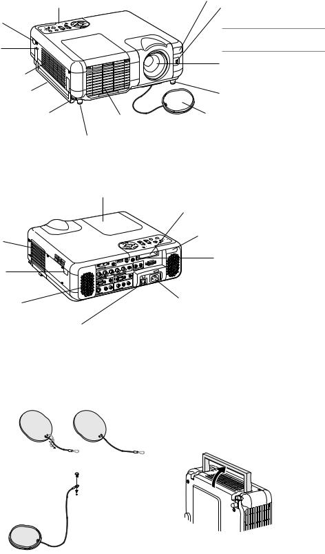
Part Names of the Projector
Controls (See page E-7)
Remote Sensor (See page E-11)
Built-in Security Slot (  )*
)*
Remote Sensor (See page E-11)
Image Sensor
For Auto Focus and Auto Wall Color Correction. (See page E-47)
NOTE: The Auto Focus and the Auto Wall Color Correction are not available on MT860.
Lens
Ventilation (inlet)
Carrying Handle
Adjustable Tilt Foot Lever (See page E-19)
 Adjustable Tilt Foot Lever
(See page E-19)
Adjustable Tilt Foot (See page E-19)
Lens Cap
Ventilation (outlet)
Heated air is exhausted from here
Adjustable Tilt Foot (See page E-19)
*This security slot supports the MicroSaver® Security System. MicroSaver® is a registered trademark of Kensington Microware Inc. The logo is trademarked and owned by Kensington Microware Inc.
Filter Cover (inlet)
Remote Sensor (See page E-11)
Stereo Speaker (5W)
Lamp Cover (See page E-53)
1 2
|
|
|
|
|
REMOTE |
|
|
|
|
|
PC CONTROL |
|
|
|
USB(MOUSE/HUB |
) |
R |
|
|
|
|
L/MONO |
|
|
|
AUDIO |
|
|
AUDIO |
|
|
V |
|
||
|
|
|
H |
|
AUDIO OUT |
DVI IN |
B/Cb |
|
|
||
|
|
G/Y |
|
|
AC IN |
AUDIO |
|
|
|
||
|
|
|
RGB OUT |
|
|
RGB2 |
IN |
|
|
|
AUDIO |
|
|
|
|
||
RGB1 IN |
|
|
|
R |
|
|
|
AUDIO |
L/MONO |
|
|
|
|
R |
|
|
|
|
|
L/MONO |
|
|
AUDIO |
|
|
AUDIO |
VIDEO IN |
|
|
|
|
|
|
|
|
S-VIDEO IN |
|
|
|
|
|
Main Power Switch
When you plug the supplied power cable into an active wall outlet and turn on the Main Power switch, the POWER indicator turns orange and the projector is in standby mode. (See page E-18)
PC Card Slot 1
PC Card Slot 2
Remote Sensor (See page E-11)
PC Card Eject Button
AC Input
Connect the supplied power cable's threepin plug here, and plug the other end into an active wall outlet. (See page E-17)
Attaching the lens cap
To attach the lens cap to the bottom with the supplied string and rivet:
1.Thread the string through the hole on the lens cap and then tie a knot in the string.
2.Use the rivet to attach the string to the bottom of the projector.
Carrying the Projector
Always carry your projector by the handle.
Ensure that the power cable and any other cables connecting to video sources are disconnected before moving the projector.
When moving the projector or when it is not in use, cover the lens with the lens cap.
E-6
Top Features
11 |
10 |
9 |
8 |
5 |
6 |
4
3
2
12 |
13 |
14 |
7 |
1 |
1. POWER Button (ON / STAND BY)(  )
)
Use this button to turn the power on and off when the main power is supplied and the projector is in standby mode.
NOTE: To turn on or off the projector, press and hold this button for a minimum of two seconds.
2. POWER Indicator
When this indicator is green, the projector is on; when this indicator is orange, it is in standby or idle mode. See the Power Indicator section on page E-55 for more details.
3. STATUS Indicator
If this light blinks red rapidly, it indicates that an error has occurred, the lamp cover is not attached properly or the projector has overheated. If this light remains orange, it indicates that you have pressed a cabinet key while the Control Panel Key Lock is enabled. See the Status Indicator section on page E-55 for more details.
4.LAMP Indicator
If this light blinks red rapidly, it's warning you that the lamp has reached the end of its usable life. After this light appears, replace the lamp as soon as possible (See page E-53). If this is lit green continually, it indicates that the lamp mode is set to Eco. See the Lamp Indicator section on page E-55 for more details.
5.SOURCE Button
Use this button to select a video source such as a PC, VCR, DVD player, Viewer (PC card), or LAN.
Press and release this button quickly to display the Source List.
Each time this button is pressed for a minimum of ONE second, the input source will change as follows:
RGB1 → RGB2 → Video → S-Video → DVI (DIGITAL)* → Viewer → RGB1 → ...
If no input signal is present, the input will be skipped.
6.AUTO ADJUST Button
Use this button to adjust Position-H/V and Pixel Clock/Phase for an optimal picture (See page E-22). Also press and hold this button for a minimum of 2 seconds to enable the Auto Focus* or Auto Wall Color Correction* function (See page E-47).
7.3D REFORM Button
Press this button to enter 3D Reform mode to correct the keystone (trapezoidal) distortion, and make the image square.
8.ZOOM Button (+/-)
Zoom the lens in and out.
9.FOCUS Button (+/-) Adjust the lens focus.
10.MENU Button
Displays the menu.
11. SELECT (+) (–) / Volume Buttons
: Use these buttons to select the menu of the item you wish to adjust. When no menus appear, these buttons work as a volume control.
: Use these buttons to change the level of a selected menu item. A press of the button executes the selection.When the menus or the Viewer tool bar is not displayed, these buttons can be used to select a slide, or to move the cursor in Folder List or Slide List.
When the pointer is displayed, these buttons move the pointer.
12. ENTER Button
Executes your menu selection and activates items selected from the menu.
13. CANCEL Button
Press this button to exit "Menus". Press this button to return the adjustments to the last condition while you are in the adjustment or setting menu.
14. PC CARD Access Indicator 1/2 Lights while accessing a PC card.
NOTE: The functions flagged with an asterisk (*) are not available on MT860.
E-7

Terminal Panel Features |
|
|
|
8 |
9 |
10 13 |
12 |
3 |
|
|
|
2 |
|
|
|
1 |
4 |
7 |
11 |
|
|||
|
|
|
|
5 |
6 |
|
|
1.RGB1 IN / Component Input Connector (Mini D-Sub 15 Pin) Connect your computer or other analog RGB equipment such as IBM compatible or Macintosh computers. Use the supplied RGB cable to connect to your computer. This also serves as a component input connector that allows you to connect a component video output of component equipment such as a DVD player. This connector also supports SCART output signal. See page E-15 for more details.
RGB1 AUDIO Input Mini Jack (Stereo Mini)
This is where you connect the audio output from your computer or DVD player when connected to the RGB1 input. A commercially available audio cable is required.
2.RGB2 IN / Component Input Connectors (BNC)
Connect R,G,B,H (Horizontal sync) and V (Vertical sync) outputs of external equipment.
If using a component with a combined sync (SYNC) output, connect it to the H/V terminal.
When using luminance and color-difference signals of HDTV and DVD, connect Pr/Cr to the R,Y to the G and Pb/Cb to the B input of the projector.
NOTE: The RGB IN 2 does not support Plug & Play.
RGB2 AUDIO IN Mini Jack (Stereo Mini)
This is where you connect audio output from your computer or DVD player connected to the RGB2 input. A commercially available audio cable is required.
3.DVI IN Connector (24 pin)
NOTE: The DVI connector is not available on MT860.
This connector can be used to accept a digital signal output from a computer or other sources with a DVI connector.
DVI AUDIO Input Mini Jack (Stereo Mini)
This is where you connect the audio output from your computer when connected to the DVI input. A commercially available audio cable is required. On MT860 this AUDIO input mini jack is used for Viewer and LAN exclusively.
4.RGB OUT Connector (Mini D-Sub 15 Pin)
You can use this connector to loop your computer image to an external monitor from the RGB 1 or 2 input source.
The RGB analog signal set on RGBOUT Terminal is output during idle mode. See pages E-15 and 45.
RGB AUDIO OUT Mini Jack (Stereo Mini)
Connect an additional audio equipment here to listen to audio coming from your computer connected to RGB1, RGB2 or DVI input (not available on MT860).
Note that there is no audio output from this jack during Standby and Idle.
5.S-VIDEO IN Connector (Mini DIN 4 Pin)
Here is where you connect the S-Video input from an external source like a VCR.
NOTE: S-Video provides more vivid color and higher resolution than the traditional composite video format.
S-VIDEO AUDIO Input Jacks R/L (RCA)
These are your left and right channel audio inputs for stereo sound from an S-Video source.
6.VIDEO IN Connector (RCA)
Connect a VCR, DVD player, laser disc player, or document camera here to project video.
VIDEO AUDIO Input Jacks R/L (RCA)
These are your left and right channel audio inputs for stereo sound from a Video source.
7. AUDIO OUT Jacks R/L (RCA)
You can use this connector to output sound from the currently selected input source (RGB 1, RGB 2, DVI (DIGITAL) (not available on MT860), Video or S-Video).
Output sound level can be adjusted in accordance with the sound level of the internal speaker.
8. USB Port (MOUSE/HUB) [Type A]
Connect the supplied USB mouse.You can operate the menu or Viewer with the USB mouse via this port.
•A USB-supported scanner or PC peripheral can be connected to this port. (USB Hub Function)
9.USB Port (PC) [Type B]
Connect this port to the USB port (type A) of your PC using the supplied USB cable. You can operate your computer's mouse functions from the remote control. This port also serves as a PC Control port by using Dynamic Image Utility 2.0 included on the supplied CDROM.
10. REMOTE (Mini Jack)
Connect your remote control cable here for wired operation.
11. PC CONTROL Port (D-Sub 9 Pin)
Use this port to connect your PC to control your projector via a serial cable. This enables you to use your PC and serial communication protocol to control the projector. A commercially available RS232C cross cable is required to use this port. You can also control the projector by using Dynamic Image Utility 2.0 included on the supplied CD-ROM.
To do so you must first have Dynamic Image Utility 2.0 installed on your PC. If you are writing your own program, typical PC control codes are on page E-60.
12. PC CARD Slot 1/2
Insert a PC card, commercially available LAN card or NEC optional wireless LAN card here.
There are two slots: Slot 1 and Slot 2.
NOTE: A dummy card is inserted into each slot at the time of shipment. First remove the dummy cards before use.
13. PC CARD Eject Button 1/2
Press to eject a PC card partially. Each slot has its own eject button: 1 and 2.
E-8

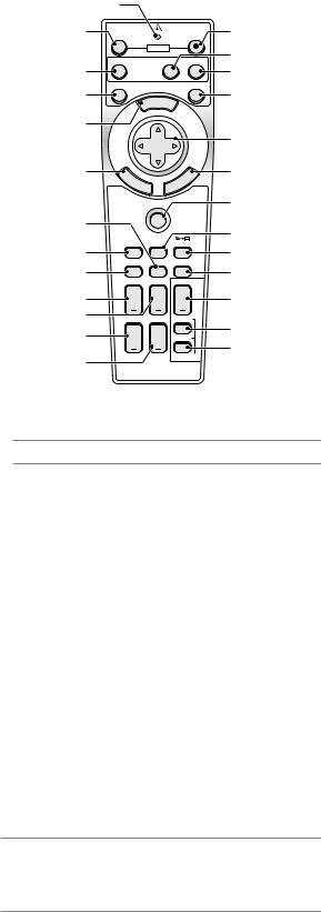
Part Names of the Remote Control
NOTE: If you are using a Macintosh computer, you can click either the right-click or left-click button to activate the mouse.
NOTE: The functions flagged with an asterisk (*) are not available on MT860.
1. Infrared Transmitter
Direct the remote control toward the remote sensor on the projector cabinet.
2. LASER Pointer
Beams a laser light when the LASER button is pressed.
3. Remote Jack
Connect your remote control cable here for wired operation.
4
6 |
OFF |
|
|
|
POWER |
7 |
VIDEO |
RGB |
|
|
|
10 |
AUTO ADJ. |
|
|
MENU |
|
12 |
|
|
SELECT
SELECT
|
LASER |
|
|
|
|
|
R |
|
|
|
|
|
VIEWE |
|
|
ADJ |
|
ON |
RGB |
. |
TOAU |
||
ER |
POW |
|
|
||
|
|
|
|
||
|
|
VIDEO |
|
|
|
|
|
|
|
|
|
|
|
|
OFF |
|
|
3 
2 1
ON |
5 |
VIEWER |
8 |
9
LASER
11
13
REFORM
JP
TEUM -ICP
3D EEZER
14 |
E |
|
|
|
L |
15 |
|
N |
|
|
|
E |
|
|
T |
E |
R |
|
C |
|
|
|
N |
|
|||
|
|
|
CA |
|
|
|
PJ |
16 |
21 |
|
18 |
|
|
|
ASPECT FREEZE 3D REFORM |
||
17 |
|
19 |
HELP |
POINTER |
PIC-MUTE |
20 |
|
22 |
VOLUME MAGNIFY |
SLIDE |
|
23 |
27 |
24 |
ZOOM FOCUS FOLDER |
25 |
28 |
SLIDE |
|
26 |
29 |
LIST |
|
|
4. LED
Flashes when any button is pressed.
5. POWER ON Button
When the main power is on, you can use this button to turn your projector on.
NOTE: To turn on the projector, press and hold the POWER ON button for a minimum of two seconds.
6. POWER OFF Button
You can use this button to turn your projector off.
NOTE: To turn off the projector, press and hold the POWER OFF button for a minimum of two seconds.
7. VIDEO Button
Press this button to toggle between Video and S-Video inputs.
8.RGB Button
Press this button to select RGB 1, RGB 2 or DVI (DIGITAL)* inputs. Each time this button is pressed, the input source will change as follows:
RGB 1 → RGB 2 → DVI (DIGITAL)* → RGB 1 → ...
9. VIEWER Button
Press this button to select the Viewer source.
10. AUTO ADJ Button
Use this button to adjust an RGB source for an optimal picture. Also press and hold this button for a minimum of 2 seconds to enable the Auto Focus* or Auto Wall Color Correction* function. See page E-20 or 22.
11. LASER Button
Press and hold this button to activate the laser pointer. When lit, you can use the laser to draw your audience's attention to a red dot that you can place on any object.
12. MENU Button
Displays the menu for various settings and adjustments.
13. SELECT (Mouse) Button
When you are in the Computer mode, these buttons work as a computer mouse.
When you are in the Projector mode, which is indicated by lighting the PJ button. See page E-24.
: Use these buttons to select the menu of the item you wish to adjust.
: Use these buttons to change the level of a selected menu item. A press of the button executes the selection.
When the pointer is displayed, these buttons move the pointer. When the pointer is not displayed, these buttons are for adjusting the image.
14. ENTER (Left Click) Button
When you are in the Computer mode, this button works as the mouse left button. When this button is pressed and held for a minimum of 2 seconds, the drag mode is set. When you are in the Projector mode, which is indicated by lighting the PJ button: Use this button to enter your menu selection. It works the same way as the ENTER button on the cabinet. See page E-7.
15. CANCEL (Right Click) Button
When you are in the Computer mode, this button works as the mouse right button. When you are in the Projector mode, which is indicated by lighting the PJ button: Press this button to exit the Menus. It works the same way as the CANCEL button on the cabinet. See page E-7.
16. PJ Button
Press this button to switch the SELECT, CANCEL, and ENTER buttons between the Projector mode (lit red) and the Computer mode. Press this button or any one of the POWER ON/OFF, MENU, ASPECT, 3D REFORM, HELP, POINTER, MAGNIFY, VIEWER, FOLDER LIST or SLIDE LIST buttons to switch to the Projector mode and the PJ button lights red. To switch back to the Computer mode, press the PJ button again. See page E-24.
17. ASPECT Button
Press this button to display the Aspect Ratio select screen. See page E-38.
18. FREEZE Button
This button will freeze a picture. Press again to resume motion.
19. 3D REFORM Button
Press this button to enter 3D Reform to correct the keystone (trapezoidal) distortion, and make the image square. See page E-20.
20. HELP Button
Provides the online help or the set information.
21. POINTER Button
Press this button to display one of the eight pointers; press again to
hide the pointer.You can move your pointer icon to the area you want on the screen using the Select button. See page E-25.
E-9
6
7
10
12
14
21
17
20
23
24
25
26
4
OFF |
ON |
|
POWER |
VIDEO |
RGB VIEWER |
AUTO ADJ. |
LASER |
|
MENU |
SELECT
E |
|
|
|
L |
N |
|
|
|
E |
T |
E |
R |
|
C |
|
N |
|||
|
|
CA |
|
|
PJ
ASPECT |
FREEZE 3D REFORM |
|
HELP |
POINTER |
PIC-MUTE |
VOLUME |
MAGNIFY |
SLIDE |
ZOOM |
FOCUS |
FOLDER |
|
|
SLIDE |
|
|
LIST |
5
8
9
11
13
15
16
18
19
22
27
28
29
22. PICTURE MUTE Button
This button turns off the image and sound for a short period of time. Press again to restore the image and sound.
NOTE: When the menu is displayed, a press of this button mutes an image and sound without turning off the menu.
23. VOLUME (+)(–) Button
Press (+) to increase the volume and (–) to decrease it.
24. MAGNIFY (+)(–) Button
Use this button to adjust the image size up to 400%. When the pointer is displayed, the image is magnified about the center of the pointer. When the image is magnified, the pointer is changed to the magnifying icon.
When the pointer is not displayed, the image is magnified about the center of the screen. See page E-25.
25.ZOOM (+)(–) Button Zoom the lens in and out.
26.FOCUS (+)(–) Button Adjust the lens focus.
27.SLIDE (+)(–) Button
Press (+) to select the next folder or slide and (–) to select the previous folder or slide. See page E-29.
28. FOLDER LIST Button
Press this button to select Viewer source to display a list of folders included in a PC card. See page E-29.
29. SLIDE LIST Button
Press this button to select Viewer source to display a list of slides included in a PC card. See page E-29.
NOTE: The default is the Computer mode, which allows you to use the SELECT, CANCEL, and ENTER buttons as your computer mouse. When the POWER ON/ OFF, MENU, ASPECT, 3D REFORM, HELP, POINTER, MAGNIFY, VIEWER, FOLDER LIST, or SLIDE LIST button is pressed, the PJ button lights red to indicate that you are in the Projector mode. If no buttons are pressed within 60 seconds, the light goes out and the Projector mode is canceled.
E-10
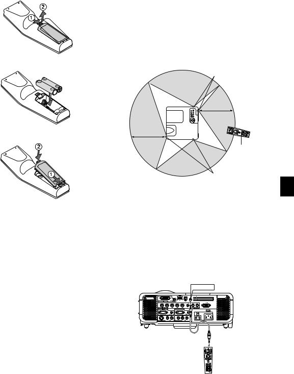
Battery Installation
1. Press firmly and slide the battery cover off.
2.Remove both old batteries and install new ones (AA). Ensure that you have the batteries' polarity (+/-) aligned correctly.
3.Slip the cover back over the batteries until it snaps into place. Do not mix different types of batteries or new and old batteries.
Remote Control Precautions
•Handle the remote control carefully.
•If the remote control gets wet, wipe it dry immediately.
•Avoid excessive heat and humidity.
•If you will not be using the remote control for a long time, remove the batteries.
•Do not place the batteries upside down.
•Do not use new and old batteries together, or use different types of batteries together
Operating Range for Wireless Remote Control
Remote sensor on the projector cabinet
7m/22 feet
7m/22 feet
Remote control
Remote sensor on the projector cabinet
Note on Remote Control Operation:
If you press and hold the SELECT button while installing new batteries, the remote control may fail to work properly.
Should this happen, remove the batteries and then install them again without touching the SELECT button.
•The infrared signal operates by line-of-sight up to a distance of about 22 feet/7 m and within a 60-degree angle of the remote sensor on the projector cabinet.
•The projector will not respond if there are objects between the remote control and the sensor, or if strong light falls on the sensor. Weak batteries will also prevent the remote control from properly operating the projector.
Using the Remote Control in Wired Operation
Connect one end of the supplied remote cable to the REMOTE mini jack and the other end to the remote jack on the remote control.
REMOTE
E-11

INSTALLATION AND CONNECTIONS
This section describes how to set up your projector and how to connect video and audio sources.
1
2
Your projector is simple to set up and use. But before you get started, you must first:
zSet up a screen and the projector.
xConnect your computer or video equipment to the projector. See page E-14 – 17.
cConnect the supplied power cable. See page E-17.
NOTE: Ensure that the power cable and any other cables are disconnected before moving the projector. When moving the projector or when it is not in use, cover the lens with the lens cap.
To the wall outlet.
3
Setting Up the Screen and the Projector
Selecting a Location
The further your projector is from the screen or wall, the larger the image. The minimum size the image can be is approximately 25" (0.64 m) measured diagonally when the projector is roughly 39.4 inches (1.0 m) from the wall or screen. The largest the image can be is 500" (12.7 m) when the projector is about 614.2 inches (15.6 m) from the wall or screen. Use the drawing below as a guide.
|
|
|
|
|
|
|
|
|
|
Screen |
|
|
|
|
|
|
|
|
|
|
|
|
|
|
609. |
|
size |
|
|
|
|
|
|
|
|
|
|
|
406. |
|
6(W)X457. (Unit: |
|
|
|
|||
|
|
|
|
|
|
|
7(W)X365. |
2(H)/240(W)X180(H) |
|
|
|||||
|
|
|
|
|
|
|
|
487. |
|
|
|
cm/inch) |
|
|
|
|
|
|
|
|
|
|
|
|
8(H)/192(W)X144(H) |
|
|
||||
|
|
|
|
|
|
365. |
4(W)X304. |
|
|
||||||
|
|
|
|
|
|
|
8(W)X274. |
8(H)/160(W)X120(H) |
|
300" |
|||||
|
|
|
|
|
304. |
|
|
|
3(H)/144(W)X108(H) |
|
240" |
|
|||
|
|
|
|
|
8(W)X228. |
|
|
|
|
|
200" |
|
|||
|
|
|
|
|
|
|
|
6(H)/120(W)X90(H) |
|
|
|
||||
|
|
|
|
243. |
|
|
|
|
180" |
|
|||||
|
|
|
|
8(W)X182. |
|
|
|
|
|
|
|
|
|
||
|
|
|
|
2(W)X152. |
9(H)/96(W)X72(H) |
|
|
|
|
|
|
||||
|
|
203. |
|
|
|
|
|
|
|
|
|
|
|
||
|
|
|
6(W)X121.4(H)/80(W)X60(H) |
|
|
|
|
150" |
|
|
|||||
|
|
162. |
|
9(H)/64(W)X48(H) |
|
|
|
|
|
|
|
||||
|
|
9(W)X91. |
|
|
|
120" |
|
|
|
||||||
|
|
121. |
|
4(H)/48(W)X36(H) |
|
|
|
|
|
|
|
|
|||
|
|
3(W)X61. |
|
|
|
|
100" |
|
|
|
|||||
TELE: |
81. |
0(H)/32(W)X24(H) |
|
|
|
|
|
|
|
|
|
||||
61. |
|
|
|
|
|
|
|
|
|
80" |
|
|
|
||
|
0(W)X45. |
|
|
|
|
|
|
|
|
|
|
|
|||
|
|
|
|
|
|
|
|
|
|
|
|
|
|
||
|
50. |
7(H)/24(W)X18(H) |
|
|
|
|
60" |
|
|
|
|
||||
|
8(W)X38. |
|
|
|
|
|
|
|
|
|
|
|
|||
|
|
|
|
|
|
|
|
|
|
|
|
|
|
||
|
|
1(H)/20(W)X15(H) |
|
|
|
40" |
|
|
|
|
|
|
|||
|
|
|
|
Lens |
|
|
|
30" |
|
|
|
|
|
|
|
|
|
|
|
center |
|
25" |
|
|
|
|
|
|
|
||
|
|
|
|
|
|
|
|
|
|
|
|
|
|||
|
|
|
|
|
|
|
|
|
|
|
|
|
|
||
|
|
|
|
|
|
|
|
.0 |
|
|
|
|
|
|
|
|
|
|
|
|
|
|
|
1 |
.1 |
|
|
|
|
|
|
|
|
|
|
|
|
|
|
|
1 |
|
.4 |
.1 |
|
|
|
|
|
|
|
|
|
|
|
|
|
|
1 |
.8 |
|
|
|
|
|
|
|
|
|
|
|
|
|
|
|
2 |
.5 |
|
|
|
|
|
|
|
|
|
|
|
|
|
|
|
2 |
.3 |
|
|
|
|
|
|
|
|
|
|
|
|
|
|
|
3 |
|
|
|
|
|
|
|
|
|
|
|
|
|
|
|
|
4 |
Screen Size
.3 |
.4 |
.1 |
.5 |
|
6 |
.6 |
|||
5 |
|
7 |
8 |
|
|
|
|
|
10 |
WARNING: To avoid premature lamp failure, do not tilt the front of the projector up or down by more than 15° from level.
m) (Unit: Distance
E-12
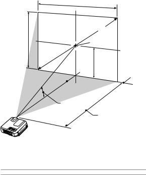
Throw Distance and Screen Size
The following shows the proper relative positions of the projector and screen. Refer to the table to determine the position of installation.
Distance Chart
Screen Width
Screen Diagonal
Screen Height |
Screen center |
(B)
Screen Bottom
 Lens Center
Throw Angle ( )
Throw Distance (C)
B = Vertical distance between lens center and screen center C = Throw distance
α = Throw angle
NOTE: Distances may vary +/-5%.
|
Screen Size |
|
B |
|
C |
|
|
α |
|
|
|
Diagonal |
Width |
Height |
|
Wide – Tele |
Wide – Tele |
|
|
||||
inch |
inch |
inch |
inch |
|
inch |
degree |
|
|
|||
25 |
20 |
15 |
8.0 |
––– |
- |
39.6 |
––– |
- |
10.7 |
|
|
30 |
24 |
18 |
9.0 |
35.1 |
- |
47.8 |
14.4 |
- |
10.7 |
|
|
40 |
32 |
24 |
12.0 |
47.4 |
- |
64.4 |
14.2 |
- |
10.5 |
|
|
60 |
48 |
36 |
18.0 |
72.1 |
- |
97.6 |
14.0 |
- |
10.4 |
|
|
67 |
54 |
40 |
20.0 |
80.7 |
- |
109.2 |
14.0 |
- |
10.4 |
|
|
72 |
58 |
43 |
22.0 |
86.9 |
- |
117.5 |
14.0 |
- |
10.4 |
|
|
80 |
64 |
48 |
24.0 |
96.8 |
- |
130.8 |
13.9 |
- |
10.4 |
|
|
84 |
67 |
50 |
25.0 |
101.7 |
- |
137.4 |
13.9 |
- |
10.4 |
|
|
90 |
72 |
54 |
27.0 |
109.1 |
- |
147.4 |
13.9 |
- |
10.4 |
|
|
100 |
80 |
60 |
30.0 |
121.4 |
- |
164.0 |
13.9 |
- |
10.4 |
|
|
120 |
96 |
72 |
36.0 |
146.1 |
- |
197.2 |
13.8 |
- |
10.3 |
|
|
150 |
120 |
90 |
45.0 |
183.1 |
- |
246.9 |
13.8 |
- |
10.3 |
|
|
180 |
144 |
108 |
54.0 |
220.1 |
- |
296.7 |
13.8 |
- |
10.3 |
|
|
200 |
160 |
120 |
60.0 |
244.8 |
- |
329.9 |
13.8 |
- |
10.3 |
|
|
210 |
168 |
126 |
63.0 |
257.1 |
- |
346.5 |
13.8 |
- |
10.3 |
|
|
240 |
192 |
144 |
72.0 |
294.1 |
- |
396.3 |
13.8 |
- |
10.3 |
|
|
261 |
209 |
157 |
78.0 |
320.0 |
- |
431.1 |
13.7 |
- |
10.3 |
|
|
270 |
216 |
162 |
81.0 |
331.1 |
- |
446.0 |
13.7 |
- |
10.3 |
|
|
300 |
240 |
180 |
90.0 |
368.1 |
- |
495.8 |
13.7 |
- |
10.3 |
|
|
350 |
280 |
210 |
105.0 |
429.8 |
- |
578.7 |
13.7 |
- |
10.3 |
|
|
400 |
320 |
240 |
120.0 |
491.5 |
- |
––– |
13.7 |
- |
––– |
|
|
450 |
360 |
270 |
135.0 |
553.2 |
- |
––– |
13.7 |
- |
––– |
|
|
500 |
400 |
300 |
150.0 |
614.8 |
- |
––– |
13.7 |
- |
––– |
|
|
|
|
|
|
|
|
|
|
|
|
|
|
|
Screen Size |
|
B |
|
C |
|
|
α |
|
|
|
Diagonal |
Width |
Height |
|
Wide – Tele |
Wide – Tele |
|
|
||||
mm |
mm |
mm |
mm |
|
mm |
degree |
|
|
|||
635 |
508 |
381 |
191 |
––– |
- |
1005 |
––– |
- 10.7 |
|
|
|
762 |
610 |
457 |
229 |
891 |
- |
1215 |
14.4 |
- |
10.7 |
|
|
1016 |
813 |
610 |
305 |
1204 |
- |
1636 |
14.2 |
- |
10.5 |
|
|
1524 |
1219 |
914 |
457 |
1831 |
- |
2479 |
14.0 |
- |
10.4 |
|
|
1702 |
1361 |
1021 |
511 |
2050 |
- |
2774 |
14.0 |
- |
10.4 |
|
|
1829 |
1463 |
1097 |
549 |
2207 |
- |
2985 |
14.0 |
- |
10.4 |
|
|
2032 |
1626 |
1219 |
610 |
2458 |
- |
3322 |
13.9 |
- |
10.4 |
|
|
2134 |
1707 |
1280 |
640 |
2583 |
- |
3490 |
13.9 |
- |
10.4 |
|
|
2286 |
1829 |
1372 |
686 |
2771 |
- |
3743 |
13.9 |
- |
10.4 |
|
|
2540 |
2032 |
1524 |
762 |
3084 |
- |
4165 |
13.9 |
- |
10.4 |
|
|
3048 |
2438 |
1829 |
914 |
3711 |
- |
5007 |
13.8 |
- |
10.3 |
|
|
3810 |
3048 |
2286 |
1143 |
4651 |
- |
6272 |
13.8 |
- |
10.3 |
|
|
4572 |
3658 |
2743 |
1372 |
5591 |
- |
7536 |
13.8 |
- |
10.3 |
|
|
5080 |
4064 |
3048 |
1524 |
6217 |
- |
8379 |
13.8 |
- |
10.3 |
|
|
5334 |
4267 |
3200 |
1600 |
6531 |
- |
8800 |
13.8 |
- |
10.3 |
|
|
6096 |
4877 |
3658 |
1829 |
7471 |
- 10064 |
13.8 |
- |
10.3 |
|
|
|
6629 |
5304 |
3978 |
1989 |
8129 |
- 10949 |
13.7 |
- |
10.3 |
|
|
|
6858 |
5486 |
4115 |
2057 |
8410 |
- 11328 |
13.7 |
- |
10.3 |
|
|
|
7620 |
6096 |
4572 |
2286 |
9350 |
- 12593 |
13.7 |
- |
10.3 |
|
|
|
8890 |
7112 |
5334 |
2667 |
10917 |
- 14700 |
13.7 |
- |
10.3 |
|
|
|
10160 |
8128 |
6096 |
3048 |
12484 |
- |
––– |
13.7 |
- ––– |
|
|
|
11430 |
9144 |
6858 |
3429 |
14050 |
- |
––– |
13.7 |
- ––– |
|
|
|
12700 |
10160 |
7620 |
3810 |
15617 |
- |
––– |
13.7 |
- ––– |
|
|
|
WARNING
*Installing your projector on the ceiling must be done by a qualified technician. Contact your NEC dealer for more information.
*Do not attempt to install the projector yourself.
•To avoid premature lamp failure, do not tilt the front of the projector up or down by more than 15° from level.
•Only use your projector on a solid, level surface. If the projector falls to the ground, you can be injured and the projector severely damaged.
•Do not use the projector where temperatures vary greatly. The projector must be used at temperatures between 32˚F (0˚C) and 95˚F (35˚C).
•Do not expose the projector to moisture, dust, or smoke. This will harm the screen image.
•Ensure that you have adequate ventilation around your projector so heat can dissipate. Do not cover the vents on the side or the front of the projector.
Reflecting the Image
Using a mirror to reflect your projector's image enables you to enjoy a much larger image. Contact your NEC dealer if you need a mirror. If you're using a mirror and your image is inverted, use the MENU and SELECT buttons on your projector cabinet or buttons on your remote control to correct the orientation. (See page E-44.)
E-13

Making Connections
NOTE: When using with a notebook PC, be sure to connect between the projector and the notebook PC before turning on the power to the notebook PC. In most cases signal cannot be output from RGB output unless the notebook PC is turned on after connecting with the projector.
*If the screen goes blank while using your remote control, it may be the result of the computer's screen-saver or power management software.
*If you accidentally hit the POWER button on the remote control, wait 90 seconds and then press the POWER button again to resume.
When Viewing a DVI Digital Signal*:
To project a DVI digital signal, be sure to connect the PC and the projector using a DVI-D signal cable (not supplied) before turning on your PC or projector. Turn on the projector first and select DVI (DIGITAL) from the source menu before turning on your PC.
Failure to do so may not activate the digital output of the graphics card resulting in no picture being displayed. Should this happen, restart your PC. Do not disconnect the DVI-D signal cable while the projector is running. If the signal cable has been disconnected and then re-connected, an image may not be correctly displayed. Should this happen, restart your PC.
NOTE: The DVI connector is not available on MT860.
NOTE:
•Use the DVI-D cable compliant with DDWG (Digital Display Working Group) DVI (Digital Visual Interface) revision 1.0 standard. The DVI-D cable should be within 5 m (196") long.
•The DVI (DIGITAL) connector accepts VGA (640x480), SVGA (800x600), 1152x864, XGA (1024x768) and SXGA (1280x1024 @ up to 60Hz).
Connecting Your PC or Macintosh Computer
DVI IN
RGB 2 IN |
RGB 1 IN
IN


RGB signal cable (supplied)  To mini D-Sub 15-pin connec-
tor on the projector. It is recommended that you use a commercially available distribution amplifier if connecting a signal cable longer than the supplied one.
 PHONE
PHONE
IBM VGA or Compatibles (Notebook type) or Macintosh (Notebook type)
Connecting your PC or Macintosh computer to your projector will enable you to project your computer's screen image for an impressive presentation.
To connect to a PC or Macintosh, simply:
1.Turn off the power to your projector and computer.
2.Use the supplied signal cable to connect your PC or Macintosh to the projector.
3.Turn on the projector and the computer.
4.If the projector goes blank after a period of inactivity, it may be caused by a screen saver installed on the computer you've connected to the projector.
DVI-D cable (not supplied)
Audio cable (not supplied)
IBM PC or Compatibles (Desktop type) or Macintosh (Desktop type)
 PHONE
PHONE
NOTE: For older Macintosh, use a commercially available pin adapter (not supplied) to connect to your Mac's video port.
Connecting to RGB 2 IN connectors
Use a BNC 5 cable to connect your PC and the RGB 2 IN connectors on your projector.
Connecting Your PC with a DVI Connector*
Use a DVI-D signal cable (not supplied) to connect a DVI connector of your PC to the projector.
NOTE: The MT1065/MT1060/MT860 is not compatible with video decoded outputs of NEC ISS-6020 and ISS-6010.
E-14

To connect SCART output (RGB)
Before connections: An exclusive SCART adapter (ADP-SC1) and a commercially available SCART cable are required for this connection.
NOTE:
•Audio signal is not available for this connection.
•The RGB IN 2 connector does not support Plug & Play.
Video equipment |
Projector |
such as DVD player |
|
RGB 1 IN |
To RGB IN 1
Commercially available Female |
ADP-SC1 |
SCART cable |
|
1.Turn off the power to the projector and your video equipment.
2.Use the NEC ADP-SC1 SCART adapter and a commercially available SCART cable to connect the RGB 1 input of your projector and a SCART output (RGB) of your video equipment.
3.Turn on the power to the projector and your video equipment.
4.Use the RGB 1 button on the remote control to select the RGB 1 input.
5.Press the MENU button on the remote control to display the menu.
6.From the Advanced menu, select [Projector Options] → [Setup] → [Page 3] → [Signal Select RGB1] → [Scart].
SCART is a standard European audio-visual connector for TVs, VCRs and DVD players. It is also referred to as Euro-connector.
NOTE: The ADP-SC1 SCART adapter is obtainable from your NEC dealer in Europe. Contact your NEC dealer in Europe for more information.
Connecting an External Monitor
RGB OUT
LINE IN
 PHONE
PHONE
You can connect a separate, external monitor to your projector to simultaneously view on a monitor the RGB analog image you're projecting. To do so:
1.Turn off the power to your projector, monitor and computer.
2.Use a 15-pin cable to connect your monitor to the RGB OUT (Mini D- Sub 15 pin) connector on your projector.
3.Turn on the projector, monitor and the computer.
NOTE:
•The RGB OUT connector outputs RGB signal during idle mode (See page E- 45). When the projector goes into idle mode, the image on an external monitor disappears for a moment. Note that the RGB OUT connector will not output RGB signal during Standby mode.
•When the projector is in the Idle mode, the image may not be correctly displayed while the cooling fans are running immediately after turning on or off the power. Note that the RGB OUT connector will not output RGB signal during Standby mode.
•Daisy chain connection is not possible.
E-15

Connecting Your DVD Player
Optional 15-pin-to-RCA (female) 3 cable (ADP-CV1)
RGB 2
2 IN
IN

RGB 1 IN |
RCA(female)-to-BNC(male) adapter (not supplied)
Component video RCA 3 cable (not supplied)
|
|
|
|
|
Audio Equipment |
|
DVD player |
|
|
|
|
|
|
|
|
|
|
|
AUDIO IN |
|
AUDIO OUT |
Component |
L |
R |
|||
L |
R |
Y |
Cb |
Cr |
|
|
|
|
|
|
|
Audio cable |
|
|
|
|
|
|
(not supplied) |
|
You can connect your projector to a DVD player with component output or Video output. To do so, simply:
1.Turn off the power to your projector and DVD player.
2.If your DVD player has the component video (Y,Cb,Cr) output, use a commercially available component video cable (RCAX3) and the optional 15-pin-to-RCA (female) 3 cable to connect your DVD player to the RGB IN1 or IN2 connector on the projector.
For a DVD player without component video (Y,Cb,Cr) output, use common RCA cables (not provided) to connect a composite VIDEO output of the DVD player to the Video Input of the projector.
3. Turn on the projector and DVD player.
NOTE: Refer to your DVD player's owner's manual for more information about your DVD player's video output requirements,
E-16
Connecting Your VCR or Laser Disc Player
VIDEO IN |
S-VIDEO IN |
Video cable (not supplied)
S-video cable (not supplied)
Audio equipment
AUDIO IN


 L R
L R
VCR/ Laser disc player
AUDIO OUT |
|
L |
R |
VIDEO OUT
S-VIDEO OUT
Audio cable (not supplied)
Use common RCA cables (not provided) to connect your VCR, laser disc player or document camera to your projector.
To make these connections, simply:
1.Turn off the power to the projector and VCR, laser disc player or document camera.
2.Connect one end of your RCA cable to the video output connector on the back of your VCR or laser disc player, connect the other end to the Video input on your projector. Use an audio cable (not supplied) to connect the audio from your VCR or laser disc player to your audio equipment (if your VCR or laser disc player has this capability). Be careful to keep your right and left channel connections correct for stereo sound.
3.Turn on the projector and the VCR or laser disc player.
NOTE: Refer to your VCR or laser disc player owner's manual for more information about your equipment's video output requirements.
NOTE: An image may not be displayed correctly when a Video or S-Video source is played back in fast-forward or fast-rewind via a scan converter.
Connecting the Supplied Power Cable
Connect the supplied power cable to the projector.
First connect the supplied power cable's three-pin plug to the AC IN of the projector, and then connect the other plug of the supplied power cable in the wall outlet.
1 2
|
|
|
|
REMOTE |
|
|
|
|
PC CONTROL |
|
|
|
) |
R |
|
|
|
USB(MOUSE/HUB |
L/MONO |
|
|
|
|
AUDIO |
|
|
AUDIO |
V |
|
|
|
|
H |
|
DVI IN |
B/Cb |
|
AUDIO OUT |
|
|
|
G/Y |
|
|
AUDIO |
|
|
|
|
|
|
|
RGB OUT |
|
RGB2 |
IN |
|
|
|
|
|
|
AUDIO |
|
|
|
|
L/MONO |
R |
|
|
|
|
|
AC IN
E-17
 Loading...