


MultiSync LCD2490WUXi2-BK
Table of contents
 Loading...
MultiSync LCD2690WUXi
MultiSync LCD2490WUXi
User’s Manual
2
2

Index
Warning, Caution ........................................................................................................................ English-1
Declaration .................................................................................................................................. English-1
Canadian Department of Communications Compliance Statement............................................ English-2
Declaration of Conformity ........................................................................................................... English-2
Contents ...................................................................................................................................... English-3
Quick Start .................................................................................................................................. English-4
Controls ....................................................................................................................................... English-8
Recommended use ..................................................................................................................... English-13
Specifications - LCD2690WUXi2 ................................................................................................ English-15
Specifications - LCD2490WUXi2 ................................................................................................ English-16
Features ...................................................................................................................................... English-17
Troubleshooting .......................................................................................................................... English-18
Advanced OSD ........................................................................................................................... English-19
Using the Auto Brightness function ............................................................................................. English-26
Using the PICTURE MODE function ........................................................................................... English-27
TCO’03 ........................................................................................................................................ English-28
Manufacturer’s Recycling and Energy Information ..................................................................... English-29
WARNING
TO PREVENT FIRE OR SHOCK HAZARDS, DO NOT EXPOSE THIS UNIT TO RAIN OR MOISTURE. ALSO, DO NOT
USE THIS UNIT'S POLARIZED PLUG WITH AN EXTENSION CORD RECEPTACLE OR OTHER OUTLETS UNLESS
THE PRONGS CAN BE FULLY INSERTED.
REFRAIN FROM OPENING THE CABINET AS THERE ARE HIGH VOLTAGE COMPONENTS INSIDE. REFER
SERVICING TO QUALIFIED SERVICE PERSONNEL.
CAUTION
CAUTION: TO REDUCE THE RISK OF ELECTRIC SHOCK, MAKE SURE POWER CORD IS UNPLUGGED FROM
WALL SOCKET. TO FULLY DISENGAGE THE POWER TO THE UNIT, PLEASE DISCONNECT THE
POWER CORD FROM THE AC OUTLET.DO NOT REMOVE COVER (OR BACK). NO USER
SERVICEABLE PARTS INSIDE. REFER SERVICING TO QUALIFIED SERVICE PERSONNEL.
This symbol warns user that uninsulated voltage within the unit may have sufficient magnitude to cause
electric shock. Therefore, it is dangerous to make any kind of contact with any part inside this unit.
This symbol alerts the user that important literature concerning the operation and maintenance of this unit
has been included. Therefore, it should be read carefully in order to avoid any problems.
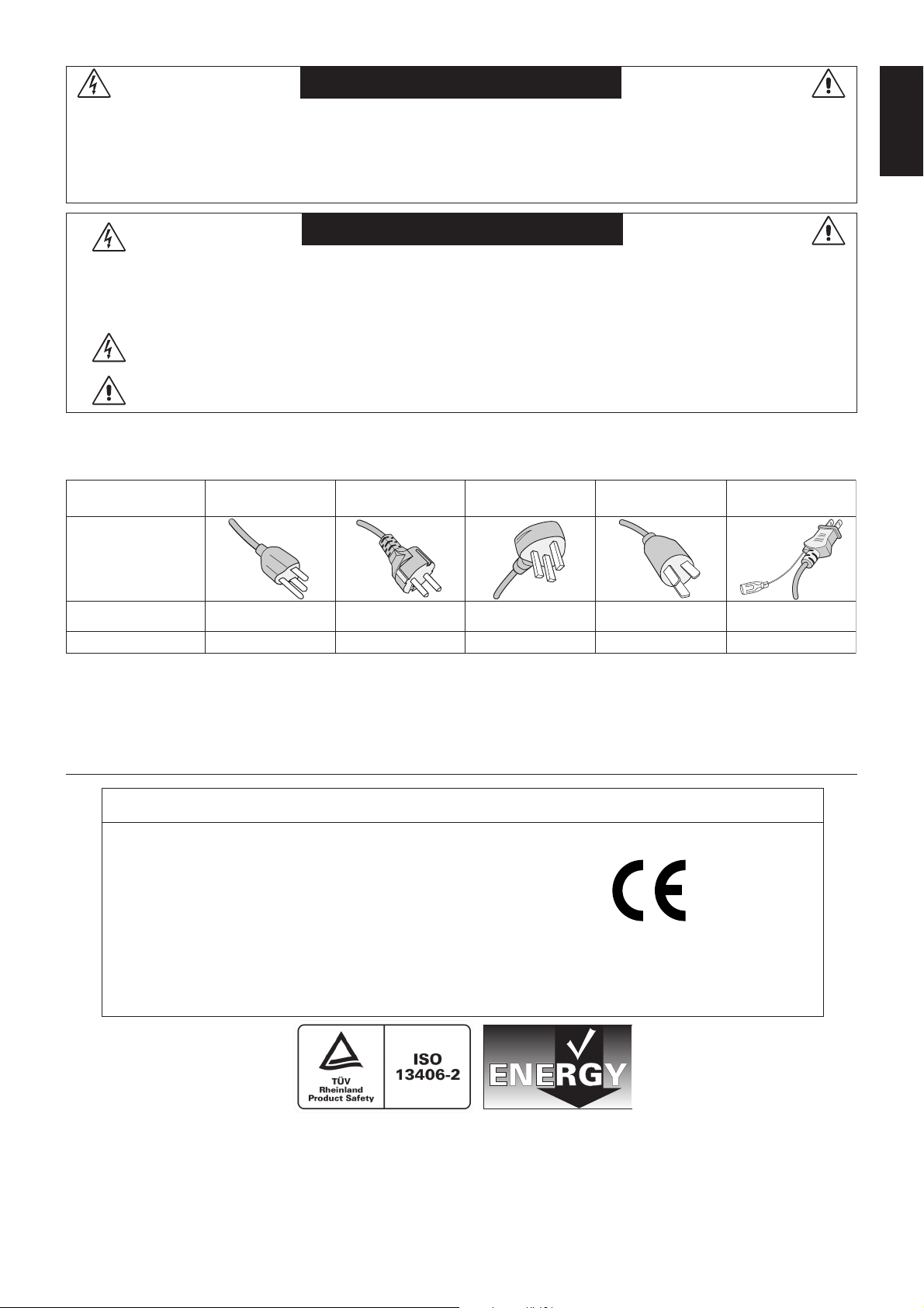
CAUTION: Please use the power cord provided with this display in accordance with the table below. If a power cord is not
supplied with this equipment, please contact your supplier. For all other cases, please use a power cord that matches the
AC voltage of the power outlet and has been approved by and complies with the safety standard of your particular country.
Plug Type North America
European
Continental
U.K. Chinese Japanese
English
Plug Shape
Country
Voltage
*When operating the MultiSync LCD2690WUXi2 or MultiSync LCD2490WUXi2 monitor with its AC 125-240V power supply,
use a power supply cord that matches the power supply voltage of the AC power outlet being used.
NOTE: This product can only be serviced in the country where it was purchased.
U.S.A./Canada U.K. China JapanEU (except U.K.)
120* 230 220 100230
Declaration
Declaration of the Manufacturer
We hereby certify that the color monitor MultiSync
LCD2690WUXi2 (L266RZ) and MultiSync
LCD2490WUXi2 (L246T0) are in compliance with:
Council Directive 2006/95/EC:
– EN 60950-1
Council Directive 2004/108/EC:
– EN 55022
– EN 61000-3-2
– EN 61000-3-3
– EN 55024
and marked with
NEC Display Solutions, Ltd.
4-13-23, Shibaura,
Minato-Ku
Tokyo 108-0023, Japan
Windows is a registered trademark of Microsoft Corporation. NEC is a registered trademark of NEC Corporation.
ENERGY STAR is a U.S. registered trademark.
ErgoDesign is a registered trademark of NEC Display Solutions, Ltd. in Austria, Benelux, Denmark, France, Germany, Italy, Norway, Spain,
Sweden, U.K.
All other brands and product names are trademarks or registered trademarks of their respective owners.
As an ENERGY STAR® Partner, NEC Display Solutions of America, Inc. has determined that this product meets the ENERGY STAR guidelines for
energy efficiency. The ENERGY STAR emblem does not represent EPA endorsement of any product or service.
Adobe® is a registered trademark or trademark of Adobe Systems Incorporated in the U.S. and/or other countries.
English-1
Canadian Department of Communications Compliance Statement
DOC: This Class B digital apparatus meets all requirements of the Canadian Interference-Causing Equipment Regulations.
C-UL: Bears the C-UL Mark and is in compliance with Canadian Safety Regulations according to CAN/CSA C22.2 No. 60950-1.
FCC Information
1. Use the attached specified cables with the MultiSync LCD2690WUXi2 or MultiSync LCD2490WUXi2 color monitor so
as not to interfere with radio and television reception.
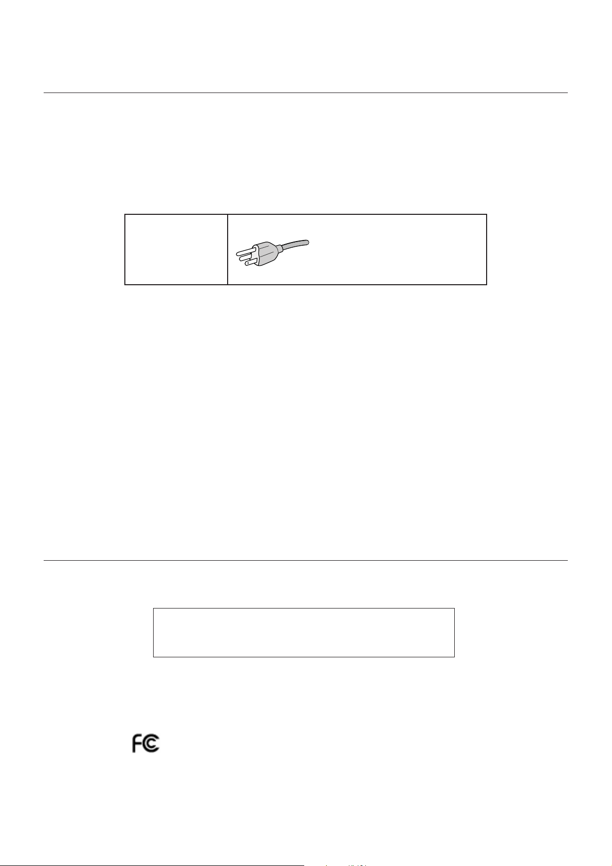
(1) The power supply cord you use must have been approved by and comply with the safety standards of U.S.A.,
and meet the following condition.
Power supply cord Non shield type, 3-conductor
Length 2.0 m
Plug shape
U.S.A
(2) Please use the supplied shielded video signal cable, 15-pin mini D-SUB to DVI-A cable or DVI-D to DVI-D cable.
Use of other cables and adapters may cause interference with radio and television reception.
2. This equipment has been tested and found to comply with the limits for a Class B digital device, pursuant to part 15 of
the FCC Rules. These limits are designed to provide reasonable protection against harmful interference in a residential
installation. This equipment generates, uses, and can radiate radio frequency energy, and, if not installed and used in
accordance with the instructions, may cause harmful interference to radio communications. However, there is no
guarantee that interference will not occur in a particular installation. If this equipment does cause harmful interference
to radio or television reception, which can be determined by turning the equipment off and on, the user is encouraged
to try to correct the interference by one or more of the following measures:
• Reorient or relocate the receiving antenna.
• Increase the separation between the equipment and receiver.
• Connect the equipment into an outlet on a circuit different from that to which the receiver is connected.
• Consult your dealer or an experienced radio/TV technician for help.
If necessary, the user should contact the dealer or an experienced radio/television technician for additional
suggestions. The user may find the following booklet, prepared by the Federal Communications Commission, helpful:
“How to Identify and Resolve Radio-TV Interference Problems.” This booklet is available from the U.S. Government
Printing Office, Washington, D.C., 20402, Stock No. 004-000-00345-4.
Declaration of Conformity
This device complies with Part 15 of FCC Rules. Operation is subject to the following two conditions. (1) This device may not
cause harmful interference, and (2) this device must accept any interference received, including interference that may cause
undesired operation.
U.S. Responsible Party: NEC Display Solutions of America, Inc.
Address: 500 Park Blvd, Suite 1100
Itasca, Illinois 60143
Tel. No.: (630) 467-3000
Type of Product: Display Monitor
Equipment Classification: Class B Peripheral
Models: MultiSync LCD2690WUXi2 (L266RZ)
MultiSync LCD2490WUXi2 (L246T0)
We hereby declare that the equipment specified above conforms
to the technical standards as specified in the FCC Rules.
English-2
Contents
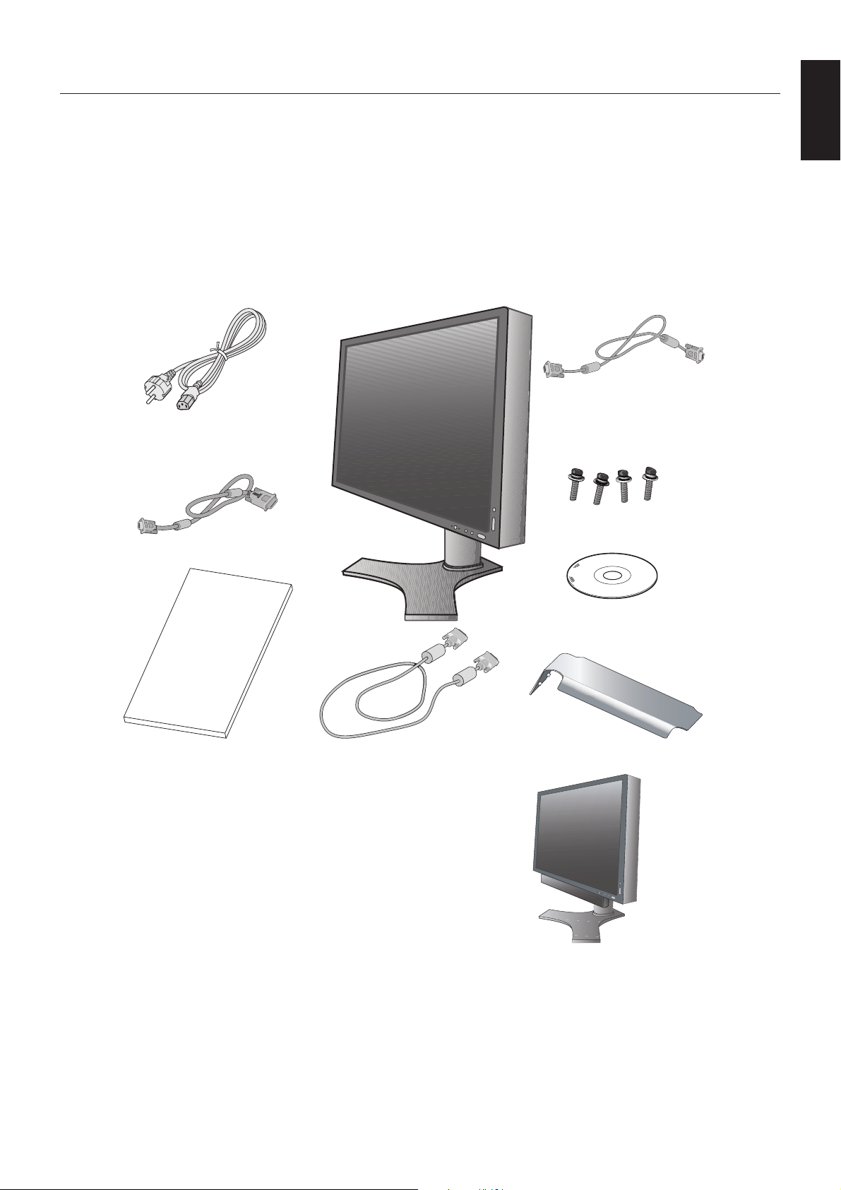
Your new NEC monitor box* should contain the following:
• MultiSync LCD2690WUXi2 or MultiSync LCD2490WUXi2 monitor with tilt/swivel/pivot/height adjust stand
• Power Cord
•Video Signal Cable (15-pin mini D-SUB male to DVI-A)
•Video Signal Cable (DVI-D to DVI-D cable)
•Video Signal Cable (Mini D-SUB 15 pin to Mini D-SUB 15 pin) (For U.S. and China)
• User’s Manual
• CD-ROM
• Cable Cover
• Screw (x 4) (to mount the monitor to a flexible arm (page 7))
Mini D-SUB 15 pin to
Mini D-SUB 15 pin
(Type of power cord included will
Power Cord
depend on the where the LCD
monitor is to be shipped)
(For U.S. and China)
English
15-pin mini D-SUB male to DVI-A
User’s Manual
User’s Manual DVI-D to DVI-D cable Cable Cover
NOTE: This monitor can be equipped with optional
loudspeakers: “MultiSync Sound bar”.
Please ask your dealer or check our website
http://www.necdsiplaysolution.com
Screws
CD-ROM
*
Remember to save your original box and packing material to transport or ship the monitor.
English-3
Quick Start
To attach the LCD monitor to your system, follow these instructions:
1. Turn off the power to your computer.
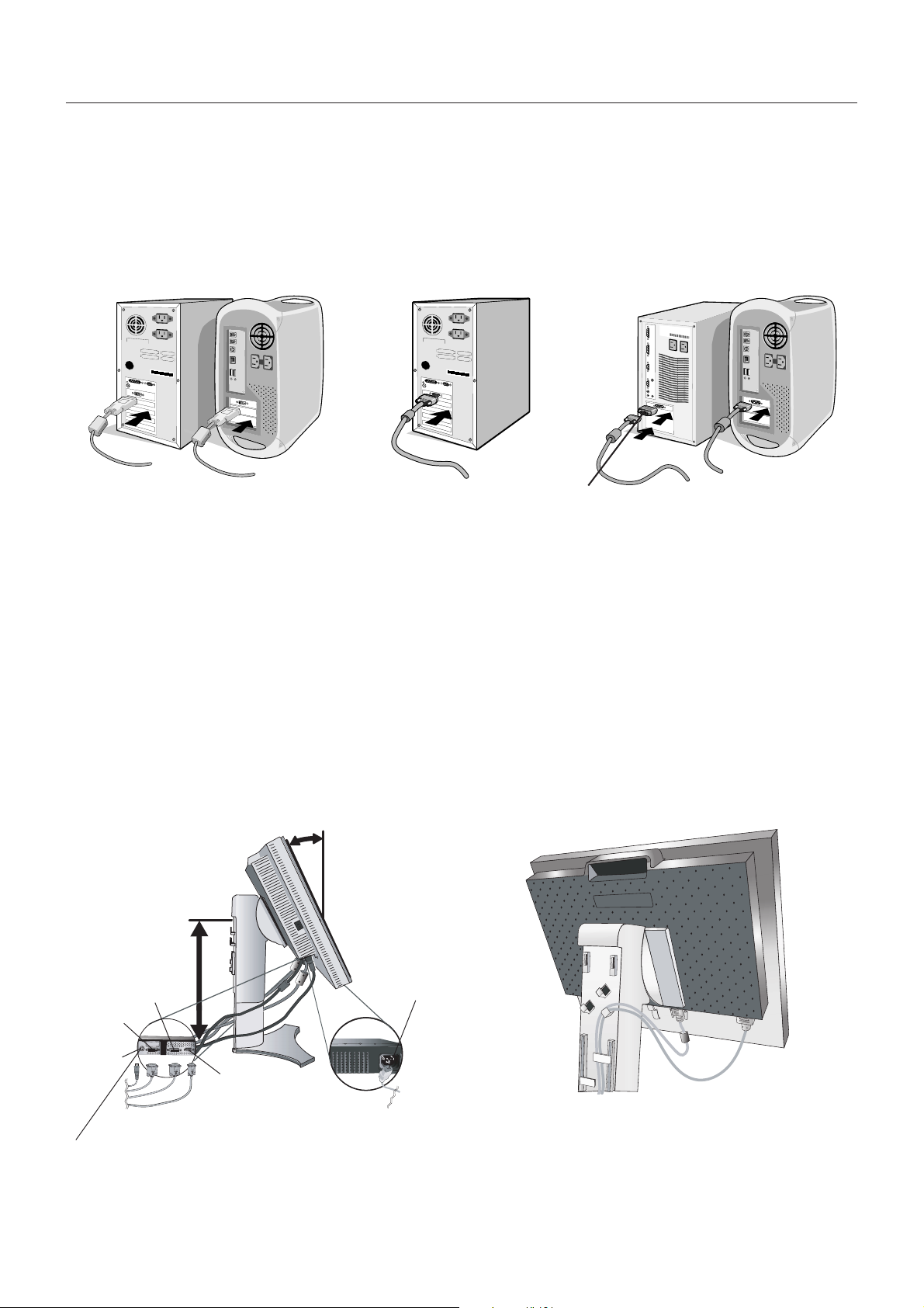
2. For the PC or MAC with DVI digital output: Connect the DVI signal cable to the connector of the display card in your
system (Figure A.1). Tighten all screws.
For the PC with Analog output: Connect the 15-pin mini D-SUB to DVI-A signal cable to the connector of the display
card in your system (Figure A.2).
For the MAC: Connect the Macintosh cable adapter to the computer, then attach the 15-pin mini D-SUB signal cable to
the Macintosh cable adapter (Figure B.1).
Macintosh
Figure A.1 Figure B.1
NOTE: Some Macintosh systems do not require a Macintosh cable adapter.
Figure A.2
Cable Adapter
(not included)
3. Place hands on each side of the monitor to tilt the LCD panel 30-degree angle and lift up to the highest position (Figure C.1).
4. Connect all cables to the appropriate connectors (Figure C.1).
NOTE: Incorrect cable connections may result in irregular operation, damage display quality/components of LCD module
and/or shorten the module’s life.
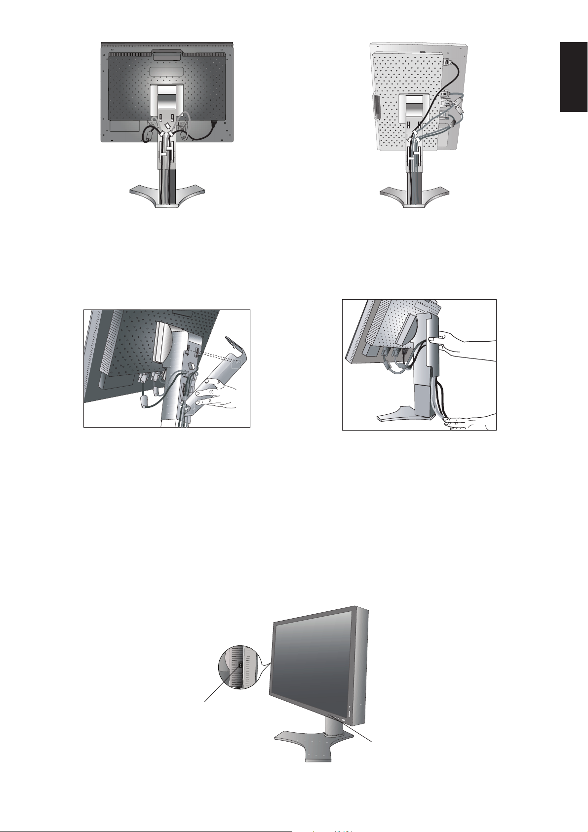
5. To keep the cables neatly organized, place them into the cable management system that is built into the stand.
Place the D-Sub cable (not included for Europe) and the power cable into the specific hooks as indicated (Figure C.2).
Place the DVI cable and the 15-pin mini D-Sub to DVI-A cable into the hooks as indicated (Figure C.3).
When using the monitor in Portrait mode, place the DVI cable and the 15-pin mini D-Sub to DVI-A cable into the hooks as
indicated (Figure C.4).
6. Make sure all cables are resting flat against the stand (Figure C.3).
Please check Tilt, Rise and Lower monitor screen and screen rotation when you manage cables.
30˚ Tilt
Highest
Stand
Position
DVI-I
DVI-D
Power cord
DC-OUT
D-SUB
Figure C.1
NEC optional product attachment.
Do not use this connector unless specified.
Figure C.2
English-4
English
Figure C.3
7. Hold all cables firmly and place the cable cover onto the stand (Figure D.1). To remove the cable cover, lift the cover off
as shown in Figure D.2.
8. Connect one end of the power cord to the AC inlet on the back of the monitor and the other end to the power outlet.
NOTE: Please refer to Caution section of this manual for proper selection of AC power cord.
Figure D.1
9. The Vacation Switch on the left side of the monitor must be turned on. Turn on the monitor with the front power button
(Figure E.1) and the computer.
NOTE: The Vacation Switch is a true on/off switch. If this switch is on the OFF position, the monitor cannot be turned on
using the front button. DO NOT switch on/off repeatedly.
10. No-touch auto adjust automatically adjusts the monitor to optimal settings upon initial setup for most timings. For further
adjustments, use the following OSD controls:
• Auto Contrast (Analog input only)
• Auto Adjust (Analog input only)
Refer to the Controls section of this User’s Manual for a full description of these OSD controls.
NOTE: If you have any problems, please refer to the Troubleshooting section of this User’s Manual.
Figure C.4
Figure D.2
Vacation
Switch
Power Button
Figure E.1
English-5
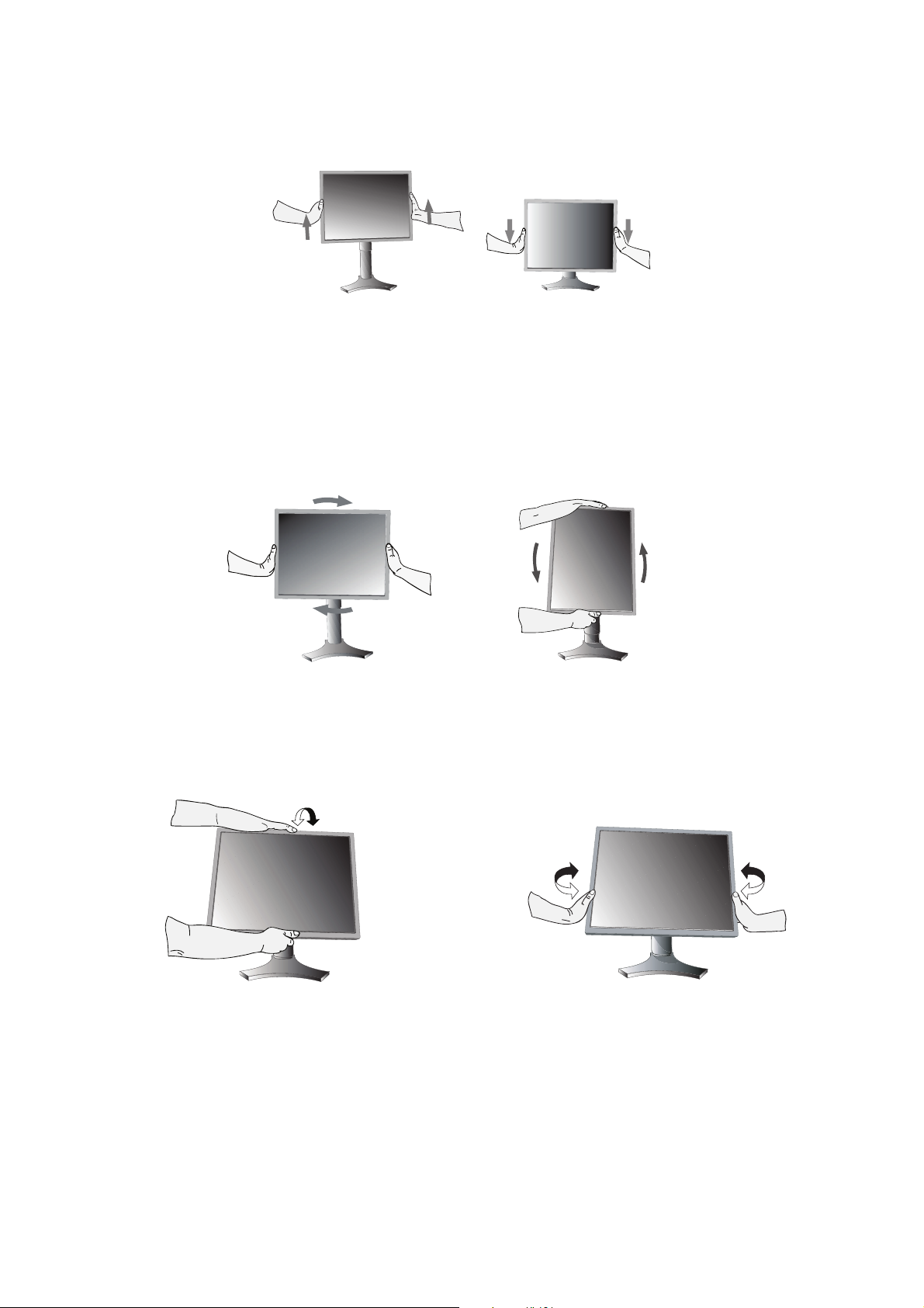
Raise and Lower Monitor Screen
The monitor may be raised or lowered in either Portrait or Landscape mode.
To raise or lower screen, place hands on each side of the monitor and lift or lower to the desired height (Figure RL.1).
NOTE: Handle with care when raising or lowering the monitor screen.
Figure RL.1
Screen Rotation
Before rotating, the screen must be raised to the highest level to avoid knocking the screen on the desk or pinching your
fingers.
To raise the screen, place hands on each side of the monitor and lift up to the highest position (Figure RL.1).
To rotate screen, place hands on each side of the monitor screen and turn clockwise from Landscape to Portrait or counterclockwise from Portrait to Landscape (Figure R.1).
To rotate OSD menu between landscape and portrait, refer to “Controls” section.
Figure R.1
Tilt
Grasp top and bottom sides of the monitor screen with your
hands and adjust the tilt as desired (Figure TS.1).
Figure TS.1
NOTE: Handle with care when tilting the monitor screen.
Swivel
Grasp both sides of the monitor screen with your hands and
adjust the swivel as desired (Figure TS.2).
Figure TS.2
English-6
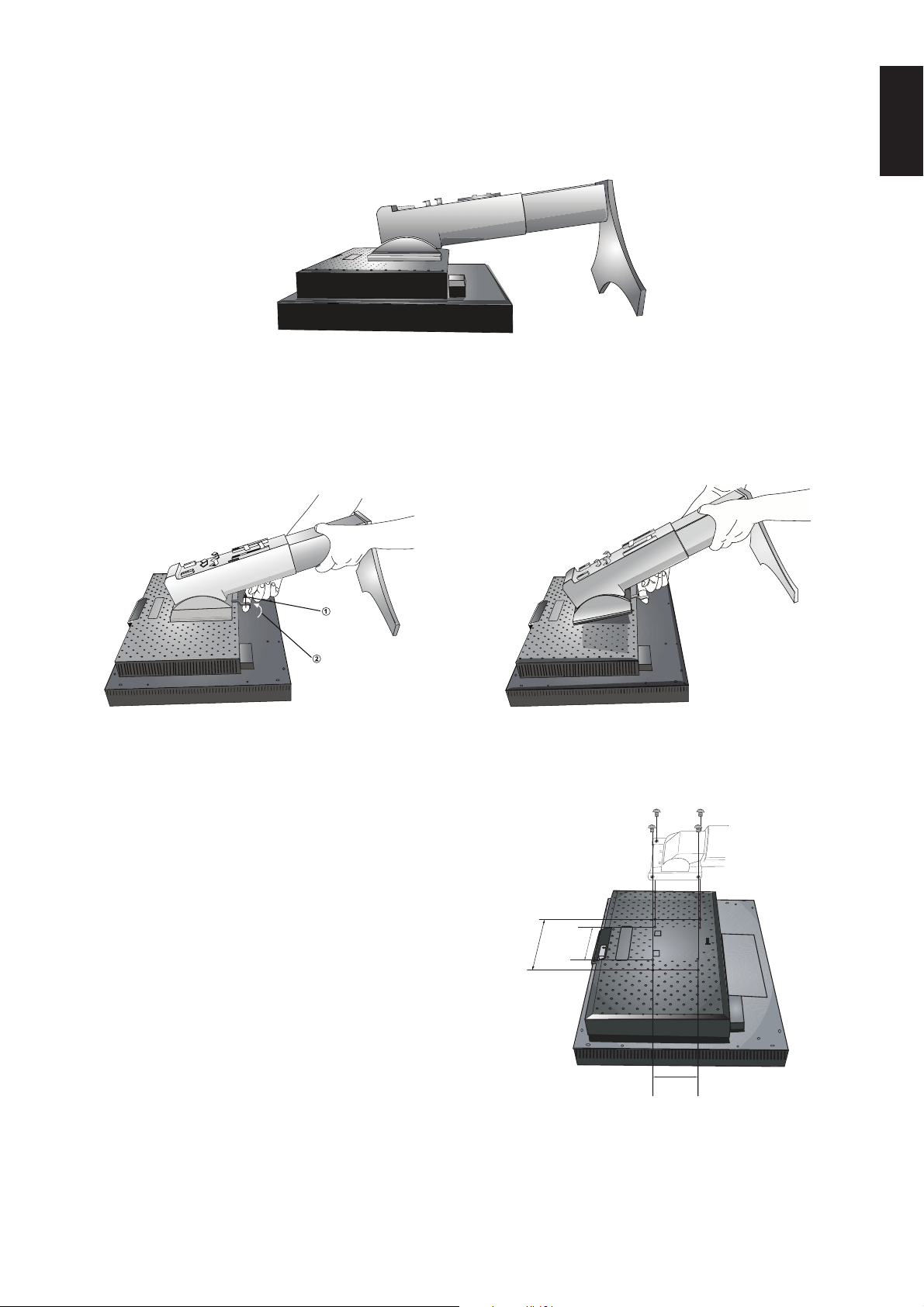
Remove Monitor Stand for Mounting
To prepare the monitor for alternate mounting purposes:
1. Disconnect all cables.
2. Place hands on each side of the monitor and lift up to the highest position.
3. Place monitor face down on a non-abrasive surface (Figure S.1).
Figure S.1
4. Place one hand around the base and one hand on the Quick Release Lever. Move the Quick Release Lever in the direction
indicated by the arrows (Figure S.2).
5. Lift up the bottom of the stand to unhook it from the monitor (Figure S.3). The monitor can now be mounted using an
alternate method. Reverse process to reattach stand.
NOTE: Handle with care when removing monitor stand.
English
Up
Slide
Figure S.2
Flexible Arm Installation
This LCD monitor is designed for use with a flexible arm.
1. Follow the instructions on how Remove Monitor Stand for
Mounting to remove the stand.
2. Using the 4 screws from the stand removal and attach the arm to
the monitor (Figure F.1).
Caution: Use ONLY the screws (4 pcs) that are included when
mounting to avoid damage to the monitor and stand.
To fulfil the safety requirements the monitor must be
mounted to an arm which guaranties the necessary
stability under consideration of the weight of the monitor.
The LCD monitor should only be used with an approved
arm (e.g. GS mark).
When using mounting accessories (e.g. VESA (200 x 100))
other than VESA (100 x 100), use the screws M4 size
(Length: bracket thickness + 10mm).
Figure S.3
200mm
100mm
100mm
Weight of LCD assembly: 9.4 kg (LCD2690WUXi2)
8.7 kg (LCD2490WUXi2)
English-7
Figure F.1
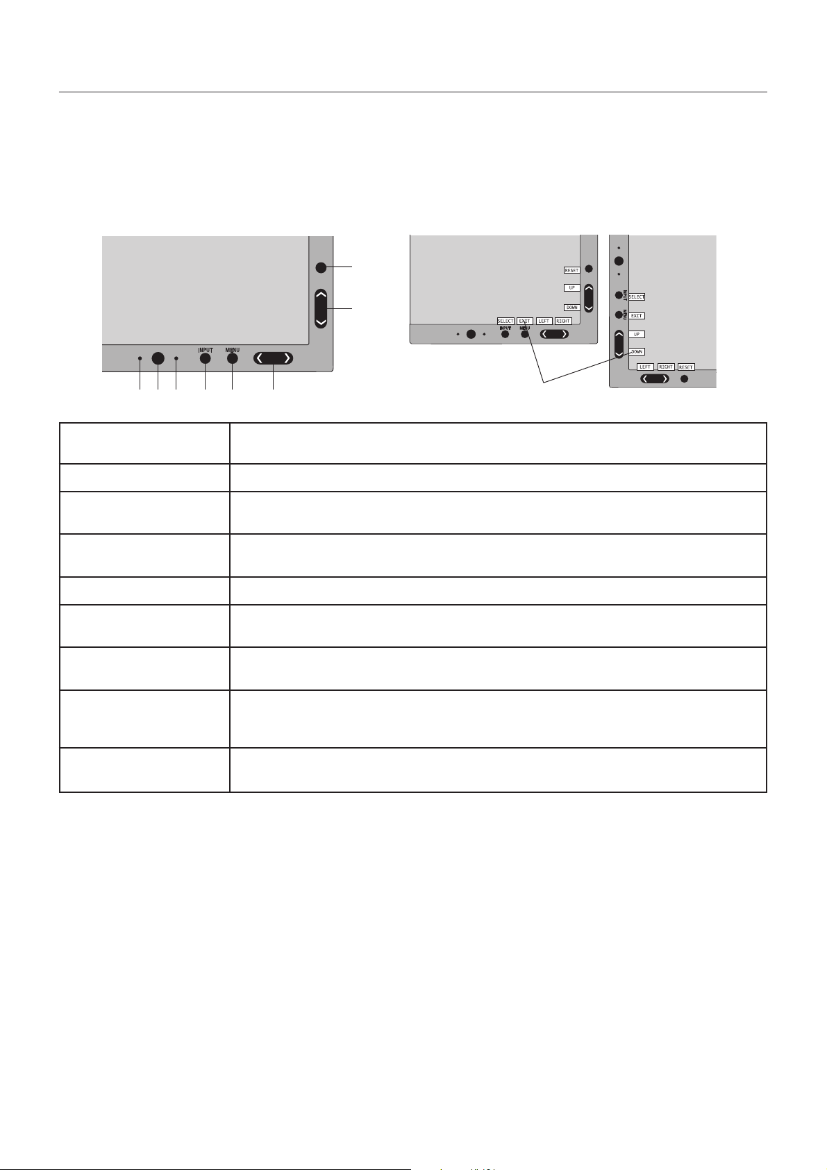
Controls
OSD (On-Screen Display) control buttons on the front of the monitor function
as follows:
To access OSD menu, press the MENU button.
To change signal input, press the SELECT button.
NOTE: OSD must be closed in order to change signal input.
8
7
Landscape
1 2 3 4 5 6
1 AUTO DIMMING SENSOR
2 POWER
3 LED
4 INPUT/SELECT
5 MENU/EXIT
6 LEFT/RIGHT
7 UP/DOWN
8 RESET
9 KEY GUIDE
9
Detects the level of ambient lighting allowing the monitor to make adjustments to various
settings resulting in a more comfortable viewing experience. Do not cover this sensor.
Turns the monitor on and off.
Indicates that the power is on.
Can be changed between blue and green in the Advanced OSD menu.
Enters the OSD Control menu. Enters OSD sub menus.
Changes the input source when not in the OSD Control menu.
Access OSD menu. Exits the OSD sub menu. Exits OSD Control menu.
Navigates to the left or right through the OSD Control menu. You can adjust the brightness
directly (HotKey function ON), while the OSD menu is off.
Navigates up or down through the OSD Control menu. You can adjust the contrast directly
(HotKey function ON), while the OSD menu is off.
Resets the OSD back to factory settings.
When pressed RESET when OSD is not showing, you can select “PICTURE MODE” (page 27),
“ECO MODE” (page 9) and “RESPONSE IMPROVE” (page 23) directly.
The Key Guide appears on screen when the OSD control menu is accessed.
The Key Guide will rotate when the OSD control menu is rotated*.
Portrait
* The “LEFT/RIGHT” and “UP/DOWN” buttons functionality is interchangeable depending on the orientation
(Landscape/Portrait) of the OSD.
SETTING OSD LANGUAGE
• Set the OSD language before using OSD functions.
•To access the “LANGUAGE SELECTION” menu, press control key (LEFT/RIGHT or UP/DOWN or MENU).
• Press the LEFT/RIGHT or UP/DOWN buttons to select the desired OSD language.
•To exit from this OSD menu, press EXIT button.
NOTE: Setting the OSD language is only necessary upon initial setup. The OSD language will stay the same until changed
by the user.
English-8
Loading...