


SPLIT-TYPE AIR CONDITIONERS
INDOOR UNIT
SERVICE MANUAL |
No. OBH529 |
|
Models
MSC-GE20VB - MSC-GE25VB - MSC-GE35VB - MS-GE50VB - MSH-GE50VB -
E1
E1
E1
E1
E1
Outdoor unit service manual MU-GA•VB Series (OB386) MUH-GA•VB Series (OB387) MUX-A•VB Series (OB384) MXZ-A•WV Series (OB319) MU/MUH-GE•VB Series (OBH530)
CONTENTS
1.TECHNICAL CHANGES ··································· 2
2.PART NAMES AND FUNCTIONS····················· 2
3.SPECIFICATION················································ 4
4.NOISE CRITERIA CURVES ······························ 5
5.OUTLINES AND DIMENSIONS ························ 7
6.WIRING DIAGRAM············································ 9
7.REFRIGERANT SYSTEM DIAGRAM ············· 10
8.SERVICE FUNCTIONS ····································11
9.MICROPROCESSOR CONTROL ··················· 14
10.TROUBLESHOOTING····································· 22
11.DISASSEMBLY INSTRUCTIONS···················· 32
PARTS CATALOG (OBB529)
NOTE:
RoHS compliant products have <G> mark on the spec name plate.
1 
 TECHNICAL CHANGES
MSC-GA20VB - E1 MSC-GA25VB - E1 MSC-GA35VB - E1
→MSC-GE20VB - E1
→MSC-GE25VB - E1
→MSC-GE35VB - E1
1. Front panel has been changed.
MS-GA50VB - E1 → MS-GE50VB - E1
1. Indoor fan motor has been changed. (RC4V32-AA  RC4V32-BA)
MSH-GA50VB - E1 → MSH-GE50VB - E1
1. Indoor fan motor has been changed. (RC4V32-AA  RC4V32-BA)
2 
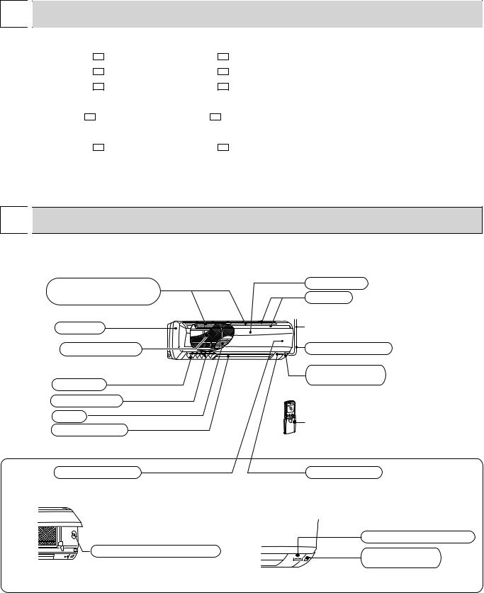
 PART NAMES AND FUNCTIONS
MSC-GE20VB MSC-GE25VB MSC-GE35VB
Air cleaning filter(option) |
Front panel |
|
(White bellows type) |
Air inlet |
|
Panel |
to Breaker |
|
Catechin air filter |
Power supply cord |
|
|
Remote control |
|
Air outlet |
receiving section |
|
|
||
Vertical vanes |
|
|
Fan |
Remote controller |
|
Horizontal vane |
||
|
||
Operation section |
Display section |
|
(When the front panel is opened) |
|
|
Operation indicator lamp |
Emergency operation switch |
Remote control |
|
receiving section |
2
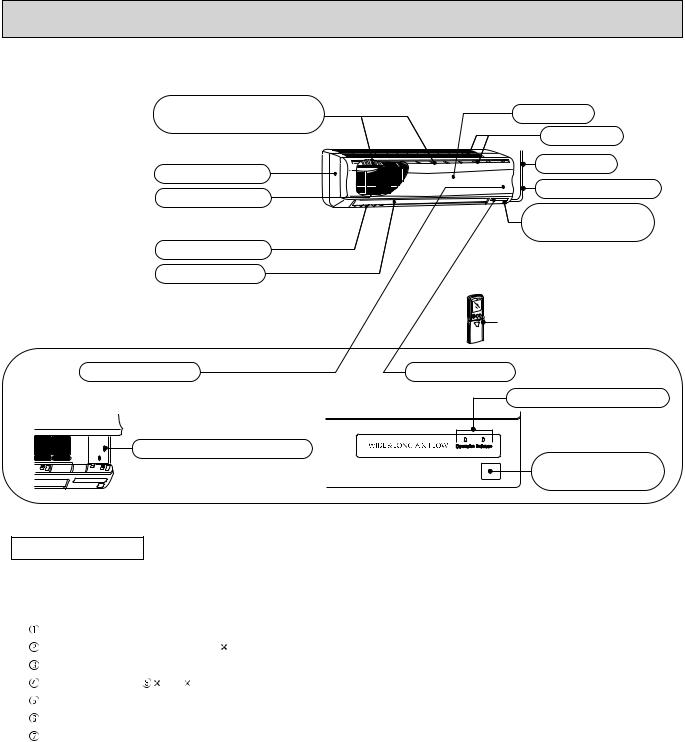
MS-GE50VB MSH-GE50VB
Air cleaning filter (option) |
Front panel |
|
(White bellows type) |
||
Air inlet |
||
|
||
Panel |
To breaker |
|
Power supply cord |
||
Catechin air filter |
||
|
||
|
Remote control |
|
|
receiving section |
|
Vertical vanes |
|
|
Horizontal vane |
|
Remote controller
Operation section |
Display section |
(When the grille is opened) |
Operation indicator lamp |
|
Emergency operation switch
Remote control receiving section
ACCESSORIES
|
|
MSC-GE20VB |
MS-GE50VB |
|
|
MSC-GE25VB |
|
|
|
MSH-GE50VB |
|
|
|
MSC-GE35VB |
|
|
|
|
|
|
Installation plate |
1 |
1 |
|
Installation plate fixing screw 4 25 mm |
5 |
7 |
|
Remote controller holder |
1 |
1 |
|
Fixing screw for 3.5 1.6 mm (Black) |
2 |
2 |
|
Battery (AAA) for remote controller |
2 |
2 |
|
Wireless remote controller |
1 |
1 |
|
Felt tape (Used for left or left-rear piping) |
1 |
1 |
3
3 
 SPECIFICATION
Indoor model |
|
MSC-GE20VB |
|||
Function |
|
Cooling |
Heating |
||
Power supply |
|
Single phase |
|||
|
230 V, 50 Hz |
||||
|
Breaker capacity |
A |
|||
Electrical data |
|
10 |
|||
Running current |
A |
0.17 |
|||
|
|||||
|
Power input |
W |
|
35 |
|
Fan motor |
Power factor |
% |
|
90 |
|
Model |
A |
RC4V19-JA |
|||
Fan motor current |
0.17 |
||||
Dimensions W H D |
mm |
815 278 244 |
|||
Weight |
Air direction |
kg |
|
9 |
|
Special remarks |
m3/h |
|
5 |
||
Air flow (High/Med./Low) |
474/372/276 |
510/420/342 |
|||
Fan speed (High/Med./Low) |
rpm |
900/750/600 |
950/820/700 |
||
|
Sound level (High/Med./Low) |
dB |
36/31/25 |
36/31/25 |
|
|
Fan speed regulator |
|
|
3 |
|
Remote controller model |
|
KM04F |
|||
MSC-GE25VB MSC-GE35VB
Cooling |
|
|
Heating |
Cooling |
|
Heating |
Single phase |
Single phase |
|||||
230 V, 50 Hz |
230 V, 50 Hz |
|||||
|
|
10 |
|
|
10 |
|
|
0.17 |
|
|
0.19 |
|
|
|
|
35 |
|
|
40 |
|
|
|
90 |
|
|
92 |
|
RC4V19-JA |
RC4V19-HA |
|||||
815 |
0.17 |
|
815 |
0.19 |
|
|
278 |
244 |
278 |
244 |
|||
|
|
9 |
|
|
10 |
|
|
|
5 |
|
|
5 |
|
474/384/306 |
588/456/342 |
582/444/324 |
606/498/396 |
|||
36/31/25 |
|
39/32/25 |
40/33/26 |
39/33/26 |
||
900/770/650 |
1,050/870/700 |
930/760/600 |
960/830/700 |
|||
|
|
3 |
|
|
3 |
|
KM04F |
KM04F |
|||||
Indoor model
Function
Power supply
data |
Breaker capacity |
|
Running current |
||
Electrical |
||
Power factor |
||
|
Power input |
|
Fan motor |
Model |
|
Fan motor current |
||
Dimensions W H D |
||
Weight |
|
|
|
Air direction |
|
Special remarks |
Air flow (High/Med./Low) |
|
Sound level (High/Med./Low) Fan speed (High/Med./Low) Fan speed regulator
Remote controller model
|
MS-GE50VB |
|
MSH-GE50VB |
||||
|
Cooling |
|
Cooling |
|
|
Heating |
|
|
Single phase |
|
Single phase |
||||
|
230 V, 50 Hz |
|
230 V, 50 Hz |
||||
A |
|
10 |
|
|
|
10 |
|
A |
|
0.3 |
|
|
|
0.3 |
|
W |
|
60 |
|
|
|
60 |
|
% |
|
87 |
|
|
|
87 |
|
|
RC4V32-BA |
|
RC4V32-BA |
||||
A |
|
0.3 |
|
|
|
0.3 |
|
mm |
1,100 |
325 |
258 |
|
1,100 |
325 |
258 |
kg |
|
16 |
|
|
|
16 |
|
|
|
5 |
|
|
|
5 |
|
/h |
768/642/516 |
|
768/642/516 |
||||
dB |
42/38/34 |
|
|
42/38/34 |
|
||
rpm |
1,070/920/780 |
|
1,070/920/780 |
||||
|
|
3 |
|
|
|
3 |
|
|
KM04B |
|
|
KM04A |
|
||
NOTE: Test conditions are based on ISO 5151. |
Wet-bulb temperature 19°C |
||
Cooling: Indoor |
Dry-bulb temperature 27°C |
||
Outdoor |
Dry-bulb temperature 35°C |
Wet-bulb temperature 24°C |
|
Heating: Indoor |
Dry-bulb temperature 20°C |
Wet-bulb temperature |
- °C |
Outdoor Dry-bulb temperature 7°C |
Wet-bulb temperature |
6°C |
|
Indoor-Outdoor piping length: 5 m |
|
|
|
4
4 
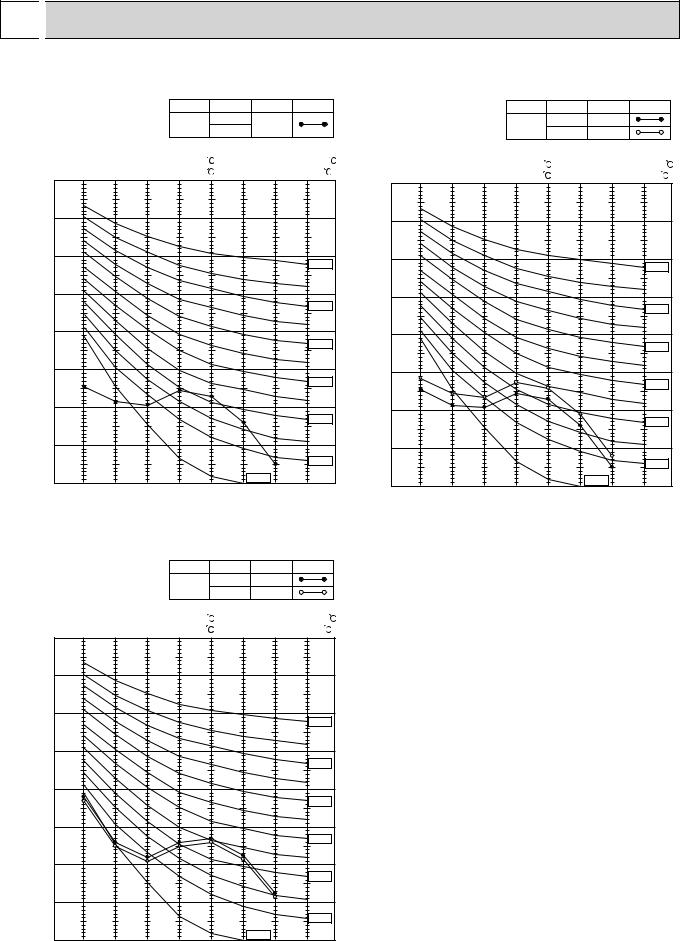
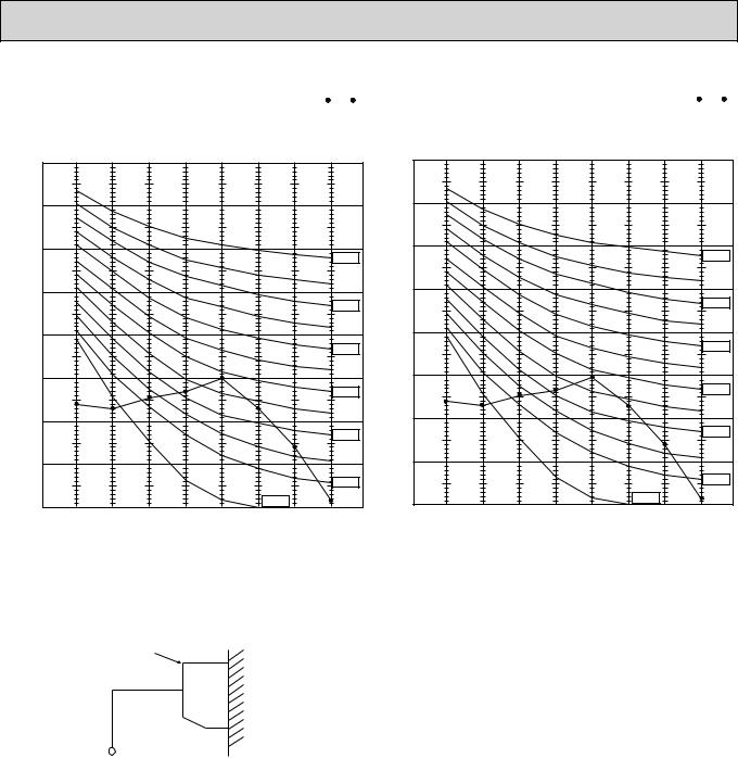
 NOISE CRITERIA CURVES
MSC-GE20VB |
|
FAN SPEED |
FUNCTION |
SPL(dB(A)) |
LINE |
MSC-GE25VB |
|
FAN SPEED |
FUNCTION |
SPL(dB(A)) |
LINE |
||||||||
|
|
|
COOLING |
|
|
|
|
|
COOLING |
36 |
|
||||||||
|
|
|
|
High |
|
36 |
|
|
|
|
|
High |
|
|
|||||
|
|
|
|
|
HEATING |
|
|
|
|
|
|
HEATING |
39 |
|
|||||
|
|
|
|
|
|
|
|
|
|
|
|
|
|
|
|||||
|
Test conditions, |
|
|
|
|
|
|
|
|
|
Test conditions, |
|
|
|
|
|
|
|
|
|
Cooling : Dry-bulb temperature 27 |
Wet-bulb temperature19 |
|
|
|
|
|
|
|
|
|
||||||||
|
|
Cooling : Dry-bulb temperature 27 |
Wet-bulb temperature 19 |
||||||||||||||||
|
Heating : Dry-bulb temperature 20 |
Wet-bulb temperature - |
|
||||||||||||||||
|
|
Heating : Dry-bulb temperature 20 |
Wet-bulb temperature - |
||||||||||||||||
|
90 |
|
|
|
|
|
|
|
|
|
|||||||||
|
|
|
|
|
|
|
|
|
|
90 |
|
|
|
|
|
|
|
|
|
|
|
|
|
|
|
|
|
|
|
|
|
|
|
|
|
|
|
|
|
OCTAVE BAND SOUND PRESSURE LEVEL, dB re 0.0002 MICRO BAR |
80 |
|
|
|
|
|
|
|
|
OCTAVE BAND SOUND PRESSURE LEVEL, dB re 0.0002 MICRO BAR |
80 |
|
|
|
|
|
|
|
|
|
|
|
|
|
|
|
|
|
|
|
|
|
|
|
|
|
|||
70 |
|
|
|
|
|
|
|
NC-70 |
70 |
|
|
|
|
|
|
|
|
||
|
|
|
|
|
|
|
|
|
|
|
|
|
|
|
NC-70 |
||||
|
|
|
|
|
|
|
|
|
|
|
|
|
|
|
|
||||
|
|
|
|
|
|
|
|
|
|
|
|
|
|
|
|
|
|||
60 |
|
|
|
|
|
|
|
|
60 |
|
|
|
|
|
|
|
|
||
|
|
|
|
|
|
|
|
|
|
|
|
|
|
|
|
|
|||
|
|
|
|
|
|
|
|
NC-60 |
|
|
|
|
|
|
|
|
NC-60 |
||
|
|
|
|
|
|
|
|
|
|
|
|
|
|
|
|
|
|||
50 |
|
|
|
|
|
|
|
|
50 |
|
|
|
|
|
|
|
|
||
|
|
|
|
|
|
|
|
|
|
|
|
|
|
|
|
|
|||
|
|
|
|
|
|
|
|
NC-50 |
|
|
|
|
|
|
|
|
NC-50 |
||
|
|
|
|
|
|
|
|
|
|
|
|
|
|
|
|
|
|||
40 |
|
|
|
|
|
|
|
|
40 |
|
|
|
|
|
|
|
|
||
|
|
|
|
|
|
|
|
|
|
|
|
|
|
|
|
|
|||
|
|
|
|
|
|
|
|
NC-40 |
|
|
|
|
|
|
|
|
NC-40 |
||
|
|
|
|
|
|
|
|
|
|
|
|
|
|
|
|
|
|||
30 |
|
|
|
|
|
|
|
|
30 |
|
|
|
|
|
|
|
|
||
|
|
|
|
|
|
|
|
|
|
|
|
|
|
|
|
|
|||
|
|
|
|
|
|
|
|
NC-30 |
|
|
|
|
|
|
|
|
NC-30 |
||
|
|
|
|
|
|
|
|
|
|
|
|
|
|
|
|
|
|||
20 |
|
|
|
|
|
|
|
|
|
|
|
|
|
|
|
|
|
||
|
|
|
|
|
|
|
|
|
|
20 |
|
|
|
|
|
|
|
|
|
|
|
|
|
|
|
|
|
|
|
|
|
|
|
|
|
|
|
|
|
|
|
|
|
|
|
|
|
|
NC-20 |
|
|
|
|
|
|
|
|
|
NC-20 |
|
|
|
|
|
|
|
|
|
|
|
|
|
|
|
|
|
|
|
|
|
10 |
|
|
|
|
|
NC-10 |
|
|
10 |
|
|
|
|
|
NC-10 |
|
||
|
|
|
|
|
|
|
|
|
|
|
|
|
|
|
|
||||
|
63 |
125 |
250 |
500 |
1000 |
2000 |
4000 |
8000 |
|
|
|
|
|
|
|
|
|
||
|
|
63 |
125 |
250 |
500 |
1000 |
2000 |
4000 |
8000 |
||||||||||
|
|
|
|
|
|
|
|
|
|
|
|||||||||
BAND CENTER FREQUENCIES, Hz |
BAND CENTER FREQUENCIES, Hz |
|
MSC-GE35VB |
|
FAN SPEED |
FUNCTION |
SPL(dB(A)) |
LINE |
||||
|
|
|
COOLING |
40 |
|
||||
|
|
|
|
High |
|
|
|||
|
|
|
|
|
HEATING |
39 |
|
||
|
|
|
|
|
|
|
|||
|
Test conditions. |
|
|
|
|
|
|
|
|
|
Cooling : Dry-bulb temperature 27 |
Wet-bulb temperature 19 |
|||||||
|
Heating : Dry-bulb temperature 20 |
Wet-bulb temperature - |
|||||||
|
90 |
|
|
|
|
|
|
|
|
MICRO BAR |
80 |
|
|
|
|
|
|
|
|
70 |
|
|
|
|
|
|
|
|
|
dB re 0.0002 |
|
|
|
|
|
|
|
NC-70 |
|
|
|
|
|
|
|
|
|
||
60 |
|
|
|
|
|
|
|
|
|
LEVEL, |
|
|
|
|
|
|
|
|
NC-60 |
|
|
|
|
|
|
|
|
|
|
PRESSURE |
50 |
|
|
|
|
|
|
|
|
|
|
|
|
|
|
|
|
NC-50 |
|
|
|
|
|
|
|
|
|
|
|
BAND SOUND |
40 |
|
|
|
|
|
|
|
|
|
|
|
|
|
|
|
|
NC-40 |
|
30 |
|
|
|
|
|
|
|
|
|
OCTAVE |
|
|
|
|
|
|
|
|
|
|
|
|
|
|
|
|
|
NC-30 |
|
|
|
|
|
|
|
|
|
|
|
|
20 |
|
|
|
|
|
|
|
|
|
|
|
|
|
|
|
|
|
NC-20 |
|
10 |
|
|
|
|
|
NC-10 |
|
|
|
125 |
250 |
500 |
1000 |
2000 |
4000 |
8000 |
||
|
63 |
||||||||
BAND CENTER FREQUENCIES, Hz
5
MS-GE50VB
|
|
|
|
|
|
MSH-GE50VB |
FAN SPEED |
FUNCTION |
SPL(dB(A)) |
|
LINE |
||
High |
COOLING |
42 |
|
|
|
|
|
|
|
|
|||
|
|
|
|
|
|
|
FAN SPEED |
FUNCTION |
SPL(dB(A)) |
|
LINE |
|
High |
COOLING |
42 |
|
|
|
HEATING |
|
|
|
||
|
|
|
|
|
|
Test conditions,
Cooling : Dry-bulb temperature 27°C Wet-bulb temperature 19°C
BAR |
90 |
|
|
|
|
|
|
|
|
|
|
|
|
|
|
|
|
0.0002 MICRO |
80 |
|
|
|
|
|
|
|
70 |
|
|
|
|
|
|
NC-70 |
|
dB re |
60 |
|
|
|
|
|
|
|
LEVEL, |
|
|
|
|
|
|
|
|
|
|
|
|
|
|
|
NC-60 |
|
50 |
|
|
|
|
|
|
|
|
PRESSURE |
|
|
|
|
|
|
|
|
|
|
|
|
|
|
|
NC-50 |
|
40 |
|
|
|
|
|
|
|
|
|
|
|
|
|
|
|
NC-40 |
|
SOUND |
|
|
|
|
|
|
|
|
30 |
|
|
|
|
|
|
|
|
BAND |
|
|
|
|
|
|
|
NC-30 |
20 |
|
|
|
|
|
|
|
|
OCTAVE |
|
|
|
|
|
|
|
|
|
|
|
|
|
|
|
NC-20 |
|
10 |
|
|
|
|
NC-10 |
|
||
|
|
|
|
|
|
|||
|
125 |
250 |
500 |
1000 |
2000 |
4000 |
8000 |
|
|
63 |
|||||||
BAND CENTER FREQUENCIES, Hz
Test conditions,
Cooling : Dry-bulb temperature 27 Wet-bulb temperature 19
 Heating : Dry-bulb temperature 20
 Wet-bulb temperature -
BAR |
|
|
|
|
|
|
|
|
0.0002 MICRO |
80 |
|
|
|
|
|
|
|
70 |
|
|
|
|
|
|
NC-70 |
|
dB re |
60 |
|
|
|
|
|
|
|
LEVEL, |
|
|
|
|
|
|
|
|
|
|
|
|
|
|
|
NC-60 |
|
50 |
|
|
|
|
|
|
|
|
PRESSURE |
|
|
|
|
|
|
|
|
|
|
|
|
|
|
|
NC-50 |
|
40 |
|
|
|
|
|
|
|
|
|
|
|
|
|
|
|
NC-40 |
|
SOUND |
|
|
|
|
|
|
|
|
30 |
|
|
|
|
|
|
|
|
BAND |
|
|
|
|
|
|
|
NC-30 |
20 |
|
|
|
|
|
|
|
|
OCTAVE |
|
|
|
|
|
|
|
|
|
|
|
|
|
|
|
NC-20 |
|
10 |
|
|
|
|
NC-10 |
|
||
|
125 |
250 |
500 |
1000 |
2000 |
4000 |
8000 |
|
|
63 |
|||||||
BAND CENTER FREQUENCIES, Hz
INDOOR UNIT
WALL
1m
0.8m
MICROPHONE
6

5 
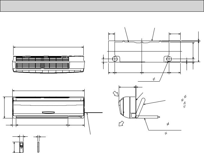
 OUTLINES AND DIMENSIONS
MSC-GE20VB |
81.5 |
|
|
MSC-GE25VB |
|
|
|
Installation plate |
|
|
|
|
|
|
|
|
Indoor unit |
|
|
|
783 |
|
|
|
41 |
|
|
|
81.5 |
326 |
326 |
133.5 |
4.5 |
|
|
|
|
|
231.5 |
271 |
2.5 |
42 |
|
81.5
Wall hole  65
65
Unit: mm
|
815 |
|
Air in |
|
|
|
|
278 |
|
|
or more |
|
|
|
7 |
60 |
606 |
149 |
30 |
|
|
|
|
58 |
19 |
Power supply cord |
Air out |
|
|
|
|
|
|
Lead to right 1.0m |
|
162 |
|
Lead to left 0.3m |
|
|
|
|
242
244
5Installation plate
{Liquid line 6.35-0.5m Gas line 9.52-0.43m Insulation 37 O.D
 21 I.D
90
110Drain hose 16 (Connected part O,D) Insulation  28
28
Wireless remote controller
MSC-GE35VB
161.5
|
Installation plate |
|
|
783 |
Indoor unit |
|
|
|
|
|
|
|
41 |
|
|
|
81.5 |
326 |
326 |
Unit: mm
161.5 |
17.5 |
|
|
|
|
|
218.5 |
258 |
2.5 |
42 |
|
81.5 |
|
|
Wall hole  65
65
|
815 |
|
Air in |
|
|
|
|
278 |
|
|
or more |
|
|
|
7 |
60 |
606 |
149 |
30 |
|
|
|
58 19
162
Wireless remote controller
Air out
Power supply cord Lead to right 1.0m Lead to left 0.3m
7
2425 Installation plate
{Liquid line 6.35-0.5m Gas line 9.52-0.43m Insulation 37 O.D
 21 I.D
90
110Drain hose 16 (Connected part O,D)
244 |
Insulation 28 |
|
MS-GE50VB
MSH-GE50VB
1068
1100
325
56 |
791 |
58 |
19 |
162 |
|
Wireless remote controller
Installation plate |
Indoor unit |
|
|
Unit: mm |
||
|
|
|
|
|||
98 |
|
|
173 |
|
|
7.5 |
|
|
|
|
|
|
|
|
|
|
|
|
255.5 |
315 |
47 |
414.5 |
414.5 |
173 |
2.5 |
47 |
|
98 |
|
|
|
|||
|
|
Wall hole 75 |
|
|
|
|
Air in |
258 |
5 |
|
|
|
|
|
Installation plate |
|
|
|
|
|
|
|
|
|
|
|
|
|
|
|
Liquid line |
6.35- 0.5 m |
||
|
|
|
Gas line 12-0.43 m |
|||
|
|
{Insulation |
50 O.D |
|||
|
|
|
|
|
32 I.D |
|
253 |
|
Drain hose |
16 |
|
|
|
Air out |
|
(Connected part O.D) |
|
|
|
|
|
Insulation |
28 |
|
|
|
|
Power supply cord |
|
|
|
|
||
|
|
|
|
|
|
|
Lead to right 2.0 m |
|
|
|
|
|
|
Lead to left 1.0 m |
|
|
|
|
|
|
8

6 
 WIRING DIAGRAM
MSC-GE20VB MSC-GE25VB MSC-GE35VB
MS-GE50VB
MSH-GE50VB
9
7 
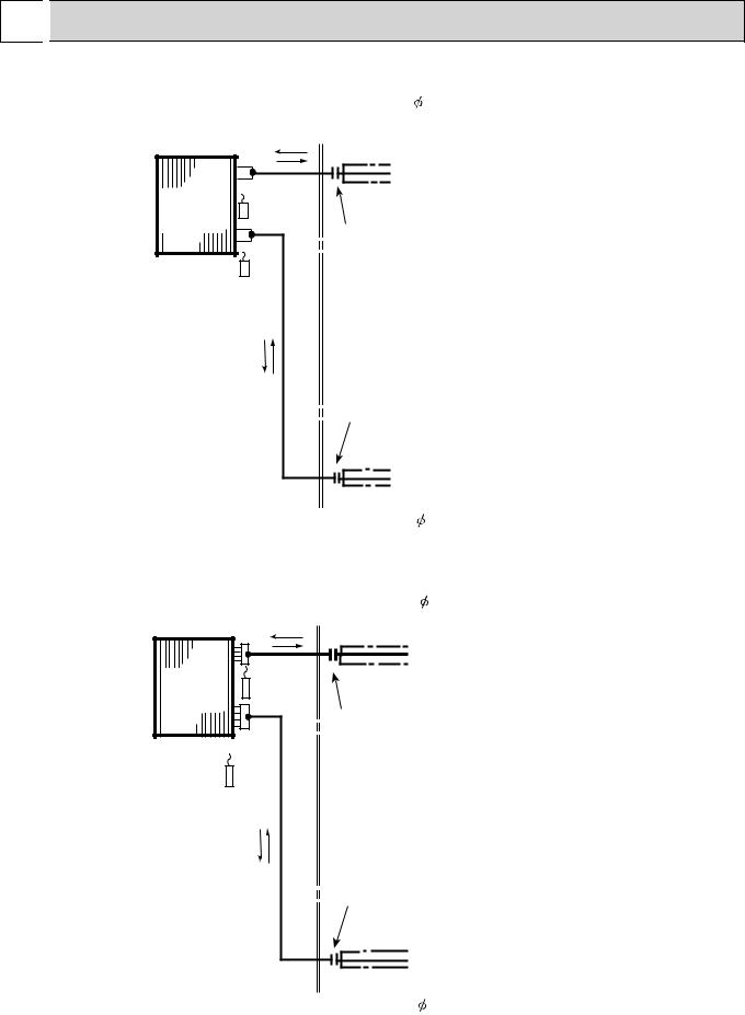
 REFRIGERANT SYSTEM DIAGRAM
MSC-GE20VB MSC-GE25VB MSC-GE35VB
Refrigerant pipe 9.52 |
Unit:mm |
(with heat insulator) |
|
Indoor |
Indoor coil |
|
thermistor |
||
heat |
||
RT12 |
||
exchanger |
||
|
Flared connection |
Room temperature thermistor
RT11
Flared connection
Refrigerant pipe 6.35 (with heat insulator)
MS-GE50VB MSH-GE50VB
Refrigerant pipe 12.7 (with heat insulator)
Indoor |
Indoor coil |
thermistor |
|
heat |
RT12 |
exchanger |
Distributor |
Flared connection
Room temperature thermistor
RT11
Flared connection
Refrigerant pipe 6.35 (with heat insulator)
 Refrigerant flow in cooling
 Refrigerant flow in heating (MSC,MSH)
10
8 
 SERVICE FUNCTIONS
MSC-GE20VB MS-GE50VB
MSC-GE25VB MSH-GE50VB MSC-GE35VB
8-1. TIMER SHORT MODE
For service, set time can be shortened by short circuit of JPG and JPS on the electronic control P.C. board. The time will be shortened as follows.
Set time: 1 minute |
1-second |
Set time: 3 minute |
3-second (It takes 3 minutes for the compressor to start operation. However, the starting time is short- |
|
ened by short circuit of JPG and JPS.) |
8-2. P.C. BOARD MODIFICATION FOR INDIVIDUAL OPERATION
A maximum of 4 indoor units with wireless remote controllers can be used in a room.
In this case, to operate each indoor unit individually by each remote controller, P.C. boards of remote controller must be modified according to the number of the indoor unit.
How to modify the remote controller P.C. board
Remove batteries before modification. The board has a print as shown below:
NOTE: For modification, take out the batteries and press the OPERATE/STOP (ON/OFF) button 2 or 3 times at first. After modification, put back the batteries then press the RESET button.
J1 J2
The P.C. board has the print “J1” and “J2”. Solder “J1” and “J2” according to the number of indoor unit as shown in Table 1. After modification, press the RESET button.
Table 1
|
1 unit operation |
2 units operation |
3 units operation |
4 units operation |
|
|
|
|
|
No. 1 unit |
No modification |
Same as at left |
Same as at left |
Same as at left |
|
|
|
|
|
No. 2 unit |
– |
Solder J1 |
Same as at left |
Same as at left |
|
|
|
|
|
No. 3 unit |
– |
– |
Solder J2 |
Same as at left |
|
|
|
|
|
No. 4 unit |
– |
– |
– |
Solder both J1 and J2 |
|
|
|
|
|
How to set the remote controller exclusively for particular indoor unit
After you turn the breaker ON, the first remote controller that sends the signal to the indoor unit will be regarded as the remote controller for the indoor unit.
The indoor unit only accepts the signal from the remote controller that has been assigned to the indoor unit once they are set. The setting will be cancelled if the breaker has turned off, or the power supply has shut down.
Please conduct the above setting once again after the power has restored.
8-3. REMOTE CONTROLLER (How to set the type) MSC-GE
This remote controller setting needs to be switched according to the type of air conditioner (COOL & HEAT or COOL ONLY).
If the setting is incorrect, the air conditioner does not operate normally. Therefore, check if the setting corresponds to the type of-air conditioner. If not, correct the setting as shown below.
Slide switch |
Type COOL & HEAT COOL ONLY |
|
The position of the slide switch
11
 Loading...