


SPLIT-TYPE, AIR CONDITIONERS
SPLIT-TYPE, HEAT PUMP AIR CONDITIONERS
No. OB385
SERVICE MANUAL
Wireless type Models
MSC-GA20VB MSC-GA25VB MSC-GA35VB
-E1 (WH)
-E1 (WH)
-E1 (WH)
CONTENTS
Indication of model name
MSC-GA20VB - E1 MSC-GA25VB - E1 MSC-GA35VB - E1
1.TECHNICAL CHANGES ················
2.PART NAMES AND FUNCTIONS············
3.SPECIFICATION····················
4.NOISE CRITERIA CURVES ···············
5.OUTLINES AND DIMENSIONS ·············
6.WIRING DIAGRAM ··················
7.REFRIGERANT SYSTEM DIAGRAM ··········
8.SERVICE FUNCTIONS ·················
9.TROUBLESHOOTING·················
10.DISASSEMBLY INSTRUCTIONS············
11.PARTS LIST······················
12.OPTIONAL PARTS··················
NOTE:
•This manual describes technical data of indoor units.
•As for outdoor units MU-GA20/GA25/GA35VB - E1 , refer to the service manual OB386. •As for outdoor units MUH-GA20/GA25/GA35VB - E1 , refer to the service manual OB387.
•As for outdoor units MUX-2A28/2A59/3A60/3A63/2A70/4A73VB - E1 , refer to the service manual OB384.
•As for outdoor units MXZ-A14/A18/A26/A32WV - E1 , refer to the service manual OB319 REVISED EDITION-A.

2
1 TECHNICAL CHANGES
MSC-A07YV - E1 MSC-GA20VB - E1
1.Indication of capacity has been changed. (BTU base kW)
2.P.C. board has been changed.
3.Air cleaning filter has been changed to optional parts.
4.Fan motor has been changed.
5.Fan motor capacitor has been changed.
6.Color of indoor unit has been changed.
MSC-A09YV - E1 MSC-GA25VB - E1
1.Indication of capacity has been changed. (BTU base kW)
2.P.C. board has been changed.
3.Air cleaning filter has been changed to optional parts.
4.Fan motor has been changed.
5.Fan motor capacitor has been changed.
6.Color of indoor unit has been changed.
MSC-A12YV - E1 MSC-GA35VB - E1
1.Indication of capacity has been changed. (BTU base kW)
2.P.C. board has been changed.
3.Air cleaning filter has been changed to optional parts.
4.Fan motor has been changed.
5.Fan motor capacitor has been changed.
6.Color of indoor unit has been changed.
2 
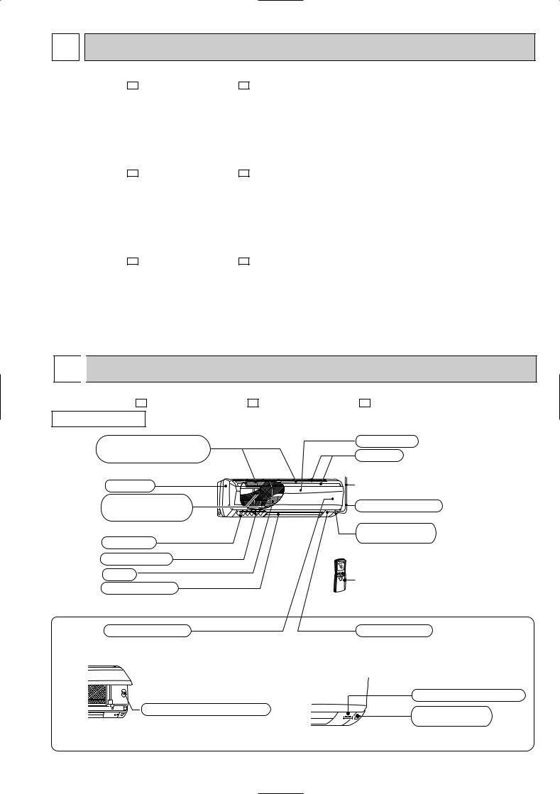
 PART NAMES AND FUNCTIONS
MSC-GA20VB - E1 MSC-GA25VB - E1 MSC-GA35VB - E1
INDOOR UNIT
Air cleaning filter(option) |
Front panel |
|
(white bellows type) |
Air inlet |
|
Panel |
to Breaker |
|
Catechin air filter |
Power supply cord |
|
(With deodorizer) |
||
|
||
|
Remote control |
|
Air outlet |
receiving section |
|
|
||
Vertical vanes |
|
|
Fan |
Remote controller |
|
Horizontal vane |
||
|
||
Operation section |
Display section |
|
(When the front panel is opened) |
|
|
Operation indicator lamp |
Emergency operation switch |
Remote control |
|
receiving section |
3
MSC-GA20VB - E1
MSC-GA25VB - E1
MSC-GA35VB - E1
ACCESSORIES
<Indoor unit>
1 |
Installation plate |
1 |
|
|
|
2 |
Installation plate fixing screw 4 o 25 mm |
5 |
|
|
|
3 |
Remote controller holder |
1 |
|
|
|
4 |
Fixing screw for 3 3.5 o 16 mm |
2 |
|
|
|
5 |
Battery (AAA) for remote controller |
2 |
|
|
|
6 |
Wireless remote controller |
1 |
|
|
|
7 |
Felt tape (Used for left or left-rear piping) |
1 |
|
|
|
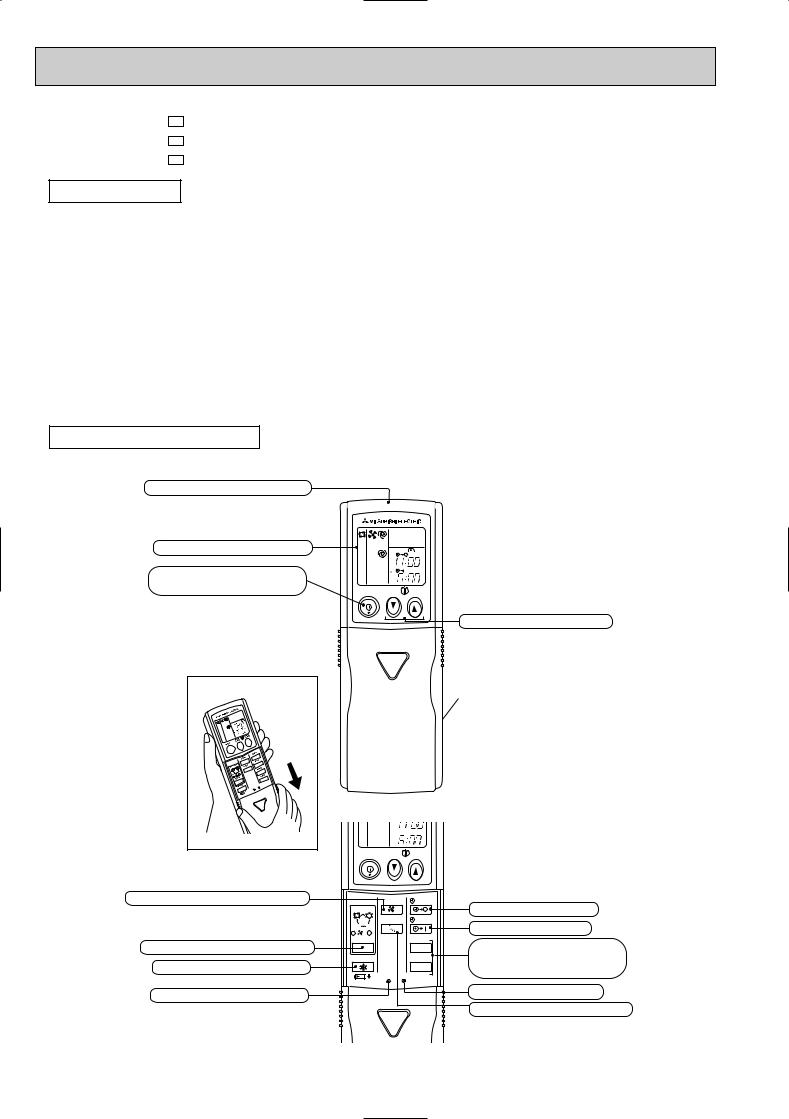
REMOTE CONTROLLER
Signal transmitting section
Operation display section |
|
|
PM |
OPERATE /STOP |
|
|
AM |
|
|
|
|
(ON /OFF) button |
ON/OFF |
TOO |
TOO |
|
|
WARM |
COOL |
Open the front lid. |


 AM
AM
ON/OFF |
TOO |
TOO |
|
WARM |
COOL |
FAN SPEED CONTROL button |
FAN |
STOP |
|
|
I FEEL COOL |
|
|
|
VANE |
START |
|
|
HEAT DRY |
|
|
|
/FAN |
|
|
|
/ |
HR. |
|
OPERATION SELECT button |
MODE |
||
ECONO COOL |
MIN. |
||
ECONO COOL button |
|||
RESET CLOCK |
|
||
|
|
||
RESET button |
|
|
TEMPERATURE buttons
Indication of remote controller model is on back.
OFF-TIMER button ON-TIMER button
HR. button MIN. button (TIME SET button)
CLOCK SET button
VANE CONTROL button
4

3 SPECIFICATION
Indoor model
Function
Indoor unit power supply
Capacity Air flow(High/Med.w/Loww)
Electrical |
data |
Power outlet |
|
Running current |
|||
|
|
||
|
|
Power input |
|
|
|
Power factor |
|
|
|
Fan motor current |
|
Fan |
motor |
Model |
|
Winding |
|||
|
|
||
|
|
resistance(at 20:) |
|
|
|
Dimensions WOHOD |
|
|
|
Weight |
|
|
|
Air direction |
|
|
remarks |
Sound level(High/Med.w/Loww) |
|
Special |
Fan speed(High/Med.w/Loww) |
||
Thermistor RT11(at 25:) |
|||
|
|
Fan speed regulator |
|
|
|
Thermistor RT12(at 25:) |
|
|
|
Remote controller model |
|
MSC-GA20VB - E1 |
MSC-GA25VB - E1 |
MSC-GA35VB - E1 |
||||||||
|
Cooling |
|
Heating |
Cooling |
|
Heating |
Cooling |
|
Heating |
||
|
Single phase |
Single phase |
Single phase |
||||||||
|
230V,50Hz |
230V,50Hz |
230V,50Hz |
||||||||
K /h |
474/372w/276w |
510/420w/342w |
474/384 w/306w |
588/456w/342w |
582/444w/324w |
606/498w/396w |
|||||
A |
|
10 |
10 |
|
|
10 |
|||||
A |
0.17 |
0.17 |
|
0.19 |
|||||||
W |
|
35 |
35 |
|
|
40 |
|||||
% |
|
90 |
90 |
|
|
92 |
|||||
A |
0.17 |
0.17 |
|
0.19 |
|||||||
|
RC4V19-JA |
RC4V19-JA |
RC4V19-HA |
||||||||
" |
WHT-BLK 283 |
WHT-BLK 283 |
WHT-BLK 224 |
||||||||
BLK-RED 188 |
BLK-RED 188 |
BLK-RED 318 |
|||||||||
|
|||||||||||
mm |
815O278O244 |
815O278O244 |
815O278O244 |
||||||||
kg |
|
9 |
9 |
|
|
10 |
|||||
|
|
5 |
5 |
|
|
5 |
|||||
dB |
36/31w/25 w |
|
36/31w/25 w |
36/31w/25w |
|
|
39/32w/25 w |
40/33w/26w |
|
39/33w/26w |
|
rpm |
900/750w/600w |
950/820w/700w |
900/770w/650w |
|
1,050/870w/700w |
930/760w/600w |
960/830w/700w |
||||
|
|
3 |
3 |
|
|
3 |
|||||
k" |
|
10 |
10 |
|
|
10 |
|||||
k" |
|
10 |
10 |
|
|
10 |
|||||
|
KP1A |
KP1A |
KP1A |
||||||||
NOTE: 1. Test conditions are based on ISO 5151. |
|
|
|
Cooling : Indoor |
DB27°C WB19°C |
Heating : Indoor |
DB20°C |
Outdoor |
DB35°C WB24°C |
Outdoor |
DB7°C WB6°C |
Indoor-Outdoor piping length 5m
W Reference value
5

4 NOISE CRITERIA CURVES
MSC-GA20VB- |
E1 |
FAN SPEED FUNCTION |
SPL(dB(A)) |
LINE |
|||||
|
|
|
|
|
|||||
|
|
|
|
|
High |
COOLING |
36 |
|
|
|
|
|
|
|
HEATING |
|
|||
|
|
|
|
|
|
|
|
||
|
|
|
|
|
Test conditions, |
|
|
||
|
|
|
|
|
|
Cooling : DB27: |
WB19: |
||
|
90 |
|
|
|
|
Heating : DB20: |
WB -: |
||
|
|
|
|
|
|
|
|
|
|
MICRO BAR |
80 |
|
|
|
|
|
|
|
|
70 |
|
|
|
|
|
|
|
|
|
dB re 0.0002 |
|
|
|
|
|
|
|
|
|
|
|
|
|
|
|
|
|
NC-70 |
|
60 |
|
|
|
|
|
|
|
|
|
LEVEL, |
|
|
|
|
|
|
|
|
NC-60 |
|
|
|
|
|
|
|
|
|
|
PRESSURE |
50 |
|
|
|
|
|
|
|
|
|
|
|
|
|
|
|
|
NC-50 |
|
|
|
|
|
|
|
|
|
|
|
BAND SOUND |
40 |
|
|
|
|
|
|
|
|
|
|
|
|
|
|
|
|
NC-40 |
|
30 |
|
|
|
|
|
|
|
|
|
OCTAVE |
|
|
|
|
|
|
|
|
|
|
|
|
|
|
|
|
|
NC-30 |
|
|
|
|
|
|
|
|
|
|
|
|
20 |
APPROXIMATE |
|
|
|
|
|
|
|
|
|
TERESHOLD OF |
|
|
|
|
|
|
|
|
|
HEARING FOR |
|
|
|
|
|
NC-20 |
|
|
|
CONTINUOUS |
|
|
|
|
|
||
|
|
|
|
|
|
|
|
||
|
|
NOISE |
|
|
|
|
|
|
|
|
10 |
63 |
125 |
250 |
500 |
1000 |
2000 |
4000 |
8000 |
|
|
||||||||
BAND CENTER FREQUENCIES, Hz
MSC-GA35VB- |
E1 |
FAN SPEED FUNCTION |
SPL(dB(A)) |
LINE |
|||||
|
|
|
|
|
|||||
|
|
|
|
|
High |
COOLING |
40 |
|
|
|
|
|
|
|
HEATING |
39 |
|
||
|
|
|
|
|
|
|
|||
|
|
|
|
|
Test conditions. |
|
|
||
|
|
|
|
|
|
Cooling : DB27: |
WB19: |
||
|
90 |
|
|
|
|
Heating : DB20: |
WB -: |
||
|
|
|
|
|
|
|
|
|
|
MICRO BAR |
80 |
|
|
|
|
|
|
|
|
70 |
|
|
|
|
|
|
|
|
|
dB re 0.0002 |
|
|
|
|
|
|
|
|
|
|
|
|
|
|
|
|
|
NC-70 |
|
60 |
|
|
|
|
|
|
|
|
|
LEVEL, |
|
|
|
|
|
|
|
|
NC-60 |
|
|
|
|
|
|
|
|
|
|
PRESSURE |
50 |
|
|
|
|
|
|
|
|
|
|
|
|
|
|
|
|
NC-50 |
|
|
|
|
|
|
|
|
|
|
|
BAND SOUND |
40 |
|
|
|
|
|
|
|
|
|
|
|
|
|
|
|
|
NC-40 |
|
30 |
|
|
|
|
|
|
|
|
|
OCTAVE |
|
|
|
|
|
|
|
|
|
|
|
|
|
|
|
|
|
NC-30 |
|
|
|
|
|
|
|
|
|
|
|
|
20 |
APPROXIMATE |
|
|
|
|
|
|
|
|
|
TERESHOLD OF |
|
|
|
|
|
|
|
|
|
HEARING FOR |
|
|
|
|
|
NC-20 |
|
|
|
CONTINUOUS |
|
|
|
|
|
||
|
|
|
|
|
|
|
|
||
|
|
NOISE |
|
|
|
|
|
|
|
|
10 |
63 |
125 |
250 |
500 |
1000 |
2000 |
4000 |
8000 |
|
|
||||||||
BAND CENTER FREQUENCIES, Hz
MSC-GA25VB- |
E1 |
FAN SPEED FUNCTION |
SPL(dB(A)) |
LINE |
|||||
|
COOLING |
36 |
|
||||||
|
|
|
|
|
High |
HEATING |
39 |
|
|
|
|
|
|
|
|
|
|||
|
|
|
|
|
Test conditions. |
|
|
||
|
|
|
|
|
|
Cooling : DB27: |
WB19: |
||
|
90 |
|
|
|
|
Heating : DB20: |
WB -: |
||
|
|
|
|
|
|
|
|
|
|
MICRO BAR |
80 |
|
|
|
|
|
|
|
|
70 |
|
|
|
|
|
|
|
|
|
dB re 0.0002 |
|
|
|
|
|
|
|
|
|
|
|
|
|
|
|
|
|
NC-70 |
|
60 |
|
|
|
|
|
|
|
|
|
LEVEL, |
|
|
|
|
|
|
|
|
NC-60 |
|
|
|
|
|
|
|
|
|
|
PRESSURE |
50 |
|
|
|
|
|
|
|
|
|
|
|
|
|
|
|
|
NC-50 |
|
|
|
|
|
|
|
|
|
|
|
BAND SOUND |
40 |
|
|
|
|
|
|
|
|
|
|
|
|
|
|
|
|
NC-40 |
|
30 |
|
|
|
|
|
|
|
|
|
OCTAVE |
|
|
|
|
|
|
|
|
|
|
|
|
|
|
|
|
|
NC-30 |
|
|
|
|
|
|
|
|
|
|
|
|
20 |
APPROXIMATE |
|
|
|
|
|
|
|
|
|
TERESHOLD OF |
|
|
|
|
|
|
|
|
|
HEARING FOR |
|
|
|
|
|
NC-20 |
|
|
|
CONTINUOUS |
|
|
|
|
|
||
|
|
|
|
|
|
|
|
||
|
|
NOISE |
|
|
|
|
|
|
|
|
10 |
63 |
125 |
250 |
500 |
1000 |
2000 |
4000 |
8000 |
|
|
||||||||
BAND CENTER FREQUENCIES, Hz
INDOORUNIT
WALL
1m
0.8m
MICROPHONE
6

5 
 OUTLINES AND DIMENSIONS
MSC-GA20VB - E1 |
81.5 |
|
|
|
|
Unit: mm |
MSC-GA25VB - E1 |
|
|
133.5 |
4.5 |
||
INDOOR UNIT |
Installation plate |
|
|
|
|
|
|
|
|
231.5 |
271 |
||
|
Indoor unit |
|
|
|
||
|
|
|
|
|
|
|
|
783 |
|
|
|
|
|
|
41 |
|
|
2.5 |
42 |
|
|
81.5 |
326 |
326 |
81.5 |
|
|
|
|
|
|
Wall hole [65 |
||
|
815 |
|
278 |
|
|
60 |
606 |
149 |
58 |
|
19 |
|
Power supply cord |
|
Lead to right 1.0m |
162 |
Lead to left 0.3m |
|
Air in |
242 |
5 |
Installation plate |
|
|
||||
more |
|
|
{ |
Liquid line [6.35-0.5m |
|
|
Gas line [9.52-0.43m |
||
7 or |
|
|
Insulation [37 O.D |
|
|
|
|
[21 I.D |
|
30 |
|
90 |
|
Drain hose [16 |
|
110 |
|||
|
|
(Connected part O,D) |
||
|
|
|
|
|
Air out |
244 |
|
|
Insulation [28 |
|
|
|
|
|
Wireless remote controller |
|
|
|
|
|
|
MSC-GA35VB - E1 |
161.5 |
|
|
161.5 |
|
17.5 |
INDOOR UNIT |
Installation plate |
|
|
|
|
|
|
|
|
|
|
||
|
|
|
|
|
|
|
|
Indoor unit |
|
|
|
218.5 |
258 |
|
|
|
|
|
|
|
|
783 |
|
|
|
|
|
|
41 |
|
|
2.5 |
42 |
|
|
81.5 |
326 |
326 |
81.5 |
|
|
|
|
|
|
Wall hole [65 |
||
|
815 |
|
278 |
|
|
60 |
606 |
149 |
58 |
|
19 |
|
Power supply cord |
|
Lead to right 1.0m |
162 |
Lead to left 0.3m |
|
Air in |
242 |
5 |
Installation plate |
|
|
||||
more |
|
|
|
Liquid line [6.35-0.5m |
|
|
|
Gas line [9.52-0.43m |
|
|
|
{ Insulation [37 O.D |
||
or |
|
|
||
|
|
|
[21 I.D |
|
7 |
|
|
|
|
|
|
|
|
|
30 |
|
90 |
|
Drain hose [16 |
|
110 |
|||
|
|
(Connected part O,D) |
||
|
|
|
|
|
Air out |
244 |
|
|
Insulation [28 |
|
|
|
|
|
Wireless remote controller
7
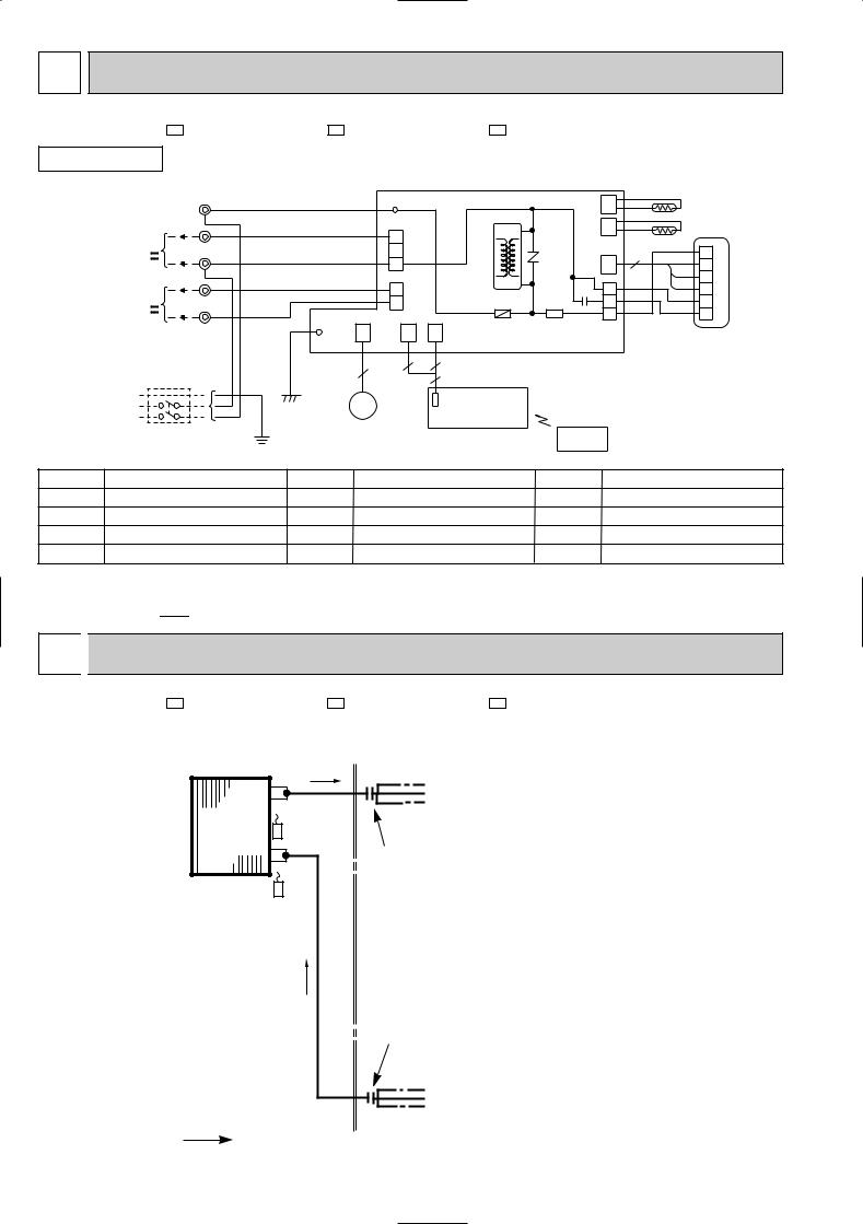
6 |
WIRING DIAGRAM |
|
|
|
|
|
|
|
|
|||
MSC-GA20VB - E1 |
MSC-GA25VB - E1 |
MSC-GA35VB - E1 |
|
|
|
|
|
|||||
INDOOR UNIT |
|
|
MODELS WIRING DIAGRAM |
|
|
|
|
|
||||
|
TO OUTDOOR |
TB |
|
|
|
|
|
|
|
|
|
|
|
UNIT |
|
|
|
LD105 |
|
|
CN |
|
|
|
|
|
L |
BRN |
|
|
|
|
|
RT12 |
||||
|
CONNECTING |
|
|
|
|
|
||||||
|
BRN |
|
|
|
|
|
|
112 |
|
|
|
|
|
|
|
|
|
CN201 |
|
|
CN |
|
RT11 |
||
|
FOR MUH OR |
3 |
RED |
|
|
T11 |
|
|
||||
|
|
|
3 |
|
111 |
|
||||||
|
MXZ-A TYPE |
|
|
|
|
|
|
|
|
BLK |
|
|
|
N |
|
|
|
2 |
|
|
|
|
1 |
||
|
12V |
BLU |
|
|
|
NR11 |
|
3 |
||||
|
|
|
|
CN |
GRY |
|||||||
|
|
|
1 |
|
2 |
|||||||
|
FOR |
BLU |
|
|
|
|
|
121 |
|
YLW |
||
|
|
|
|
CN202 |
|
|
|
3 |
||||
|
|
|
|
|
|
|
|
|||||
|
MU OR |
2 |
WHT |
|
|
2 |
|
C11 |
1 |
|
BRN |
4 MF |
|
|
|
|
|
|
|||||||
|
MUX TYPE |
|
|
|
|
1 |
F11 |
SR141 |
3 |
|
WHT |
5 |
|
12V |
1 |
BLK |
|
|
|
|
|
5 |
|
RED |
6 |
|
POWER |
|
LD103 |
CN |
CN |
CN |
CN211 |
|
|
|
||
|
|
|
151 |
109 |
125 |
|
|
|
|
|
||
|
SUPPLY |
|
|
|
|
ELECTRONIC CONTROL P.C. BOARD |
|
|
|
|||
|
CORD |
|
|
|
3 |
2 |
|
|
|
|
|
|
|
~/N 230V |
|
|
5 |
|
|
|
|
|
|||
|
50Hz |
|
GRN |
|
|
5 |
|
|
|
|
|
|
|
|
|
|
|
|
|
|
|
|
|||
|
PE |
|
|
|
|
|
|
|
|
|
|
|
|
|
GRN/YLW |
MV |
|
POWER MONITOR |
|
|
|
|
|
||
|
|
|
|
|
|
|
|
|
||||
|
|
|
|
RECEIVER P.C.BOARD |
|
|
|
|
|
|||
|
|
|
|
|
|
|
|
|
|
|
||
|
CIRCUIT BREAKER |
|
|
|
|
REMOTE |
|
|
|
|
||
|
|
|
|
|
|
|
|
|
|
|
||
|
|
|
|
|
|
|
|
|
|
|
|
|
|
|
|
|
|
|
|
|
CONTROLLER |
|
|
|
|
SYMBOL |
NAME |
|
SYMBOL |
|
|
NAME |
SYMBOL |
|
|
NAME |
||
C11 |
INDOOR FAN CAPACITOR |
NR11 |
VARISTOR |
|
TB |
TERMINAL BLOCK |
||||||
F11 |
FUSE(3.15A) |
|
RT11 |
ROOM TEMPERATURE THERMISTOR |
T11 |
TRANSFORMER |
||||||
MF |
INDOOR FAN MOTOR (INNER FUSE) |
RT12 |
INDOOR COIL THERMISTOR |
MV |
VANE MOTOR |
SR141 |
SOLID STATE RELAY |
NOTE:1. About the outdoor side electric wiring refer to the outdoor unit electric wiring diagram for servicing.
2.Use copper conductors only. (For field wiring)
3.Symbols below indicate.
/: Terminal block,  : Connector
7 
 REFRIGERANT SYSTEM DIAGRAM
MSC-GA20VB - E1 |
MSC-GA25VB - E1 MSC-GA35VB - E1 |
|
Refrigerant pipe [9.52 Unit:mm |
INDOOR UNIT |
|
|
(with heat insulator) |
|
Indoor |
Indoor coil |
|
thermistor |
||
heat |
||
RT12 |
||
exchanger |
||
Flared connection |
||
|
Room temperature thermistor
RT11
Flared connection
Refrigerant flow |
Refrigerant pipe [6.35 |
in cooling |
(with heat insulator) |
|
8 |
 Loading...