


MC1000 Series
Installation and Operation Manual

NOTE!
The manual covers software version M108314 and above.
Refer to parameter 63 for the software version of the drive you are working with.
If you are working with an earlier software release, you will not have all of the functionality described in this manual. However, the full functionality of the drive is documented in this manual.
If you are working with M108313 or earlier, parameters 69 and 70 are described in this manual as parameters 98 and 99.
Table of Contents
1 |
GENERAL . . . . . . . . . . . . . . . . . . . . . . . . . . . . . . . . . . . . . |
1 |
|
|
1.1 |
PRODUCTS COVERED IN THIS MANUAL . . . . . . . . . . . . . . . . . . . |
. 1 |
|
1.2 |
PRODUCT CHANGES . . . . . . . . . . . . . . . . . . . . . . . . . . . . |
. 1 |
|
1.3 |
WARRANTY . . . . . . . . . . . . . . . . . . . . . . . . . . . . . . . . . |
1 |
|
1.4 |
RECEIVING . . . . . . . . . . . . . . . . . . . . . . . . . . . . . . . . . . |
1 |
|
1.5 |
CUSTOMER MODIFICATION . . . . . . . . . . . . . . . . . . . . . . . . . |
1 |
2 |
MC1000 SPECIFICATIONS . . . . . . . . . . . . . . . . . . . . . . . . . . . . . . |
2 |
|
3 |
MC1000 MODEL DESIGNATION CODE . . . . . . . . . . . . . . . . . . . . . . . . |
3 |
|
4 |
MC1000 DIMENSIONS . . . . . . . . . . . . . . . . . . . . . . . . . . . . . . . |
4 |
|
|
4.1 |
TYPE 1 DIMENSIONS: MODELS RATED UP TO 30 HP . . . . . . . . . . . . . . |
4 |
|
4.2 |
TYPE 1 DIMENSIONS: MODELS RATED ABOVE 30 HP . . . . . . . . . . . . . . |
6 |
|
4.3 |
TYPE 4, 4X & 12 DIMENSIONS: MODELS RATED UP TO 30HP . . . . . . . . . . |
7 |
|
4.4 |
TYPE 12 DIMENSIONS: MODELS RATED ABOVE 30 HP . . . . . . . . . . . . . . . . . . . . . . . . . . |
9 |
5 |
MC1000 RATINGS . . . . . . . . . . . . . . . . . . . . . . . . . . . . . . . . . |
10 |
|
6 |
THEORY . . . . . . . . . . . . . . . . . . . . . . . . . . . . . . . . . . . . . |
14 |
|
|
6.1 |
DESCRIPTION OF AC MOTOR OPERATION . . . . . . . . . . . . . . . . . . |
14 |
|
6.2 |
DRIVE FUNCTION DESCRIPTION . . . . . . . . . . . . . . . . . . . . . . . |
16 |
7 |
INSTALLATION . . . . . . . . . . . . . . . . . . . . . . . . . . . . . . . . . . |
17 |
|
|
7.1 |
INSTALLATION AFTER A LONG PERIOD OF STORAGE . . . . . . . . . . . . . |
18 |
|
7.2 |
EXPLOSION PROOF APPLICATIONS . . . . . . . . . . . . . . . . . . . . . |
18 |
8 |
INPUT AC REQUIREMENTS . . . . . . . . . . . . . . . . . . . . . . . . . . . . . |
19 |
|
|
8.1 |
INPUT AC POWER REQUIREMENTS . . . . . . . . . . . . . . . . . . . . . . |
19 |
|
8.2 |
INPUT FUSING AND DISCONNECT REQUIREMENTS . . . . . . . . . . . . . . |
19 |
9 |
VOLTAGE SELECTION . . . . . . . . . . . . . . . . . . . . . . . . . . . . . . . |
20 |
|
10 |
POWER WIRING . . . . . . . . . . . . . . . . . . . . . . . . . . . . . . . . . . |
21 |
|
|
10.1 |
WIRING FOR SINGLE PHASE OR THREE PHASE INPUT . . . . . . . . . . . . . |
21 |
11 |
MC1000 POWER WIRING DIAGRAM . . . . . . . . . . . . . . . . . . . . . . . . |
22 |
|
12 |
INITIAL POWER UP . . . . . . . . . . . . . . . . . . . . . . . . . . . . . . . . |
23 |
|
13 |
KEYPAD CONTROL . . . . . . . . . . . . . . . . . . . . . . . . . . . . . . . . |
24 |
|
|
13.1 |
KEYPAD FUNCTIONS (IN LOCAL MODE) . . . . . . . . . . . . . . . . . . . |
24 |
|
13.2 |
MC1000 DISPLAY . . . . . . . . . . . . . . . . . . . . . . . . . . . . . . |
25 |
14 |
CONTROL WIRING . . . . . . . . . . . . . . . . . . . . . . . . . . . . . . . . . |
29 |
|
|
14.1 |
GENERAL . . . . . . . . . . . . . . . . . . . . . . . . . . . . . . . . . . |
29 |
|
14.2 |
START/STOP AND SPEED CONTROL . . . . . . . . . . . . . . . . . . . . . |
29 |
15 |
MC1000 CONTROL WIRING DIAGRAMS . . . . . . . . . . . . . . . . . . . . . . |
34 |
|
|
15.1 |
MC1000 TERMINAL STRIP . . . . . . . . . . . . . . . . . . . . . . . . . . |
34 |
|
15.2 |
TWO-WIRE START/STOP CONTROL . . . . . . . . . . . . . . . . . . . . . . |
35 |
|
15.3 |
THREE-WIRE START/STOP CONTROL . . . . . . . . . . . . . . . . . . . . . |
36 |
|
15.4 |
SPEED POT AND PRESET SPEED CONTROL . . . . . . . . . . . . . . . . . . |
37 |
16 |
PROGRAMMING THE MC1000 DRIVE . . . . . . . . . . . . . . . . . . . . . . . . |
38 |
|
|
16.1 |
PROGRAMMING THE PARAMETERS . . . . . . . . . . . . . . . . . . . . . |
38 |
|
16.2 |
PARAMETER ACCESS USING SPEED DIAL . . . . . . . . . . . . . . . . . . . |
40 |
17 |
PARAMETER MENU . . . . . . . . . . . . . . . . . . . . . . . . . . . . . . . . |
41 |
|
18 |
DESCRIPTION OF PARAMETERS . . . . . . . . . . . . . . . . . . . . . . . . . . |
44 |
|
19 |
MC1000 PID SET POINT CONTROL . . . . . . . . . . . . . . . . . . . . . . . . . |
70 |
|
|
19.1 |
FEEDBACK DEVICES . . . . . . . . . . . . . . . . . . . . . . . . . . . . . |
70 |
|
19.2 |
THE SYSTEM - DIRECT AND REVERSE ACTING . . . . . . . . . . . . . . . . |
71 |
|
19.3 |
PID CONTROL - DIRECT AND REVERSE ACTING . . . . . . . . . . . . . . . . |
71 |
|
19.4 |
SET POINT REFERENCE SOURCES . . . . . . . . . . . . . . . . . . . . . . |
72 |
|
19.5 |
TUNING THE PID CONTROL . . . . . . . . . . . . . . . . . . . . . . . . . |
72 |
|
19.6 |
MC1000 DISPLAY IN PID MODE . . . . . . . . . . . . . . . . . . . . . . . |
73 |
20 |
TROUBLESHOOTING . . . . . . . . . . . . . . . . . . . . . . . . . . . . . . . |
74 |
|
21 |
USER SETTING RECORD . . . . . . . . . . . . . . . . . . . . . . . . . . . . . . |
76 |
|
APPENDIX . |
. . . . . . . . . . . . . . . . . . . . . . . . . . . . . . . . . . . . . . |
78 |
|
A |
SINGLE PHASE DATA SELECTED MODELS . . . . . . . . . . . . . . . . . . . . . . |
78 |
|
|
A-1 |
WIRING . . . . . . . . . . . . . . . . . . . . . . . . . . . . . . . . . . . |
78 |
|
A-2 |
DERATING . . . . . . . . . . . . . . . . . . . . . . . . . . . . . . . . . |
78 |

13435742_EDBM101_v24 |
1 |

2 |
MC1000 SPECIFICATIONS |
|
|
Storage Temperature |
-20° to 70° C |
|
|
Ambient Operating Temperature |
Chassis (w/o cover) |
-10° to 55° C |
|
|
(With 2.5, 6, and 8 kHz carrier, |
Type 1 (IP 31) |
-10° to 50° C |
|
derate for higher carriers) |
Type 4 (IP 65) |
-10° to 40° C |
|
|
Type 12 (IP 54) |
-10° to 40° C |
Ambient Humidity |
Less than 95% (non-condensing) |
||
Altitude |
3300 feet (1000 m) above sea level |
||
|
|
without derating |
|
Input Line Voltages |
240/120 Vac, 240/200 Vac, |
||
|
|
480/400 Vac, and 590/480 Vac |
|
Input Voltage Tolerance |
+10%, -15% |
|
|
Input Frequency Tolerance |
48 to 62 Hz |
|
|
Output Wave Form |
Sine Coded PWM |
|
|
Output Frequency |
0-120 Hz, Optional up to 1000 Hz |
||
Carrier Frequency |
2.5 kHz to 14 kHz |
|
|
Frequency Stability |
+0.00006% / °C |
|
|
Service Factor |
1.00 |
|
|
Efficiency |
> 97% throughout speed range |
||
Power Factor (displacement) |
> 0.96 |
|
|
Overload Current Capacity |
150% of output rating for 60 seconds |
||
|
|
180% of output rating for 30 seconds |
|
Speed Reference Follower |
0-10 VDC, 4-20 mA |
|
|
Control Voltage |
15 VDC |
|
|
Analog Outputs |
0 - 10 VDC, or 2 - 10 VDC |
|
|
|
|
Proportional to speed and load |
|
Digital Outputs |
Form C relay: 2 A at 28 VDC or 120 Vac |
||
|
|
Open-collector outputs: 40 mA at 30 VDC |
|
2 |
13435742_EDBM101_v24 |

3 MC1000 MODEL DESIGNATION CODE
The model number of an MC1000 Series drive gives a full description of the basic drive unit (see example below).
EXAMPLE: M1450BP
(MC1000, 480 Vac, 5 HP, Type 1 Enclosure, with a Remote Keypad Assembly)
M1 4 50 |
B |
P |
Series:
M1 = M1000 Series Variable Speed AC Motor Drive
Input Voltage:
1= 240/120 Vac (For 110, 115, 120, 230 and 240 Vac; 50 or 60 Hz)
2= 240/200 Vac (For 208, 230, and 240 Vac; 50 or 60 Hz)
4= 480/400 Vac (For 380, 415, 440, 460 and 480 Vac; 50 or 60 Hz)
5= 590/480 Vac (For 440, 460, 480, 575 and 600 Vac; 50 or 60 Hz)
Rating:
03 |
= ¼ HP (0.18 kW) |
75 |
= |
7½ HP (5.5 kW) |
500 |
= 50 HP (37.5 kW) |
05 |
= ½ HP (0.37 kW) |
100 |
= |
10 HP (7.5 kW) |
600 |
= 60 HP (45 kW) |
10 |
= 1 HP (0.75 kW) |
150 |
= |
15 HP (11 kW) |
750 |
= 75 HP (55 kW) |
15 |
= 1½ HP (1.1 kW) |
200 |
= |
20 HP (15 kW) |
1000 |
100 HP (75 kW) |
20 |
= 2 HP (1.5 kW) |
250 |
= |
25 HP (18.5 kW) |
1250 |
= 125 HP (90 kW) |
30 |
= 3 HP (2.2 kW) |
300 |
= |
30 HP (22 kW) |
1500 |
= 150 HP (110 kW) |
50 / 51 |
= 5 HP (3.7 kW) |
400 |
= |
40 HP (30vkW) |
|
|
Input Phase:
S= Single phase input only.
No character indicates three phase input only
Enclosure Type:
B= NEMA 1 - General Purpose, vented
C= NEMA 4 - Water-tight and Dust-tight
D= NEMA 12 - Oil-tight and Dust-tight
E= NEMA 4X - Water-tight, Dust-tight, and Corrosion Resistant (Stainless Steel) Standard Options:
H= Additional Form C Relay circuit board
J= Dynamic Braking circuit board
K= Dynamic Braking & Additional Form C Relay board (not available on all HP sizes - consult factory) No character when this type of option is not specified
Interface Options:
P= Remote keypad assembly
No character when this type of option is not specified
13435742_EDBM101_v24 |
3 |
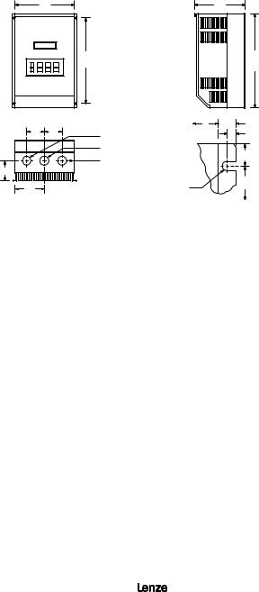
4 MC1000 DIMENSIONS
4.1TYPE 1 DIMENSIONS: MODELS RATED UP TO 30 HP
AT 240/200 Vac AND 60 HP AT 590/480/400 Vac
|
W |
|
|
D |
|
|
|
|
R |
|
H |
|
|
|
|
Conduit Holes: |
W |
U |
IF W < 7.86" |
|
Q |
Q |
T = 0.20" |
||||
S Dia. |
|
V |
||||
|
|
|
U = 0.34" |
|||
|
|
0.88" Dia. |
|
|
||
|
|
|
1.00" |
V = 0.19" |
||
|
|
S Dia. |
|
IF W = 10.26" |
||
|
|
|
|
|||
P |
|
|
|
|
||
|
|
|
|
T = 0.28" |
||
|
|
|
|
R |
||
N |
|
|
T |
U = 0.44" |
||
|
|
|
||||
|
|
|
V = 0.24" |
|||
|
|
|
Dia. Slot |
|
||
|
|
|
Mounting Tab Detail |
|
||
HP |
INPUT |
MODEL |
H |
W |
D |
N |
P |
Q |
R |
S |
|
(kW) |
VOLTAGE |
||||||||||
|
|
|
|
|
|
|
|
|
|||
|
|
|
|
|
|
|
|
|
|
|
|
0.25 |
240 / 120 |
M1103SB |
7.50 |
4.70 |
3.33 |
2.35 |
1.60 |
1.37 |
5.50 |
0.88 |
|
(0.18) |
|||||||||||
|
|
|
|
|
|
|
|
|
|
||
0.5 |
240 / 120 |
M1105SB |
7.50 |
6.12 |
3.63 |
3.77 |
1.80 |
1.37 |
5.50 |
0.88 |
|
240 |
M1205SB |
7.50 |
4.70 |
3.63 |
2.35 |
1.90 |
1.37 |
5.50 |
0.88 |
||
(0.37) |
|||||||||||
240/200 |
M1205B |
7.50 |
4.70 |
3.63 |
2.35 |
1.90 |
1.37 |
5.50 |
0.88 |
||
|
|||||||||||
|
240 / 120 |
M1110SB |
7.50 |
6.12 |
4.22 |
3.77 |
2.40 |
1.37 |
5.50 |
0.88 |
|
1 |
240 |
M1210SB |
7.50 |
4.70 |
4.33 |
2.35 |
2.60 |
1.37 |
5.50 |
0.88 |
|
240 / 200 |
M1210B |
7.50 |
4.70 |
4.33 |
2.35 |
2.60 |
1.37 |
5.50 |
0.88 |
||
(0.75) |
|||||||||||
480 / 400 |
M1410B |
7.50 |
4.70 |
3.63 |
2.35 |
1.90 |
1.37 |
5.50 |
0.88 |
||
|
|||||||||||
|
590 |
M1510B |
7.50 |
4.70 |
3.63 |
2.35 |
1.90 |
1.37 |
5.50 |
0.88 |
|
1.5 |
240/120 |
M1115SB |
7.50 |
6.12 |
4.22 |
3.77 |
2.40 |
1.37 |
5.50 |
0.88 |
|
240 |
M1215SB |
7.50 |
6.12 |
4.22 |
3.77 |
2.40 |
1.37 |
5.50 |
0.88 |
||
(1.1) |
|||||||||||
240/200 |
M1215B |
7.50 |
4.70 |
4.33 |
2.35 |
2.60 |
1.37 |
5.50 |
0.88 |
||
|
|||||||||||
|
240 |
M1220SB |
7.50 |
6.12 |
5.12 |
3.77 |
3.30 |
1.37 |
5.50 |
0.88 |
|
2 |
240 / 200 |
M1220B |
7.50 |
6.12 |
5.12 |
3.77 |
3.30 |
1.37 |
5.50 |
0.88 |
|
(1.5) |
480/400 |
M1420B |
7.50 |
6.12 |
4.22 |
3.77 |
2.40 |
1.37 |
5.50 |
0.88 |
|
|
590 |
M1520B |
7.50 |
6.12 |
4.22 |
3.77 |
2.40 |
1.37 |
5.50 |
0.88 |
4 |
13435742_EDBM101_v24 |

TYPE 1 DIMENSIONS (continued)
HP |
INPUT |
MODEL |
H |
W |
D |
N |
P |
Q |
R |
S |
|
(kW) |
VOLTAGE |
||||||||||
|
|
|
|
|
|
|
|
|
|||
|
|
|
|
|
|
|
|
|
|
|
|
|
240 |
M1230SB |
7.50 |
6.12 |
5.12 |
3.77 |
3.30 |
1.37 |
5.50 |
0.88 |
|
3 |
240 / 200 |
M1230B |
7.50 |
6.12 |
5.12 |
3.77 |
3.30 |
1.37 |
5.50 |
0.88 |
|
(2.2) |
480 / 400 |
M1430B |
7.50 |
6.12 |
5.12 |
3.77 |
3.30 |
1.37 |
5.50 |
0.88 |
|
|
590 |
M1530B |
7.50 |
6.12 |
5.12 |
3.77 |
3.30 |
1.37 |
5.50 |
0.88 |
|
5 |
240 / 200 |
M1250B |
7.88 |
7.86 |
5.94 |
5.13 |
3.95 |
1.50 |
5.88 |
1.13 |
|
480 / 400 |
M1450B |
7.50 |
6.12 |
5.12 |
3.77 |
3.30 |
1.37 |
5.50 |
0.88 |
||
(3.7) |
|||||||||||
590 |
M1551B |
7.88 |
7.86 |
5.94 |
5.13 |
3.95 |
1.50 |
5.88 |
1.13 |
||
|
|||||||||||
7.5 |
240 / 200 |
M1275B |
9.38 |
7.86 |
6.84 |
3.93 |
4.19 |
2.00 |
5.88 |
1.13 |
|
480 / 400 |
M1475B |
9.38 |
7.86 |
6.25 |
5.13 |
3.95 |
1.50 |
7.38 |
1.13 |
||
(5.5) |
|||||||||||
590 |
M1575B |
9.38 |
7.86 |
6.25 |
5.13 |
3.95 |
1.50 |
7.38 |
1.13 |
||
|
|||||||||||
10 |
240 / 200 |
M12100B |
11.25 |
7.86 |
6.84 |
3.93 |
4.19 |
2.00 |
7.75 |
1.38 |
|
480 / 400 |
M14100B |
9.38 |
7.86 |
6.84 |
3.93 |
4.19 |
2.00 |
5.88 |
1.13 |
||
(7.5) |
|||||||||||
590 |
M15100B |
9.38 |
7.86 |
7.40 |
3.93 |
4.19 |
2.00 |
5.88 |
1.13 |
||
|
|||||||||||
15 |
240/200 |
M12150B |
12.75 |
7.86 |
6.84 |
3.93 |
4.19 |
2.00 |
9.25 |
1.38 |
|
480/400 |
M14150B |
11.25 |
7.86 |
6.84 |
3.93 |
4.19 |
2.00 |
7.75 |
1.38 |
||
(11) |
|||||||||||
590 |
M15150B |
12.75 |
7.86 |
6.84 |
3.93 |
4.19 |
2.00 |
9.75 |
1.38 |
||
|
|||||||||||
20 |
240 / 200 |
M12200B |
12.75 |
10.26 |
7.74 |
5.13 |
5.00 |
2.50 |
9.25 |
1.38 |
|
480/400 |
M14200B |
12.75 |
7.86 |
6.84 |
3.93 |
4.19 |
2.00 |
9.25 |
1.38 |
||
(15) |
|||||||||||
590 |
M15200B |
12.75 |
7.86 |
7.40 |
3.93 |
4.19 |
2.00 |
9.25 |
1.38 |
||
|
|||||||||||
25 |
240 / 200 |
M12250B |
15.75 |
10.26 |
8.35 |
5.13 |
5.00 |
2.50 |
12.25 |
1.38 |
|
480/400 |
M14250B |
12.75 |
10.26 |
7.74 |
5.13 |
5.00 |
2.50 |
9.25 |
1.38 |
||
(18.5) |
|||||||||||
590 |
M15250B |
12.75 |
10.26 |
7.74 |
5.13 |
5.00 |
2.50 |
9.25 |
1.38 |
||
|
|||||||||||
30 |
240 / 200 |
M12300B |
15.75 |
10.26 |
8.35 |
5.13 |
5.00 |
2.50 |
12.25 |
1.38 |
|
480/400 |
M14300B |
12.75 |
10.26 |
7.74 |
5.13 |
5.00 |
2.50 |
9.25 |
1.38 |
||
(22) |
|||||||||||
590 |
M15300B |
12.75 |
10.26 |
8.25 |
5.13 |
5.00 |
2.50 |
9.25 |
1.38 |
||
|
|||||||||||
40 |
480/400 |
M14400B |
15.75 |
10.26 |
8.35 |
5.13 |
5.00 |
2.50 |
12.25 |
1.38 |
|
(30) |
590 |
M15400B |
15.75 |
10.26 |
8.35 |
5.13 |
5.00 |
2.50 |
12.25 |
1.38 |
|
50 |
480/400 |
M14500B |
19.75 |
10.26 |
8.55 |
5.13 |
5.75 |
2.50 |
16.25 |
1.75 |
|
(37.5) |
590 |
M15500B |
19.75 |
10.26 |
8.55 |
5.13 |
5.75 |
2.50 |
16.25 |
1.75 |
|
60 |
480/400 |
M14600B |
19.75 |
10.26 |
8.55 |
5.13 |
5.75 |
2.50 |
16.25 |
1.75 |
|
(45) |
590 |
M15600B |
19.75 |
10.26 |
8.55 |
5.13 |
5.75 |
2.50 |
16.25 |
1.75 |
13435742_EDBM101_v24 |
5 |

4.2TYPE 1 DIMENSIONS: MODELS RATED ABOVE 30 HP
AT 240/200 Vac AND 60 HP AT 590/480/400 Vac
|
W |
|
|
|
|
0.68" |
|
|
|
|
|
IF W = 13.00" |
0.31" |
|
|
|
|
|
|
1.50" |
|
|
H |
|
|
0.36" |
1.36" |
|
|
|
|
|
|
|
|
|
|
|
|
Dia. |
|
|
|
|
|
|
Mounting Tab Detail |
|
|
|
|
|
|
|
0.92" |
|
|
|
|
Conduit Holes: |
IF W > 16.64" |
0.43" |
|
|
|
|
|
||
|
|
|
|
1.13" Dia. |
|
|
Q |
Q |
|
|
|
1.50" |
|
|
|
S Dia. |
|
|
||
|
|
|
|
|
|
|
|
|
|
|
|
0.44" |
3.00" |
|
|
|
|
|
|
|
|
|
|
D |
|
Dia. |
|
C |
|
P |
|
|
|
|
|
|
|
|
1.36" |
||
|
|
|
|
|
|
|
 N
N
HP/kW |
INPUT |
MODEL |
H |
W |
D |
N |
C |
P |
Q |
S |
VOLTAGE |
||||||||||
|
|
|
|
|
|
|
|
|
|
|
40/30 |
240 / 200 |
M12400B |
25.00 |
13.00 |
10.50 |
5.56 |
6.50 |
6.50 |
2.62 |
1.38 |
|
|
|
|
|
|
|
|
|
||
60/45 |
240 / 200 |
M12600B |
47.00 |
16.64 |
11.85 |
|
See below |
|
||
|
|
|
|
|
|
|
|
|
|
|
75/55 |
480 / 400 |
M14750B |
29.00 |
16.64 |
11.85 |
7.14 |
6.88 |
6.88 |
3.12 |
1.75 |
|
|
|
|
|
|
|
|
|
|
|
100/75 |
480 / 400 |
M141000B 29.00 |
24.42 |
11.85 |
11.12 |
7.25 |
6.50 |
4.50 |
2.50 |
|
|
|
|
|
|
|
|
|
|
|
|
125/90 |
480 / 400 |
M141250B 29.00 |
24.42 |
11.85 |
11.12 |
7.25 |
6.50 |
4.50 |
2.50 |
|
|
|
|
|
|
|
|
|
|||
150/110 |
480 / 400 |
M141500B 29.00 |
36.66 |
11.85 |
|
See below |
|
|||
|
|
|
|
|
|
|
|
|
|
|
CONDUIT HOLES FOR M12600B
4.26" 4.00" 4.00"
6.88"
Conduit Holes: Large holes = 1.75" Small hole = 1.13"
CONDUIT HOLES FOR M141500B |
|
7.45" |
9.00" 7.00" 9.00" |
7.25" |
6.50" |
|
Conduit Holes: Large holes = 3.00" |
|
Small holes = 1.13" |
6 |
13435742_EDBM101_v24 |
4.3TYPE 4, 4X & 12 DIMENSIONS: MODELS RATED UP TO 30HP
AT 240/200 Vac AND 60 HP AT 590/480/400 Vac
W |
D |
R |
H |
|
Conduit Holes: |
|
W U |
IF W < 7.86" |
Q Q |
S Dia. |
|
V |
T = 0.20" |
|
|
|
U = 0.34" |
|
|
0.88" Dia. |
|
1.00" |
|
|
|
V = 0.19" |
||
|
S Dia. |
|
|
|
|
|
|
|
|
P |
|
T |
R |
IF W > 10.26" |
|
|
T = 0.28" |
||
|
|
Dia. Slot |
|
|
N |
|
|
U = 0.44" |
|
|
|
|
||
|
|
Mounting Tab Detail |
V = 0.24" |
|
HP |
INPUT |
MODEL |
H |
W |
D |
N |
P |
Q |
R |
S |
|
(kW) |
VOLTAGE |
||||||||||
|
|
|
|
|
|
|
|
|
|||
|
|
|
|
|
|
|
|
|
|
|
|
0.25 |
240 / 120 |
M1103S |
7.88 |
6.12 |
3.63 |
3.06 |
2.00 |
1.37 |
5.88 |
0.88 |
|
(0.18) |
|||||||||||
|
|
|
|
|
|
|
|
|
|
||
0.5 |
240 / 120 |
M1105S |
7.88 |
7.86 |
3.75 |
4.80 |
2.10 |
1.37 |
5.88 |
0.88 |
|
240 |
M1205S |
7.88 |
6.12 |
4.35 |
3.06 |
2.70 |
1.37 |
5.88 |
0.88 |
||
(0.37) |
|||||||||||
240/200 |
M1205 |
7.88 |
6.12 |
4.35 |
3.06 |
2.70 |
1.37 |
5.88 |
0.88 |
||
|
|||||||||||
|
240 / 120 |
M1110S |
7.88 |
7.86 |
4.90 |
4.80 |
3.25 |
1.37 |
5.88 |
0.88 |
|
1 |
240 |
M1210S |
7.88 |
6.12 |
4.35 |
3.06 |
2.70 |
1.37 |
5.88 |
0.88 |
|
240 / 200 |
M1210 |
7.88 |
6.12 |
4.35 |
3.06 |
2.70 |
1.37 |
5.88 |
0.88 |
||
(0.75) |
|||||||||||
480 / 400 |
M1410 |
7.88 |
6.12 |
4.35 |
3.06 |
2.70 |
1.37 |
5.88 |
0.88 |
||
|
|||||||||||
|
590 |
M1510 |
7.88 |
6.12 |
4.35 |
3.06 |
2.70 |
1.37 |
5.88 |
0.88 |
|
1.5 |
240/120 |
M1115S |
7.88 |
7.86 |
4.90 |
4.80 |
3.25 |
1.37 |
5.88 |
0.88 |
|
240 |
M1215S |
7.88 |
7.86 |
4.90 |
4.80 |
3.25 |
1.37 |
5.88 |
0.88 |
||
(1.1) |
|||||||||||
240/200 |
M1215 |
7.88 |
6.12 |
5.25 |
3.06 |
3.60 |
1.37 |
5.88 |
0.88 |
||
|
|||||||||||
|
240 |
M1220S |
7.88 |
7.86 |
4.90 |
4.80 |
3.25 |
1.37 |
5.88 |
0.88 |
|
2 |
240 / 200 |
M1220 |
7.88 |
7.86 |
4.90 |
4.80 |
3.25 |
1.37 |
5.88 |
0.88 |
|
(1.5) |
480/400 |
M1420 |
7.88 |
7.86 |
4.90 |
4.80 |
3.25 |
1.37 |
5.88 |
0.88 |
|
|
590 |
M1520 |
7.88 |
7.86 |
4.90 |
4.80 |
3.25 |
1.37 |
5.88 |
0.88 |
|
|
240 |
M1230S |
7.88 |
7.86 |
5.90 |
4.80 |
4.25 |
1.37 |
5.88 |
0.88 |
|
3 |
240 / 200 |
M1230 |
7.88 |
7.86 |
5.90 |
4.80 |
4.25 |
1.37 |
5.88 |
0.88 |
|
(2.2) |
480 / 400 |
M1430 |
7.88 |
7.86 |
4.90 |
4.80 |
3.25 |
1.37 |
5.88 |
0.88 |
|
|
590 |
M1530 |
7.88 |
7.86 |
4.90 |
4.80 |
3.25 |
1.37 |
5.88 |
0.88 |
13435742_EDBM101_v24 |
7 |

DIMENSIONS - TYPE 4, 4X, AND 12 ENCLOSED (continued)
HP |
INPUT |
MODEL |
H |
W |
D |
N |
P |
Q |
R |
S |
|
(kW) |
VOLTAGE |
||||||||||
|
|
|
|
|
|
|
|
|
|||
|
|
|
|
|
|
|
|
|
|
|
|
5 |
240 / 200 |
M1250 |
9.75 |
10.26 |
7.20 |
5.13 |
5.25 |
2.00 |
7.75 |
1.13 |
|
480 / 400 |
M1450 |
7.88 |
7.86 |
5.90 |
4.80 |
4.25 |
1.37 |
5.88 |
0.88 |
||
(3.7) |
|||||||||||
590 |
M1550 |
7.88 |
7.86 |
5.90 |
4.80 |
4.25 |
1.37 |
5.88 |
0.88 |
||
|
|||||||||||
7.5 |
240 / 200 |
M1275 |
11.75 |
10.26 |
8.35 |
5.13 |
5.75 |
2.00 |
9.75 |
1.13 |
|
480 / 400 |
M1475 |
9.75 |
10.26 |
7.20 |
5.13 |
5.25 |
2.00 |
7.75 |
1.13 |
||
(5.5) |
|||||||||||
590 |
M1575 |
9.75 |
10.26 |
7.20 |
5.13 |
5.25 |
2.00 |
7.75 |
1.13 |
||
|
|||||||||||
10 |
240 / 200 |
M12100 |
13.75 |
10.26 |
8.35 |
5.13 |
5.75 |
2.00 |
11.75 |
1.38 |
|
480 / 400 |
M14100 |
11.75 |
10.26 |
8.35 |
5.13 |
5.75 |
2.00 |
9.75 |
1.13 |
||
(7.5) |
|||||||||||
590 |
M15100 |
11.75 |
10.26 |
8.35 |
5.13 |
5.75 |
2.00 |
9.75 |
1.13 |
||
|
|||||||||||
15 |
240/200 |
M12150 |
15.75 |
10.26 |
8.35 |
5.13 |
5.75 |
2.00 |
13.75 |
1.38 |
|
480/400 |
M14150 |
13.75 |
10.26 |
8.35 |
5.13 |
5.75 |
2.00 |
11.75 |
1.38 |
||
(11) |
|||||||||||
590 |
M15150 |
13.75 |
10.26 |
8.35 |
5.13 |
5.75 |
2.00 |
11.75 |
1.38 |
||
|
|||||||||||
20 |
240 / 200 |
M12200D* 15.75 |
10.26 |
8.35 |
5.13 |
5.75 |
2.00 |
11.75 |
1.38 |
||
480/400 |
M14200 |
15.75 |
10.26 |
8.35 |
5.13 |
5.75 |
2.00 |
13.75 |
1.38 |
||
(15) |
|||||||||||
590 |
M15200 |
15.75 |
10.26 |
8.35 |
5.13 |
5.75 |
2.00 |
13.75 |
1.38 |
||
|
|||||||||||
25 |
240 / 200 |
M12250D* 20.25 |
10.26 |
8.35 |
5.13 |
5.75 |
2.00 |
16.25 |
1.38 |
||
480/400 |
M14250D* 15.75 |
10.26 |
8.35 |
5.13 |
5.75 |
2.00 |
11.75 |
1.38 |
|||
(18.5) |
|||||||||||
590 |
M15250D* 15.75 |
10.26 |
8.35 |
5.13 |
5.75 |
2.00 |
11.75 |
1.38 |
|||
|
|||||||||||
30 |
240 / 200 |
M12300D* 20.25 |
10.26 |
8.35 |
5.13 |
5.75 |
2.00 |
16.25 |
1.38 |
||
480/400 |
M14300D* 15.75 |
10.26 |
8.35 |
5.13 |
5.75 |
2.00 |
11.75 |
1.38 |
|||
(22) |
|||||||||||
590 |
M15300D* 15.75 |
10.26 |
8.35 |
5.13 |
5.75 |
2.00 |
11.75 |
1.38 |
|||
|
|||||||||||
40 |
480/400 |
M14400D* 20.25 |
10.26 |
8.35 |
5.13 |
5.75 |
2.00 |
16.25 |
1.38 |
||
(30) |
590 |
M15400D* 20.25 |
10.26 |
8.35 |
5.13 |
5.75 |
2.00 |
16.25 |
1.38 |
||
50 |
480/400 |
M14500D* 21.00 |
13.72 |
8.35 |
5.13 |
6.10 |
2.00 |
16.25 |
1.38 |
||
(37.5) |
590 |
M15500D* 21.00 |
13.72 |
8.35 |
5.13 |
6.10 |
2.00 |
16.25 |
1.38 |
||
60 |
480/400 |
M14600D* 21.00 |
13.72 |
8.35 |
5.13 |
6.10 |
2.00 |
16.25 |
1.38 |
||
(45) |
590 |
M15600D* 21.00 |
13.72 |
8.35 |
5.13 |
6.10 |
2.00 |
16.25 |
1.38 |
||
*Models available in NEMA 12 only.
8 |
13435742_EDBM101_v24 |
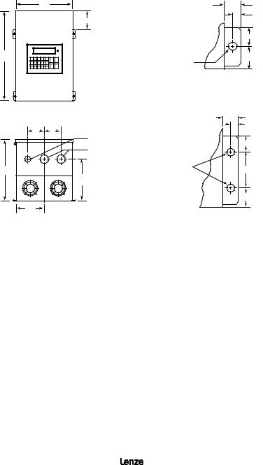
4.4TYPE 12 DIMENSIONS: MODELS RATED ABOVE 30 HP
AT 240/200 Vac AND 60 HP AT 590/480/400 Vac
W
R
H
Q |
Q |
Conduit Holes: |
|
|
|
|
|
1.13" Dia. |
|
|
S Dia. |
D |
|
|
|
|
P |
N |
|
|
0.68"
0.31"
|
1.36" |
0.36" |
1.50" |
|
|
Dia. |
|
|
IF W = 14.00" |
|
Mounting Tab Detail |
|
0.92" |
|
0.43" |
|
1.36" |
0.44" |
3.00" |
Dia. |
|
IF W > 18.00" |
1.50" |
|
HP/kW |
INPUT |
MODEL |
H |
W |
D |
N |
P |
Q |
R |
S |
|
VOLTAGE |
|||||||||||
|
|
|
|
|
|
|
|
|
|
|
|
75/55 |
480 |
/ 400 |
M14750D |
37.00 |
18.00 |
13.30 |
7.50 |
8.00 |
3.13 |
7.14 |
1.75 |
|
|
|
|
|
|
|
|
|
|
||
100/75 |
480 |
/ 400 M141000D 39.00 |
26.00 |
13.30 |
11.50 |
9.00 |
4.50 |
9.14 |
2.50 |
||
|
|
|
|
|
|
|
|
|
|
|
|
125/90 |
480 |
/ 400 |
M141250D 39.00 |
26.00 |
13.30 |
11.50 |
9.00 |
4.50 |
9.14 |
2.50 |
|
|
|
|
|
|
|
|
|
|
|
|
|
13435742_EDBM101_v24 |
9 |

5 MC1000 RATINGS
The following tables indicate the input and output ratings of the MC1000 Series.
NOTE: The output current ratings are based on operation at carrier frequencies of 8 kHz and below. At full ambient temperature, operation at carrier frequencies above 8 kHz require derating the drive by multiplying the output current rating by the following factors: 0.94 at 10 kHz, 0.89 at 12 kHz, and 0.83 at 14 kHz. Refer to Parameter 23 - CARRIER in Section 18 - DESCRIPTION OF PARAMETERS.
NOTE
Refer to Appendix A for derated single phase ratings on selected models.
M1100 SERIES RATINGS
MODEL |
|
|
INPUT |
|
OUTPUT |
||
|
(120/240 Vac, 50 - 60 Hz) |
(0 - 230 Vac) |
|||||
|
|
|
|||||
|
|
|
|
|
|
|
|
|
FOR MOTORS |
|
NOMINAL |
|
NOMINAL |
|
|
MODEL |
RATED |
INPUT |
CURRENT2 |
POWER |
CURRENT |
POWER |
|
NUMBER1 |
|||||||
|
HP |
kW |
PHASE |
(AMPS) |
(KVA) |
(AMPS) |
(KVA) |
|
|
|
|
|
|
|
|
M1103S |
0.25 |
0.18 |
1 |
6.0 / 3.0 |
0.72 |
1.4 / 1.4 |
0.56 |
|
|
|
|
|
|
|
|
M1105S |
0.5 |
0.37 |
1 |
9.2 / 4.6 |
1.1 |
2.2 / 2.2 |
0.88 |
|
|
|
|
|
|
|
|
M1110S |
1 |
0.75 |
1 |
16.2 / 8.1 |
1.9 |
4.0 / 4.0 |
1.6 |
|
|
|
|
|
|
|
|
M1115S |
1.5 |
1.1 |
1 |
21 / 10.4 |
2.5 |
5.2 / 5.2 |
2.1 |
|
|
|
|
|
|
|
|
1Refer to Section 3 for model number breakdown.
2Refer to Section 8 for recommended fuse type.
10 |
13435742_EDBM101_v24 |

M1200 SERIES RATINGS
|
MODEL |
|
|
INPUT |
|
|
OUTPUT |
|||
|
|
(200/240 Vac, 50 - 60 Hz) |
(0 - 200/230 Vac) |
|||||||
|
|
|
|
|||||||
|
|
|
|
|
|
|
|
|
||
|
|
FOR MOTORS |
|
NOMINAL |
|
NOMINAL |
|
|||
MODEL |
|
RATED |
INPUT |
CURRENT2 |
POWER |
CURRENT |
POWER |
|||
NUMBER1 |
||||||||||
|
|
HP |
kW |
PHASE |
(AMPS) |
(KVA) |
(AMPS) |
(KVA) |
||
|
|
|
|
|
|
|
|
|
|
|
M1205S |
0.5 |
0.37 |
1 |
5.8 |
/ 5.0 |
1.2 |
2.5 |
/ 2.2 |
0.9 |
|
|
|
|
|
|
|
|
|
|
|
|
M1205 |
|
0.5 |
0.37 |
3 |
3.1 |
/ 2.7 |
1.1 |
2.5 |
/ 2.2 |
0.9 |
|
|
|
|
|
|
|
|
|
||
M1210S |
1 |
0.75 |
1 |
10.4 / 9.0 |
2.2 |
4.6 |
/ 4.0 |
1.6 |
||
|
|
|
|
|
|
|
|
|
|
|
M1210 |
|
1 |
0.75 |
3 |
5.5 |
/ 4.8 |
2.0 |
4.6 |
/ 4.0 |
1.6 |
|
|
|
|
|
|
|
|
|
|
|
M1215S |
1.5 |
1.1 |
1 |
13.3 |
/ 11.6 |
2.8 |
6.0 |
/ 5.2 |
2.1 |
|
|
|
|
|
|
|
|
|
|
|
|
M1215 |
|
1.5 |
1.1 |
3 |
7.1 |
/ 6.2 |
2.6 |
6.0 |
/ 5.2 |
2.1 |
|
|
|
|
|
|
|
|
|
|
|
M1220S |
2 |
1.5 |
1 |
17.1 |
/ 14.9 |
3.6 |
7.8 |
/ 6.8 |
2.7 |
|
|
|
|
|
|
|
|
|
|
|
|
M1220 |
|
2 |
1.5 |
3 |
9.3 |
/ 8.1 |
3.4 |
7.8 |
/ 6.8 |
2.7 |
|
|
|
|
|
|
|
|
|
||
M1230S |
3 |
2.2 |
1 |
24 |
/ 21 |
5.0 |
11.0 / 9.6 |
3.8 |
||
|
|
|
|
|
|
|
|
|
|
|
M1230 |
|
3 |
2.2 |
3 |
13.0 |
/ 11.3 |
4.7 |
11.0 / 9.6 |
3.8 |
|
|
|
|
|
|
|
|
|
|
|
|
M1250 |
|
5 |
3.7 |
3 |
20 / 17.7 |
7.4 |
17.5 |
/ 15.2 |
6.1 |
|
|
|
|
|
|
|
|
|
|
|
|
M1275 |
|
7.5 |
5.5 |
3 |
30 |
/ 26 |
10.6 |
25 |
/ 22 |
8.8 |
|
|
|
|
|
|
|
|
|
|
|
M12100 |
10 |
7.5 |
3 |
37 |
/ 32 |
13.2 |
32 |
/ 28 |
11.2 |
|
|
|
|
|
|
|
|
|
|
|
|
M12150 |
15 |
11 |
3 |
55 |
/ 48 |
19.8 |
48 |
/ 42 |
16.7 |
|
|
|
|
|
|
|
|
|
|
|
|
M12200 |
20 |
15 |
3 |
70 |
/ 61 |
25.3 |
62 |
/ 54 |
21.5 |
|
|
|
|
|
|
|
|
|
|
|
|
M12250 |
25 |
18.5 |
3 |
89 |
/ 77 |
32.0 |
78 |
/ 68 |
27.1 |
|
|
|
|
|
|
|
|
|
|
||
M12300 |
30 |
22 |
3 |
104 / 90 |
37.6 |
92 |
/ 80 |
31.9 |
||
|
|
|
|
|
|
|
|
|
|
|
M12400 |
3 |
40 |
30 |
3 |
119 / 99 |
41.0 |
120 |
/ 104 |
41.4 |
|
|
|
|
|
|
|
|
|
|
|
|
M12600 |
3 |
60 |
45 |
3 |
174 |
/ 145 |
60.5 |
177 |
/ 154 |
61.3 |
|
|
|
|
|
|
|
|
|
|
|
1Refer to Section 3 for model number breakdown.
2Refer to Section 8 for recommended fuse type.
3For branch circuit protection, the 40HP and 60HP 230V models must only be installed with the appropriately rated UL Listed fuses.
13435742_EDBM101_v24 |
11 |

M1400 SERIES RATINGS
MODEL |
|
|
INPUT |
|
|
OUTPUT |
|||
|
(400/480 Vac, 50 - 60 Hz) |
(0 - 400/460 Vac) |
|||||||
|
|
|
|||||||
|
|
|
|
|
|
|
|
||
|
FOR MOTORS |
|
NOMINAL |
|
NOMINAL |
|
|||
MODEL |
RATED |
INPUT |
CURRENT2 |
POWER |
CURRENT |
POWER |
|||
NUMBER1 |
|||||||||
|
HP |
kW |
PHASE |
(AMPS) |
(KVA) |
(AMPS) |
(KVA) |
||
|
|
|
|
|
|
|
|
|
|
M1410 |
1 |
0.75 |
3 |
2.8 |
/ 2.4 |
2.0 |
2.3 |
/ 2.0 |
1.6 |
|
|
|
|
|
|
|
|
|
|
M1420 |
2 |
1.5 |
3 |
4.7 |
/ 4.1 |
3.4 |
3.9 |
/ 3.4 |
2.7 |
|
|
|
|
|
|
|
|
|
|
M1430 |
3 |
2.2 |
3 |
6.6 |
/ 5.7 |
4.7 |
5.5 |
/ 4.8 |
3.8 |
|
|
|
|
|
|
|
|
|
|
M1450 |
5 |
3.7 |
3 |
10.2 / 8.9 |
7.3 |
8.7 |
/ 7.6 |
6.1 |
|
|
|
|
|
|
|
|
|
|
|
M1475 |
7.5 |
5.5 |
3 |
14.7 |
/ 12.8 |
10.6 |
12.6 |
/ 11.0 |
8.8 |
|
|
|
|
|
|
|
|
|
|
M14100 |
10 |
7.5 |
3 |
18.3 |
/ 15.9 |
13.2 |
16.0 |
/ 14.0 |
11.2 |
|
|
|
|
|
|
|
|
|
|
M14150 |
15 |
11 |
3 |
28 |
/ 24 |
19.8 |
24 |
/ 21 |
16.7 |
|
|
|
|
|
|
|
|
|
|
M14200 |
20 |
15 |
3 |
36 |
/ 31 |
25.3 |
31 |
/ 27 |
21.5 |
|
|
|
|
|
|
|
|
|
|
M14250 |
25 |
18.5 |
3 |
44 |
/ 38 |
31.9 |
39 |
/ 34 |
27.1 |
|
|
|
|
|
|
|
|
|
|
M14300 |
30 |
22 |
3 |
52 |
/ 45 |
37.6 |
46 |
/ 40 |
31.9 |
|
|
|
|
|
|
|
|
|
|
M14400 |
40 |
30 |
3 |
68 |
/ 59 |
49.0 |
60 |
/ 52 |
41.4 |
|
|
|
|
|
|
|
|
|
|
M14500 |
50 |
37.5 |
3 |
85 |
/ 74 |
61.5 |
75 |
/ 65 |
51.8 |
|
|
|
|
|
|
|
|
|
|
M14600 |
60 |
45 |
3 |
100 / 87 |
72.3 |
88 |
/ 77 |
61.3 |
|
|
|
|
|
|
|
|
|
||
M14750 |
75 |
55 |
3 |
109 / 91 |
75.5 |
110 / 96 |
76.5 |
||
|
|
|
|
|
|
|
|
|
|
M141000 |
100 |
75 |
3 |
139 |
/ 116 |
96.4 |
143 |
/ 124 |
98.8 |
|
|
|
|
|
|
|
|
|
|
M141250 |
125 |
90 |
3 |
175 |
/ 146 |
121.4 |
179 |
/ 156 |
124.3 |
|
|
|
|
|
|
|
|
|
|
M141500 |
150 |
110 |
3 |
202 |
/ 168 |
139.7 |
207 |
/ 180 |
143.4 |
|
|
|
|
|
|
|
|
|
|
1Refer to Section 3 for model number breakdown.
2Refer to Section 8 for recommended fuse type.
12 |
13435742_EDBM101_v24 |

M1500 SERIES RATINGS
MODEL |
|
|
INPUT |
|
|
OUTPUT |
|||
|
(480/590 Vac, 50 - 60 Hz) |
(0 - 460/575 Vac) |
|||||||
|
|
|
|||||||
|
|
|
|
|
|
|
|
||
|
FOR MOTORS |
|
NOMINAL |
|
NOMINAL |
|
|||
MODEL |
RATED |
INPUT |
CURRENT2 |
POWER |
CURRENT |
POWER |
|||
NUMBER1 |
|||||||||
|
HP |
kW |
PHASE |
(AMPS) |
(KVA) |
(AMPS) |
(KVA) |
||
|
|
|
|
|
|
|
|
|
|
M1510 |
1 |
0.75 |
3 |
1.9 |
/ 1.9 |
1.9 |
1.6 |
/ 1.6 |
1.6 |
|
|
|
|
|
|
|
|
|
|
M1520 |
2 |
1.5 |
3 |
3.3 |
/ 3.3 |
3.4 |
2.7 |
/ 2.7 |
2.7 |
|
|
|
|
|
|
|
|
|
|
M1530 |
3 |
2.2 |
3 |
4.6 |
/ 4.6 |
4.7 |
3.9 |
/ 3.9 |
3.9 |
|
|
|
|
|
|
|
|
|
|
M1550/51 |
5 |
3.7 |
3 |
7.1 |
/ 7.1 |
7.3 |
6.1 |
/ 6.1 |
6.1 |
|
|
|
|
|
|
|
|
|
|
M1575 |
7.5 |
5.5 |
3 |
10.5 |
/ 10.5 |
10.7 |
9.0 |
/ 9.0 |
8.8 |
|
|
|
|
|
|
|
|
|
|
M15100 |
10 |
7.5 |
3 |
12.5 |
/ 12.5 |
12.8 |
11.0 |
/ 11.0 |
11.0 |
|
|
|
|
|
|
|
|
|
|
M15150 |
15 |
11 |
3 |
19.3 |
/ 19.3 |
19.7 |
17.0 |
/ 17.0 |
16.9 |
|
|
|
|
|
|
|
|
|
|
M15200 |
20 |
15 |
3 |
25 |
/ 25 |
25.4 |
22 |
/ 22 |
21.5 |
|
|
|
|
|
|
|
|
|
|
M15250 |
25 |
18.5 |
3 |
31 |
/ 31 |
31.2 |
27 |
/ 27 |
26.9 |
|
|
|
|
|
|
|
|
|
|
M15300 |
30 |
22 |
3 |
36 |
/ 36 |
37.1 |
32 |
/ 32 |
31.9 |
|
|
|
|
|
|
|
|
|
|
M15400 |
40 |
30 |
3 |
47 |
/ 47 |
47.5 |
41 |
/ 41 |
40.8 |
|
|
|
|
|
|
|
|
|
|
M15500 |
50 |
37.5 |
3 |
59 |
/ 59 |
60.3 |
52 |
/ 52 |
51.8 |
|
|
|
|
|
|
|
|
|
|
M15600 |
60 |
45 |
3 |
71 |
/ 71 |
72.5 |
62 |
/ 62 |
61.7 |
|
|
|
|
|
|
|
|
|
|
1Refer to Section 3 for model number breakdown.
2Refer to Section 8 for recommended fuse type.
13435742_EDBM101_v24 |
13 |

6 THEORY
6.1DESCRIPTION OF AC MOTOR OPERATION
Three phase AC motors are comprised of two major components, the stator and the rotor. The stator is a set of three electrical windings held stationary in the motor housing. The rotor is a metal cylinder, fixed to the motor drive shaft, which rotates within the stator. The arrangement of the stator coils and the presence of three phase AC voltage give rise to a rotating magnetic field which drives the rotor. The speed at which the magnetic field rotates is known as the synchronous speed of the motor. Synchronous speed is a function of the frequency at which the voltage is alternating and the number of poles in the stator windings.
The following equation gives the relation between synchronous speed, frequency, and the number of poles:
Ss = 120 f/p
Where: Ss = Synchronous speed (rpm ), f = frequency (Hz), p = number of poles
In three phase induction motors the actual shaft speed differs from the synchronous speed as load is applied. This difference is known as “slip”. Slip is commonly expressed as a percentage of synchronous speed. A typical value is three percent at full load.
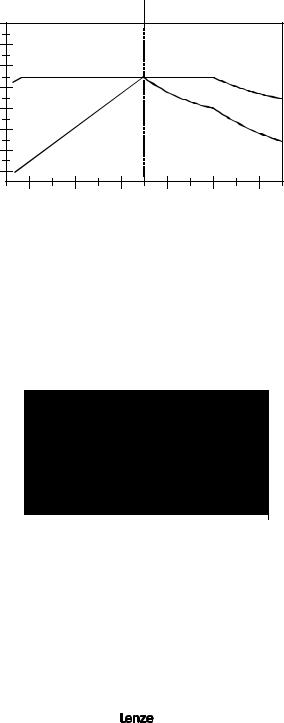
The strength of the magnetic field in the gap between the rotor and stator is proportional to the amplitude of the voltage at a given frequency. The output torque capability of the motor is, therefore, a function of the applied voltage amplitude at a given frequency. When operated below base (rated) speed, AC motors run in the range of “constant torque”. Constant torque output is obtained by maintaining a constant ratio between voltage amplitude (Volts) and frequency (Hertz). For 60 Hz motors rated at 230, 460, and 575 Vac, common values for this V/Hz ratio are 3.83, 7.66, and 9.58 respectively. Operating with these V/Hz ratios generally yields optimum torque capability. Operating at lower ratio values results in lower torque and power capability. Operating at higher ratio values will cause the motor to overheat. Most standard motors are capable of providing full torque output from 3 to 60 Hz. However, at lower speeds, where motor cooling fans become less effective, supplemental cooling may be needed to operate at full torque output continuously.
If the frequency applied to the motor is increased while the voltage remains constant, torque capability will decrease as speed increases. This will cause the horsepower capability of the motor to remain approximately constant. Motors run in this mode when operated above base speed, where drive output voltage is limited by the input line voltage. This operating range is known as the “constant horsepower” range. The typical maximum range for constant horsepower is about 2.3 to 1 (60 to 140 Hz). The diagram below depicts the characteristics of a typical AC induction motor with a 60 Hz base speed.
WARNING!
Consult motor manufacturer before operating motor and/or driven equipment above base speed.
14 |
13435742_EDBM101_v24 |
|
150 |
CONSTANT TORQUE |
|
CONSTANT HP |
|
|
|
|
|
|
|
|
|
|
|
|
130 |
|
|
|
|
|
|
|
110 |
TORQUE |
|
|
HORSEPOWER |
|
|
|
|
|
|
|
|
||
(%) |
90 |
|
|
|
TORQUE |
|
|
TORQUE |
|
|
|
|
|
||
|
|
|
|
|
|
||
70 |
HORSEPOWER |
|
|
|
|
|
|
|
|
|
|
|
|
||
|
50 |
|
|
|
|
|
|
|
30 |
|
|
|
|
|
|
|
10 |
|
|
|
|
|
|
|
|
20 |
40 |
60 |
80 |
100 |
120 |
FREQUENCY (Hz)
6.1.1VARIABLE TORQUE VS. CONSTANT TORQUE
Variable frequency drives, and the loads they are applied to, can generally be divided into two groups: constant torque and variable torque. Constant torque loads include: vibrating conveyors, punch presses, rock crushers, machine tools, and just about every other application that is not considered variable torque. Variable torque loads include centrifugal pumps and fans, which make up the majority of HVAC applications.
Variable torque loads are governed by the affinity laws, which define the relationships between speed, flow, torque and horsepower. The diagram below illustrates these relationships:
100%
75%
50%
25%
0%
|
|
|
FLOW |
|
|
|
|
|
|
|
|
||
|
|
|
|
|||
% |
|
|
|
|||
|
|
|
|
TORQUE |
||
% |
HORSEPOWER |
|||||
|
|
|
|
|
% |
|
|
|
|
|
|
|
|
|
|
|
|
|
|
|
|
|
|
|
|
|
|
0% |
25% |
50% |
75% |
100% |
|
|
% SPEED |
|
|
“Variable torque” refers to the fact that the torque required varies with the square of the speed. Also, the horsepower required varies with the cube of the speed, resulting in a large reduction in horsepower for even a small reduction in speed. It is easily seen that substantial energy savings can be achieved by reducing the speed of a fan or pump. For example, reducing the speed to 50% results in a 50 HP motor having to produce only 12.5% of rated horsepower, or 6.25 HP.
Variable torque drives usually have a low overload capacity (110% - 120% for 60 seconds), because variable torque applications rarely experience overload conditions. To optimize efficiency and energy savings, variable torque drives are usually programmed to follow a variable V/Hz ratio.
13435742_EDBM101_v24 |
15 |

The term “constant torque” is not entirely accurate in terms of the actual torque required for an application. Many constant torque applications have reciprocating loads, such as vibrating conveyors and punch presses, where the rotational motion of the motor is being converted to a linear motion. In such cases, the torque required can vary greatly at different points in the cycle. For constant torque loads, this fluctuation in torque is not a direct function of speed, as it is with a variable torque load. As a result, constant torque drives typically have a high overload rating (150% for 60 seconds) in order to handle the higher peak torque demands. To achieve maximum torque, constant torque drives follow a constant V/Hz ratio.
Both MC Series product lines (MC1000 and MC3000) have full overload capacity (150% for 60 seconds, 180% for 30 seconds), so that either one can be used for either type of application. The V/Hz ratio can also be changed to optimize performance for either type of application.
6.2DRIVE FUNCTION DESCRIPTION
The MC Series is a 16 bit microprocessor based, keypad programmable, variable speed AC motor drive. There are four major sections: an input diode bridge and filter, a power board, a control board, and an output intelligent power module.
6.2.1DRIVE OPERATION
Incoming AC line voltage is converted to a pulsating DC voltage by the input diode bridge. The DC voltage is supplied to the bus filter capacitors through a charge circuit which limits inrush current to the capacitors during power-up. The pulsating DC voltage is filtered by the bus capacitors which reduces the ripple level. The filtered DC voltage enters the inverter section of the drive, composed of six output intelligent insulated gate bi-polar transistors (IGBTs) which make up the three output legs of the drive. Each leg has one intelligent IGBT connected to the positive bus voltage and one connected to the negative bus voltage. Alternately switching on each leg, the intelligent IGBT produces an alternating voltage on each of the corresponding motor windings. By switching each output intelligent IGBT at a very high frequency (known as the carrier frequency) for varying time intervals, the inverter is able to produce a smooth, three phase, sinusoidal output current wave which optimizes motor performance.
6.2.2CIRCUIT DESCRIPTION
The control section consists of a control board with a 16 bit microprocessor, keypad and display. Drive programming is accomplished via the keypad or the serial communications port. During operation the drive can be controlled via the keypad, by control devices wired to the control terminal strip, or by the serial communications port. The Power Board contains the control and protection circuits which govern the six output IGBTs. The Power Board also contains a charging circuit for the bus filter capacitors, a motor current feedback circuit, a voltage feedback circuit, and a fault signal circuit. The drive has several built in protection circuits. These include phase-to-phase and phase-to-ground short circuit protection, high and low line voltage protection, protection against excessive ambient temperature, and protection against continuous excessive output current. Activation of any of these circuits will cause the drive to shut down in a fault condition.
16 |
13435742_EDBM101_v24 |
6.2.3MC1000 INPUTS AND OUTPUTS
The drive has two analog inputs (0-10 VDC and 4-20 mA) that can be used for speed reference, PID set point reference, or PID feedback. A speed potentiometer (10,000 Ohm) can be used with the 0-10 VDC input.
There are also two analog outputs: one is proportional to speed (frequency), and the other is proportional to load.
The drive has three programmable outputs for status indication: one Form C relay and two open-collector outputs.
NOTE: Models rated above 30 Hp at 200/240 Vac and 60 Hp at 400/480 Vac have a second Form C relay.
Refer to Sections 14 - CONTROL WIRING and 15 - CONTROL WIRING DIAGRAMS for more information.
7 INSTALLATION
WARNING!
Drives must not be installed where subjected to adverse environmental conditions! Drives must not be installed where subjected to: combustible, oily, or hazardous vapors or dust; excessive moisture or dirt; strong vibration; excessive ambient temperatures. Consult Lenze AC Tech for more information on the suitability of a drive to a particular environment
The drive should be mounted on a smooth vertical surface capable of safely supporting the unit without vibrating. The LCD display has an optimum field of view, this should be considered when determining the mounting position.
Chassis models must be installed in an electrical enclosure that will provide complete mechanical protection and maintain uniform internal temperature within the drive’s ambient operating temperature rating. All drive models MUST be mounted in a vertical position for proper heatsink cooling.
Maintain a minimum spacing around the drive as follows:
SPACING REQUIREMENTS
HP |
SPACING |
|
|
INCHES |
|
mm |
|
|
|
||
0.25 - 5 |
2 |
|
50 |
|
|
|
|
7.5 - 25 |
4 |
|
100 |
|
|
|
|
30 - 60 |
6 |
|
150 |
|
|
|
|
75 - 150 |
8 |
|
200 |
|
|
|
|
All drive models MUST be mounted in a vertical position for proper heatsink cooling. Fans or blowers should be used to insure proper cooling in tight quarters. Do not mount drives above other drives or heat producing equipment that would impede the cooling of the drive. Note the ambient operating temperature ratings for each drive model.
13435742_EDBM101_v24 |
17 |

If it is necessary to drill or cut the drive enclosure or panel, extreme care must be taken to avoid damaging drive components or contaminating the drive with metal fragments (which cause shorting of electrical circuits). Cover drive components with a clean cloth to keep out metal chips and other debris. Use a vacuum cleaner to clean drive components after drilling, even if chips do not appear to be present. Do not attempt to use positive air pressure to blow chips out of drive, as this tends to lodge debris under electronic components. Contaminating the drive with metal chips can cause drive failure and will void the warranty. The MC1000 Series is UL approved for solid state motor overload protection. Therefore, a separate thermal overload relay is not required for single motor applications. In applications where one drive is operating more than one motor, a separate thermal overload relay is required for each motor per NEC.
7.1INSTALLATION AFTER A LONG PERIOD OF STORAGE
WARNING!
Severe damage to the drive can result if it is operated after a long period of storage or inactivity without reforming the DC bus capacitors!
If input power has not been applied to the drive for a period of time exceeding three years (due to storage, etc), the electrolytic DC bus capacitors within the drive can change internally, resulting in excessive leakage current. This can result in premature failure of the capacitors if the drive is operated after such a long period of inactivity or storage.
In order to reform the capacitors and prepare the drive for operation after a long period of inactivity, apply input power to the drive for 8 hours prior to actually operating the drive/motor system.
7.2EXPLOSION PROOF APPLICATIONS
Explosion proof motors that are not rated for inverter use lose their certification when used for variable speed. Due to the many areas of liability that may be encountered when dealing with these applications, the following statement of policy applies:
“Lenze AC Tech Corporation inverter products are sold with no warranty of fitness for a particular purpose or warranty of suitability for use with explosion proof motors. Lenze AC Tech Corporation accepts no responsibility for any direct, incidental or consequential loss, cost, or damage that may arise through the use of its AC inverter products in these applications. The purchaser expressly agrees to assume all risk of any loss, cost, or damage that may arise from such application."
18 |
13435742_EDBM101_v24 |

8 INPUT AC REQUIREMENTS
WARNING!
Hazard of electrical shock! Disconnect incoming power and wait three minutes before servicing the drive. Capacitors retain charge after power is removed.
8.1INPUT AC POWER REQUIREMENTS
8.1.1VOLTAGE
The input voltage must match the drive’s nameplate voltage rating. Voltage fluctuation must not vary by greater than 10% over voltage or 15% under voltage.
NOTE: Drives with dual rated input voltage must be programmed for the proper supply voltage. Refer to Parameter 0 - LINE VOLTS in Section 18 - DESCRIPTION OF PARAMETERS.
The UL file for this drive shows that it is suitable for use on a circuit capable of delivering not more than 200,000 RMS symmetrical amperes, at the drive’s rated voltage. The CSA file identifies a short-circuit withstand rating of 5,000 RMS symmetrical amperes at the drives rated voltage.
Three phase voltage imbalance must be less than 2.0% phase to phase. Excessive phase to phase imbalance can cause severe damage to the drive’s power components.
Motor voltage should match line voltage in normal applications. The drive’s maximum output voltage will equal the input voltage. Use extreme caution when using a motor with a voltage rating which is different from the input line voltage.
8.1.2SUPPLY TRANSFORMER kVA RATINGS
If the kVA rating of the AC supply transformer is greater than ten times the input kVA rating of the drive, a drive isolation transformer, or a 2 - 3% input line reactor (also known as a choke) must be added.
8.2INPUT FUSING AND DISCONNECT REQUIREMENTS
A circuit breaker or a disconnect switch with fuses must be provided in accordance with the National Electric Code (NEC) and all local codes.
The MC1000 drive is capable of withstanding up to 150% current overload for 60 seconds. Select a fuse or magnetic trip circuit breaker rated at 1.5 times the input current rating of the drive (the minimum size should be 10 amps, regardless of input current rating). Refer to Section 5 - MC1000 RATINGS. Minimum voltage rating of the protection device should be 250 Vac for 240/120 Vac and 240/200 Vac rated drives, and 600 Vac for 480/400 Vac and 590/480 Vac drives.
Use UL Class CC or Class T current-limiting type fuses with low I 2 T values, rated at 200,000 AIC. Recommended fuses are Bussman type KTK-R, JJN, and JJS, or equivalent.
WARNING!
Per UL requirements, use a FUSE (not a circuit breaker) for 240VAC drives requiring >40A protection and for 480VAC & 600VAC drives requiring >32A protection.
13435742_EDBM101_v24 |
19 |
9 VOLTAGE SELECTION
M1100 Series drives are rated for 240/120 Vac, 50-60 Hz input. The drive will function with input voltage of 120 Vac (+ 10%, -15%) at 48 to 62 Hz when wired for 120 Vac input, or with input voltage of 240 Vac (+ 10%, - 15%), at 48 to 62 Hz, when wired for 240 Vac input.
M1200 Series drives are rated for 240/200 Vac, 50-60 Hz input. The drive will function with input voltages of 200 to 240 Vac (+ 10%, - 15%), at 48 to 62 Hz.
M1400 Series drives are rated for 480/400 Vac, 50-60 Hz input. The drive will function with input voltages of 400 to 480 Vac (+ 10%, - 15%), at 48 to 62 Hz.
M1500 Series drives are rated for 590/480 Vac, 50-60 Hz input. The drive will function with input voltages of 480 to 590 Vac (+ 10%, - 15%), at 48 to 62 Hz.
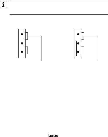
To select the proper input voltage on 240/200 VAC 40-60 Hp models, 400/480 VAC 75-150 Hp and 480/590 VAC 75-150 Hp models the PL2 plug must be in the correct position. PL2 is located either at the lower right corner, or upper right corner of the power board, depending on horsepower. The PL2 plug is used to select the correct input voltage. Plug PL2 into the top and middle pins to select 240, 480, or 590 VAC or the middle and bottom pins to select 200, 400, or 480.
NOTE:
In addition to the voltage plug selection, Parameter 0 – LINE VOLTS must also be programmed for the proper voltage. Refer to Section 18 - DESCRIPTION OF PARAMETERS.
|
|
Voltage Selection Plug (PL2) |
PL2 |
PL2 |
|
|
|
|
|
|
|
|
|
|
|
|
|
|
|
|
MODEL |
|
|
|
|
|
|
|
|
|
|
|
|
|
|
|
||
CODE |
|
|
|
|
|
|
|
|
|
|
|
|
|
|
|
||
1200 |
|
200V |
|
240V |
||||
1400 |
|
400V |
|
480V |
||||
1500 |
|
480V |
|
590V |
||||
240 / 480 / 590 Vac INPUT
|
|
|
|
|
|
|
|
|
|
|
MODEL |
|
|
|
|
|
|
|
|
|
|
|
|
|
|
|
|
|
|
|
||
|
|
|
|
|
|
|
|
|
||
CODE |
|
|
|
|
|
|
|
|
|
|
|
|
|
|
|
|
|
|
|
||
1200 |
|
|
200V |
|
240V |
|||||
1400 |
|
|
400V |
|
480V |
|||||
1500 |
|
|
480V |
|
590V |
|||||
200 / 400 / 480 Vac INPUT
20 |
13435742_EDBM101_v24 |

10 POWER WIRING
WARNING!
Hazard of electrical shock! Wait three minutes after disconnecting incoming power before servicing drive. Capacitors retain charge after power is removed.
Note drive input and output current ratings and check applicable electrical codes for required wire type and size, grounding requirements, over current protection, and incoming power disconnect, before wiring the drive. Size conservatively to minimize voltage drop.
Input fusing and a power disconnect switch or contactor MUST be wired in series with terminals L1, L2, and L3 (L1 and L2 if input is single phase). If one has not been supplied by Lenze AC Tech Corporation, a disconnect means must be wired during installation. This disconnect must be used to power down the drive when servicing, or when the drive is not to be operated for a long period of time, but should not be used to start and stop the motor.
Repetitive cycling of a disconnect or input contactor (more than once every two minutes) may cause damage to the drive.
10.1WIRING FOR SINGLE PHASE OR THREE PHASE INPUT
If the drive is name plated for 240/120 Vac single phase input, wire the input to terminals L1 and N and jumper terminals L1 to L2 for 120 Vac input voltage, or wire to terminals L1 and L2 (do not wire to N) for 240 Vac input voltage. Refer to Section 11 - MC1000 POWER WIRING DIAGRAM.
If the drive is name plated for three phase input only, wire the input to terminals L1, L2, and L3.
NOTE: Refer to Appendix A for alternate single wiring configuration on selected models.
All three power output wires, from terminals T1, T2, and T3 to the motor, must be kept tightly bundled and run in a separate conduit away from all other power and control wiring.
Do not install contactors or disconnect switches between the drive and motor. Operating such devices while the drive is running can potentially cause damage to the drive's power components. If such a device is required, it should only be operated when the drive is in a STOP state. If there is potential for the device to be opened while the drive is running, the drive must be programmed for COAST TO STOP (see Parameter 26 - STOP), and an auxiliary contact on the device must be interlocked with the drive's run circuit. This will give the drive a stop command at the same time the device opens, and will not allow the drive to start again until the device is closed.
13435742_EDBM101_v24 |
21 |
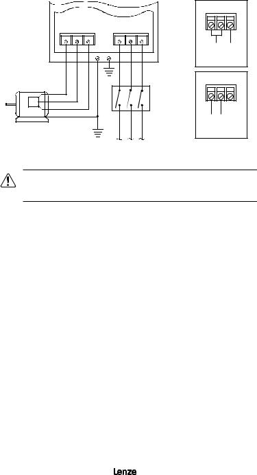
11 |
MC1000 POWER WIRING DIAGRAM |
|
|||||
|
|
|
|
|
|
|
L1 L2 N |
|
T1 |
T2 |
T3 |
L1 |
L2 |
L3 |
|
|
|
|
GND |
GND |
|
|
120 Vac SINGLE |
|
|
|
|
|
PHASE INPUT |
||
|
|
|
|
|
|
|
WIRING DIAGRAM |
|
|
|
|
|
|
|
L1 L2 N |
|
|
|
|
|
|
DISCONNECT |
240 Vac SINGLE |
|
|
|
|
|
|
MEANS |
|
|
THREE PHASE |
|
|
|
|
PHASE INPUT |
|
|
|
|
|
|
(REQUIRED) |
||
|
|
|
|
|
WIRING DIAGRAM |
||
|
AC MOTOR |
|
GND |
|
|
|
|
|
|
|
|
|
|
||
|
|
|
|
FUSED INPUT |
|
||
|
|
|
|
VOLTAGE |
|
||
WARNING!
Do not connect incoming AC power to output terminals T1, T2, or T3! Severe damage to the drive will result.
INSTALL, WIRE, AND GROUND IN ACCORDANCE WITH ALL APPLICABLE CODES.
NOTES:
1.Wire the motor for the proper voltage per the output rating of the drive. Motor wires MUST be run in a separate steel conduit away from control wiring and incoming AC power wiring.
2.Do not install contactors between the drive and the motor. Damage to the drive may result. Refer to Section 10.1.
3.Remove any existing, and do not install, power factor correction capacitors between the drive and the motor. Failure to do so will result in drive damage.
4.Use only UL and CSA listed and approved wire.
5.Minimum wire voltage ratings: 300 V for 120, 200 and 240 Vac systems, and 600 V for 400, 480, and 590 Vac systems.
6.Wire gauge must be based on a minimum of 125% of the rated input/output current of the drive, and a minimum 75°C insulation rating. Use copper wire only.
7.Wire and ground in accordance with NEC or CEC, and all applicable local codes.
8.Refer to Appendix A for alternate single phase wiring configuration on selected models.
22 |
13435742_EDBM101_v24 |
 Loading...