


 Loading...
Inverter
8400 |
E84AVBCxxxxx... |
Inverter Drives 8400 BaseLine C _ _ _ _ _ _ _ _ _ _ _ _ _ _ |
Reference manual |
EN |
Ä.>ZVä 13295753
L

Overview of technical documentation for Inverter Drives 8400
_ _ _ _ _ _ _ _ _ _ _ _ _ _ _ _ _ _ _ _ _ _ _ _ _ _ _ _ _ _ _ _ _ _ _ _ _ _ _ _ _ _ _ _ _ _ _ _ _ _ _ _ _ _ _ _ _ _ _ _ _ _ _ _
Project planning, selection & ordering |
|
Legend: |
|
Hardware manual 8400 BaseLine C/D |
|
Printed documentation |
|
Catalogue |
|
Online documentation |
|
|
|
|
(PDF/Engineer online help) |
|
|
|
|
|
|
|
|
Mounting & wiring |
|
Abbreviations used: |
|
MA 8400 BaseLine C |
|
BA |
Operating Instructions |
MA for the accessories |
|
KHB |
Communication manual |
|
|
MA |
Mounting instructions |
|
|
||
|
|
|
|
Parameterisation |
|
SW |
Software/reference manual |
|
|
|
|
SW 8400 BaseLine C |
This documentation |
||
|
|
|
|
|
|
|
|
Drive commissioning |
|
|
|
SW 8400 BaseLine C |
This documentation |
||
Chapter "Commissioning"
Chapter "Diagnostics & error management"
Remote maintenance manual
Networking
KHB for the communication medium usedMA for the accessories
2 |
Lenze · 8400 BaseLine C · Reference manual · DMS 1.6 EN · 01/2014 · TD05 |
Contents
_ _ _ _ _ _ _ _ _ _ _ _ _ _ _ _ _ _ _ _ _ _ _ _ _ _ _ _ _ _ _ _ _ _ _ _ _ _ _ _ _ _ _ _ _ _ _ _ _ _ _ _ _ _ _ _ _ _ _ _ _ _ _ _
1 |
About this documentation _ _ _ _ _ _ _ _ _ _ _ _ _ _ _ _ _ _ _ _ _ _ _ _ _ _ _ _ _ _ _ _ _ _ _ _ _ _ _ |
8 |
|||||||||
1.1 |
Document history |
_ _ _ _ _ _ _ _ _ _ _ _ _ _ _ _ _ _ _ _ _ _ _ _ _ _ _ _ _ _ _ _ _ _ _ _ _ _ _ _ _ _ _ _ |
8 |
||||||||
1.2 |
Conventions used |
_ _ _ _ _ _ _ _ _ _ _ _ _ _ _ _ _ _ _ _ _ _ _ _ _ _ _ _ _ _ _ _ _ _ _ _ _ _ _ _ _ _ _ _ |
9 |
||||||||
1.3 |
Terminology used |
_ _ _ _ _ _ _ _ _ _ _ _ _ _ _ _ _ _ _ _ _ _ _ _ _ _ _ _ _ _ _ _ _ _ _ _ _ _ _ _ _ _ _ _ |
10 |
||||||||
1.4 |
Definition of the notes used |
_ _ _ _ _ _ _ _ _ _ _ _ _ _ _ _ _ _ _ _ _ _ _ _ _ _ _ _ _ _ _ _ _ _ _ _ _ _ |
11 |
||||||||
2 |
Introduction: Parameterising the controller _ _ _ _ _ _ _ _ _ _ _ _ _ _ _ _ _ _ _ _ _ _ _ _ _ _ _ _ _ _ |
12 |
|||||||||
2.1 |
General notes on parameters _ _ _ _ _ _ _ _ _ _ _ _ _ _ _ _ _ _ _ _ _ _ _ _ _ _ _ _ _ _ _ _ _ _ _ _ _ _ |
13 |
|||||||||
2.2 |
Handling the memory module _ _ _ _ _ _ _ _ _ _ _ _ _ _ _ _ _ _ _ _ _ _ _ _ _ _ _ _ _ _ _ _ _ _ _ _ _ |
14 |
|||||||||
2.3 |
Internal Keypad |
_ _ _ _ _ _ _ _ _ _ _ _ _ _ _ _ _ _ _ _ _ _ _ _ _ _ _ _ _ _ _ _ _ _ _ _ _ _ _ _ _ _ _ _ _ |
17 |
||||||||
|
2.3.1 |
Display elements and control panel _ _ _ _ _ _ _ _ _ _ _ _ _ _ _ _ _ _ _ _ _ _ _ _ _ _ _ _ _ |
17 |
||||||||
|
2.3.2 |
LED status display |
_ _ _ _ _ _ _ _ _ _ _ _ _ _ _ _ _ _ _ _ _ _ _ _ _ _ _ _ _ _ _ _ _ _ _ _ _ _ |
18 |
|||||||
|
2.3.3 |
Display messages _ _ _ _ _ _ _ _ _ _ _ _ _ _ _ _ _ _ _ _ _ _ _ _ _ _ _ _ _ _ _ _ _ _ _ _ _ _ _ |
19 |
||||||||
|
2.3.4 |
Menu structure _ _ _ _ _ _ _ _ _ _ _ _ _ _ _ _ _ _ _ _ _ _ _ _ _ _ _ _ _ _ _ _ _ _ _ _ _ _ _ _ |
21 |
||||||||
|
2.3.5 |
User menu |
_ _ _ _ _ _ _ _ _ _ _ _ _ _ _ _ _ _ _ _ _ _ _ _ _ _ _ _ _ _ _ _ _ _ _ _ _ _ _ _ _ _ |
22 |
|||||||
|
2.3.6 |
Quick saving of all parameters at the push of a button |
_ _ _ _ _ _ _ _ _ _ _ _ _ _ _ _ _ _ |
23 |
|||||||
|
2.3.7 |
Password protection _ _ _ _ _ _ _ _ _ _ _ _ _ _ _ _ _ _ _ _ _ _ _ _ _ _ _ _ _ _ _ _ _ _ _ _ _ |
23 |
||||||||
3 |
Commissioning |
_ _ _ _ _ _ _ _ _ _ _ _ _ _ _ _ _ _ _ _ _ _ _ _ _ _ _ _ _ _ _ _ _ _ _ _ _ _ _ _ _ _ _ _ _ |
25 |
||||||||
3.1 |
Safety instructions with regard to commissioning |
_ _ _ _ _ _ _ _ _ _ _ _ _ _ _ _ _ _ _ _ _ _ _ _ _ _ |
25 |
||||||||
3.2 |
Preparing the 8400 BaseLine for commissioning |
_ _ _ _ _ _ _ _ _ _ _ _ _ _ _ _ _ _ _ _ _ _ _ _ _ _ _ |
26 |
||||||||
3.3 |
Commissioning with integrated keypad _ _ _ _ _ _ _ _ _ _ _ _ _ _ _ _ _ _ _ _ _ _ _ _ _ _ _ _ _ _ _ _ |
27 |
|||||||||
|
3.3.1 |
Load Lenze setting |
_ _ _ _ _ _ _ _ _ _ _ _ _ _ _ _ _ _ _ _ _ _ _ _ _ _ _ _ _ _ _ _ _ _ _ _ _ _ |
27 |
|||||||
|
3.3.2 |
Parameterise drive/application _ _ _ _ _ _ _ _ _ _ _ _ _ _ _ _ _ _ _ _ _ _ _ _ _ _ _ _ _ _ _ |
28 |
||||||||
|
3.3.3 |
Save parameter settings safe against mains failure _ _ _ _ _ _ _ _ _ _ _ _ _ _ _ _ _ _ _ _ |
29 |
||||||||
|
3.3.4 |
Enable controller and select speed |
_ _ _ _ _ _ _ _ _ _ _ _ _ _ _ _ _ _ _ _ _ _ _ _ _ _ _ _ _ |
30 |
|||||||
3.4 |
Commissioning with the »Engineer« _ _ _ _ _ _ _ _ _ _ _ _ _ _ _ _ _ _ _ _ _ _ _ _ _ _ _ _ _ _ _ _ _ _ |
31 |
|||||||||
|
3.4.1 |
Preconditions for commissioning with the »Engineer« |
_ _ _ _ _ _ _ _ _ _ _ _ _ _ _ _ _ _ |
31 |
|||||||
|
3.4.2 |
Creating an »Engineer« project & going online _ _ _ _ _ _ _ _ _ _ _ _ _ _ _ _ _ _ _ _ _ _ _ |
32 |
||||||||
|
3.4.3 |
Parameterise drive/application _ _ _ _ _ _ _ _ _ _ _ _ _ _ _ _ _ _ _ _ _ _ _ _ _ _ _ _ _ _ _ |
33 |
||||||||
|
3.4.4 |
Save parameter settings safe against mains failure _ _ _ _ _ _ _ _ _ _ _ _ _ _ _ _ _ _ _ _ |
37 |
||||||||
|
3.4.5 |
Enable controller and select speed |
_ _ _ _ _ _ _ _ _ _ _ _ _ _ _ _ _ _ _ _ _ _ _ _ _ _ _ _ _ |
37 |
|||||||
3.5 |
PC manual control _ _ _ _ _ _ _ _ _ _ _ _ _ _ _ _ _ _ _ _ _ _ _ _ _ _ _ _ _ _ _ _ _ _ _ _ _ _ _ _ _ _ _ _ |
39 |
|||||||||
|
3.5.1 |
Activating PC manual control _ _ _ _ _ _ _ _ _ _ _ _ _ _ _ _ _ _ _ _ _ _ _ _ _ _ _ _ _ _ _ _ |
39 |
||||||||
|
3.5.2 |
Speed control _ _ _ _ _ _ _ _ _ _ _ _ _ _ _ _ _ _ _ _ _ _ _ _ _ _ _ _ _ _ _ _ _ _ _ _ _ _ _ _ _ |
42 |
||||||||
4 |
Device control (DCTRL) |
_ _ _ _ _ _ _ _ _ _ _ _ _ _ _ _ _ _ _ _ _ _ _ _ _ _ _ _ _ _ _ _ _ _ _ _ _ _ _ _ _ |
44 |
||||||||
4.1 |
Device commands _ _ _ _ _ _ _ _ _ _ _ _ _ _ _ _ _ _ _ _ _ _ _ _ _ _ _ _ _ _ _ _ _ _ _ _ _ _ _ _ _ _ _ _ |
46 |
|||||||||
|
4.1.1 |
Load Lenze setting |
_ _ _ _ _ _ _ _ _ _ _ _ _ _ _ _ _ _ _ _ _ _ _ _ _ _ _ _ _ _ _ _ _ _ _ _ _ _ |
48 |
|||||||
|
4.1.2 |
Loading parameter settings _ _ _ _ _ _ _ _ _ _ _ _ _ _ _ _ _ _ _ _ _ _ _ _ _ _ _ _ _ _ _ _ _ |
48 |
||||||||
|
4.1.3 |
Save parameter settings _ _ _ _ _ _ _ _ _ _ _ _ _ _ _ _ _ _ _ _ _ _ _ _ _ _ _ _ _ _ _ _ _ _ _ |
49 |
||||||||
|
4.1.4 |
Import EPM data _ _ _ _ _ _ _ _ _ _ _ _ _ _ _ _ _ _ _ _ _ _ _ _ _ _ _ _ _ _ _ _ _ _ _ _ _ _ _ |
50 |
||||||||
|
4.1.5 |
Enable/Inhibit controller _ _ _ _ _ _ _ _ _ _ _ _ _ _ _ _ _ _ _ _ _ _ _ _ _ _ _ _ _ _ _ _ _ _ _ |
50 |
||||||||
|
4.1.6 |
Activate/Deactivate quick stop _ _ _ _ _ _ _ _ _ _ _ _ _ _ _ _ _ _ _ _ _ _ _ _ _ _ _ _ _ _ _ |
50 |
||||||||
|
4.1.7 |
Reset error |
_ _ _ _ _ _ _ _ _ _ _ _ _ _ _ _ _ _ _ _ _ _ _ _ _ _ _ _ _ _ _ _ _ _ _ _ _ _ _ _ _ _ |
51 |
|||||||
|
4.1.8 |
Delete logbook |
_ _ _ _ _ _ _ _ _ _ _ _ _ _ _ _ _ _ _ _ _ _ _ _ _ _ _ _ _ _ _ _ _ _ _ _ _ _ _ _ |
51 |
|||||||
|
4.1.9 |
Identify motor parameters _ _ _ _ _ _ _ _ _ _ _ _ _ _ _ _ _ _ _ _ _ _ _ _ _ _ _ _ _ _ _ _ _ _ |
51 |
||||||||
|
4.1.10 |
CAN reset node _ _ _ _ _ _ _ _ _ _ _ _ _ _ _ _ _ _ _ _ _ _ _ _ _ _ _ _ _ _ _ _ _ _ _ _ _ _ _ _ |
52 |
||||||||
4.2 |
Device states _ _ _ _ _ _ _ _ _ _ _ _ _ _ _ _ _ _ _ _ _ _ _ _ _ _ _ _ _ _ _ _ _ _ _ _ _ _ _ _ _ _ _ _ _ _ _ |
53 |
|||||||||
|
4.2.1 |
Init _ _ _ _ _ _ _ _ _ _ _ _ _ _ _ _ _ _ _ _ _ _ _ _ _ _ _ _ _ _ _ _ _ _ _ _ _ _ _ _ _ _ _ _ _ _ _ |
55 |
||||||||
|
4.2.2 |
MotorIdent |
_ _ _ _ _ _ _ _ _ _ _ _ _ _ _ _ _ _ _ _ _ _ _ _ _ _ _ _ _ _ _ _ _ _ _ _ _ _ _ _ _ _ |
56 |
|||||||
|
4.2.3 |
SafeTorqueOff |
_ _ _ _ _ _ _ _ _ _ _ _ _ _ _ _ _ _ _ _ _ _ _ _ _ _ _ _ _ _ _ _ _ _ _ _ _ _ _ _ |
56 |
|||||||
|
4.2.4 |
ReadyToSwitchON |
_ _ _ _ _ _ _ _ _ _ _ _ _ _ _ _ _ _ _ _ _ _ _ _ _ _ _ _ _ _ _ _ _ _ _ _ _ _ |
57 |
|||||||
|
4.2.5 |
SwitchedON _ _ _ _ _ _ _ _ _ _ _ _ _ _ _ _ _ _ _ _ _ _ _ _ _ _ _ _ _ _ _ _ _ _ _ _ _ _ _ _ _ _ |
58 |
||||||||
|
4.2.6 |
OperationEnabled |
_ _ _ _ _ _ _ _ _ _ _ _ _ _ _ _ _ _ _ _ _ _ _ _ _ _ _ _ _ _ _ _ _ _ _ _ _ _ |
59 |
|||||||
Lenze · 8400 BaseLine C · Reference manual · DMS 1.6 EN · 01/2014 · TD05 |
3 |
Contents
_ _ _ _ _ _ _ _ _ _ _ _ _ _ _ _ _ _ _ _ _ _ _ _ _ _ _ _ _ _ _ _ _ _ _ _ _ _ _ _ _ _ _ _ _ _ _ _ _ _ _ _ _ _ _ _ _ _ _ _ _ _ _ _
|
4.2.7 |
Trouble |
_ _ _ _ _ _ _ _ _ _ _ _ _ _ _ _ _ _ _ _ _ _ _ _ _ _ _ _ _ _ _ _ _ _ _ _ _ _ _ _ _ _ _ _ |
60 |
|||||||
|
4.2.8 |
Fault _ _ _ _ _ _ _ _ _ _ _ _ _ _ _ _ _ _ _ _ _ _ _ _ _ _ _ _ _ _ _ _ _ _ _ _ _ _ _ _ _ _ _ _ _ _ |
61 |
||||||||
4.3 |
"Inhibit at power-on" auto-start option |
_ _ _ _ _ _ _ _ _ _ _ _ _ _ _ _ _ _ _ _ _ _ _ _ _ _ _ _ _ _ _ _ |
62 |
||||||||
5 |
Motor control (MCTRL) _ _ _ _ _ _ _ _ _ _ _ _ _ _ _ _ _ _ _ _ _ _ _ _ _ _ _ _ _ _ _ _ _ _ _ _ _ _ _ _ _ |
64 |
|||||||||
5.1 |
Motor selection/Motor data |
_ _ _ _ _ _ _ _ _ _ _ _ _ _ _ _ _ _ _ _ _ _ _ _ _ _ _ _ _ _ _ _ _ _ _ _ _ _ |
65 |
||||||||
|
5.1.1 |
Selecting a motor from the motor catalogue in the »Engineer« _ _ _ _ _ _ _ _ _ _ _ _ _ _ |
68 |
||||||||
|
5.1.2 |
Automatic motor data identification |
_ _ _ _ _ _ _ _ _ _ _ _ _ _ _ _ _ _ _ _ _ _ _ _ _ _ _ _ |
70 |
|||||||
5.2 |
Selecting the control mode _ _ _ _ _ _ _ _ _ _ _ _ _ _ _ _ _ _ _ _ _ _ _ _ _ _ _ _ _ _ _ _ _ _ _ _ _ _ _ |
73 |
|||||||||
|
5.2.1 |
Selection help _ _ _ _ _ _ _ _ _ _ _ _ _ _ _ _ _ _ _ _ _ _ _ _ _ _ _ _ _ _ _ _ _ _ _ _ _ _ _ _ _ |
75 |
||||||||
5.3 |
Defining current and speed limits |
_ _ _ _ _ _ _ _ _ _ _ _ _ _ _ _ _ _ _ _ _ _ _ _ _ _ _ _ _ _ _ _ _ _ _ |
76 |
||||||||
5.4 |
V/f characteristic control (VFCplus) _ _ _ _ _ _ _ _ _ _ _ _ _ _ _ _ _ _ _ _ _ _ _ _ _ _ _ _ _ _ _ _ _ _ _ |
78 |
|||||||||
|
5.4.1 |
Parameterisation dialog/signal flow |
_ _ _ _ _ _ _ _ _ _ _ _ _ _ _ _ _ _ _ _ _ _ _ _ _ _ _ _ |
78 |
|||||||
|
5.4.2 |
Basic settings _ _ _ _ _ _ _ _ _ _ _ _ _ _ _ _ _ _ _ _ _ _ _ _ _ _ _ _ _ _ _ _ _ _ _ _ _ _ _ _ _ |
80 |
||||||||
|
|
5.4.2.1 |
Defining the V/f characteristic shape _ _ _ _ _ _ _ _ _ _ _ _ _ _ _ _ _ _ _ _ _ |
80 |
|||||||
|
|
5.4.2.2 |
Defining current limits (Imax controller) _ _ _ _ _ _ _ _ _ _ _ _ _ _ _ _ _ _ _ |
81 |
|||||||
|
5.4.3 |
Optimise control behaviour |
_ _ _ _ _ _ _ _ _ _ _ _ _ _ _ _ _ _ _ _ _ _ _ _ _ _ _ _ _ _ _ _ _ |
82 |
|||||||
|
|
5.4.3.1 |
Adapting the V/f base frequency _ _ _ _ _ _ _ _ _ _ _ _ _ _ _ _ _ _ _ _ _ _ _ |
83 |
|||||||
|
|
5.4.3.2 |
Adapting the Vmin boost |
|
_ _ _ _ _ _ _ _ _ _ _ _ _ _ _ _ _ _ _ _ _ _ _ _ _ _ _ |
84 |
|||||
|
|
5.4.3.3 |
Optimising the Imax controller _ _ _ _ _ _ _ _ _ _ _ _ _ _ _ _ _ _ _ _ _ _ _ _ |
85 |
|||||||
|
|
5.4.3.4 |
Torque limitation _ _ _ _ _ _ _ _ _ _ _ _ _ _ _ _ _ _ _ _ _ _ _ _ _ _ _ _ _ _ _ _ |
85 |
|||||||
|
5.4.4 |
Remedies for undesired drive behaviour |
_ _ _ _ _ _ _ _ _ _ _ _ _ _ _ _ _ _ _ _ _ _ _ _ _ _ |
86 |
|||||||
5.5 |
Sensorless vector control (SLVC) |
_ _ _ _ _ _ _ _ _ _ _ _ _ _ _ _ _ _ _ _ _ _ _ _ _ _ _ _ _ _ _ _ _ _ _ _ |
87 |
||||||||
|
5.5.1 |
Parameterisation dialog _ _ _ _ _ _ _ _ _ _ _ _ _ _ _ _ _ _ _ _ _ _ _ _ _ _ _ _ _ _ _ _ _ _ _ |
88 |
||||||||
|
5.5.2 |
Speed control with torque limitation |
_ _ _ _ _ _ _ _ _ _ _ _ _ _ _ _ _ _ _ _ _ _ _ _ _ _ _ _ |
89 |
|||||||
|
5.5.3 |
Basic settings _ _ _ _ _ _ _ _ _ _ _ _ _ _ _ _ _ _ _ _ _ _ _ _ _ _ _ _ _ _ _ _ _ _ _ _ _ _ _ _ _ |
90 |
||||||||
|
5.5.4 |
Optimise control behaviour |
_ _ _ _ _ _ _ _ _ _ _ _ _ _ _ _ _ _ _ _ _ _ _ _ _ _ _ _ _ _ _ _ _ |
90 |
|||||||
|
|
5.5.4.1 |
Optimising the starting performance after a controller enable _ _ _ _ _ _ _ |
90 |
|||||||
|
5.5.5 |
Remedies for undesired drive behaviour |
_ _ _ _ _ _ _ _ _ _ _ _ _ _ _ _ _ _ _ _ _ _ _ _ _ _ |
91 |
|||||||
5.6 |
Parameterisable additional functions |
_ _ _ _ _ _ _ _ _ _ _ _ _ _ _ _ _ _ _ _ _ _ _ _ _ _ _ _ _ _ _ _ _ |
92 |
||||||||
|
5.6.1 |
Selection of switching frequency |
_ _ _ _ _ _ _ _ _ _ _ _ _ _ _ _ _ _ _ _ _ _ _ _ _ _ _ _ _ _ |
92 |
|||||||
|
5.6.2 |
Flying restart function |
_ _ _ _ _ _ _ _ _ _ _ _ _ _ _ _ _ _ _ _ _ _ _ _ _ _ _ _ _ _ _ _ _ _ _ _ |
94 |
|||||||
|
5.6.3 |
DC-injection braking _ _ _ _ _ _ _ _ _ _ _ _ _ _ _ _ _ _ _ _ _ _ _ _ _ _ _ _ _ _ _ _ _ _ _ _ _ |
96 |
||||||||
|
|
5.6.3.1 |
Manual DC-injection braking (DCB) _ _ _ _ _ _ _ _ _ _ _ _ _ _ _ _ _ _ _ _ _ _ |
97 |
|||||||
|
|
5.6.3.2 |
Automatic DC-injection braking (Auto-DCB) |
_ _ _ _ _ _ _ _ _ _ _ _ _ _ _ _ _ |
97 |
||||||
|
5.6.4 |
Slip compensation |
_ _ _ _ _ _ _ _ _ _ _ _ _ _ _ _ _ _ _ _ _ _ _ _ _ _ _ _ _ _ _ _ _ _ _ _ _ _ |
99 |
|||||||
|
5.6.5 |
Oscillation damping |
_ _ _ _ _ _ _ _ _ _ _ _ _ _ _ _ _ _ _ _ _ _ _ _ _ _ _ _ _ _ _ _ _ _ _ _ _ |
100 |
|||||||
5.7 |
Braking operation/braking energy management |
_ _ _ _ _ _ _ _ _ _ _ _ _ _ _ _ _ _ _ _ _ _ _ _ _ _ _ |
101 |
||||||||
|
5.7.1 |
Setting the voltage source for braking operation _ _ _ _ _ _ _ _ _ _ _ _ _ _ _ _ _ _ _ _ _ _ |
102 |
||||||||
|
5.7.2 |
Avoiding thermal overload of the brake resistor _ _ _ _ _ _ _ _ _ _ _ _ _ _ _ _ _ _ _ _ _ _ |
102 |
||||||||
5.8 |
Monitoring _ _ _ _ _ _ _ _ _ _ _ _ _ _ _ _ _ _ _ _ _ _ _ _ _ _ _ _ _ _ _ _ _ _ _ _ _ _ _ _ _ _ _ _ _ _ _ _ |
103 |
|||||||||
|
5.8.1 |
Device overload monitoring (Ixt) |
_ _ _ _ _ _ _ _ _ _ _ _ _ _ _ _ _ _ _ _ _ _ _ _ _ _ _ _ _ _ |
103 |
|||||||
|
5.8.2 |
Motor load monitoring (I2xt) |
_ _ _ _ _ _ _ _ _ _ _ _ _ _ _ _ _ _ _ _ _ _ _ _ _ _ _ _ _ _ _ _ |
104 |
|||||||
|
5.8.3 |
Brake resistor monitoring (I2xt) |
_ _ _ _ _ _ _ _ _ _ _ _ _ _ _ _ _ _ _ _ _ _ _ _ _ _ _ _ _ _ _ |
106 |
|||||||
|
5.8.4 |
Mains phase failure monitoring _ _ _ _ _ _ _ _ _ _ _ _ _ _ _ _ _ _ _ _ _ _ _ _ _ _ _ _ _ _ _ |
107 |
||||||||
6 |
I/O terminals _ _ _ _ _ _ _ _ _ _ _ _ _ _ _ _ _ _ _ _ _ _ _ _ _ _ _ _ _ _ _ _ _ _ _ _ _ _ _ _ _ _ _ _ _ _ _ |
108 |
|||||||||
6.1 |
Digital terminals _ _ _ _ _ _ _ _ _ _ _ _ _ _ _ _ _ _ _ _ _ _ _ _ _ _ _ _ _ _ _ _ _ _ _ _ _ _ _ _ _ _ _ _ _ |
109 |
|||||||||
6.2 |
Analog terminals |
_ _ _ _ _ _ _ _ _ _ _ _ _ _ _ _ _ _ _ _ _ _ _ _ _ _ _ _ _ _ _ _ _ _ _ _ _ _ _ _ _ _ _ _ |
111 |
||||||||
|
6.2.1 |
Parameterising analog input _ _ _ _ _ _ _ _ _ _ _ _ _ _ _ _ _ _ _ _ _ _ _ _ _ _ _ _ _ _ _ _ _ |
112 |
||||||||
6.3 |
User-defined terminal assignment _ _ _ _ _ _ _ _ _ _ _ _ _ _ _ _ _ _ _ _ _ _ _ _ _ _ _ _ _ _ _ _ _ _ _ |
114 |
|||||||||
|
6.3.1 |
Source-destination principle _ _ _ _ _ _ _ _ _ _ _ _ _ _ _ _ _ _ _ _ _ _ _ _ _ _ _ _ _ _ _ _ _ |
115 |
||||||||
|
6.3.2 |
Changing the terminal assignment with the »Engineer« |
_ _ _ _ _ _ _ _ _ _ _ _ _ _ _ _ _ |
116 |
|||||||
|
6.3.3 |
Changing the terminal assignment via configuration parameters _ _ _ _ _ _ _ _ _ _ _ _ |
117 |
||||||||
6.4 |
Electrical data _ _ _ _ _ _ _ _ _ _ _ _ _ _ _ _ _ _ _ _ _ _ _ _ _ _ _ _ _ _ _ _ _ _ _ _ _ _ _ _ _ _ _ _ _ _ |
119 |
|||||||||
4 |
Lenze · 8400 BaseLine C · Reference manual · DMS 1.6 EN · 01/2014 · TD05 |
Contents
_ _ _ _ _ _ _ _ _ _ _ _ _ _ _ _ _ _ _ _ _ _ _ _ _ _ _ _ _ _ _ _ _ _ _ _ _ _ _ _ _ _ _ _ _ _ _ _ _ _ _ _ _ _ _ _ _ _ _ _ _ _ _ _
7 |
Drive application |
_ _ _ _ _ _ _ _ _ _ _ _ _ _ _ _ _ _ _ _ _ _ _ _ _ _ _ _ _ _ _ _ _ _ _ _ _ _ _ _ _ _ _ _ |
121 |
|||||||
7.1 |
Parameterisation dialog _ _ _ _ _ _ _ _ _ _ _ _ _ _ _ _ _ _ _ _ _ _ _ _ _ _ _ _ _ _ _ _ _ _ _ _ _ _ _ _ _ |
122 |
||||||||
|
7.1.1 |
Signal flow |
_ _ _ _ _ _ _ _ _ _ _ _ _ _ _ _ _ _ _ _ _ _ _ _ _ _ _ _ _ _ _ _ _ _ _ _ _ _ _ _ _ _ |
124 |
||||||
|
|
7.1.1.1 |
|
Selection of the main speed setpoint _ _ _ _ _ _ _ _ _ _ _ _ _ _ _ _ _ _ _ _ _ |
126 |
|||||
|
|
7.1.1.2 |
|
Motor potentiometer function |
_ _ _ _ _ _ _ _ _ _ _ _ _ _ _ _ _ _ _ _ _ _ _ _ |
126 |
||||
|
|
7.1.1.3 |
|
Process controller _ _ _ _ _ _ _ _ _ _ _ _ _ _ _ _ _ _ _ _ _ _ _ _ _ _ _ _ _ _ _ _ |
126 |
|||||
7.2 |
Interface description |
_ _ _ _ _ _ _ _ _ _ _ _ _ _ _ _ _ _ _ _ _ _ _ _ _ _ _ _ _ _ _ _ _ _ _ _ _ _ _ _ _ _ |
127 |
|||||||
7.3 |
Setting parameters (short overview) _ _ _ _ _ _ _ _ _ _ _ _ _ _ _ _ _ _ _ _ _ _ _ _ _ _ _ _ _ _ _ _ _ _ |
132 |
||||||||
7.4 |
Pre-assignment of the drive application |
_ _ _ _ _ _ _ _ _ _ _ _ _ _ _ _ _ _ _ _ _ _ _ _ _ _ _ _ _ _ _ _ |
133 |
|||||||
|
7.4.1 |
Input connections |
_ _ _ _ _ _ _ _ _ _ _ _ _ _ _ _ _ _ _ _ _ _ _ _ _ _ _ _ _ _ _ _ _ _ _ _ _ _ |
133 |
||||||
|
7.4.2 |
Output connections |
_ _ _ _ _ _ _ _ _ _ _ _ _ _ _ _ _ _ _ _ _ _ _ _ _ _ _ _ _ _ _ _ _ _ _ _ _ |
134 |
||||||
|
7.4.3 |
Internal signal flow for control via terminals _ _ _ _ _ _ _ _ _ _ _ _ _ _ _ _ _ _ _ _ _ _ _ _ |
135 |
|||||||
|
7.4.4 |
Internal signal flow for control via CAN _ _ _ _ _ _ _ _ _ _ _ _ _ _ _ _ _ _ _ _ _ _ _ _ _ _ _ |
136 |
|||||||
|
7.4.5 |
Process data assignment for control via CAN _ _ _ _ _ _ _ _ _ _ _ _ _ _ _ _ _ _ _ _ _ _ _ _ |
137 |
|||||||
7.5 |
Terminal assignment of the control modes _ _ _ _ _ _ _ _ _ _ _ _ _ _ _ _ _ _ _ _ _ _ _ _ _ _ _ _ _ _ |
139 |
||||||||
|
7.5.1 |
Terminals 0 _ _ _ _ _ _ _ _ _ _ _ _ _ _ _ _ _ _ _ _ _ _ _ _ _ _ _ _ _ _ _ _ _ _ _ _ _ _ _ _ _ _ |
140 |
|||||||
|
7.5.2 |
Terminals 2 _ _ _ _ _ _ _ _ _ _ _ _ _ _ _ _ _ _ _ _ _ _ _ _ _ _ _ _ _ _ _ _ _ _ _ _ _ _ _ _ _ _ |
140 |
|||||||
|
7.5.3 |
Terminals 11 _ _ _ _ _ _ _ _ _ _ _ _ _ _ _ _ _ _ _ _ _ _ _ _ _ _ _ _ _ _ _ _ _ _ _ _ _ _ _ _ _ |
141 |
|||||||
|
7.5.4 |
Terminals 16 _ _ _ _ _ _ _ _ _ _ _ _ _ _ _ _ _ _ _ _ _ _ _ _ _ _ _ _ _ _ _ _ _ _ _ _ _ _ _ _ _ |
141 |
|||||||
|
7.5.5 |
Keypad |
_ _ _ _ _ _ _ _ _ _ _ _ _ _ _ _ _ _ _ _ _ _ _ _ _ _ _ _ _ _ _ _ _ _ _ _ _ _ _ _ _ _ _ _ |
142 |
||||||
|
7.5.6 |
PC _ _ _ _ _ _ _ _ _ _ _ _ _ _ _ _ _ _ _ _ _ _ _ _ _ _ _ _ _ _ _ _ _ _ _ _ _ _ _ _ _ _ _ _ _ _ _ |
143 |
|||||||
|
7.5.7 |
CAN _ _ _ _ _ _ _ _ _ _ _ _ _ _ _ _ _ _ _ _ _ _ _ _ _ _ _ _ _ _ _ _ _ _ _ _ _ _ _ _ _ _ _ _ _ _ |
144 |
|||||||
8 |
Diagnostics & error management |
_ _ _ _ _ _ _ _ _ _ _ _ _ _ _ _ _ _ _ _ _ _ _ _ _ _ _ _ _ _ _ _ _ _ _ |
145 |
|||||||
8.1 |
Basics on error handling in the controller |
_ _ _ _ _ _ _ _ _ _ _ _ _ _ _ _ _ _ _ _ _ _ _ _ _ _ _ _ _ _ _ |
145 |
|||||||
8.2 |
Drive diagnostics with the »Engineer« _ _ _ _ _ _ _ _ _ _ _ _ _ _ _ _ _ _ _ _ _ _ _ _ _ _ _ _ _ _ _ _ _ |
146 |
||||||||
8.3 |
Drive diagnostics via bus system _ _ _ _ _ _ _ _ _ _ _ _ _ _ _ _ _ _ _ _ _ _ _ _ _ _ _ _ _ _ _ _ _ _ _ _ |
148 |
||||||||
8.4 |
Logbook |
_ _ _ _ _ _ _ _ _ _ _ _ _ _ _ _ _ _ _ _ _ _ _ _ _ _ _ _ _ _ _ _ _ _ _ _ _ _ _ _ _ _ _ _ _ _ _ _ _ |
149 |
|||||||
|
8.4.1 |
Functional description |
_ _ _ _ _ _ _ _ _ _ _ _ _ _ _ _ _ _ _ _ _ _ _ _ _ _ _ _ _ _ _ _ _ _ _ _ |
149 |
||||||
|
8.4.2 |
Reading out logbook entries _ _ _ _ _ _ _ _ _ _ _ _ _ _ _ _ _ _ _ _ _ _ _ _ _ _ _ _ _ _ _ _ _ |
150 |
|||||||
|
8.4.3 |
Exporting logbook entries to a file _ _ _ _ _ _ _ _ _ _ _ _ _ _ _ _ _ _ _ _ _ _ _ _ _ _ _ _ _ _ |
150 |
|||||||
8.5 |
Monitoring _ _ _ _ _ _ _ _ _ _ _ _ _ _ _ _ _ _ _ _ _ _ _ _ _ _ _ _ _ _ _ _ _ _ _ _ _ _ _ _ _ _ _ _ _ _ _ _ |
151 |
||||||||
|
8.5.1 |
Monitoring configuration |
_ _ _ _ _ _ _ _ _ _ _ _ _ _ _ _ _ _ _ _ _ _ _ _ _ _ _ _ _ _ _ _ _ _ |
152 |
||||||
|
8.5.2 |
Setting the error response |
_ _ _ _ _ _ _ _ _ _ _ _ _ _ _ _ _ _ _ _ _ _ _ _ _ _ _ _ _ _ _ _ _ _ |
153 |
||||||
8.6 |
Maloperation of the drive _ _ _ _ _ _ _ _ _ _ _ _ _ _ _ _ _ _ _ _ _ _ _ _ _ _ _ _ _ _ _ _ _ _ _ _ _ _ _ _ |
154 |
||||||||
8.7 |
Error messages of the operating system _ _ _ _ _ _ _ _ _ _ _ _ _ _ _ _ _ _ _ _ _ _ _ _ _ _ _ _ _ _ _ _ |
156 |
||||||||
|
8.7.1 |
Structure of the error number (bit coding) |
_ _ _ _ _ _ _ _ _ _ _ _ _ _ _ _ _ _ _ _ _ _ _ _ _ |
156 |
||||||
|
|
8.7.1.1 |
|
Error type |
_ _ _ _ _ _ _ _ _ _ _ _ _ _ _ _ _ _ _ _ _ _ _ _ _ _ _ _ _ _ _ _ _ _ _ _ |
156 |
||||
|
|
8.7.1.2 |
|
Error subject area _ _ _ _ _ _ _ _ _ _ _ _ _ _ _ _ _ _ _ _ _ _ _ _ _ _ _ _ _ _ _ _ |
157 |
|||||
|
|
8.7.1.3 |
|
Error ID |
_ _ _ _ _ _ _ _ _ _ _ _ _ _ _ _ _ _ _ _ _ _ _ _ _ _ _ _ _ _ _ _ _ _ _ _ _ |
157 |
||||
|
|
8.7.1.4 |
|
Example for bit coding of the error number _ _ _ _ _ _ _ _ _ _ _ _ _ _ _ _ _ |
158 |
|||||
|
8.7.2 |
Reset of error message _ _ _ _ _ _ _ _ _ _ _ _ _ _ _ _ _ _ _ _ _ _ _ _ _ _ _ _ _ _ _ _ _ _ _ _ |
158 |
|||||||
|
8.7.3 |
Short overview (A-Z) _ _ _ _ _ _ _ _ _ _ _ _ _ _ _ _ _ _ _ _ _ _ _ _ _ _ _ _ _ _ _ _ _ _ _ _ _ |
159 |
|||||||
|
8.7.4 |
Cause & possible remedies |
_ _ _ _ _ _ _ _ _ _ _ _ _ _ _ _ _ _ _ _ _ _ _ _ _ _ _ _ _ _ _ _ _ |
161 |
||||||
Lenze · 8400 BaseLine C · Reference manual · DMS 1.6 EN · 01/2014 · TD05 |
5 |
Contents
_ _ _ _ _ _ _ _ _ _ _ _ _ _ _ _ _ _ _ _ _ _ _ _ _ _ _ _ _ _ _ _ _ _ _ _ _ _ _ _ _ _ _ _ _ _ _ _ _ _ _ _ _ _ _ _ _ _ _ _ _ _ _ _
9 |
System bus "CAN on board" _ _ _ _ _ _ _ _ _ _ _ _ _ _ _ _ _ _ _ _ _ _ _ _ _ _ _ _ _ _ _ _ _ _ _ _ _ _ _ |
169 |
|||
9.1 |
General information _ _ _ _ _ _ _ _ _ _ _ _ _ _ _ _ _ _ _ _ _ _ _ _ _ _ _ _ _ _ _ _ _ _ _ _ _ _ _ _ _ _ _ |
170 |
|||
|
9.1.1 |
General data and application conditions _ _ _ _ _ _ _ _ _ _ _ _ _ _ _ _ _ _ _ _ _ _ _ _ _ _ |
171 |
||
|
9.1.2 |
Supported protocols _ _ _ _ _ _ _ _ _ _ _ _ _ _ _ _ _ _ _ _ _ _ _ _ _ _ _ _ _ _ _ _ _ _ _ _ _ |
171 |
||
|
9.1.3 |
Communication time _ _ _ _ _ _ _ _ _ _ _ _ _ _ _ _ _ _ _ _ _ _ _ _ _ _ _ _ _ _ _ _ _ _ _ _ _ |
172 |
||
|
9.1.4 |
Activating the bus terminating resistor _ _ _ _ _ _ _ _ _ _ _ _ _ _ _ _ _ _ _ _ _ _ _ _ _ _ _ |
173 |
||
|
9.1.5 |
Setting baud rate & node address _ _ _ _ _ _ _ _ _ _ _ _ _ _ _ _ _ _ _ _ _ _ _ _ _ _ _ _ _ _ |
173 |
||
9.2 |
LED status displays for the system bus _ _ _ _ _ _ _ _ _ _ _ _ _ _ _ _ _ _ _ _ _ _ _ _ _ _ _ _ _ _ _ _ _ |
174 |
|||
9.3 |
Going online via system bus (CAN on board) _ _ _ _ _ _ _ _ _ _ _ _ _ _ _ _ _ _ _ _ _ _ _ _ _ _ _ _ _ |
175 |
|||
9.4 |
Structure of the CAN data telegram _ _ _ _ _ _ _ _ _ _ _ _ _ _ _ _ _ _ _ _ _ _ _ _ _ _ _ _ _ _ _ _ _ _ |
176 |
|||
|
9.4.1 |
Identifier |
_ _ _ _ _ _ _ _ _ _ _ _ _ _ _ _ _ _ _ _ _ _ _ _ _ _ _ _ _ _ _ _ _ _ _ _ _ _ _ _ _ _ _ |
176 |
|
|
9.4.2 |
User data |
_ _ _ _ _ _ _ _ _ _ _ _ _ _ _ _ _ _ _ _ _ _ _ _ _ _ _ _ _ _ _ _ _ _ _ _ _ _ _ _ _ _ _ |
178 |
|
9.5 |
Communication phases/network management _ _ _ _ _ _ _ _ _ _ _ _ _ _ _ _ _ _ _ _ _ _ _ _ _ _ _ _ |
179 |
|||
|
9.5.1 |
Status transitions _ _ _ _ _ _ _ _ _ _ _ _ _ _ _ _ _ _ _ _ _ _ _ _ _ _ _ _ _ _ _ _ _ _ _ _ _ _ _ |
180 |
||
|
9.5.2 |
Network management telegram (NMT) _ _ _ _ _ _ _ _ _ _ _ _ _ _ _ _ _ _ _ _ _ _ _ _ _ _ _ |
181 |
||
|
9.5.3 |
Parameterising the controller as CAN master _ _ _ _ _ _ _ _ _ _ _ _ _ _ _ _ _ _ _ _ _ _ _ _ |
182 |
||
9.6 |
Process data transfer |
_ _ _ _ _ _ _ _ _ _ _ _ _ _ _ _ _ _ _ _ _ _ _ _ _ _ _ _ _ _ _ _ _ _ _ _ _ _ _ _ _ _ |
183 |
||
|
9.6.1 |
Available process data objects _ _ _ _ _ _ _ _ _ _ _ _ _ _ _ _ _ _ _ _ _ _ _ _ _ _ _ _ _ _ _ _ |
184 |
||
|
|
9.6.1.1 |
RPDO1 | Port block "LP_CanIn1" _ _ _ _ _ _ _ _ _ _ _ _ _ _ _ _ _ _ _ _ _ _ _ _ |
185 |
|
|
|
9.6.1.2 |
RPDO2 | Port block "LP_CanIn2" _ _ _ _ _ _ _ _ _ _ _ _ _ _ _ _ _ _ _ _ _ _ _ _ |
186 |
|
|
|
9.6.1.3 |
TPDO1 | Port block "LP_CanOut1" _ _ _ _ _ _ _ _ _ _ _ _ _ _ _ _ _ _ _ _ _ _ _ |
187 |
|
|
|
9.6.1.4 |
TPDO2 | Port block "LP_CanOut2" _ _ _ _ _ _ _ _ _ _ _ _ _ _ _ _ _ _ _ _ _ _ _ |
188 |
|
|
9.6.2 |
Identifiers of the process data objects _ _ _ _ _ _ _ _ _ _ _ _ _ _ _ _ _ _ _ _ _ _ _ _ _ _ _ _ |
189 |
||
|
9.6.3 |
Transmission type _ _ _ _ _ _ _ _ _ _ _ _ _ _ _ _ _ _ _ _ _ _ _ _ _ _ _ _ _ _ _ _ _ _ _ _ _ _ |
190 |
||
|
9.6.4 |
PDO synchronisation via sync telegram _ _ _ _ _ _ _ _ _ _ _ _ _ _ _ _ _ _ _ _ _ _ _ _ _ _ _ |
192 |
||
|
9.6.5 |
Monitoring of the RPDOs for data reception _ _ _ _ _ _ _ _ _ _ _ _ _ _ _ _ _ _ _ _ _ _ _ _ |
193 |
||
9.7 |
Parameter data transfer _ _ _ _ _ _ _ _ _ _ _ _ _ _ _ _ _ _ _ _ _ _ _ _ _ _ _ _ _ _ _ _ _ _ _ _ _ _ _ _ _ |
194 |
|||
|
9.7.1 |
Identifiers of the parameter data objects _ _ _ _ _ _ _ _ _ _ _ _ _ _ _ _ _ _ _ _ _ _ _ _ _ _ |
195 |
||
|
9.7.2 |
User data |
_ _ _ _ _ _ _ _ _ _ _ _ _ _ _ _ _ _ _ _ _ _ _ _ _ _ _ _ _ _ _ _ _ _ _ _ _ _ _ _ _ _ _ |
195 |
|
|
|
9.7.2.1 |
Command _ _ _ _ _ _ _ _ _ _ _ _ _ _ _ _ _ _ _ _ _ _ _ _ _ _ _ _ _ _ _ _ _ _ _ _ |
196 |
|
|
|
9.7.2.2 |
Addressing by means of index and subindex _ _ _ _ _ _ _ _ _ _ _ _ _ _ _ _ _ |
197 |
|
|
|
9.7.2.3 |
Data 1 ... Data 4 _ _ _ _ _ _ _ _ _ _ _ _ _ _ _ _ _ _ _ _ _ _ _ _ _ _ _ _ _ _ _ _ _ |
198 |
|
|
|
9.7.2.4 |
Error messages _ _ _ _ _ _ _ _ _ _ _ _ _ _ _ _ _ _ _ _ _ _ _ _ _ _ _ _ _ _ _ _ _ |
199 |
|
|
9.7.3 |
Parameter data telegram examples _ _ _ _ _ _ _ _ _ _ _ _ _ _ _ _ _ _ _ _ _ _ _ _ _ _ _ _ _ |
201 |
||
|
|
9.7.3.1 |
Read parameters |
_ _ _ _ _ _ _ _ _ _ _ _ _ _ _ _ _ _ _ _ _ _ _ _ _ _ _ _ _ _ _ _ |
201 |
|
|
9.7.3.2 |
Write parameters _ _ _ _ _ _ _ _ _ _ _ _ _ _ _ _ _ _ _ _ _ _ _ _ _ _ _ _ _ _ _ _ |
202 |
|
|
|
9.7.3.3 |
Read block parameters _ _ _ _ _ _ _ _ _ _ _ _ _ _ _ _ _ _ _ _ _ _ _ _ _ _ _ _ _ |
203 |
|
9.8 |
Monitoring _ _ _ _ _ _ _ _ _ _ _ _ _ _ _ _ _ _ _ _ _ _ _ _ _ _ _ _ _ _ _ _ _ _ _ _ _ _ _ _ _ _ _ _ _ _ _ _ |
206 |
|||
|
9.8.1 |
Integrated error detection _ _ _ _ _ _ _ _ _ _ _ _ _ _ _ _ _ _ _ _ _ _ _ _ _ _ _ _ _ _ _ _ _ _ |
206 |
||
|
9.8.2 |
Heartbeat protocol _ _ _ _ _ _ _ _ _ _ _ _ _ _ _ _ _ _ _ _ _ _ _ _ _ _ _ _ _ _ _ _ _ _ _ _ _ _ |
207 |
||
|
|
9.8.2.1 |
Telegram structure _ _ _ _ _ _ _ _ _ _ _ _ _ _ _ _ _ _ _ _ _ _ _ _ _ _ _ _ _ _ _ |
207 |
|
|
|
9.8.2.2 |
Parameter setting |
_ _ _ _ _ _ _ _ _ _ _ _ _ _ _ _ _ _ _ _ _ _ _ _ _ _ _ _ _ _ _ |
208 |
|
|
9.8.2.3 |
Commissioning example _ _ _ _ _ _ _ _ _ _ _ _ _ _ _ _ _ _ _ _ _ _ _ _ _ _ _ _ |
209 |
|
|
9.8.3 |
Emergency telegram _ _ _ _ _ _ _ _ _ _ _ _ _ _ _ _ _ _ _ _ _ _ _ _ _ _ _ _ _ _ _ _ _ _ _ _ _ |
210 |
||
9.9 |
Implemented CANopen objects _ _ _ _ _ _ _ _ _ _ _ _ _ _ _ _ _ _ _ _ _ _ _ _ _ _ _ _ _ _ _ _ _ _ _ _ _ |
211 |
|||
6 |
Lenze · 8400 BaseLine C · Reference manual · DMS 1.6 EN · 01/2014 · TD05 |
Contents
_ _ _ _ _ _ _ _ _ _ _ _ _ _ _ _ _ _ _ _ _ _ _ _ _ _ _ _ _ _ _ _ _ _ _ _ _ _ _ _ _ _ _ _ _ _ _ _ _ _ _ _ _ _ _ _ _ _ _ _ _ _ _ _
10 |
Parameter reference _ _ _ _ _ _ _ _ _ _ _ _ _ _ _ _ _ _ _ _ _ _ _ _ _ _ _ _ _ _ _ _ _ _ _ _ _ _ _ _ _ _ _ |
228 |
||||||
10.1 |
Structure of the parameter descriptions _ _ _ _ _ _ _ _ _ _ _ _ _ _ _ _ _ _ _ _ _ _ _ _ _ _ _ _ _ _ _ _ |
229 |
||||||
|
10.1.1 |
Data type _ _ _ _ _ _ _ _ _ _ _ _ _ _ _ _ _ _ _ _ _ _ _ _ _ _ _ _ _ _ _ _ _ _ _ _ _ _ _ _ _ _ _ |
230 |
|||||
|
10.1.2 |
Parameters with read-only access _ _ _ _ _ _ _ _ _ _ _ _ _ _ _ _ _ _ _ _ _ _ _ _ _ _ _ _ _ _ |
230 |
|||||
|
10.1.3 |
Parameters with write access _ _ _ _ _ _ _ _ _ _ _ _ _ _ _ _ _ _ _ _ _ _ _ _ _ _ _ _ _ _ _ _ |
231 |
|||||
|
|
10.1.3.1 |
Parameters with setting range |
_ _ _ _ _ _ _ _ _ _ _ _ _ _ _ _ _ _ _ _ _ _ _ _ |
231 |
|||
|
|
10.1.3.2 |
Parameters with selection list _ _ _ _ _ _ _ _ _ _ _ _ _ _ _ _ _ _ _ _ _ _ _ _ _ |
231 |
||||
|
|
10.1.3.3 |
Parameters with bit-coded setting |
_ _ _ _ _ _ _ _ _ _ _ _ _ _ _ _ _ _ _ _ _ _ |
232 |
|||
|
|
10.1.3.4 |
Parameters with subcodes _ _ _ _ _ _ _ _ _ _ _ _ _ _ _ _ _ _ _ _ _ _ _ _ _ _ _ |
233 |
||||
|
10.1.4 |
Parameter attributes _ _ _ _ _ _ _ _ _ _ _ _ _ _ _ _ _ _ _ _ _ _ _ _ _ _ _ _ _ _ _ _ _ _ _ _ _ |
234 |
|||||
10.2 |
Parameter list _ _ _ _ _ _ _ _ _ _ _ _ _ _ _ _ _ _ _ _ _ _ _ _ _ _ _ _ _ _ _ _ _ _ _ _ _ _ _ _ _ _ _ _ _ _ |
235 |
||||||
|
10.2.1 |
Selection lists for configuration parameters |
_ _ _ _ _ _ _ _ _ _ _ _ _ _ _ _ _ _ _ _ _ _ _ _ |
298 |
||||
|
|
10.2.1.1 |
Selection list - analog signals |
_ _ _ _ _ _ _ _ _ _ _ _ _ _ _ _ _ _ _ _ _ _ _ _ _ |
298 |
|||
|
|
10.2.1.2 |
Selection list - digital signals _ _ _ _ _ _ _ _ _ _ _ _ _ _ _ _ _ _ _ _ _ _ _ _ _ _ |
299 |
||||
10.3 |
Table of attributes _ _ _ _ _ _ _ _ _ _ _ _ _ _ _ _ _ _ _ _ _ _ _ _ _ _ _ _ _ _ _ _ _ _ _ _ _ _ _ _ _ _ _ _ |
300 |
||||||
11 |
Function library _ _ _ _ _ _ _ _ _ _ _ _ _ _ _ _ _ _ _ _ _ _ _ _ _ _ _ _ _ _ _ _ _ _ _ _ _ _ _ _ _ _ _ _ _ |
304 |
||||||
11.1 |
L_MPot_1 _ _ _ _ _ _ _ _ _ _ _ _ _ _ _ _ _ _ _ _ _ _ _ _ _ _ _ _ _ _ _ _ _ _ _ _ _ _ _ _ _ _ _ _ _ _ _ _ |
305 |
||||||
|
11.1.1 |
Activate & control motor potentiometer |
_ _ _ _ _ _ _ _ _ _ _ _ _ _ _ _ _ _ _ _ _ _ _ _ _ _ |
307 |
||||
|
11.1.2 |
Deactivate motor potentiometer _ _ _ _ _ _ _ _ _ _ _ _ _ _ _ _ _ _ _ _ _ _ _ _ _ _ _ _ _ _ |
308 |
|||||
11.2 |
L_NSet_1 _ _ _ _ _ _ _ _ _ _ _ _ _ _ _ _ _ _ _ _ _ _ _ _ _ _ _ _ _ _ _ _ _ _ _ _ _ _ _ _ _ _ _ _ _ _ _ _ _ |
309 |
||||||
|
11.2.1 |
Main setpoint path _ _ _ _ _ _ _ _ _ _ _ _ _ _ _ _ _ _ _ _ _ _ _ _ _ _ _ _ _ _ _ _ _ _ _ _ _ _ |
310 |
|||||
|
11.2.2 |
JOG setpoints _ _ _ _ _ _ _ _ _ _ _ _ _ _ _ _ _ _ _ _ _ _ _ _ _ _ _ _ _ _ _ _ _ _ _ _ _ _ _ _ _ |
310 |
|||||
|
11.2.3 |
Setpoint inversion _ _ _ _ _ _ _ _ _ _ _ _ _ _ _ _ _ _ _ _ _ _ _ _ _ _ _ _ _ _ _ _ _ _ _ _ _ _ |
311 |
|||||
|
11.2.4 |
Ramp function generator for the main setpoint |
_ _ _ _ _ _ _ _ _ _ _ _ _ _ _ _ _ _ _ _ _ _ |
311 |
||||
|
11.2.5 |
S-shaped ramp _ _ _ _ _ _ _ _ _ _ _ _ _ _ _ _ _ _ _ _ _ _ _ _ _ _ _ _ _ _ _ _ _ _ _ _ _ _ _ _ |
311 |
|||||
11.3 |
L_PCTRL_1 _ _ _ _ _ _ _ _ _ _ _ _ _ _ _ _ _ _ _ _ _ _ _ _ _ _ _ _ _ _ _ _ _ _ _ _ _ _ _ _ _ _ _ _ _ _ _ _ |
312 |
||||||
|
11.3.1 Control characteristic _ _ _ _ _ _ _ _ _ _ _ _ _ _ _ _ _ _ _ _ _ _ _ _ _ _ _ _ _ _ _ _ _ _ _ _ _ |
315 |
||||||
|
11.3.2 |
Ramp function generator _ _ _ _ _ _ _ _ _ _ _ _ _ _ _ _ _ _ _ _ _ _ _ _ _ _ _ _ _ _ _ _ _ _ |
316 |
|||||
|
11.3.3 |
Operating range of the PID process controller |
_ _ _ _ _ _ _ _ _ _ _ _ _ _ _ _ _ _ _ _ _ _ _ |
316 |
||||
|
11.3.4 |
Evaluation of the output signal _ _ _ _ _ _ _ _ _ _ _ _ _ _ _ _ _ _ _ _ _ _ _ _ _ _ _ _ _ _ _ |
316 |
|||||
11.4 |
L_RLQ_1 _ _ _ _ _ _ _ _ _ _ _ _ _ _ _ _ _ _ _ _ _ _ _ _ _ _ _ _ _ _ _ _ _ _ _ _ _ _ _ _ _ _ _ _ _ _ _ _ _ |
317 |
||||||
11.5 |
LS_AnalogInput |
_ _ _ _ _ _ _ _ _ _ _ _ _ _ _ _ _ _ _ _ _ _ _ _ _ _ _ _ _ _ _ _ _ _ _ _ _ _ _ _ _ _ _ _ _ |
319 |
|||||
11.6 |
LS_DigitalInput |
_ _ _ _ _ _ _ _ _ _ _ _ _ _ _ _ _ _ _ _ _ _ _ _ _ _ _ _ _ _ _ _ _ _ _ _ _ _ _ _ _ _ _ _ _ |
320 |
|||||
11.7 |
LS_DigitalOutput |
|
_ _ _ _ _ _ _ _ _ _ _ _ _ _ _ _ _ _ _ _ _ _ _ _ _ _ _ _ _ _ _ _ _ _ _ _ _ _ _ _ _ _ _ _ |
321 |
||||
11.8 |
LS_DisFree _ _ _ _ _ _ _ _ _ _ _ _ _ _ _ _ _ _ _ _ _ _ _ _ _ _ _ _ _ _ _ _ _ _ _ _ _ _ _ _ _ _ _ _ _ _ _ _ |
322 |
||||||
11.9 |
LS_DisFree_a _ _ _ _ _ _ _ _ _ _ _ _ _ _ _ _ _ _ _ _ _ _ _ _ _ _ _ _ _ _ _ _ _ _ _ _ _ _ _ _ _ _ _ _ _ _ _ |
323 |
||||||
11.10 |
LS_DisFree_b _ _ _ _ _ _ _ _ _ _ _ _ _ _ _ _ _ _ _ _ _ _ _ _ _ _ _ _ _ _ _ _ _ _ _ _ _ _ _ _ _ _ _ _ _ _ _ |
324 |
||||||
11.11 |
LS_DriveInterface |
_ _ _ _ _ _ _ _ _ _ _ _ _ _ _ _ _ _ _ _ _ _ _ _ _ _ _ _ _ _ _ _ _ _ _ _ _ _ _ _ _ _ _ _ |
325 |
|||||
11.12 |
LS_Keypad _ _ _ _ _ _ _ _ _ _ _ _ _ _ _ _ _ _ _ _ _ _ _ _ _ _ _ _ _ _ _ _ _ _ _ _ _ _ _ _ _ _ _ _ _ _ _ _ |
328 |
||||||
11.13 |
LS_ParFix _ _ _ _ _ _ _ _ _ _ _ _ _ _ _ _ _ _ _ _ _ _ _ _ _ _ _ _ _ _ _ _ _ _ _ _ _ _ _ _ _ _ _ _ _ _ _ _ _ |
329 |
||||||
11.14 |
LS_ParFree_a _ _ _ _ _ _ _ _ _ _ _ _ _ _ _ _ _ _ _ _ _ _ _ _ _ _ _ _ _ _ _ _ _ _ _ _ _ _ _ _ _ _ _ _ _ _ _ |
330 |
||||||
11.15 |
LS_ParFree_b _ _ _ _ _ _ _ _ _ _ _ _ _ _ _ _ _ _ _ _ _ _ _ _ _ _ _ _ _ _ _ _ _ _ _ _ _ _ _ _ _ _ _ _ _ _ _ |
331 |
||||||
11.16 |
LS_SetError_1 _ _ _ _ _ _ _ _ _ _ _ _ _ _ _ _ _ _ _ _ _ _ _ _ _ _ _ _ _ _ _ _ _ _ _ _ _ _ _ _ _ _ _ _ _ _ |
332 |
||||||
|
Index _ _ _ _ _ _ _ _ _ _ _ _ _ _ _ _ _ _ _ _ _ _ _ _ _ _ _ _ _ _ _ _ _ _ _ _ _ _ _ _ _ _ _ _ _ _ _ _ _ _ _ |
333 |
||||||
|
Your opinion is important to us _ _ _ _ _ _ _ _ _ _ _ _ _ _ _ _ _ _ _ _ _ _ _ _ _ _ _ _ _ _ _ _ _ _ _ _ _ |
340 |
||||||
Lenze · 8400 BaseLine C · Reference manual · DMS 1.6 EN · 01/2014 · TD05 |
7 |

1 About this documentation
1.1Document history
_ _ _ _ _ _ _ _ _ _ _ _ _ _ _ _ _ _ _ _ _ _ _ _ _ _ _ _ _ _ _ _ _ _ _ _ _ _ _ _ _ _ _ _ _ _ _ _ _ _ _ _ _ _ _ _ _ _ _ _ _ _ _ _
1 |
About this documentation |
Danger!
The controller is a source of danger which may lead to death or severe injury of persons.
To protect yourself and others against these dangers, observe the safety instructions before switching on the controller.
Please read the safety instructions in the mounting instructions and the hardware manual of the 8400 BaseLine C controller. Both documents are supplied with the controller.
This documentation contains information on the parameterisation of the 8400 BaseLine C controller using the integrated keypad and the L-force »Engineer«.
The information in this documentation is valid for the 8400 BaseLine C controller with the following nameplate data:
Product series |
Type designation |
From software version |
8400 BaseLine C |
E84AVBCxxxxxxxx |
01.00 |
|
|
|
Depending on the software version of the controller and the version of the installed »Engineer« software, the screenshots in this documentation may differ from the representation in the »Engineer«.
Tip!
Information and tools around the Lenze products can be found in the Download area on http://www.Lenze.com
1.1Document history
Version |
|
|
Description |
|
1.6 |
|
01/2014 |
TD05 |
Error corrections & supplements and converted to new layout |
1.5 |
|
04/2013 |
TD05 |
Error corrections & supplements, parameter reference V03.04.00 |
1.4 |
|
04/2011 |
TD05 |
Error corrections & supplements, parameter reference V03.03.00 |
1.3 |
|
09/2010 |
TD05 |
Restructuring of some chapters, error corrections & supplements |
1.2 |
|
11/2009 |
TD06 |
Error corrections |
1.1 |
|
05/2009 |
TD06 |
Error corrections |
1.0 |
|
04/2009 |
TD06 |
First edition |
|
|
|
|
|
8 |
Lenze · 8400 BaseLine C · Reference manual · DMS 1.6 EN · 01/2014 · TD05 |

1 About this documentation
1.2Conventions used
_ _ _ _ _ _ _ _ _ _ _ _ _ _ _ _ _ _ _ _ _ _ _ _ _ _ _ _ _ _ _ _ _ _ _ _ _ _ _ _ _ _ _ _ _ _ _ _ _ _ _ _ _ _ _ _ _ _ _ _ _ _ _ _
1.2Conventions used
This documentation uses the following conventions to distinguish between different types of information:
Type of information |
Writing |
Examples/notes |
Spelling of numbers |
|
|
Decimal separator |
Point |
The decimal point is generally used. |
|
|
For example: 1234.56 |
Text |
|
|
Version info |
Blue text colour |
All information that only applies to a certain controller |
|
|
software version or higher is identified accordingly in this |
|
|
documentation. |
|
|
Example: This function extension is available from software |
|
|
version V3.0! |
Program name |
» « |
The Lenze »Engineer« PC software ... |
Window |
italics |
The Message window ... / The Options dialog box... |
Variable identifier |
|
By setting bEnable to TRUE... |
Control element |
bold |
The OK button... / The Copy command... / The Properties |
|
|
tab... / The Name input field... |
Sequence of menu |
|
If the execution of a function requires several commands, |
commands |
|
the individual commands are separated by an arrow: Select |
|
|
File Open to... |
Shortcut |
<bold> |
Press <F1> to open the online help. |
|
|
|
|
|
If a command requires a combination of keys, a "+" is placed |
|
|
between the key symbols: |
|
|
Use <Shift>+<ESC> to... |
Hyperlink |
Underlined |
Optically highlighted reference to another topic. In this |
|
|
documentation activated by mouse-click. |
DIP switch |
\ |
For separating the data of the DIP-Schalterbank from the |
|
("Backslash") |
switch number, the Backlash" is used. |
|
|
For instance, S2\8 indicates bank S2 and switch 8 (on the far |
|
|
right). |
Icons |
|
|
Page reference |
( 9) |
Optically highlighted reference to another page. In this |
|
|
documentation activated by mouse-click. |
Step-by-step instructions |
|
Step-by-step instructions are indicated by a pictograph. |
Information that is only valid for or as from a certain software version of the controller are marked accordingly in this documentation.
Lenze · 8400 BaseLine C · Reference manual · DMS 1.6 EN · 01/2014 · TD05 |
9 |
1 About this documentation
1.3Terminology used
_ _ _ _ _ _ _ _ _ _ _ _ _ _ _ _ _ _ _ _ _ _ _ _ _ _ _ _ _ _ _ _ _ _ _ _ _ _ _ _ _ _ _ _ _ _ _ _ _ _ _ _ _ _ _ _ _ _ _ _ _ _ _ _
1.3Terminology used
Term |
Meaning |
»Engineer« |
Lenze PC software which supports you in "engineering" (parameterisation, diag- |
|
nostics and configuration) throughout the whole life cycle, i.e. from planning to |
|
maintenance of the commissioned machine. |
Application |
A technology application is a drive solution equipped with Lenze's experience |
|
and know-how in which function and system blocks interconnected to a signal |
|
flow are the basis for implementing typical drive tasks. |
ASM |
Asynchronous motor |
CINH |
Abbreviation: Controller inhibit (pulse inhibit) |
Code |
Parameter used for controller parameterisation or monitoring. The term is usu- |
|
ally called "index". |
DC-injection braking |
DC injection braking is to brake and/or hold the motor. For this purpose, the |
|
8400 BaseLine C creates a quasi DC field at the stator of the asynchronous ma- |
|
chine. The energy to be dissipated is converted into heat in the rotor. |
DCTRL |
Abbreviation: Drive control (device control) |
Display code |
Parameter that displays the current state or value of an input/output of a sys- |
|
tem block. |
EPM |
Memory module on which all parametes of the drive system are saved non-vola- |
|
tilely. These include the parameters of the controller and communication-rele- |
|
vant parameters for the communication unit used. |
Function block |
A function block can be compared with an integrated circuit that contains a cer- |
|
tain control logic and delivers one or several values when being executed. |
|
• Each function block has a unique identifier, e.g. "L_MPot_1" (motor potentio- |
|
meter function) |
Holding brake |
The holding brake serves to hold the rotor by means of a mechanical unit. |
LA |
Abbreviation: Lenze Application block |
|
• Example: "LA_NCtrl" – block for the "actuating drive speed" application. |
Lenze setting |
This setting is the default factory setting of the device. |
LP |
Abbreviation: Lenze Port block |
|
• Example: "LP_Network_In" – port block for fieldbus communication. |
LS |
Abbreviation: Lenze System block |
|
• Example: "LS_DigitalInput" – system block for digital input signals. |
MCTRL |
Abbreviation: Motor control |
Port block |
Block for implementing the process data transfer via a fieldbus |
QSP |
Quick stop ("Quick stop): |
|
The motor control is decoupled from the setpoint selection and within a parame- |
|
terisable deceleration time, the motor is brought to a standstill (nact = 0). |
Service brake |
The service brake serves to shutdown rotary or translatory masses in motion in |
|
a controlled manner. The energy to be dissipated in this process is converted into |
|
heat in the form of friction energy. This process is a regular and recurring opera- |
|
ting mode. |
SLVC |
Motor control: Sensorless vector control ("SensorLess Vector Control") |
SM |
Synchronous motor |
Subcode |
If a code contains several parameters, the individual parameters are stored un- |
|
der "subcodes". |
|
This manual uses a slash "/" as a separator between code and subcode |
|
(e.g. "C118/3"). |
|
The term is usually called "subindex". |
System block |
In the application, system blocks provide interfaces to basic functions and to the |
|
hardware of the controller (e.g. to the digital inputs). |
|
|
10 |
Lenze · 8400 BaseLine C · Reference manual · DMS 1.6 EN · 01/2014 · TD05 |
1 About this documentation
1.4Definition of the notes used
_ _ _ _ _ _ _ _ _ _ _ _ _ _ _ _ _ _ _ _ _ _ _ _ _ _ _ _ _ _ _ _ _ _ _ _ _ _ _ _ _ _ _ _ _ _ _ _ _ _ _ _ _ _ _ _ _ _ _ _ _ _ _ _
Term |
Meaning |
USB diagnostic adapter |
The USB diagnostic adapter is used for the operation, parameterisation, and di- |
|
agnostics of the controller. Data are exchanged between the PC (USB connec- |
|
tion) and the controller (diagnostic interface on the front) via the diagnostic |
|
adapter. |
|
• Order designation: E94AZCUS |
VFCplus |
Motor control: V/f characteristic control ("Voltage Frequency Control") |
|
|
1.4Definition of the notes used
The following signal words and symbols are used in this documentation to indicate dangers and important information:
Safety instructions
Layout of the safety instructions:
Pictograph and signal word!
(characterise the type and severity of danger)
Note
(describes the danger and informs how to prevent dangerous situations)
Pictograph |
Signal word |
Meaning |
|
Danger! |
Danger of personal injury through dangerous electrical voltage |
|
Reference to an imminent danger that may result in death or serious personal injury |
|
|
if the corresponding measures are not taken. |
|
|
Danger! |
Danger of personal injury through a general source of danger |
|
Reference to an imminent danger that may result in death or serious personal injury |
|
|
if the corresponding measures are not taken. |
|
|
Stop! |
Danger of property damage |
|
Reference to a possible danger that may result in property damage if the correspon- |
|
|
ding measures are not taken. |
|
Application notes |
|
|
|
|
|
Pictograph |
Signal word |
Meaning |
|
|
|
Note! Important note to ensure trouble-free operation
Tip! Useful tip for easy handling
Lenze · 8400 BaseLine C · Reference manual · DMS 1.6 EN · 01/2014 · TD05 |
11 |
2 Introduction: Parameterising the controller
_ _ _ _ _ _ _ _ _ _ _ _ _ _ _ _ _ _ _ _ _ _ _ _ _ _ _ _ _ _ _ _ _ _ _ _ _ _ _ _ _ _ _ _ _ _ _ _ _ _ _ _ _ _ _ _ _ _ _ _ _ _ _ _
2 |
Introduction: Parameterising the controller |
|
|
|
|
[2-1] Example configuration for parameterising the controller (here: BaseLine D)
Being a component of a machine which includes a speed-variable drive system, the controller needs to be adjusted to its drive task and the motor. The controller is adjusted by changing parameters which are saved in the memory module.
Danger!
In general, changing a parameter causes an immediate response in the controller!
•This may lead to undesirable behaviour on the motor shaft if the controller has been enabled!
•Setpoint sources, for instance, may switch over all of a sudden (e.g. when configuring the signal source for the main setpoint).
Certain device commands or settings which may cause critical states of drive behaviour constitute exceptions. Such parameter changes are only possible if the controller is inhibited. Otherwise, a corresponding error message will be issued.
The parameters can optionally be accessed from the integrated keypad, or the L-force »Engineer«, or a master control via fieldbus communication:
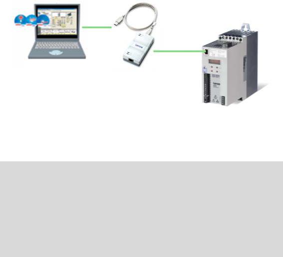
•The USB diagnostic adapter, for instance, can be used for the communication between the PC (including the L-force »Engineer« software) and the controller, see illustration. The USB diagnostic adapter is the connection between the PC (free USB port) and the controller (diagnostic interface).
•For fieldbus communication, the 8400 BaseLine C controller is provided with a CANopen interface.
12 |
Lenze · 8400 BaseLine C · Reference manual · DMS 1.6 EN · 01/2014 · TD05 |
2 Introduction: Parameterising the controller
2.1General notes on parameters
_ _ _ _ _ _ _ _ _ _ _ _ _ _ _ _ _ _ _ _ _ _ _ _ _ _ _ _ _ _ _ _ _ _ _ _ _ _ _ _ _ _ _ _ _ _ _ _ _ _ _ _ _ _ _ _ _ _ _ _ _ _ _ _
2.1General notes on parameters
All parameters for controller parameterising or monitoring are saved as so-called "codes".
•The codes are numbered and designated by a "C" in front of the code, e.g. "C002" in the documentation and the keypad display.
•In addition, every code has a name and specific attributes:
•Access type (read, write)
•Data type
•Limit values
•Lenze setting (factory-set scaling)
•For the sake of clarity, some codes contain "subcodes" for saving parameters.
•This manual uses a slash "/" as a separator between code and subcode (e.g. "C115/1").
•In the keypad display, the subcodes are designated by a small "c", e.g. "c001".
•According to their functionality, the parameters are divided into three groups:
Parameter group |
Examples |
Setting parameters |
C007: Selection of control mode |
Parameters for specifying setpoints and for setting device / |
C012: Acceleration time - main setpoint |
monitoring functions. |
C039: Fixed setpoints |
Configuration parameters |
C620: System connection list: 16-bit |
Parameters for configuring signal connections within the de- |
C621: System connection list: Bool |
vice, e.g. assignment of the digital input terminals to the |
C700: LA_NCtrl: Analog connection list |
control inputs of the application. |
C701: LA_NCtrl: Digital connection list |
Diagnostic/Display parameters |
C052: Motor voltage |
Parameters for displaying device-internal process factors, |
C137: Device status |
current actual values, and status messages, e.g. for diag- |
C150: Status word |
nostic purposes. These are read-only parameters. |
C165: Error info |
|
|
Tip!
The terms "code" and "subcode" generally correspond to the terms "index" and "subindex" and "parameter" and "subparameter".
Lenze · 8400 BaseLine C · Reference manual · DMS 1.6 EN · 01/2014 · TD05 |
13 |
2 Introduction: Parameterising the controller
2.2Handling the memory module
_ _ _ _ _ _ _ _ _ _ _ _ _ _ _ _ _ _ _ _ _ _ _ _ _ _ _ _ _ _ _ _ _ _ _ _ _ _ _ _ _ _ _ _ _ _ _ _ _ _ _ _ _ _ _ _ _ _ _ _ _ _ _ _
2.2Handling the memory module
Danger!
After power-off, wait at least three minutes before working on the controller. When removing the memory module, ensure that the controller is deenergised.
If the memory module has been removed and the device is switched on, the connector pins are live and thus dangerous since the protection against contact is missing.
All parameters of the drive system are saved non-volatilely in the memory module of the controller. This includes the parameters of the controller and parameters relevant for communication.
The plug-in version is especially suited for
•restoring an application after replacing a device.
•duplicating identical drive tasks within the 8400 BaseLine frequency inverter series, e.g. by using the optionally available EPM Programmer.
Note!
•When the device is switched on, all parameters are automatically loaded from the memory module to the main memory of the controller.
•The 8400 BaseLine and 8400 motec controllers use the same (grey) memory module. The memory module can be shifted between these controllers but the controller must be reparameterised afterwards.
•The memory module is not compatible with the memory modules of the 8400 StateLine and 8400 HighLine controllers.
•If the memory module has been removed, the "PS01" error message appears.
When handling the memory module, a distinction is drawn between the following scenarios:
Delivery status
•The memory module is plugged into the EPM slot at the front of the controller.
•The Lenze setting of the parameters is stored in the memory module.
•The memory module can be preconfigured with customerspecific data.
•The memory module is available as a spare part - without any data.
14 |
Lenze · 8400 BaseLine C · Reference manual · DMS 1.6 EN · 01/2014 · TD05 |

2 Introduction: Parameterising the controller
2.2Handling the memory module
_ _ _ _ _ _ _ _ _ _ _ _ _ _ _ _ _ _ _ _ _ _ _ _ _ _ _ _ _ _ _ _ _ _ _ _ _ _ _ _ _ _ _ _ _ _ _ _ _ _ _ _ _ _ _ _ _ _ _ _ _ _ _ _
During operation
Stop!
The memory module must not be plugged in or unplugged during operation.
•The memory module (EPM) is required for operation.
•Full functionality of the memory module is even provided if the power supply has been switched off and only the electronic components of the controller are externally supplied by a 24 V DC voltage, e.g. via the X4/24E terminal.
•Parameter settings can be saved manually.
•Parameter settings can be loaded manually.
•Parameter changes can be saved automatically.
Replacing the controller
•In the event of a device replacement, the entire parameter data of an axis can be copied to the replacement device by "taking along" the memory module, so that additional PC or diagnosis terminal operations are not required.
•When replacing the controller, the versions of the old device and the new device are of importance. Before data are actually transferred, the versions are internally checked. Basically, the following applies:
•Parameter sets of old devices with V 1.0 can be processed on new devices ≥ V 1.0 (downward compatibility).
•Parameters of devices with higher versions are not supported on devices with lower versions. An error message (PS02/PS03) occurs if the parameter set versions of the two devices are not compatible.
Saving the parameters in the memory module safe against mains failure
Controller parameter changes via the »Engineer«, the integrated keypad, or a master control via fieldbus communication will be lost after mains switching of the controller unless the settings have been explicitly saved.
You have various opportunities to prevent a data loss by saving the parameter settings in the memory module:
•Quick saving of all parameters at the push of a button ( 23)
•Automatic saving of parameter changes ( 49)
•Manual saving of parameter settings ( 49)
Lenze · 8400 BaseLine C · Reference manual · DMS 1.6 EN · 01/2014 · TD05 |
15 |

2 Introduction: Parameterising the controller
2.2Handling the memory module
_ _ _ _ _ _ _ _ _ _ _ _ _ _ _ _ _ _ _ _ _ _ _ _ _ _ _ _ _ _ _ _ _ _ _ _ _ _ _ _ _ _ _ _ _ _ _ _ _ _ _ _ _ _ _ _ _ _ _ _ _ _ _ _
Parameter set transfer using the »Engineer«
When an online connection to the controller has been established, the following transfer functions can directly be executed via the Toolbar or the Online menu using the L-force »Engineer«:
Symbol |
Menu command |
Shortcut |
|
Download parameter set |
<F5> |
|
|
|
|
Read parameter set from device |
<F7> |
|
|
|
|
Save parameter set |
|
|
|
|
Tip!
Detailed information on parameter set transfers using the »Engineer« can be found in the »Engineer« online help.
16 |
Lenze · 8400 BaseLine C · Reference manual · DMS 1.6 EN · 01/2014 · TD05 |
2 Introduction: Parameterising the controller
2.3Internal Keypad
_ _ _ _ _ _ _ _ _ _ _ _ _ _ _ _ _ _ _ _ _ _ _ _ _ _ _ _ _ _ _ _ _ _ _ _ _ _ _ _ _ _ _ _ _ _ _ _ _ _ _ _ _ _ _ _ _ _ _ _ _ _ _ _
2.3Internal Keypad
The controller front is provided with an integrated keypad. Use the keypad for quick and simple parameter setting and for displaying current actual values and device states via the respective display parameters.
Note!
After switching on the controller, the internal keypad performs a quick self-test. All segments of the display flash. After the self-test, the keypad shows "rdy" for a short time and then changes to the display of the setpoint speed of the motor. The keypad is now ready for operation.
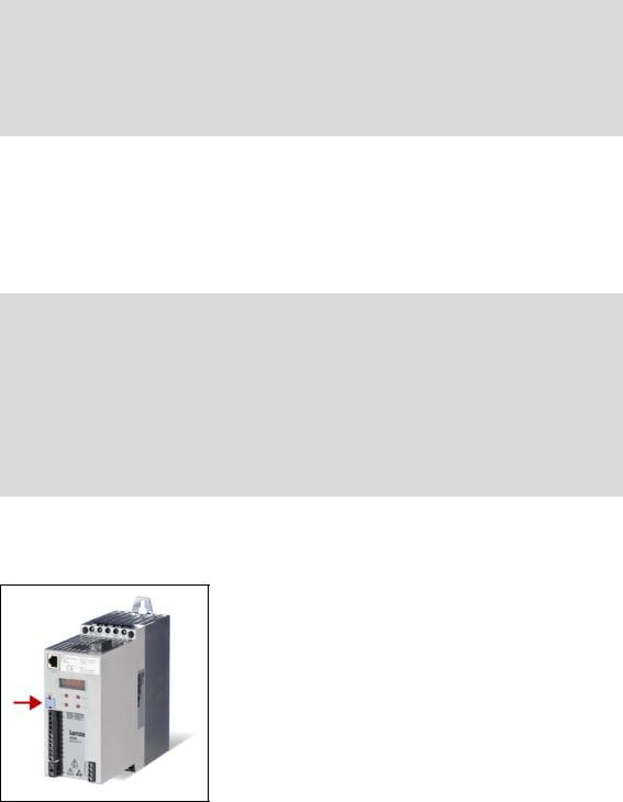
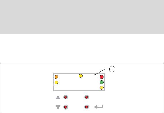
2.3.1Display elements and control panel
Important status information of the controller is displayed optically by LEDs. The positions of the coloured LEDs are marked on the housing by letters.
|
C |
1 |
A |
8888 |
D |
B |
E |
|
|
|
F |
|
ESC |
|
Symbol |
Information |
Meaning |
|
4-character display with LEDs (A ... F) |
|
A |
orange |
Set current/torque limit is reached |
B |
yellow |
Minus sign for identifying the negative numbers bigger than 4 characters |
|
|
when the rotational direction has been reversed. |
C |
yellow |
User LED |
|
|
• configurable via C621/42 |
|
|
• user-defined LED status |
D |
red |
DRIVE ERROR / DRIVE READY |
E |
green |
LED status display ( 18) |
F |
yellow |
Direction of rotation: CCW rotation |
|
|
|
|
Off |
Direction of rotation: CW rotation |
|
|
|
|
blinking |
Commanded direction is not equal to actual direction (e.g. during reversing) |
|
|
|
Lenze · 8400 BaseLine C · Reference manual · DMS 1.6 EN · 01/2014 · TD05 |
17 |
2 Introduction: Parameterising the controller
2.3Internal Keypad
_ _ _ _ _ _ _ _ _ _ _ _ _ _ _ _ _ _ _ _ _ _ _ _ _ _ _ _ _ _ _ _ _ _ _ _ _ _ _ _ _ _ _ _ _ _ _ _ _ _ _ _ _ _ _ _ _ _ _ _ _ _ _ _
Control elements
Key |
Name |
Function |
ESC |
Escape key |
On menu and parameter level: Back |
|
|
In case of parameter processing: Abort (discard changed setting) |
|
Enter key |
On menu and parameter level: Next (confirm selection) |
|
|
In case of parameter processing: OK (accept changed setting) |
|
|
Long pressing (3 seconds): Saving of all parameters |
|
|
Quick saving of all parameters at the push of a button ( 23) |
|
Navigation key |
On menu and parameter level: Navigation |
|
upwards |
In case of parameter processing: Set parameter value |
|
Navigation key |
Long pressing (> 2 seconds): Quick scroll function |
|
||
|
downwards |
|
|
|
|
2.3.2LED status display
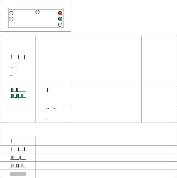
|
C |
|
A |
8888 |
D |
B |
E |
|
|
|
F |
Information on some operating states can quickly be obtained via the front D and E LEDs:
The meaning can be seen from the table below.
|
|
E |
D |
Description |
Device state |
||||
"DRIVE READY" |
"DRIVE ERROR" |
|
(Display in C137) |
||||||
|
OFF |
OFF |
OFF or initialisation active |
Init |
|||||
|
|
|
|
|
|
|
|
|
|
|
|
|
|
|
|
|
OFF |
Safe torque off is active |
SafeTorqueOff |
|
|
|
|
|
|
|
|||
|
|
|
|
|
|
|
|
|
|
|
|
|
|
|
|
|
OFF |
Device is ready to start |
ReadyToSwitchON |
|
|
|
|
|
|
|
|||
|
|
|
|
|
|
|
|
|
|
|
|
|
|
|
|
|
|
|
|
|
|
|
|
|
|
|
OFF |
Device is switched on |
SwitchedON |
|
|
|
|
|
|
|
|||
|
|
|
|
|
|
|
|
|
|
|
|
|
|
|
|
|
|
|
|
|
|
|
|
|
|
|
OFF |
Motor data identification/operation |
OperationEnabled |
|
|
|
|
|
|
|
|||
|
|
|
|
|
|
|
|
|
|
The controller is ready to switch on, switched on or the operation is enabled and a warning is indicated.
|
|
|
|
|
|
|
|
|
|
|
OFF |
|
|
|
|
|
|
Trouble is active |
Trouble |
|
|
|
|
|
|||||
|
|
|
|
|
|
|
|
|
|
|
|
|
|
|
|
|
|
|
|
|
OFF |
|
|
|
|
|
|
Fault is active |
Fault |
|
|
|
|
|
|
|
|||
|
|
|
|
|
|
|
|
|
|
Legend
The symbols used for indicating the LED states have the following meaning:
LED is flashing once approx. every 3 seconds (slow flash)
LED is flashing once approx. every 1.25 seconds (flash)
LED is flashing twice approx. every 1.25 seconds (double flash)
LED is blinking every second
LED is permanently on
18 |
Lenze · 8400 BaseLine C · Reference manual · DMS 1.6 EN · 01/2014 · TD05 |
2 Introduction: Parameterising the controller
2.3Internal Keypad
_ _ _ _ _ _ _ _ _ _ _ _ _ _ _ _ _ _ _ _ _ _ _ _ _ _ _ _ _ _ _ _ _ _ _ _ _ _ _ _ _ _ _ _ _ _ _ _ _ _ _ _ _ _ _ _ _ _ _ _ _ _ _ _
2.3.3Display messages
Display |
|
Meaning |
An01 |
constant |
Analog input 1: Current < 4 mA |
bF |
blinking |
Identification error. |
|
|
• Drive ID stored in EMP does not match the drive ID stored in the |
|
|
controller. |
br |
flashes during the hold time |
DC braking is executed. |
|
of DC braking |
|
CA06 |
constant |
CAN CRC error |
CA07 |
constant |
CAN Bus Warn |
CA08 |
constant |
CAN Bus Stopped |
CA0b |
constant |
CAN Bus Live Time |
CA0F |
constant |
CAN: Bit 14 ("SetFail") in the control word is set. |
CAL |
blinking |
Identification is executed. |
|
|
The operation is not yet enabled. |
CAL / Err |
alternatively blinking |
Identification is not ready to start. |
|
|
• C088, C089 or C090 is 0. |
CAL / Stop |
alternatively blinking |
Identification is ready to start. |
CE1 |
constant |
CAN: Time monitoring for RPDO1 has tripped. |
CE2 |
constant |
CAN: Time monitoring for RPDO2 has tripped. |
CE4 |
constant |
CAN Bus Off |
CL |
constant |
Clamp: The current limit value selected in C022 has been reached. |
dec |
constant |
Deceleration is temporarily suspended because of higher bus volta- |
|
|
ge |
dF01 ... dF10 |
constant |
Internal error |
dH69 |
constant |
Adjustment data error |
Err |
blinking |
A wrong password has been entered. |
FCL |
constant |
The current limit value selected in C022 has been exceeded. |
FSt |
constant |
"Flying restart" function is executed. |
ID1 |
constant |
Motor data identification error |
LU |
constant |
DC bus undervoltage |
OC1 |
constant |
Power section - short circuit |
OC12 |
constant |
I2xt brake resistor overload |
OC2 |
constant |
Power section - earth fault |
OC5 |
constant |
Ixt overload |
OC6 |
constant |
I2xt motor overload |
OC9 |
constant |
Ixt overload - shutdown limit |
OH |
constant |
Heatsink overtemperature |
OU |
constant |
DC bus overvoltage |
PASS |
0.5 seconds on |
Password protection is active |
PS01 |
constant |
No memory module inserted |
PS02 |
constant |
Parameter set is invalid |
PS03 |
constant |
Parameter set device invalid |
PS31 |
constant |
Incompatible or unknown HW components have been found. |
Su02 |
constant |
One mains phase is missing |
|
|
|
Lenze · 8400 BaseLine C · Reference manual · DMS 1.6 EN · 01/2014 · TD05 |
19 |

2 Introduction: Parameterising the controller
2.3Internal Keypad
_ _ _ _ _ _ _ _ _ _ _ _ _ _ _ _ _ _ _ _ _ _ _ _ _ _ _ _ _ _ _ _ _ _ _ _ _ _ _ _ _ _ _ _ _ _ _ _ _ _ _ _ _ _ _ _ _ _ _ _ _ _ _ _
Display |
|
Meaning |
US01 |
constant |
User error 1 |
US02 |
constant |
User error 2 |
|
|
|
Detailed information on diagnostics using the »Engineer« and a description of possible error messages can be found in the chapter entitled "Diagnostics & error management".
( 145)
20 |
Lenze · 8400 BaseLine C · Reference manual · DMS 1.6 EN · 01/2014 · TD05 |

2 Introduction: Parameterising the controller
2.3Internal Keypad
_ _ _ _ _ _ _ _ _ _ _ _ _ _ _ _ _ _ _ _ _ _ _ _ _ _ _ _ _ _ _ _ _ _ _ _ _ _ _ _ _ _ _ _ _ _ _ _ _ _ _ _ _ _ _ _ _ _ _ _ _ _ _ _
2.3.4Menu structure
6WDWH |
3DVVZRUG |
0HQX |
&RGH |
6XEFRGH |
9DOXH |
|
|
|
|
|
|
ģĤ; |
|
(6& |
(6& |
|
(6& |
|
|
|
|||
MM |
|
|
% |
|
|
|
2#55 |
|
|
ĥ |
|
|
(6& |
Ħ |
% |
(6& |
(6& |
|
|
|
|
ĥ |
|
|
|
|
|
|
|
|
|
|
|
|
|
|
|
|
|
|
|
|
|
|
|
|
|
•Without active password protection, the "password" level will be skipped.
•The following applies when changing between the levels "Menu", "Code" and "Subcode": The keypad records the last selection.
•For codes without subcodes, the "Subcode" level will be skipped.
Menu Info
-0- |
Access to the parameters of the user menu. |
•The user menu of a device serves to create a selection of frequently used parameters to be able to access and change these parameters quickly. User menu ( 22)
-1- |
Access to all drive parameters. |
|
|
-2- |
Access to parameters for quick commissioning with terminal control. |
|
|
-3- |
Access to parameters for quick commissioning with the integrated keypad. |
|
|
-4- |
Access to motor control parameters. |
|
|
-5- |
Access to diagnostic/display parameters. |
Note!
When the password protection is activated and no password or a wrong password is entered, only the parameters of the user menu can be accessed using the integrated keypad. All other menus/parameters require the correct password.
Password protection ( 23)
Lenze · 8400 BaseLine C · Reference manual · DMS 1.6 EN · 01/2014 · TD05 |
21 |

2 Introduction: Parameterising the controller
2.3Internal Keypad
_ _ _ _ _ _ _ _ _ _ _ _ _ _ _ _ _ _ _ _ _ _ _ _ _ _ _ _ _ _ _ _ _ _ _ _ _ _ _ _ _ _ _ _ _ _ _ _ _ _ _ _ _ _ _ _ _ _ _ _ _ _ _ _
2.3.5User menu
The user menu (menu -0-) contains a selection of frequently used parameters to be able to access and change these parameters quickly.
•The integrated keypad serves to change the preset parameter selection in C517: Enter the codes the user menu is to contain into the subcodes c001 ...c020. When "0" is set, no entry is displayed in the user menu.
•The »Engineer« serves to configure the user menu on the User menu tab of the controller. Here, additional functions are available for loading and saving the parameter selection.
The user menu contains the following parameters:
Code |
Subcode |
Info |
Lenze setting |
|
|
|
|
Value |
Unit |
C051 |
- |
Display of actual speed value |
- |
rpm |
C053 |
- |
Display of DC-bus voltage |
- |
V |
C054 |
- |
Display of motor current |
- |
A |
C061 |
- |
Display of heatsink temperature |
- |
°C |
C137 |
- |
Display of device status |
|
- |
C011 |
- |
Reference speed |
1500 |
rpm |
|
|
|
|
|
C039 |
c001 |
Fixed setpoint 1 |
40.0 |
% |
|
|
|
|
|
|
c002 |
Fixed setpoint 2 |
60.0 |
% |
|
|
|
|
|
|
c003 |
Fixed setpoint 3 |
80.0 |
% |
|
|
|
|
|
C012 |
- |
Acceleration time - main setpoint |
2.0 |
s |
|
|
|
|
|
C013 |
- |
Deceleration time - main setpoint |
2.0 |
s |
|
|
|
|
|
C015 |
- |
V/f base frequency |
50.0 |
Hz |
|
|
|
|
|
C016 |
- |
Vmin boost |
0.0 |
% |
|
|
|
|
|
C022 |
- |
Imax in motor mode |
47.00 |
A |
|
|
|
|
|
C120 |
- |
Motor overload threshold (I2xt) |
100 |
% |
C087 |
- |
Rated motor speed |
1460 |
rpm |
|
|
|
|
|
C099 |
- |
Display of firmware version |
|
- |
|
|
|
|
|
Highlighted in grey = display parameter
Note!
If the password protection is activated and no password or a wrong password is entered, only these parameters can be accessed with the integrated keypad.
Password protection ( 23)
22 |
Lenze · 8400 BaseLine C · Reference manual · DMS 1.6 EN · 01/2014 · TD05 |

2 Introduction: Parameterising the controller
2.3Internal Keypad
_ _ _ _ _ _ _ _ _ _ _ _ _ _ _ _ _ _ _ _ _ _ _ _ _ _ _ _ _ _ _ _ _ _ _ _ _ _ _ _ _ _ _ _ _ _ _ _ _ _ _ _ _ _ _ _ _ _ _ _ _ _ _ _
2.3.6Quick saving of all parameters at the push of a button
Keep the entry button pressed for 3 seconds to save all parameter settings safe against mains failure.
|
C |
|
A |
SAVE |
D |
B |
E |
|
|
|
F |
|
ESC |
|
|
3 sec |
|
•During the saving process, "SAVE" is blinking in the display.
•After approximately 2 seconds, "SAVE" will disappear from the display and you can continue your work.
Related topics:
Save parameter settings ( 49)
2.3.7Password protection
The controller offers the option to protect the unauthorised access to the menu level by assigning a password. The following sections describe how to create, change, or delete the password protection and how to access the menu level via the password.
Enter password and confirm it
Carry out the steps if you want to create the password protection for the first time for e.g. a controller in default status:
Step |
|
Info |
1. |
Mains on |
After the mains has been switched on and the keypad self test has been completed, |
|
|
"00" is displayed |
2. |
|
After pressing the enter key: |
|
|
Without password protection you have free access from here to all menus (and thus |
|
|
all parameters). |
3. |
|
Select menu -1- (all parameters). |
4. |
|
Confirm selection. |
5. |
|
Select code C094 ("password"). |
6. |
|
Confirm selection. |
|
|
("00" is now blinking, i.e. entry is possible.) |
7. |
|
Set the desired password ("01" ... "9999"). |
8. |
|
Accept password. |
9. |
(3 seconds) |
Keep the entry button pressed for 3 seconds in order to save the parameter settings |
|
|
safe against mains failure. |
|
|
|
Lenze · 8400 BaseLine C · Reference manual · DMS 1.6 EN · 01/2014 · TD05 |
23 |
2 Introduction: Parameterising the controller
2.3Internal Keypad
_ _ _ _ _ _ _ _ _ _ _ _ _ _ _ _ _ _ _ _ _ _ _ _ _ _ _ _ _ _ _ _ _ _ _ _ _ _ _ _ _ _ _ _ _ _ _ _ _ _ _ _ _ _ _ _ _ _ _ _ _ _ _ _
Change the existing password or deactivate the password protection
Step |
|
Info |
1. |
Mains on |
After the mains has been switched on and the keypad self test has been completed, |
|
|
"00" is displayed |
2. |
|
After pressing the enter key and with existing password protection: |
|
|
"PASS" is displayed for a short time, then "0000". |
3. |
|
Enter password. |
4. |
|
Confirm entry. |
5. |
|
Select menu -1- (all parameters). |
6. |
|
Confirm selection. |
7. |
|
Select code C094 ("password"). |
8. |
|
Confirm selection. |
|
|
(The existing password is now blinking, i.e. a change is possible.) |
9. |
|
Change password: Set new password ("01" ... "9999"). |
|
|
Deactivate password protection: Set "00". |
10. |
|
Accept setting. |
11. |
(3 seconds) |
Keep the entry button pressed for 3 seconds in order to save the parameter settings |
|
|
safe against mains failure. |
|
|
|
Access password-protected controller without knowing the password
When the password protection is activated and no password or a wrong password is entered, only the max. 20 parameters of the user menu can be accessed.
Step |
|
Info |
1. |
Mains on |
After the mains has been switched on and the keypad self test has been completed, |
|
|
"00" is displayed |
2. |
|
After pressing the enter key and with existing password protection: |
|
|
"PASS" is displayed for a short time, then "0000". |
3. |
|
After direct confirmation of the value "0000": |
|
or |
• Only the parameters of the user menu can be selected. |
|
|
When the wrong password has been entered and confirmed: |
|
|
• "Err" is displayed for a short time, then only the parameters of the User menu can |
|
|
be selected. |
Reach password-protected menu level with knowing the password |
||
Step |
|
Info |
1. |
Mains on |
After the mains has been switched on and the keypad self test has been completed, |
|
|
"00" is displayed |
2. |
|
After pressing the enter key and with existing password protection: |
|
|
"PASS" is displayed for a short time, then "0000". |
3. |
|
Enter password. |
4. |
|
When the correct password has been confirmed: |
|
|
You have free access from here to all menus (and thus all parameters). |
|
|
|
24 |
Lenze · 8400 BaseLine C · Reference manual · DMS 1.6 EN · 01/2014 · TD05 |

3 Commissioning
3.1Safety instructions with regard to commissioning
_ _ _ _ _ _ _ _ _ _ _ _ _ _ _ _ _ _ _ _ _ _ _ _ _ _ _ _ _ _ _ _ _ _ _ _ _ _ _ _ _ _ _ _ _ _ _ _ _ _ _ _ _ _ _ _ _ _ _ _ _ _ _ _
3 Commissioning
The 8400 BaseLine C controller is commissioned in one of the following ways:
•Commissioning with integrated keypad
•If only a few parameters have to be adapted.
•For test/demonstration purposes.
•Commissioning with PC/»Engineer«
•The »Engineer« provides a comfortable access to all parameters of the 8400 BaseLine C controller and hence full flexibility in the commissioning process.
3.1Safety instructions with regard to commissioning
General safety instructions
In order to prevent injury to persons or damage to material assets
•before connecting the mains voltage, check
•The wiring for completeness, short circuit, and earth fault
•The "emergency stop" function of the entire system
•The motor circuit configuration (star/delta) must be adapted to the output voltage of the controller
•The in-phase connection of the motor
•Check the setting of the most important drive parameters before enabling the controller:
•The V/f rated frequency must be adapted to the motor circuit configuration!
•The drive parameters relevant for your application must be set correctly!
•The configuration of the I/O terminals must be adapted to the wiring!
•Make sure that no speed setpoint is applied before controller enable.
Safety instructions with regard to motor operation
Danger!
•For thermal reasons, continuous operation of self-ventilated motors at a low field frequency and rated motor current is not permissible!
•If required, activate the Brake resistor monitoring (I2xt). ( 106)
•With regard to the V/f base frequency (C015), observe the following difference to the controllers 8400 StateLine/HighLine/TopLine:
For the 8400 BaseLine, the reference voltage for the V/f base frequency is the rated motor voltage (C090) according to motor nameplate (independent of the mains voltage on the supply side).
Lenze · 8400 BaseLine C · Reference manual · DMS 1.6 EN · 01/2014 · TD05 |
25 |
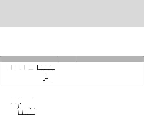
3 Commissioning
3.2Preparing the 8400 BaseLine for commissioning
_ _ _ _ _ _ _ _ _ _ _ _ _ _ _ _ _ _ _ _ _ _ _ _ _ _ _ _ _ _ _ _ _ _ _ _ _ _ _ _ _ _ _ _ _ _ _ _ _ _ _ _ _ _ _ _ _ _ _ _ _ _ _ _
3.2Preparing the 8400 BaseLine for commissioning
Danger!
Take all the necessary safety precautions before you carry out the following commissioning steps and switch the device on!
Safety instructions with regard to commissioning ( 25)
1.Wiring the power connections
•Refer to the mounting instructions supplied with the drive controller to find help on how to correctly design the power connections to match the requirements of your device.
2.Wire the control connections
•The following shows the wiring for the Lenze setting.
Analog input at X4 |
|
|
|
|
|
Terminal |
Function |
|
|
|
|
|
|
A1U |
Setpoint selection |
X4 DO1 24E DI4 DI3 |
DI2 |
DI1 |
RFR |
12I |
AR |
A1U GND |
• Scaling: 10 V ≡ 100 % ≡ 1500 rpm |
|
|
|
|
|
|
|
|
|
|
|
|
|
|
|
(for 4-pole motor) |
|
|
|
|
1k |
|
|
|
|
|
|
|
|
|
|
|
|
|
|
|
10k |
|
0 10V |
|
Digital inputs at X4 |
|
|
|
|
Terminal |
Function |
||||||||||||||
X4 |
|
|
|
|
|
|
|
|
|
|
|
|
|
|
|
|
|
RFR |
Controller enable: HIGH level |
|
DO1 |
24E |
DI4 |
DI3 |
DI2 |
DI1 |
RFR |
12I |
AR |
A1U |
GND |
|
|
Error reset: HIGH-LOW edge |
|||||||
|
|
|
|
|
|
|
|
|
|
|
|
|
|
|
|
|
|
|
|
|
|
|
|
|
|
|
|
|
|
|
|
|
|
|
|
|
|
|
|
DI1 |
Selection fixed setpoint 1 ... 3 |
|
|
|
|
|
|
|
|
|
|
|
|
|
|
|
|
|
|
|
|
|
|
|
|
|
|
|
|
|
|
|
|
|
|
|
|
|
|
|
|
DI2 |
|
|
|
|
|
|
|
|
|
|
|
|
|
|
|
|
|
|
|
|
|
|
DI1 ... DI4: All HIGH active |
|
|
|
|
DI3 |
Request DC-injection braking (DCB) |
||||||||||||||
|
|
|
|
|
|
|||||||||||||||
|
|
|
|
DI4 |
Request change of direction of rotation |
|||||||||||||||
|
|
|
|
|
|
|
|
|
|
|
|
|
|
|
|
|
|
|
||
|
|
|
|
|
|
|
|
|
|
|
|
|
|
|
|
|
|
|
|
|
3.Inhibit the controller:
Set terminal X4/RFR to LOW level or open contact to terminal X4/12I .
4.Switch on voltage supply of the controller.
•Information on some operating states can be quickly obtained via the LED display of the integrated keypad. LED status display ( 18)
When the green LED is blinking and the red LED is off, the controller is ready to start and you can continue with commissioning as required:
Commissioning with integrated keypad ( 27) or
Commissioning with the »Engineer« ( 31)
26 |
Lenze · 8400 BaseLine C · Reference manual · DMS 1.6 EN · 01/2014 · TD05 |

3 Commissioning
3.3Commissioning with integrated keypad
_ _ _ _ _ _ _ _ _ _ _ _ _ _ _ _ _ _ _ _ _ _ _ _ _ _ _ _ _ _ _ _ _ _ _ _ _ _ _ _ _ _ _ _ _ _ _ _ _ _ _ _ _ _ _ _ _ _ _ _ _ _ _ _
3.3Commissioning with integrated keypad
Only a few parameters need to be adapted for the drive. Afterwards, the drive application can be immediately controlled via the digital and analog inputs of the controller in the preset control mode "Terminals 0".
Information on how to use the integrated keypad can be found in the chapter entitled "Internal Keypad". ( 17)
Commissioning steps
In the following, commissioning of the controller using the integrated keypad is described step by step. Please process the chapters consecutively and execute all steps carefully. This procedure will help you to commission the controller quickly and as safe as possible:
Load Lenze setting
Parameterise drive/application ( 28)
Save parameter settings safe against mains failure ( 29)Enable controller and select speed ( 30)
3.3.1Load Lenze setting
In order to achieve a defined device configuration, it is advisable to make sure that the device is in its original delivery state. For this purpose, the "Load Lenze setting" device command is available.
Step |
|
Info |
1. |
Mains on |
After the mains has been switched on and the keypad self test has been completed, |
|
|
"00" is displayed |
2. |
|
After pressing the enter key: |
|
|
Without password protection you have free access from here to all menus (and thus |
|
|
all parameters). |
3. |
|
Select menu -2-. |
|
|
• The menu -2- contains parameters for quick commissioning with terminal cont- |
|
|
rol. |
4. |
|
Confirm selection. |
5. |
|
Confirm first code C002 ("device commands") of the menu -2-. |
6. |
|
Confirm subcode c001 ("load Lenze setting"). |
7. |
|
Set value "01" (≡ "Start"). |
8. |
|
Accept parameter setting to execute the "Load Lenze setting" device command. |
|
|
|
Lenze · 8400 BaseLine C · Reference manual · DMS 1.6 EN · 01/2014 · TD05 |
27 |
3 Commissioning
3.3Commissioning with integrated keypad
_ _ _ _ _ _ _ _ _ _ _ _ _ _ _ _ _ _ _ _ _ _ _ _ _ _ _ _ _ _ _ _ _ _ _ _ _ _ _ _ _ _ _ _ _ _ _ _ _ _ _ _ _ _ _ _ _ _ _ _ _ _ _ _
3.3.2Parameterise drive/application
The menu -2- of the integrated keypad contains all basic parameters to commission the drive/application "actuating drive speed" quickly and easily for a terminal control. When you set these parameters to suitable and sensible values, the controller can be operated properly.
Parameter |
Lenze setting |
Info |
||
|
Value |
Unit |
|
|
C002/1 |
0: Off / ready |
Reset all parameters to the Lenze setting which are sa- |
||
Load Lenze setting |
|
|
ved in the controller firmware. |
|
C007 |
10: Terminals 0 |
Terminal assignment of the control modes ( 139) |
||
Select control mode |
|
|
|
|
C011 |
1500 |
rpm |
All speed setpoint selections are provided in % and al- |
|
Reference speed |
|
|
ways refer to the reference speed set in C011. |
|
|
|
|
The motor reference speed is given on the motor name- |
|
|
|
|
plate. |
|
C012 |
2.0 |
s |
The setpoint is led via a ramp function generator with li- |
|
Acceleration time - main setpoint |
|
|
near characteristic. The ramp function generator con- |
|
|
|
|
verts setpoint step-changes at the input into a ramp. |
|
C013 |
2.0 |
s |
||
L_NSet_1 ( 309) |
||||
Deceleration time - main setpoint |
|
|
||
C015 |
50.0 |
Hz |
Adapting the V/f base frequency ( 83) |
|
V/f base frequency |
|
|
|
|
C016 |
0.0 |
% |
Adapting the Vmin boost ( 84) |
|
Vmin boost |
|
|
|
|
C022 |
47.00 |
A |
Optimising the Imax controller ( 85) |
|
Current limit (in motor mode) |
|
|
|
|
C087 |
1460 |
rpm |
Motor selection/Motor data ( 65) |
|
Rated motor speed |
|
|
|
|
C089 |
50 |
Hz |
|
|
Rated motor frequency |
|
|
|
|
C039/1 |
40.0 |
% |
A fixed setpoint for the setpoint generator can be acti- |
|
Fixed setpoint 1 |
|
|
vated instead of the main setpoint via the digital inputs |
|
|
|
|
DI1 and DI2. |
|
C039/2 |
60.0 |
% |
||
• The fixed setpoints are selected in [%] based on the |
||||
Fixed setpoint 2 |
|
|
||
|
|
reference speed (C011). |
||
|
|
|
||
C039/3 |
80.0 |
% |
L_NSet_1 ( 309) |
|
Fixed setpoint 3 |
|
|
|
|
C051 |
- |
rpm |
|
|
Actual speed value |
|
|
|
|
C054 |
- |
A |
|
|
Current motor current |
|
|
|
|
Highlighted in grey = display parameter |
|
|
|
|
|
|
|
|
|
More detailed information on the drive application:
Drive application ( 121)Interface description ( 127)
Setting parameters (short overview) ( 132)Pre-assignment of the drive application ( 133)Terminal assignment of the control modes ( 139)
28 |
Lenze · 8400 BaseLine C · Reference manual · DMS 1.6 EN · 01/2014 · TD05 |
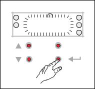
3 Commissioning
3.3Commissioning with integrated keypad
_ _ _ _ _ _ _ _ _ _ _ _ _ _ _ _ _ _ _ _ _ _ _ _ _ _ _ _ _ _ _ _ _ _ _ _ _ _ _ _ _ _ _ _ _ _ _ _ _ _ _ _ _ _ _ _ _ _ _ _ _ _ _ _
3.3.3Save parameter settings safe against mains failure
If parameter settings are changed in the controller, those changes will be lost after mains switching of the controller unless the settings have been saved explicitly.
|
C |
|
A |
SAVE |
D |
B |
E |
|
|
|
F |
|
ESC |
|
|
3 sec |
|
•Keep the entry button pressed for 3 seconds in order to save the parameter settings safe against mains failure.
Tip!
In C141, an automatic saving can be activated.Automatic saving of parameter changes ( 49)
Lenze · 8400 BaseLine C · Reference manual · DMS 1.6 EN · 01/2014 · TD05 |
29 |

3 Commissioning
3.3Commissioning with integrated keypad
_ _ _ _ _ _ _ _ _ _ _ _ _ _ _ _ _ _ _ _ _ _ _ _ _ _ _ _ _ _ _ _ _ _ _ _ _ _ _ _ _ _ _ _ _ _ _ _ _ _ _ _ _ _ _ _ _ _ _ _ _ _ _ _
3.3.4Enable controller and select speed
Note!
If the controller is enabled at power-on and the auto-start option is activated in C142 "Inhibit at power-on" (Lenze setting), the controller remains in the "ReadyToSwitchON" state.
For changing to the "SwitchedON" state, first deactivate the controller enable: Set terminal X4/RFR to LOW level or open contact to terminal X4/12I.
When the controller is in the "SwitchedON" state:
1.Enable controller:
Set terminal X4/RFR to HIGH level or close contact to terminal X4/12I n.
2.Select speed:
•In the "Terminals 0" by selecting a voltage at the analog input or by selecting a fixed setpoint via the digital inputs DI1/DI2.
DI1 |
DI2 |
Speed selection |
LOW |
LOW |
The setpoint speed is selected via the analog input 1 |
|
|
• Scaling: 10 V ≡ 100 % ≡ reference speed (C011) |
HIGH |
LOW |
The fixed setpoint 1 (C039/1) is used as setpoint speed. |
|
|
• Lenze setting: 40 % of the reference speed (C011) |
LOW |
HIGH |
The fixed setpoint 2 (C039/2) is used as setpoint speed. |
|
|
• Lenze setting: 60 % of the reference speed (C011) |
HIGH |
HIGH |
The fixed setpoint 3 (C039/3) is used as setpoint speed. |
|
|
• Lenze setting: 80 % of the reference speed (C011) |
|
|
|
Note!
Observe the actual speed value (display in C051) as well as the LED status display and Display messages indicated in the integrated keypad.
Tip!
More control functions in the "Terminals 0" control mode:
•DI3: HIGH level ≡ request DC-injection braking
•DI4: HIGH level ≡ request change of direction of rotation
30 |
Lenze · 8400 BaseLine C · Reference manual · DMS 1.6 EN · 01/2014 · TD05 |
Loading...