


EDS84DPS424
.M^h
Ä.M^hä
L−force Drives
Hardware Manual
8400 protec 0.75 ... 7.5 kW
E84Dxxxxxxx HighLine/StateLine/EMS
Decentralised frequency inverter
l

Contents i
1 |
About this documentation . . . . . . . . . . . . . . . . . . . . . . . . . . . . . . . . . . . . . . . . . . . . . . . . . . |
7 |
||
|
1.1 |
Document history . . . . . . . . . . . . . . . . . . . . . . . . . . . . . . . . . . . . . . . . . . . . . . . . . . . . |
7 |
|
|
1.2 |
Conventions used . . . . . . . . . . . . . . . . . . . . . . . . . . . . . . . . . . . . . . . . . . . . . . . . . . . . |
8 |
|
|
1.3 |
Terms and abbreviations used . . . . . . . . . . . . . . . . . . . . . . . . . . . . . . . . . . . . . . . . . . |
9 |
|
|
1.4 |
Notes used . . . . . . . . . . . . . . . . . . . . . . . . . . . . . . . . . . . . . . . . . . . . . . . . . . . . . . . . . . |
12 |
|
2 |
Safety instructions . . . . . . . . . . . . . . . . . . . . . . . . . . . . . . . . . . . . . . . . . . . . . . . . . . . . . . . . . |
13 |
||
|
2.1 |
General safety and application notes for Lenze controllers . . . . . . . . . . . . . . . . . . |
13 |
|
|
2.2 |
General safety and application instructions for Lenze motors . . . . . . . . . . . . . . . . |
16 |
|
|
2.3 |
Residual hazards . . . . . . . . . . . . . . . . . . . . . . . . . . . . . . . . . . . . . . . . . . . . . . . . . . . . . |
19 |
|
3 |
Product description . . . . . . . . . . . . . . . . . . . . . . . . . . . . . . . . . . . . . . . . . . . . . . . . . . . . . . . . |
20 |
||
|
3.1 |
Device features . . . . . . . . . . . . . . . . . . . . . . . . . . . . . . . . . . . . . . . . . . . . . . . . . . . . . . |
20 |
|
|
3.2 |
Identification . . . . . . . . . . . . . . . . . . . . . . . . . . . . . . . . . . . . . . . . . . . . . . . . . . . . . . . . |
21 |
|
|
3.3 |
Type code . . . . . . . . . . . . . . . . . . . . . . . . . . . . . . . . . . . . . . . . . . . . . . . . . . . . . . . . . . |
22 |
|
|
3.4 |
Overview of standard devices . . . . . . . . . . . . . . . . . . . . . . . . . . . . . . . . . . . . . . . . . . |
25 |
|
|
3.5 |
Communication . . . . . . . . . . . . . . . . . . . . . . . . . . . . . . . . . . . . . . . . . . . . . . . . . . . . . . |
27 |
|
|
|
3.5.1 |
CAN port . . . . . . . . . . . . . . . . . . . . . . . . . . . . . . . . . . . . . . . . . . . . . . . . . . . . |
27 |
|
|
3.5.2 |
Infrared remote control receiver . . . . . . . . . . . . . . . . . . . . . . . . . . . . . . . . . |
28 |
|
|
3.5.3 |
Extensions in EMS version . . . . . . . . . . . . . . . . . . . . . . . . . . . . . . . . . . . . . . |
28 |
|
|
3.5.4 |
Infrared interface . . . . . . . . . . . . . . . . . . . . . . . . . . . . . . . . . . . . . . . . . . . . . |
29 |
|
3.6 |
Concepts for the mains connection . . . . . . . . . . . . . . . . . . . . . . . . . . . . . . . . . . . . . . |
30 |
|
|
|
3.6.1 |
Concepts for the connection of individual axes . . . . . . . . . . . . . . . . . . . . |
30 |
|
|
3.6.2 |
Concepts for the connection of the power bus . . . . . . . . . . . . . . . . . . . . . |
32 |
|
3.7 |
EMS mains connection concepts . . . . . . . . . . . . . . . . . . . . . . . . . . . . . . . . . . . . . . . . |
35 |
|
|
|
3.7.1 |
Half wave (coded) . . . . . . . . . . . . . . . . . . . . . . . . . . . . . . . . . . . . . . . . . . . . . |
35 |
|
|
3.7.2 |
Power wave . . . . . . . . . . . . . . . . . . . . . . . . . . . . . . . . . . . . . . . . . . . . . . . . . . |
36 |
|
|
3.7.3 |
DECA bus . . . . . . . . . . . . . . . . . . . . . . . . . . . . . . . . . . . . . . . . . . . . . . . . . . . . |
37 |
|
|
3.7.4 |
Inductive . . . . . . . . . . . . . . . . . . . . . . . . . . . . . . . . . . . . . . . . . . . . . . . . . . . . |
38 |
4 |
Technical data |
. . . . . . . . . . . . . . . . . . . . . . . . . . . . . . . . . . . . . . . . . . . . . . . . . . . . . . . . . . . . |
39 |
|
|
4.1 |
General data and operating conditions . . . . . . . . . . . . . . . . . . . . . . . . . . . . . . . . . |
39 |
|
|
4.2 |
Rated data . . . . . . . . . . . . . . . . . . . . . . . . . . . . . . . . . . . . . . . . . . . . . . . . . . . . . . . . . . |
46 |
|
|
|
4.2.1 |
Overview . . . . . . . . . . . . . . . . . . . . . . . . . . . . . . . . . . . . . . . . . . . . . . . . . . . . |
46 |
|
|
4.2.2 |
Operation at rated mains voltage 400 V . . . . . . . . . . . . . . . . . . . . . . . . . . |
48 |
|
|
4.2.3 |
Operation at a rated mains voltage of 500 V . . . . . . . . . . . . . . . . . . . . . . |
51 |
|
4.3 |
Current characteristics . . . . . . . . . . . . . . . . . . . . . . . . . . . . . . . . . . . . . . . . . . . . . . . . |
54 |
|
|
4.4 |
Overcurrent operation . . . . . . . . . . . . . . . . . . . . . . . . . . . . . . . . . . . . . . . . . . . . . . . . |
56 |
|
|
4.5 |
Terminal description . . . . . . . . . . . . . . . . . . . . . . . . . . . . . . . . . . . . . . . . . . . . . . . . . . |
59 |
|
EDS84DPS424 EN 5.0
l 3

i Contents
|
4.6 |
Supply concept of control voltage . . . . . . . . . . . . . . . . . . . . . . . . . . . . . . . . . . . . . . . |
61 |
|
|
|
4.6.1 |
Internal 24 V supply voltage . . . . . . . . . . . . . . . . . . . . . . . . . . . . . . . . . . . . |
61 |
|
|
4.6.2 |
External supply voltage 24 V . . . . . . . . . . . . . . . . . . . . . . . . . . . . . . . . . . . . |
62 |
|
4.7 |
Control terminals . . . . . . . . . . . . . . . . . . . . . . . . . . . . . . . . . . . . . . . . . . . . . . . . . . . . . |
64 |
|
|
|
4.7.1 |
Digital inputs . . . . . . . . . . . . . . . . . . . . . . . . . . . . . . . . . . . . . . . . . . . . . . . . |
64 |
|
|
4.7.2 |
Digital outputs . . . . . . . . . . . . . . . . . . . . . . . . . . . . . . . . . . . . . . . . . . . . . . . |
65 |
|
|
4.7.3 |
Analog inputs . . . . . . . . . . . . . . . . . . . . . . . . . . . . . . . . . . . . . . . . . . . . . . . . |
66 |
|
|
4.7.4 |
Synchronous serial interface (SSI) . . . . . . . . . . . . . . . . . . . . . . . . . . . . . . . . |
66 |
|
|
4.7.5 |
Remote control (IrRC) . . . . . . . . . . . . . . . . . . . . . . . . . . . . . . . . . . . . . . . . . . |
66 |
|
|
4.7.6 |
Interfaces of the EMS version . . . . . . . . . . . . . . . . . . . . . . . . . . . . . . . . . . . |
67 |
|
|
4.7.7 |
Motor holding brake connection . . . . . . . . . . . . . . . . . . . . . . . . . . . . . . . . |
68 |
5 |
Mechanical installation . . . . . . . . . . . . . . . . . . . . . . . . . . . . . . . . . . . . . . . . . . . . . . . . . . . . . |
70 |
||
|
5.1 |
Important notes . . . . . . . . . . . . . . . . . . . . . . . . . . . . . . . . . . . . . . . . . . . . . . . . . . . . . . |
70 |
|
|
5.2 |
Dimensions . . . . . . . . . . . . . . . . . . . . . . . . . . . . . . . . . . . . . . . . . . . . . . . . . . . . . . . . . . |
71 |
|
|
5.3 |
Mounting clearance . . . . . . . . . . . . . . . . . . . . . . . . . . . . . . . . . . . . . . . . . . . . . . . . . . . |
72 |
|
6 |
Electrical installation − HighLine/StateLine version . . . . . . . . . . . . . . . . . . . . . . . . . . . . . . |
73 |
||
|
6.1 |
Important notes . . . . . . . . . . . . . . . . . . . . . . . . . . . . . . . . . . . . . . . . . . . . . . . . . . . . . . |
73 |
|
|
|
6.1.1 |
Electrical isolation . . . . . . . . . . . . . . . . . . . . . . . . . . . . . . . . . . . . . . . . . . . . |
76 |
|
|
6.1.2 |
Device protection . . . . . . . . . . . . . . . . . . . . . . . . . . . . . . . . . . . . . . . . . . . . . |
76 |
|
|
6.1.3 |
Maximum motor cable length . . . . . . . . . . . . . . . . . . . . . . . . . . . . . . . . . . |
77 |
|
|
6.1.4 |
Motor protection . . . . . . . . . . . . . . . . . . . . . . . . . . . . . . . . . . . . . . . . . . . . . |
77 |
|
6.2 |
Safety instructions for the installation according to UL or UR . . . . . . . . . . . . . . . . |
78 |
|
|
6.3 |
Safety instructions for the installation according to UL or UR . . . . . . . . . . . . . . . . |
79 |
|
|
6.4 |
Installation according to EMC (installation of a CE−typical drive system) . . . . . . . |
80 |
|
|
|
6.4.1 |
Shielding . . . . . . . . . . . . . . . . . . . . . . . . . . . . . . . . . . . . . . . . . . . . . . . . . . . . |
80 |
|
|
6.4.2 |
Motor cable . . . . . . . . . . . . . . . . . . . . . . . . . . . . . . . . . . . . . . . . . . . . . . . . . . |
81 |
|
|
6.4.3 |
Control cables . . . . . . . . . . . . . . . . . . . . . . . . . . . . . . . . . . . . . . . . . . . . . . . . |
82 |
|
|
6.4.4 |
Wiring . . . . . . . . . . . . . . . . . . . . . . . . . . . . . . . . . . . . . . . . . . . . . . . . . . . . . . |
83 |
|
|
6.4.5 |
Detecting and eliminating EMC interferences . . . . . . . . . . . . . . . . . . . . . |
85 |
|
6.5 |
Devices in a power range of 0.75 ... 7.5 kW (3/PE AC 400 V) . . . . . . . . . . . . . . . . . . |
86 |
|
|
|
6.5.1 |
Example circuits . . . . . . . . . . . . . . . . . . . . . . . . . . . . . . . . . . . . . . . . . . . . . . |
86 |
|
|
6.5.2 |
Terminal assignment of the power connections . . . . . . . . . . . . . . . . . . . |
87 |
|
6.6 |
Control terminals . . . . . . . . . . . . . . . . . . . . . . . . . . . . . . . . . . . . . . . . . . . . . . . . . . . . . |
92 |
|
|
|
6.6.1 |
Diagnostics . . . . . . . . . . . . . . . . . . . . . . . . . . . . . . . . . . . . . . . . . . . . . . . . . . |
92 |
|
|
6.6.2 |
Analog input . . . . . . . . . . . . . . . . . . . . . . . . . . . . . . . . . . . . . . . . . . . . . . . . . |
93 |
|
|
6.6.3 |
Digital inputs and outputs . . . . . . . . . . . . . . . . . . . . . . . . . . . . . . . . . . . . . |
95 |
|
|
6.6.4 |
Synchronous serial interface (SSI) . . . . . . . . . . . . . . . . . . . . . . . . . . . . . . . . |
98 |
4 |
l |
EDS84DPS424 EN 5.0

Contents i
|
6.7 |
Communication . . . . . . . . . . . . . . . . . . . . . . . . . . . . . . . . . . . . . . . . . . . . . . . . . . . . . . |
99 |
|
|
|
6.7.1 |
PROFINET® / EtherNet/IP™ . . . . . . . . . . . . . . . . . . . . . . . . . . . . . . . . . . . . . |
100 |
|
|
6.7.2 |
PROFIBUS® . . . . . . . . . . . . . . . . . . . . . . . . . . . . . . . . . . . . . . . . . . . . . . . . . . |
100 |
|
|
6.7.3 |
CANopen® . . . . . . . . . . . . . . . . . . . . . . . . . . . . . . . . . . . . . . . . . . . . . . . . . . . |
101 |
|
|
6.7.4 |
CAN on board . . . . . . . . . . . . . . . . . . . . . . . . . . . . . . . . . . . . . . . . . . . . . . . . |
101 |
|
6.8 |
Safety engineering . . . . . . . . . . . . . . . . . . . . . . . . . . . . . . . . . . . . . . . . . . . . . . . . . . . |
102 |
|
7 |
Electrical installation − EMS version . . . . . . . . . . . . . . . . . . . . . . . . . . . . . . . . . . . . . . . . . . . |
105 |
||
|
7.1 |
Important notes . . . . . . . . . . . . . . . . . . . . . . . . . . . . . . . . . . . . . . . . . . . . . . . . . . . . . . |
105 |
|
|
|
7.1.1 |
Electrical isolation . . . . . . . . . . . . . . . . . . . . . . . . . . . . . . . . . . . . . . . . . . . . |
108 |
|
|
7.1.2 |
Device protection . . . . . . . . . . . . . . . . . . . . . . . . . . . . . . . . . . . . . . . . . . . . . |
108 |
|
|
7.1.3 |
Maximum motor cable length . . . . . . . . . . . . . . . . . . . . . . . . . . . . . . . . . . |
109 |
|
|
7.1.4 |
Motor protection . . . . . . . . . . . . . . . . . . . . . . . . . . . . . . . . . . . . . . . . . . . . . |
109 |
|
7.2 |
Safety instructions for the installation according to UL or UR . . . . . . . . . . . . . . . . |
110 |
|
|
7.3 |
Safety instructions for the installation according to UL or UR . . . . . . . . . . . . . . . . |
111 |
|
|
7.4 |
Installation according to EMC (installation of a CE−typical drive system) . . . . . . . |
112 |
|
|
|
7.4.1 |
Shielding . . . . . . . . . . . . . . . . . . . . . . . . . . . . . . . . . . . . . . . . . . . . . . . . . . . . |
112 |
|
|
7.4.2 |
Motor cable . . . . . . . . . . . . . . . . . . . . . . . . . . . . . . . . . . . . . . . . . . . . . . . . . . |
113 |
|
|
7.4.3 |
Control cables . . . . . . . . . . . . . . . . . . . . . . . . . . . . . . . . . . . . . . . . . . . . . . . . |
114 |
|
|
7.4.4 |
Wiring . . . . . . . . . . . . . . . . . . . . . . . . . . . . . . . . . . . . . . . . . . . . . . . . . . . . . . |
115 |
|
|
7.4.5 |
Detecting and eliminating EMC interferences . . . . . . . . . . . . . . . . . . . . . |
117 |
|
7.5 |
Devices in a power range of 0.75 ... 4 kW (3/PE AC 400 V) . . . . . . . . . . . . . . . . . . . . |
118 |
|
|
|
7.5.1 |
Example circuits . . . . . . . . . . . . . . . . . . . . . . . . . . . . . . . . . . . . . . . . . . . . . . |
118 |
|
|
7.5.2 |
Terminal assignment of the power connections . . . . . . . . . . . . . . . . . . . |
121 |
|
7.6 |
Control terminals . . . . . . . . . . . . . . . . . . . . . . . . . . . . . . . . . . . . . . . . . . . . . . . . . . . . . |
127 |
|
|
|
7.6.1 |
Diagnostics . . . . . . . . . . . . . . . . . . . . . . . . . . . . . . . . . . . . . . . . . . . . . . . . . . |
127 |
|
|
7.6.2 |
Digital inputs and outputs . . . . . . . . . . . . . . . . . . . . . . . . . . . . . . . . . . . . . |
128 |
|
|
7.6.3 |
Synchronous serial interface (SSI) . . . . . . . . . . . . . . . . . . . . . . . . . . . . . . . . |
132 |
|
|
7.6.4 |
Interfaces RS485/422 PLC . . . . . . . . . . . . . . . . . . . . . . . . . . . . . . . . . . . . . . |
133 |
|
|
7.6.5 |
Interfaces RS485 PLC . . . . . . . . . . . . . . . . . . . . . . . . . . . . . . . . . . . . . . . . . . |
134 |
|
|
7.6.6 |
Interfaces RS422 PLC . . . . . . . . . . . . . . . . . . . . . . . . . . . . . . . . . . . . . . . . . . |
135 |
|
7.7 |
Communication . . . . . . . . . . . . . . . . . . . . . . . . . . . . . . . . . . . . . . . . . . . . . . . . . . . . . . |
136 |
|
|
|
7.7.1 |
CANopen . . . . . . . . . . . . . . . . . . . . . . . . . . . . . . . . . . . . . . . . . . . . . . . . . . . . |
137 |
|
|
7.7.2 |
CANopen master PLC . . . . . . . . . . . . . . . . . . . . . . . . . . . . . . . . . . . . . . . . . . |
137 |
8 |
Commissioning . . . . . . . . . . . . . . . . . . . . . . . . . . . . . . . . . . . . . . . . . . . . . . . . . . . . . . . . . . . |
138 |
||
|
8.1 |
Before switching on . . . . . . . . . . . . . . . . . . . . . . . . . . . . . . . . . . . . . . . . . . . . . . . . . . |
139 |
|
|
8.2 |
Preparing the commissioning procedure . . . . . . . . . . . . . . . . . . . . . . . . . . . . . . . . . |
140 |
|
|
8.3 |
Quick commissioning . . . . . . . . . . . . . . . . . . . . . . . . . . . . . . . . . . . . . . . . . . . . . . . . . |
143 |
|
|
|
8.3.1 |
Keypad control . . . . . . . . . . . . . . . . . . . . . . . . . . . . . . . . . . . . . . . . . . . . . . . |
144 |
|
|
8.3.2 |
Terminal control . . . . . . . . . . . . . . . . . . . . . . . . . . . . . . . . . . . . . . . . . . . . . . |
146 |
EDS84DPS424 EN 5.0
l 5

i Contents
9 |
Braking operation . . . . . . . . . . . . . . . . . . . . . . . . . . . . . . . . . . . . . . . . . . . . . . . . . . . . . . . . . |
148 |
||
|
9.1 |
Braking operation without additional measures . . . . . . . . . . . . . . . . . . . . . . . . . . . |
148 |
|
|
9.2 |
Braking operation with external brake resistor . . . . . . . . . . . . . . . . . . . . . . . . . . . . |
151 |
|
|
|
9.2.1 |
Selection of the brake resistors . . . . . . . . . . . . . . . . . . . . . . . . . . . . . . . . . . |
152 |
|
|
9.2.2 |
Wiring of brake resistor . . . . . . . . . . . . . . . . . . . . . . . . . . . . . . . . . . . . . . . . |
153 |
|
9.3 |
Operation with spring−applied brake . . . . . . . . . . . . . . . . . . . . . . . . . . . . . . . . . . . . |
156 |
|
|
|
9.3.1 |
Introduction . . . . . . . . . . . . . . . . . . . . . . . . . . . . . . . . . . . . . . . . . . . . . . . . . |
156 |
|
|
9.3.2 |
Wiring . . . . . . . . . . . . . . . . . . . . . . . . . . . . . . . . . . . . . . . . . . . . . . . . . . . . . . |
158 |
10 |
Diagnostics . . |
. . . . . . . . . . . . . . . . . . . . . . . . . . . . . . . . . . . . . . . . . . . . . . . . . . . . . . . . . . . . . |
159 |
|
|
10.1 |
Display of operating data, diagnostics . . . . . . . . . . . . . . . . . . . . . . . . . . . . . . . . . . . |
159 |
|
|
|
10.1.1 |
Status display via controller LEDs . . . . . . . . . . . . . . . . . . . . . . . . . . . . . . . . |
159 |
|
|
10.1.2 Extensions in EMS version . . . . . . . . . . . . . . . . . . . . . . . . . . . . . . . . . . . . . . |
161 |
|
|
|
10.1.3 |
Status display of the safety system via LEDs at the controller . . . . . . . . |
162 |
|
|
10.1.4 |
Drive diagnostics via the integrated display . . . . . . . . . . . . . . . . . . . . . . . |
165 |
|
|
10.1.5 |
Drive diagnostics . . . . . . . . . . . . . . . . . . . . . . . . . . . . . . . . . . . . . . . . . . . . . |
170 |
11 |
Safety engineering . . . . . . . . . . . . . . . . . . . . . . . . . . . . . . . . . . . . . . . . . . . . . . . . . . . . . . . . |
172 |
||
|
11.1 |
Introduction . . . . . . . . . . . . . . . . . . . . . . . . . . . . . . . . . . . . . . . . . . . . . . . . . . . . . . . . . |
172 |
|
|
11.2 |
Important notes . . . . . . . . . . . . . . . . . . . . . . . . . . . . . . . . . . . . . . . . . . . . . . . . . . . . . . |
173 |
|
|
11.3 |
Overview of safety options . . . . . . . . . . . . . . . . . . . . . . . . . . . . . . . . . . . . . . . . . . . . |
174 |
|
12 |
Accessories (overview) . . . . . . . . . . . . . . . . . . . . . . . . . . . . . . . . . . . . . . . . . . . . . . . . . . . . . |
176 |
||
|
12.1 |
Overview . . . . . . . . . . . . . . . . . . . . . . . . . . . . . . . . . . . . . . . . . . . . . . . . . . . . . . . . . . . . |
176 |
|
|
12.2 |
System cables . . . . . . . . . . . . . . . . . . . . . . . . . . . . . . . . . . . . . . . . . . . . . . . . . . . . . . . . |
177 |
|
|
|
12.2.1 |
Motor cable . . . . . . . . . . . . . . . . . . . . . . . . . . . . . . . . . . . . . . . . . . . . . . . . . . |
177 |
|
|
12.2.2 |
Incremental HTL encoder . . . . . . . . . . . . . . . . . . . . . . . . . . . . . . . . . . . . . . . |
179 |
|
|
12.2.3 |
Connection of external brake resistor . . . . . . . . . . . . . . . . . . . . . . . . . . . . |
180 |
|
|
12.2.4 |
Connection of safety sensors and actuators . . . . . . . . . . . . . . . . . . . . . . . |
181 |
|
12.3 |
Memory module . . . . . . . . . . . . . . . . . . . . . . . . . . . . . . . . . . . . . . . . . . . . . . . . . . . . . |
182 |
|
|
|
12.3.1 |
E84AYM10S . . . . . . . . . . . . . . . . . . . . . . . . . . . . . . . . . . . . . . . . . . . . . . . . . . |
182 |
|
|
12.3.2 |
E84AYM30S . . . . . . . . . . . . . . . . . . . . . . . . . . . . . . . . . . . . . . . . . . . . . . . . . . |
183 |
|
12.4 |
Diagnosis terminal . . . . . . . . . . . . . . . . . . . . . . . . . . . . . . . . . . . . . . . . . . . . . . . . . . . |
184 |
|
|
12.5 |
Infrared remote control (IrRC) . . . . . . . . . . . . . . . . . . . . . . . . . . . . . . . . . . . . . . . . . . |
185 |
|
|
12.6 |
External brake resistors . . . . . . . . . . . . . . . . . . . . . . . . . . . . . . . . . . . . . . . . . . . . . . . |
186 |
|
|
12.7 |
Power supply units . . . . . . . . . . . . . . . . . . . . . . . . . . . . . . . . . . . . . . . . . . . . . . . . . . . |
187 |
|
|
12.8 |
EMS accessories . . . . . . . . . . . . . . . . . . . . . . . . . . . . . . . . . . . . . . . . . . . . . . . . . . . . . . |
188 |
|
13 |
Appendix . . . |
. . . . . . . . . . . . . . . . . . . . . . . . . . . . . . . . . . . . . . . . . . . . . . . . . . . . . . . . . . . . . |
189 |
|
|
13.1 |
Declarations and certificates . . . . . . . . . . . . . . . . . . . . . . . . . . . . . . . . . . . . . . . . . . . |
189 |
|
|
13.2 |
Total index . . . . . . . . . . . . . . . . . . . . . . . . . . . . . . . . . . . . . . . . . . . . . . . . . . . . . . . . . . |
195 |
|
6 |
l |
EDS84DPS424 EN 5.0

About this documentation |
1 |
Document history
1 |
About this documentation |
Contents
The hardware manual contains the complete information on the intended use of the 8400 protec controllers in the StateLine and HighLine versions.
Validity
These instructions apply to decentralised 8400 protec frequency inverters with the following type designation:
Type designation |
From HW |
From SW |
|
E84DSxxx... (StateLine) |
VA |
01.01 |
|
|
|
|
|
E84DHxxx... (HighLine) |
VA |
02.02 |
|
|
|
|
|
E84DDxxx... (EMS) |
VA |
01.00 |
|
|
|
|
|
E84DExxx... (EMS) |
VA |
01.00 |
|
|
|
|
|
E84DFxxx... (EMS) |
VA |
01.00 |
|
|
|
|
|
E84DLxxx... (EMS) |
VA |
01.00 |
|
|
|
|
|
E84DPxxx... (EMS) |
VA |
01.00 |
|
Further information on the type code can be obtained from the "Product description" chapter.
Target group
This hardware manual is intended for all persons who design, install, commission, and set 8400 protec controllers.
I Tip!
Information and auxiliary devices related to the Lenze products can be found in the download area at
http://www.Lenze.com
1.1Document history
Material number |
Version |
|
|
Description |
|
.M^h |
5.0 |
10/2013 |
TD15 |
Additions by UL |
|
|
|
|
|
|
|
13428102 |
4.1 |
04/2013 |
TD15 |
Expansion up to 7.5 kW and corrections |
|
|
|
|
|
|
|
13398992 |
3.0 |
05/2012 |
TD15 |
Additions and corrections |
|
|
|
|
|
|
|
13384749 |
2.0 |
06/2011 |
TD15 |
Extended by EMS version |
|
|
|
|
|
|
|
13368848 |
1.1 |
05/2011 |
TD15 |
General revision |
|
|
|
|
|
|
|
13337296 |
1.0 |
04/2010 |
TD15 |
First edition |
|
EDS84DPS424 EN 5.0
l 7
1 |
About this documentation |
|
Conventions used |
|
|
1.2Conventions used
This documentation uses the following conventions to distinguish between different types of information:
Spelling of numbers
|
Decimal separator |
Point |
In general, the decimal point is used. |
|
|
|
For instance: 1234.56 |
|
|
|
|
Warnings |
|
|
|
|
|
|
|
|
UL warnings |
J |
Given in English and French |
|
|
|
|
|
UR warnings |
O |
|
|
|
||
|
|
|
|
Text |
|
|
|
|
|
|
|
|
Program name |
» « |
PC software |
|
|
|
For example: »Engineer«, »Global Drive |
|
|
|
Control« (GDC) |
|
|
|
|
Icons |
|
|
|
|
|
|
|
|
Page reference |
^ |
Reference to another page with additional |
|
|
|
information |
|
|
|
For instance: ^16 = see page 16 |
|
|
|
|
|
Documentation reference |
, |
Reference to another documentation with |
|
|
|
additional information |
|
|
|
For example: ,EDKxxx = see |
|
|
|
documentation EDKxxx |
8 |
l |
EDS84DPS424 EN 5.0

About this documentation |
1 |
Terms and abbreviations used
1.3Terms and abbreviations used
Axis, drive |
Lenze controller combined with a motor or geared motor and other |
|
|
Lenze drive components |
|
Basic insulation |
Insulation providing basic protection against hazardous shock |
|
|
currents |
|
Controller |
Any frequency inverter, servo inverter, or DC speed controller |
|
Device size |
Used as generic term for a group of devices which have the same |
|
|
dimensions (depth, height and width) but different power ratings. |
|
Double insulation |
Basic insulation and additional insulation |
|
Functional insulation |
Insulation ensuring perfect operation |
|
Holding brake |
See motor holding brake |
|
Motor holding brake |
The motor holding brake serves to statically hold e.g. a position during |
|
|
the downtimes of a robot, travelling, synchronous, or hoist drive. |
|
Reinforced insulation |
Uniform insulation system, same protection as double insulation |
|
Spring−applied brake |
Design type of a (motor) holding brake |
|
|
(electromechanically released, spring−applied operation) |
|
Standard device |
Used as generic term when actions and features are described which |
|
|
are very similar or the same for different versions or device sizes, e.g. |
|
|
l |
mechanical installation or |
|
l |
power terminals |
EMS |
Electrified Monorail System, e.g. monorail overhead conveyors, |
|
|
automated guided vehicle systems |
|
Half wave (coded) |
Process for transmitting control signals via contact conductor |
|
|
Control bar and message bar, also with coding |
|
Power wave |
Process for transmitting control signals with mains voltage |
|
DECA BUS |
Process for transmitting control signals via rail bus |
|
PLC |
Programmable logic controller, compatible with IEC 61131 |
|
IrRC |
Infrared remote control |
|
IrDA |
Infrared data interface |
|
Cxxxxx/y |
Subcode y of code Cxxxx |
|
|
(e.g. C0410/3 = subcode 3 of code C0410) |
|
Xk/y |
Terminal y on terminal strip Xk (e.g. X3/28 = terminal 28 on terminal |
|
|
strip X3) |
|
EDS84DPS424 EN 5.0
l 9
1 |
About this documentation |
|
Terms and abbreviations used |
|
|
AC |
AC current or AC voltage |
DC |
DC current or DC voltage |
VLR [V] |
Rated mains voltage |
UDC [V] |
DC voltage |
UM [V] |
Output voltage / voltage at the motor terminals |
ILR [A] |
Rated mains current |
IaR [A] |
Rated output current |
IaM [A] |
Maximum output current |
IPE [mA] |
Discharge current |
PR [kW] |
Rated motor power |
PV [W] |
Inverter power loss |
PDC [kW] |
Power at the DC voltage end |
SR [kVA] |
Apparent output power of the controller |
MR [Nm] |
Rated torque |
fmax [Hz] |
Maximum frequency |
L [mH] |
Inductance |
R [W] |
Resistor |
DIN |
Deutsches Institut für Normung |
EMC |
Electromagnetic compatibility |
EN |
European standard |
IEC |
International Electrotechnical Commission |
IP |
International Protection Code |
NEMA |
National Electrical Manufacturers Association |
VDE |
Verband deutscher Elektrotechniker |
CE |
Communauté Européene |
UL |
Underwriters Laboratories |
10 |
l |
EDS84DPS424 EN 5.0
|
About this documentation |
1 |
|
Terms and abbreviations used |
|
|
|
|
Terms and abbreviations of the safety system |
|
|
Abbreviation |
Meaning |
|
24O |
24 V voltage supply for non−safe monitoring |
|
Cat. |
Category according to EN 954−1 (valid until 30 November 2009) |
|
DO |
Non−safe feedback output |
|
F−PLC |
Safety PLC |
|
GSDML |
File containing device−specific data to establish PROFINET communication |
|
GSE |
File containing device−specific data to establish PROFIBUS communication |
|
OFF state |
Signal status of the safety sensors when they are activated or respond |
|
ON state |
Signal status of the safety sensors during normal operation |
|
Opto supply |
Optocoupler supply for controlling the drivers |
|
OSSD |
Output Signal Switching Device, tested signal output |
|
PELV |
Protective Extra Low Voltage |
|
PL |
Performance Level according to EN ISO 13849−1 |
|
PM |
P/N switching signal paths |
|
PP |
P/P switching signal paths |
|
PS |
PROFIsafe |
|
PWM |
Pulse Width Modulation |
|
S−Bus |
Safety bus |
|
SD−In |
Safe input (Safe Digital Input) |
|
SD−Out |
Safe output (Safe Digital Output) |
|
SELV |
Safety Extra Low Voltage |
|
SIA, SIB |
Safe Input, channel A or B, respectively |
|
SIL |
Safety Integrity Level according to IEC 61508 |
|
SO |
Integrated safety option |
|
Abbreviation |
Safety function |
|
AIE |
Error acknowledgement (Acknowledge In Error) |
|
AIS |
Restart acknowledgement (Acknowledge In Stop) |
|
ES |
Safe enable switch |
|
OMS |
Operation Mode Selector |
|
SS1 |
Safe Stop 1 |
|
SSE |
Safe Stop Emergency |
|
STO |
Safe Torque Off |
|
|
Formerly: Safe standstill |
|
EDS84DPS424 EN 5.0
l |
11 |

1 |
About this documentation |
|
Notes used |
|
|
1.4Notes used
The following pictographs and signal words are used in this documentation to indicate dangers and important information:
Safety instructions
Structure of safety instructions:
} Danger!
(characterises the type and severity of danger)
Note
(describes the danger and gives information about how to prevent dangerous situations)
Pictograph and signal word |
Meaning |
|
{ Danger! |
Danger of personal injury through dangerous electrical voltage. |
|
Reference to an imminent danger that may result in death or |
|
|
serious personal injury if the corresponding measures are not |
|
|
|
taken. |
|
|
|
|
} Danger! |
Danger of personal injury through a general source of danger. |
|
Reference to an imminent danger that may result in death or |
|
|
serious personal injury if the corresponding measures are not |
|
|
|
taken. |
|
|
|
|
( Stop! |
Danger of property damage. |
|
Reference to a possible danger that may result in property |
|
|
damage if the corresponding measures are not taken. |
|
|
|
|
|
Application notes |
|
|
|
|
|
Pictograph and signal word |
Meaning |
|
) Note! |
Important note to ensure troublefree operation |
|
|
|
|
|
|
|
I Tip! |
Useful tip for simple handling |
|
|
|
|
|
|
|
, |
Reference to another documentation |
|
|
|
|
|
|
|
Special safety instructions and application notes |
|
|
|
|
|
Pictograph and signal word |
Meaning |
|
J Warnings! |
Safety note or application note for the operation according to |
|
|
|
|
|
UL or CSA requirements. |
|
O Warnings! |
The measures are required to meet the requirements according |
|
to UL or CSA. |
|
|
|
|
|
|
|
|
12 |
l |
EDS84DPS424 EN 5.0

Safety instructions |
2 |
General safety and application notes for Lenze controllers
2 |
Safety instructions |
2.1General safety and application notes for Lenze controllers
(in accordance with Low−Voltage Directive 2006/95/EC)
For your personal safety
Disregarding the following safety measures can lead to severe injury to persons and damage to material assets:
ƒOnly use the product as directed.
ƒNever commission the product in the event of visible damage.
ƒNever commission the product before assembly has been completed.
ƒDo not carry out any technical changes on the product.
ƒOnly use the accessories approved for the product.
ƒOnly use original spare parts from Lenze.
ƒObserve all regulations for the prevention of accidents, directives and laws applicable on site.
ƒTransport, installation, commissioning and maintenance work must only be carried out by qualified personnel.
–Observe IEC 364 and CENELEC HD 384 or DIN VDE 0100 and IEC report 664 or DIN VDE 0110 and all national regulations for the prevention of accidents.
–According to this basic safety information, qualified, skilled personnel are persons who are familiar with the assembly, installation, commissioning, and operation of the product and who have the qualifications necessary for their occupation.
ƒObserve all specifications in this documentation.
–This is the condition for safe and trouble−free operation and the achievement of the specified product features.
–The procedural notes and circuit details described in this documentation are only proposals. It’s up to the user to check whether they can be transferred to the particular applications. Lenze Drives GmbH does not accept any liability for the suitability of the procedures and circuit proposals described.
ƒDepending on their degree of protection, some parts of the Lenze controllers (frequency inverters, servo inverters, DC speed controllers) and their accessory components can be live, moving and rotating during operation. Surfaces can be hot.
–Non−authorised removal of the required cover, inappropriate use, incorrect installation or operation, creates the risk of severe injury to persons or damage to material assets.
–For more information, please see the documentation.
ƒHigh amounts of energy are produced in the controller. Therefore it is required to wear personal protective equipment (body protection, headgear, eye protection, ear protection, hand guard).
EDS84DPS424 EN 5.0
l |
13 |
2 |
Safety instructions |
|
General safety and application notes for Lenze controllers |
|
|
Application as directed
Controllers are components which are designed for installation in electrical systems or machines. They are not to be used as domestic appliances, but only for industrial purposes according to EN 61000−3−2.
When controllers are installed into machines, commissioning (i.e. starting of the operation as directed) is prohibited until it is proven that the machine complies with the regulations of the EC Directive 2006/42/EC (Machinery Directive); EN 60204 must be observed.
Commissioning (i.e. starting of the operation as directed) is only allowed when there is compliance with the EMC Directive (2004/108/EC).
The controllers meet the requirements of the Low−Voltage Directive 2006/95/EC. The harmonised standard EN 61800−5−1 applies to the controllers.
The technical data and supply conditions can be obtained from the nameplate and the documentation. They must be strictly observed.
Warning: Controllers are products which can be installed in drive systems of category C2 according to EN 61800−3. These products can cause radio interferences in residential areas. In this case, special measures can be necessary.
Transport, storage
Please observe the notes on transport, storage, and appropriate handling.
Observe the climatic conditions according to the technical data.
Installation
The controllers must be installed and cooled according to the instructions given in the corresponding documentation.
The ambient air must not exceed degree of pollution 2 according to EN 61800−5−1.
Ensure proper handling and avoid excessive mechanical stress. Do not bend any components and do not change any insulation distances during transport or handling. Do not touch any electronic components and contacts.
Controllers contain electrostatic sensitive devices which can easily be damaged by inappropriate handling. Do not damage or destroy any electrical components since this might endanger your health!
Electrical connection
When working on live controllers, observe the applicable national regulations for the prevention of accidents (e.g. VBG 4).
The electrical installation must be carried out according to the appropriate regulations (e.g. cable cross−sections, fuses, PE connection). Additional information can be obtained from the documentation.
The documentation provides notes on EMC−compliant installation (shielding, earthing, filter arrangement, and laying of cables). Please also observe these notes when installing CE−labelled controllers. The manufacturer of the machine or plant is responsible for the compliance with the required limit values associated with EMC legislation.
Lenze controllers may cause a DC current in the PE conductor. If a residual current device is used as a protective means in the case of direct or indirect contact with a three−phase controller, a residual current device of type B must be used on the current supply side of the controller. If the controller has a single−phase supply, it is also permissible to use a residual current device of type A. Apart from the use of a residual current device, other protective measures can also be taken, such as isolation from the environment by double or reinforced insulation, or separation from the supply system by means of a transformer.
14 |
l |
EDS84DPS424 EN 5.0

Safety instructions |
2 |
General safety and application notes for Lenze controllers
Operation
If necessary, systems including controllers must be equipped with additional monitoring and protection devices according to the valid safety regulations (e.g. law on technical equipment, regulations for the prevention of accidents). The controllers can be adapted to your application. Please observe the corresponding information given in the documentation.
After the controller has been disconnected from the supply voltage, all live components and power terminals must not be touched immediately because capacitors can still be charged. Please observe the corresponding stickers on the controller.
All protection covers and doors must be shut during operation.
Notes for UL−approved systems with integrated controllers: UL warnings are notes that only apply to UL systems. The documentation contains special UL notes.
Safety functions
Certain controller versions support safety functions (e.g. "Safe torque off", formerly "Safe standstill") according to the requirements of the EC Directive "Machinery" 2006/42/EC. The notes provided in the documentation on drive−based safety must be strictly observed.
Maintenance and servicing
The controllers do not require any maintenance if the prescribed operating conditions are observed.
Disposal
Recycle metal and plastic materials. Ensure professional disposal of assembled PCBs.
The product−specific safety and application notes given in these instructions must be observed!
EDS84DPS424 EN 5.0
l |
15 |
2 |
Safety instructions |
|
General safety and application instructions for Lenze motors |
|
|
2.2General safety and application instructions for Lenze motors
(According to: Low−Voltage Directive 2006/95/EC)
General
Low−voltage machines have hazardous live and rotating parts and possibly also hot surfaces.
Synchronous machines induce voltages at open terminals during operation.
All operations concerning transport, connections, commissioning and maintenance must be carried out by qualified, skilled personnel (EN 50110−1 (VDE 0105−100) and IEC 60364 must be observed). Inappropriate use creates the risk of severe injury to persons and damage to material assets.
Low−voltage machines may only be operated under the conditions that are indicated in the section "Application as directed".
The conditions at the place of installation must comply with the data given on the nameplate and in the documentation.
Application as directed
Low−voltage machines are intended for commercial installations. They comply with the harmonised standards of the series EN 60034 (VDE 0530). Their use in potentially explosive atmospheres is prohibited unless they are expressly intended for such use (follow additional instructions).
Low−voltage machines are components for installation into machines as defined in the Machinery Directive 2006/42/EC. Commissioning is prohibited until the conformity of the end product with this directive has been established (follow i.a. EN 60204−1)
Low−voltage machines with IP23 protection or less are only intended for outdoor use when applying special protective features.
The integrated brakes must not be used as safety brakes. It cannot be ruled out that factors which cannot be influenced, such as oil ingress due to a defective A−side shaft seal, cause a brake torque reduction.
Transport, storage
Damages must be reported immediately upon receipt to the forwarder; if required, commissioning must be excluded. Tighten screwed−in ring bolts before transport. They are designed for the weight of the low−voltage machines, do not apply extra loads. If necessary, use suitable and adequately dimensioned means of transport (e. g. rope guides).
Remove transport locking devices before commissioning. Reuse them for further transport. When storing low−voltage machines, ensure a dry, dust−free and low−vibration (veff £ 0.2 mm/s) environment (damages while being stored).
16 |
l |
EDS84DPS424 EN 5.0

Safety instructions |
2 |
General safety and application instructions for Lenze motors
Installation
Ensure an even surface, solid foot and flange mounting and exact alignment if a direct clutch is connected. Avoid resonances with the rotational frequency and double mains frequency which may be caused by the assembly. Turn rotor by hand, listen for unusual slipping noises. Check the direction of rotation when the clutch is not active (observe section "Electrical connection").
Use appropriate means to mount or remove belt pulleys and clutches (heating) and cover them with a touch guard. Avoid impermissible belt tensions.
The machines are half−key balanced. The clutch must be half−key balanced, too. The visible jutting out part of the key must be removed.
If required, provide pipe connections. Designs with shaft end at bottom must be protected with a cover which prevents the ingress of foreign particles into the fan. Free circulation of the cooling air must be ensured. The exhaust air − also the exhaust air of other machines next to the drive system − must not be taken in immediately.
Electrical connection
All operations must only be carried out by qualified and skilled personnel on the low−voltage machine at standstill and deenergised and provided with a safe guard to prevent an unintentional restart.This also applies to auxiliary circuits (e. g. brake, encoder, blower).
Check safe isolation from supply!
If the tolerances specified in EN 60034−1; IEC 34 (VDE 0530−1) − voltage ±5 %, frequency ±2 %, waveform, symmetry − are exceeded, more heat will be generated and the electromagnetic compatibility will be affected.
Observe the data on the nameplate, operating notes, and the connection diagram in the terminal box.
The connection must ensure a continuous and safe electrical supply (no loose wire ends); use appropriate cable terminals. The connection to the PE conductor must be safe. The plug−in connector must be bolt tightly (to stop).
The clearances between blank, live parts and to earth must not fall below 8 mm at Ur £ 550 V, 10 mm at Ur £ 725 V, 14 mm at Ur £ 1000 V.
The terminal box must be free of foreign particles, dirt and moisture. All unused cable entries and the box itself must be sealed against dust and water.
EDS84DPS424 EN 5.0
l |
17 |
2 |
Safety instructions |
|
General safety and application instructions for Lenze motors |
|
|
Commissioning and operation
Before commissioning after longer storage periods, measure the insulation resistance. In case of values £ 1 kW per volt of rated voltage, dry winding.
For trial run without output elements, lock the featherkey. Do not deactivate the protective devices, not even in a trial run.
Check the correct operation of the brake before commissioning low−voltage machines with brakes.
Integrated thermal detectors do not provide full protection for the machine. If necessary, limit the maximum current. Parameterise the controller so that the motor will be switched off with I > Ir after a few seconds of operation. especially at the risk of blocking.
Vibrational severities veff £ 3.5 mm/s (Pr £ 15 kW) or 4.5 mm/s (Pr > 15 kW) are acceptable if the clutch is activated.
If deviations from normal operation occur, e.g. increased temperatures, noises, vibrations, find the cause and, if required, contact the manufacturer. In case of doubt, switch off the low−voltage machine.
If the machine is exposed to dirt, clean the air channels regularly.
Shaft sealing rings and roller bearings have a limited service life.
Regrease bearings with relubricating devices while the low−voltage machine is running. Only use the grease recommended by the manufacturer. If the grease drain holes are sealed with a plug, (IP54 drive end; IP23 drive and non−drive end), remove plug before commissioning. Seal bore holes with grease. Replace prelubricated bearings (2Z bearing) after approx. 10,000 h − 20,000 h, at the latest however after 3 − 4 years.
The product−specific safety and application notes given in these instructions must be observed!
18 |
l |
EDS84DPS424 EN 5.0

Safety instructions |
2 |
Residual hazards
2.3Residual hazards
Protection of persons
ƒBefore working on the controller, check if no voltage is applied to the power terminals.
ƒThe operating temperature of the heatsink at the controller is very high. Skin contact with the heatsink causes burns. If required, provide for protective covers.
ƒBefore working on the controller, check if no voltage is applied to the power terminals because
–depending on the device − the power terminals U, V, W, Rb1, and Rb2 remain live for at least 3 ... 20 minutes after disconnecting the mains.
–the power terminals L1, L2, L3; U, V, W, Rb1, and Rb2 remain live when the motor is stopped.
Device protection
ƒFrequent switching on of the mains voltage (e.g. inching mode via mains contactor) may overload or destroy the controller.
Motor protection
ƒFrequent switching on may overheat the connected motor.
ƒUse PTC thermistors or thermostats with PTC characteristics to monitor the motor.
ƒDepending on the controller settings, the connected motor can be overheated by:
–For instance, longer DC−braking operations.
–Longer operation of self−ventilated motors at low speed.
Protection of the machine/system
ƒDrives can reach dangerous overspeeds (e.g. setting of high output frequencies in connection with motors and machines unsuitable for such conditions):
–The controllers do not offer any protection against such operating conditions. Use additional components for this purpose.
ƒSwitch contactors in the motor cable only if the controller is inhibited.
When switching contactors in the motor cable while the controller is enabled, you can activate monitoring functions of the controller. If no monitoring function is activated, switching is permissible.
ƒAll unused connectors must be closed with protection covers or blanking plugs.
EDS84DPS424 EN 5.0
l |
19 |

3 |
Product description |
|
|
|
|
|
|
|
|
||
|
Device features |
|
|
|
|
|
|
|
|
||
|
|
|
|
|
|
|
|
|
|
|
|
3 |
|
Product description |
|
|
|
|
|
|
|
|
|
3.1 |
|
Device features |
|
|
|
|
|
|
|
|
|
|
|
|
|
|
|
|
|
|
|
|
|
|
|
Decentralised 8400 protec frequency inverter |
|
|
Version |
|
|
|
|
||
|
|
Features |
HighLine |
|
StateLine |
EMS |
|
|
|
||
|
|
Power range |
0.75 ... 7.5 kW |
|
0.75 ... 4 kW |
|
0.75 ... 7.5 kW |
||||
|
|
|
|
|
|
|
|
|
|
|
|
|
|
Mounting type |
|
|
Wall−mounted device |
|
|
|
|
||
|
|
|
|
|
|
|
|
||||
|
|
Brake management |
Control of a mechanical motor holding brake |
||||||||
|
|
|
|
|
|
|
|
|
|
|
|
|
|
24 V supply |
|
|
|
|
|
|
|
|
|
|
|
|
|
|
|
|
|
|
|
||
|
|
|
Internal (depending on mains voltage) |
ü |
|
ü |
|
ü |
|||
|
|
|
|
|
|
|
|
|
|
|
|
|
|
|
24 V buffer voltage possible |
|
|
|
|
|
|
|
|
|
|
|
(for maintaining the control functionality |
ü |
|
ü |
|
− |
|||
|
|
|
in the case of mains failure) |
|
|
|
|
|
|
|
|
|
|
|
|
|
|
|
|
|
|
|
|
|
|
Interfaces |
|
|
|
|
|
|
|
|
|
|
|
|
|
|
|
|
|
|
|
|
|
|
|
|
Digital inputs, |
6 |
|
6 |
|
14 |
|
|
|
|
|
|
|
|
|
|
|
|
|
||
|
|
|
can be configured as outputs |
2 |
|
2 |
|
2 or 4 |
|||
|
|
|
|
|
|
|
|
|
|
|
|
|
|
|
Analog inputs |
|
|
1 |
|
|
|
|
|
|
|
|
or optionally synchronous serial interface |
1 |
|
|
|
1 |
|
|
|
|
|
|
|
− |
|
|
|
|
|||
|
|
|
(SSI) |
|
|
|
|
|
|
|
|
|
|
|
|
|
|
|
|
|
|
|
|
|
|
|
|
|
|
|
|
|
|
||
|
|
|
Optional: RS485 or/and RS422 |
− |
|
− |
|
2 x RS485 |
|||
|
|
|
|
|
|
|
|
2 x RS422 |
|||
|
|
|
|
|
|
|
|
1 x RS485 / RS422 |
|||
|
|
|
|
|
|
|
|
each |
|||
|
|
|
|
|
|
|
|
|
|
||
|
|
|
Remote control, infrared (IrRC) |
ü (from SW V12) |
|
− |
|
ü |
|||
|
|
|
|
|
|
|
|
|
|
||
|
|
|
Data interface, infrared (IrDA) |
− |
|
− |
|
ü |
|||
|
|
|
|
|
|
|
|
|
|
|
|
|
|
Optional: |
|
|
|
|
|
|
|
|
|
|
|
|
|
|
|
|
|||||
|
|
|
Drive−based safety |
Safety option (SO) 10, 20 or 30 |
|
− |
|||||
|
|
|
|
|
|
|
|||||
|
|
|
Operation in generator mode |
Internal or external brake resistor |
|||||||
|
|
|
|
|
|
|
|
|
|
||
|
|
|
Control element |
|
Various service switches |
|
|
|
|
||
|
|
|
|
|
|
|
|
|
|
||
|
|
|
|
|
|
|
|
Rocker switch |
|||
|
|
|
|
|
|
|
|
|
|
|
|
|
|
Operation |
|
|
|
|
|
|
|
|
|
|
|
|
|
|
|
|
|
|
|||
|
|
|
200 % overload current for 3 s |
ü |
|
ü |
|
ü |
|||
|
|
|
|
|
|
|
|
|
|
||
|
|
|
S ramps for jerk−free acceleration and |
ü |
|
ü |
|
ü |
|||
|
|
|
deceleration |
|
|
|
|
|
|
|
|
|
|
|
|
|
|
|
|
|
|||
|
|
Protection against restart for cyclic mains |
ü |
|
ü |
|
ü |
||||
|
|
switching |
|
|
|
|
|
|
|
|
|
|
|
|
|
|
|
|
|
|
|
|
|
|
|
Technology applications |
|
|
|
|
|
|
|
|
|
|
|
|
|
|
|
|
|
|
|||
|
|
|
Speed actuating drive |
ü |
|
ü |
|
ü |
|||
|
|
|
|
|
|
|
|
|
|
||
|
|
|
Switch−off positioning |
ü |
|
ü |
|
ü |
|||
|
|
|
|
|
|
|
|
|
|
||
|
|
|
Absolute positioning |
ü |
|
− |
|
ü |
|||
|
|
|
|
|
|
|
|
|
|
||
|
|
|
Table positioning |
ü |
|
− |
|
ü |
|||
|
|
|
|
|
|
|
|
|
|
|
|
|
|
EMS−specific communication |
|
|
|
|
|
|
|
|
|
|
|
|
|
|
|
|
|
|
|||
|
|
|
Half wave |
− |
|
− |
|
ü |
|||
|
|
|
|
|
|
|
|
|
|
||
|
|
|
Half wave coded |
− |
|
− |
|
ü |
|||
|
|
|
|
|
|
|
|
|
|
||
|
|
|
Power wave |
− |
|
− |
|
ü |
|||
|
|
|
|
|
|
|
|
|
|
||
|
|
|
DECA BUS |
− |
|
− |
|
ü |
|||
|
|
|
|
|
|
|
|
|
|||
|
|
Inductive energy transmission |
− |
|
− |
|
ü |
||||
|
|
|
|
|
|
|
|
|
|||
|
|
PLC functionality |
− |
|
− |
|
ü |
|
|||
20 |
l |
EDS84DPS424 EN 5.0
Product description |
3 |
Identification
3.2Identification
|
|
|
|
|
|
|
|
|
|
|
|
|
|
|
|
|
|
|
|
|
|
|
|
|
|
|
|
|
|
|
|
|
|
|
|
|
|
|
|
|
|
|
|
|
|
|
|
|
|
|
|
|
|
|
|
|
|
|
|
|
|
|
Inverter Drives 8400 protec |
|
|
|
L |
||||||||||||||||||||||||||||||||||||||||||||||||||||||
|
Type: |
|
|
|
|
|
|
|
|
|
|
|
|
|
|
|
|
|
|
|
|
|
|
|
|
|
|
|
|
|
|
|
|
|
|
|
|
|
|
|
|
|
|
|
|
|
|
|
|
|
|
|
|
|
|
|||||
|
|
|
|
|
|
|
|
|
|
|
|
|
|
|
|
|
|
|
|
|
|
|
|
|
|
|
|
|
|
|
|
|
|
|
|
|
|
|
|
|
|
|
|
|
|
|
|
|
|
|
|
|
|
|
||||||
|
|
|
|
|
|
|
|
|
|
|
|
|
|
|
|
|
|
|
|
|
|
|
|
|
|
|
|
|
|
|
|
|
|
|
|
|
|
|
|
|
|
|
|
|
|
|
|
|
|
|
|
|
|
|
|
|
|
|
|
|
|
|
|
|
|
|
|
|
|
|
|
|
|
|
|
|
|
|
|
|
|
|
|
|
|
|
|
|
|
|
|
|
|
|
|
|
|
|
|
|
|
|
|
|
|
|
|
|
|
|
|
|
|
|
|
|
|
|
|
|
|
|
|
|
|
|
|
|
|
|
|
|
|
|
|
|
|
|
|
|
|
|
|
|
|
|
|
|
|
|
|
|
|
|
|
|
|
|
|
|
|
|
|
|
|
|
|
|
|
|
|
|
|
|
|
|
|
|
|
|
|
|
|
SW: |
|
|
|
|
|
|
|
|
|
|
|
|
|
|
|
|
|
|
|
|
|
|
|
|
|
|
|
|
|
|
|
IP |
|
|
|
|
|
|
|
|
|
|
|
||||||||||||||||
|
|
|
|
|
|
|
|
|
|
|
|
|
|
|
|
|
|
|
|
|
|
|
|
|
|
|
|
|
|
|
|
|
|
|
|
|
|
|
|
|
|
|
|
|
|
|
||||||||||||||
|
|
|
|
|
|
|
|
|
|
|
|
|
|
|
|
|
|
|
|
|
|
|
|
|
|
|
|
|
|
|
|
|
|
|
|
|
|
|
|
|
|
|
|
|
|
|
||||||||||||||
|
|
|
|
|
|
|
|
|
|
|
|
|
|
|
|
|
|
|
|
|
|
|
|
|
|
|
|
|
|
|
|
|
|
|
|
|
|
|
|
|
|
|
|
|
|
|
||||||||||||||
|
Input |
|
|
|
|
|
|
|
|
|
|
|
|
|
|
|
|
|
|
|
|
|
|
|
Output |
|
|
|
|
|
|
|
|
|
|
|
|
|
|
|
|
|
|
|||||||||||||||||
|
|
|
|
|
|
|
|
|
|
|
|
|
|
|
|
|
|
|
|
|
|
|
|
|
|
|
|
|
|
|
|
|
|
|
|
|
|
|
|
|
|
|
|
|
|
|
|
|
|
|
|
|
|
|
|
|||||
|
|
|
|
|
|
|
|
|
|
|
|
|
|
|
|
|
|
|
|
|
|
|
|
|
|
|
|
|
|
|
|
|
|
|
|
|
|
|
|
|
|
|
|
|
|
|
|
|
|
|
|
|
|
|
|
|||||
|
|
|
|
|
|
|
|
|
|
|
|
|
|
|
|
|
|
|
|
|
|
|
|
|
|
|
|
|
|
|
|
|
|
|
|
|
|
|
|
|
|
|
|
|
|
|
|
|
|
|
|
|
|
|
||||||
|
|
|
|
|
|
|
|
|
|
|
|
|
|
|
|
|
|
|
|
|
|
|
|
|
|
|
|
|
|
|
|
|
|
|
|
|
|
|
|
|
|
|
|
|
|
|
|
|
|
|
|
|
|
|
|
|
|
|||
|
|
|
|
|
|
|
|
|
|
|
|
|
|
|
|
|
|
|
|
|
|
|
|
|
|
|
|
|
|
|
|
|
|
|
|
|
|
|
|
|
|
|
|
|
|
|
|
|
|
|
|
|
|
|
|
|
|
|
|
|
|
|
|
|
|
|
|
|
|
|
|
|
|
|
|
|
|
|
|
|
|
|
|
|
|
|
|
|
|
|
|
|
|
|
|
|
|
|
|
|
|
|
|
|
|
|
|
|
|
|
|
|
|
|
|
|
|
|
|
|
|
E84DWAK001
•Type designation
‚Version
Note
The type designation serves to identify detailed device properties with the following type code. The listing of the type code, features, and device properties does not consider any limitations of possible combinations.
In the HighLine and StateLine versions, certain combinations are not possible:
Possible ...
either |
|
|
or |
|
Safety option 30 |
< |
> |
CAN on board |
|
|
|
|
|
|
Analog input |
< |
> |
SSI |
|
|
|
|
|
|
Impossible ... |
|
|
|
|
|
|
|
|
|
|
|
|
with/in |
|
PROFIBUS |
< |
> |
Push−pull |
|
|
|
|
|
|
CANopen |
< |
> |
Push−pull |
|
|
|
|
|
|
SSI |
< |
> |
StateLine |
|
|
|
|
|
|
EtherNet/IP |
< |
> |
Safety option 20 or 30 |
|
EDS84DPS424 EN 5.0
l |
21 |

3 |
Product description |
|
Type code |
|
|
3.3Type code
StateLine, HighLine
|
|
• |
|
E84D |
x x x x |
xxx |
x x x x x x x |
Product range
Inverter Drives 8400 protec
Version
S = StateLine
H = HighLine
Connection system for mains and 24 V supply
M = 2 hybrid plugs, type Q4/2
P = 1 hybrid plug, type Q4/2
H = circular connector Molex (Brad Mini−Change)
Motor holding brake control
(with connection system for motor)
"Fast switch":
B = plug type Modular Integrated half−wave brake rectifier:
F = plug type Q8/0 "Cold brake":
C = plug type Q8/0
Series
C = 24 V internal
Power, e.g.
152 = 15 x 102 W = 1.5 kW
Voltage class
4 = 400/500 V, 3/PE AC
Communication (fieldbus)
C = CANopen
P = PROFIBUS®
R = PROFINET®
G = EtherNet/IP™
Configuration of input and output range see table "Possible combinations", ^ 27
Extension module
S = None
Drive−based safety
N = none
J = safety option 10
K = safety option 20
L = safety option 30
Control element
N = none
C = service switch with protective function
W = service switch with operating unit
Brake resistor
N = none
R = internal
E = external connection option
22 |
l |
EDS84DPS424 EN 5.0
Product description |
3 |
Type code
EMS version
|
|
• |
|
E84D |
x x x x |
xxx |
x x x x x x x |
Product range
Inverter Drives 8400 protec EMS
Special communication version for monorail overhead conveyor applications
E = half wave
L = coded half wave P = power wave
D = DECA bus
F = inductive system
Connection system for mains and 24−V supply of the brake control in case of inductive systems
M = 2 hybrid plugs, type Q4/2 P = 1 hybrid plug, type Q4/2
Motor holding brake control
(with connection system for motor)
"Fast switch":
B = plug type Modular Integrated half−wave brake rectifier:
K = plug type Q8/0
H = plug type Han 10E 24 V DC:
V = plug type Q8/0 (for version F only)
Series
for half wave version:
D = half wave 400 V AC / reference phase L1 // 24 V DC internal
E = half wave 400 V AC / reference phase L3 // 24 V DC internal
for coded half wave version:
F = half wave 230 V AC / reference phase L1 // 24V DC internal
G = half wave 230 V AC / reference phase L3 // 24V DC internal
for power wave version or DECA bus:
E = half wave 400 V AC / reference phase L3 // 24 V DC internal
for inductive system version: C = 24 V DC internal
Power, e.g.
152 = 15 x 102 W = 1.5 kW
Voltage class
4 = 400/500 V, 3/PE AC
Communication (fieldbus)
C = CANopen
Configuration of input and output range
1 = CANopen and analog input via M12 plug
5 = CANopen and SSI via M12 plug
Extension module
B = digital I/O, CAN, 2 x RS485
C = digital I/O, CAN, RS485, RS422
D = digital I/O, CAN, 2 x RS422
Drive−based safety
N = none
EDS84DPS424 EN 5.0
l |
23 |

3 |
Product description |
|
Type code |
|
|
E84D |
x x x x |
xxx |
x x x x x x x |
|
|
|
|
Control element
N = none
C = service switch with protective function
R = rocker switch for EMS (without mains disconnection)
Brake resistor
N = none
R = internal
E = external connection option
24 |
l |
EDS84DPS424 EN 5.0

Product description |
3 |
Overview of standard devices
3.4Overview of standard devices
StateLine, HighLine
E84DWGA010 |
Control elements and overview of connections
Pos. |
|
Description/function |
Page(s) |
|
|
0 |
|
Control element, various versions, optional |
22 |
|
|
|
|
|
|
|
|
1 |
|
Display for values and messages, 5 characters |
165 |
|
|
|
|
|
|
|
|
2 |
|
LED status display |
159 |
|
|
|
|
|
|
|
|
3 |
|
Warning symbols |
See below |
|
|
|
|
|
|
|
|
4 |
|
Motor and brake resistor connections |
From 87 |
|
|
|
|
|
|
|
|
5 |
|
Connections for mains and 24 V supply voltage |
|
||
|
|
|
|||
|
|
|
|
|
|
6 |
|
Fieldbus connections |
|
|
|
|
|
|
|
|
|
7 |
|
Input and output connections |
From 64 |
|
|
8 |
|
Connections for safety system and/or CAN on board |
|
|
|
|
|
|
|
|
|
+ |
|
PE connections, M6 thread |
− |
|
|
|
|
|
|
|
|
; |
|
only E84DHxxx7524: External fan |
|
|
|
|
|
|
|
|
|
< |
|
Operating voltage for the external fan |
− |
|
|
|
|
|
|
|
|
Pos. |
Icon |
Description |
|
|
|
|
|
|
|
|
|
{Long discharge time: All power terminals remain live for up to 3 minutes after mains disconnection!
}High discharge current: Carry out fixed installation and PE connection according to EN 61800−5−1!
3 |
|
|
|
|
Electrostatic sensitive devices: Before working on the device, the personnel must be free |
||
' |
|||
of electrostatic charge! |
|||
|
|
||
|Hot surface: Risk of burns! Hot surfaces should not be touched without wearing protective gloves.
EDS84DPS424 EN 5.0
l |
25 |
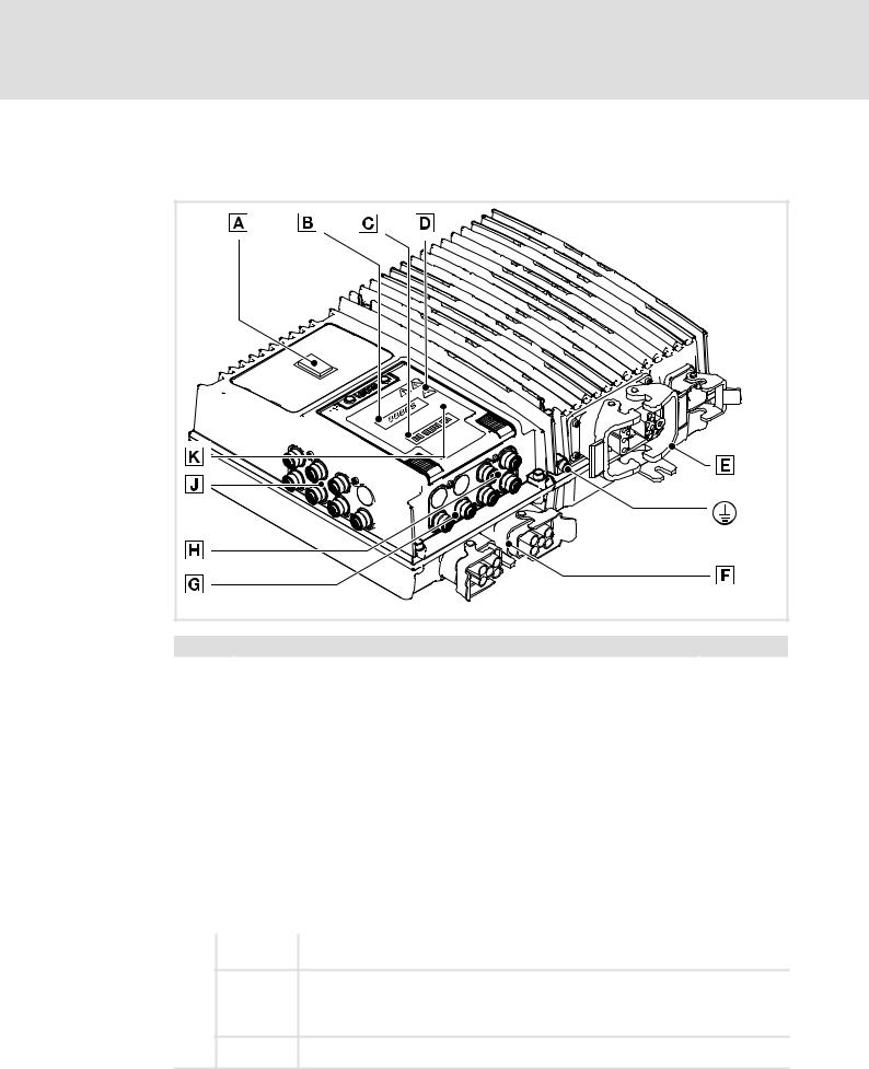
3 |
Product description |
Overview of standard devices
EMS version
E84DWGA015 b |
Control elements and connection overview of the EMS version
Pos. |
|
Description/function |
Page(s) |
|
|
0 |
|
Control element, various versions, optional |
23 |
|
|
|
|
|
|
|
|
1 |
|
Display for values and messages, 5 characters |
165 |
|
|
|
|
|
|
|
|
2 |
|
LED status display |
159 |
|
|
|
|
|
|
|
|
3 |
|
Warning symbols |
See below |
|
|
|
|
|
|
|
|
4 |
|
Motor and brake resistor connections |
From 87 |
|
|
|
|
|
|
|
|
5 |
|
Mains connections and EMS−specific communication |
|
||
|
|
|
|||
|
|
|
|
|
|
6 |
|
Fieldbus connections |
From 64 |
|
|
|
|
|
|
|
|
7 |
|
Input and output connections |
|
||
|
|
|
|||
|
|
|
|
|
|
9 |
|
EMS extension connection |
22 |
|
|
|
|
|
|
|
|
: |
|
Infrared receiver/transmitter |
165 |
|
|
|
|
|
|
|
|
+ |
|
PE connections, M6 thread |
− |
|
|
|
|
|
|
|
|
Pos. |
Icon |
Description |
|
|
|
|
|
|
|
|
|
{Long discharge time: All power terminals remain live for up to 3 minutes after mains disconnection!
}High discharge current: Carry out fixed installation and PE connection according to EN 61800−5−1!
3 |
|
|
|
|
Electrostatic sensitive devices: Before working on the device, the personnel must be free |
||
' |
|||
of electrostatic charge! |
|||
|
|
||
|Hot surface: Risk of burns! Hot surfaces should not be touched without wearing protective gloves.
26 |
l |
EDS84DPS424 EN 5.0

Product description |
3 |
Communication
CAN port
3.5Communication
The available combinations of communication and connection system can be seen from the table.
Type code characteristics |
|
|
Connection system version |
|
|
||||
|
Communication |
Input / |
Fieldbus |
|
SSI |
Analog input |
CAN on board |
|
|
|
|
|
|||||||
|
|
|
|||||||
|
(fieldbus) |
output area |
|
|
|
3) |
|
|
|
|
|
configuration |
|
|
|
|
|
|
|
|
|
Push−pull |
M12 |
M12 |
M12 |
M12 |
|
||
|
|
|
|
||||||
CANopen 1) |
|
|
|
|
|
|
|
|
|
|
C |
1 |
− |
|
þ |
− |
þ |
− |
|
|
|
|
|
|
|
|
|
|
|
|
5 |
− |
|
þ |
þ |
− |
− |
|
|
|
|
|
|
||||||
|
|
|
|
|
|
|
|
|
|
PROFIBUS |
|
|
|
|
|
|
|
|
|
|
|
|
|
|
|
|
|
|
|
|
|
1 |
− |
|
þ |
− |
þ |
− |
|
|
|
|
|
|
|
|
|
|
|
|
P |
3 |
− |
|
þ |
− |
þ |
þ2) |
|
|
5 |
− |
|
þ |
þ |
− |
− |
|
|
|
|
|
|
||||||
|
|
|
|
|
|
|
|
|
|
|
|
7 |
− |
|
þ |
þ |
− |
þ2) |
|
PROFINET / EtherNet/IP 1) |
|
|
|
|
|
|
|
||
|
|
1 |
− |
|
þ |
− |
þ |
− |
|
|
|
|
|
|
|
|
|
|
|
|
|
2 |
þ |
|
− |
− |
þ |
− |
|
|
|
|
|
|
|
|
|
|
|
|
|
3 |
− |
|
þ |
− |
þ |
þ2) |
|
|
R / G |
4 |
þ |
|
− |
− |
þ |
þ2) |
|
|
5 |
− |
|
þ |
þ |
− |
− |
|
|
|
|
|
|
||||||
|
|
|
|
|
|
|
|
|
|
|
|
6 |
þ |
|
− |
þ |
− |
− |
|
|
|
|
|
|
|
|
|
|
|
|
|
7 |
− |
|
þ |
þ |
− |
þ2) |
|
|
|
8 |
þ |
|
− |
þ |
− |
þ2) |
|
þ designed
1)cannot be combined with safety options 20 and 30
2)cannot be combined with safety option 30
3)not in StateLine version
−impossible
3.5.1CAN port
Detailed information on CAN can be found in the software manual.
CAN on board
"CAN on board" is only suited for short point−to−point connections between two controllers, e.g. for synchronisation. Pay attention to notes on EMC−compliant wiring and short cable lengths as there is no isolation towards the control electronics of the controller.
Node address and baud rate must be parameterised using the »Engineer«.
CANopen
CANopen is executed as isolated fieldbus and suited for multiple−node networks.
In case of fieldbuses, node address and baud rate can be set using the DIP switch under the service hatch or parameterised using the »Engineer«.
EDS84DPS424 EN 5.0
l |
27 |

3 Product description
Communication
Infrared remote control receiver
3.5.2Infrared remote control receiver
For remote control, the devices are equipped with an infrared receiver (IrRC) (supported from SW version 12 onwards).
The actions enabled by the infrared remote control (LDEZIRRC) are freely programmable. For more information see the software manual and the online help for the LS_IRInterface system block.
) Note!
A trouble−free operation of the optical interface requires:
ƒClear line of sight between transmitter and receiver
–Maximum distance IrRC: ~ 5 m
–Maximum distance IrDA: ~ 1 m
–Angle of incidence: ~ 30 °
–Avoid direct solar radiation
–Environment without interfering transmitter (e.g. from adjacent stations)
ƒClean and scratch−free service hatch
3.5.3Extensions in EMS version
For EMS device versions, additional interfaces are implemented for control :
ƒAdditional digital inputs and outputs
ƒInfrared data interface (IrDA)
ƒRS485 and/or RS422 serial interface
The type designation indicates which extensions are implemented in a device (¶ 23).
Overview of EMS extensions
Indicator in the |
|
|
|
Connection |
|
|
type code |
Digital I/O |
RS485 |
|
RS422 |
CANopen master PLC |
|
|
|
|||||
|
|
|
||||
|
X45, X46, X47, X48 |
|
X81, X82 |
X34 |
|
|
|
|
|
||||
|
M12, 5−pole, A−coded |
M12, 8−pole, A−coded |
M12, 5−pole, A−coded |
|
||
|
|
|
|
|
|
|
B |
6 x DI |
2 x |
|
− |
þ |
|
|
|
|
|
|
|
|
C |
2 x DI/O |
1 x |
|
1 x |
þ |
|
D |
(X46 configurable) |
− |
|
2 x |
þ |
|
|
|
|
||||
þ designed
−impossible
28 |
l |
EDS84DPS424 EN 5.0

Product description |
3 |
Communication
Infrared interface
3.5.4Infrared interface
The EMS versions come with an implemented infrared interface for data transfer (IrDA).
The actions enabled via the interface or the reading of parameter data (codes) are freely programmable in the PLC program.
) Note!
A trouble−free operation of the optical interface requires:
ƒClear line of sight between transmitter and receiver
–Maximum distance IrRC: ~ 5 m
–Maximum distance IrDA: ~ 1 m
–Angle of incidence: ~ 30 °
–Avoid direct solar radiation
–Environment without interfering transmitter (e.g. from adjacent stations)
ƒClean and scratch−free service hatch
EDS84DPS424 EN 5.0
l |
29 |

3 Product description
Concepts for the mains connection
Concepts for the connection of individual axes
3.6Concepts for the mains connection
8400 protec controllers support the implementation of various concepts for the mains connection. Here, a distinction is drawn between wiring using a:
ƒStandard cable − commercially available cable
ƒHybrid cable − special cable for mains voltage and buffer/control voltage, including shielding if required
The following must be observed when selecting the wiring:
ƒPermissible back−up fuse: max. 32 A
ƒPermissible current for plug contacts 24 V supply: max. 10 A
ƒSelect the cable cross−sections in compliance with applicable standards and directives.
–Mains/PE: max. 6 mm2
–24 V supply: max. 2.5 mm2
3.6.1Concepts for the connection of individual axes
The following versions are possible according to device version (see type code for mains connection system):
Standard cable •
The mains voltage is connected to the controller by means of a standard cable (plug X10).
The 24 V supply of the controller is generated inside the device (mains−operated supply). After the mains voltage has been switched off, all device functions including the control electronics are deactivated. The switch function of Ethernet fieldbuses is also inactive.
Hybrid cable with external 24 V buffer voltage ‚
The mains voltage and an external 24 V buffer voltage are fed using a hybrid cable (plug X10). Depending on the state of the external 24 V supply, it is possible for the control electronics to remain active even if the mains is switched off.
Standard cable with external 24 V buffer voltage ƒ
Since the connector housings only allow for one cable access per Q4/2 connector, the E84DxM... device version (loop−through technique) can be used to implement this concept for connection.
Here, the mains voltage is connected to the controller by means of a standard cable (plug X10). The external 24 V buffer voltage is connected by means of a standard cable (plug X11). Depending on the state of the external 24 V supply, it is possible for the control electronics to remain active even if the mains is switched off.
) Note!
This concept for connection implies that the mains voltage at plug X10 is also applied at plug X11 at the same time.
30 |
l |
EDS84DPS424 EN 5.0
 Loading...