


 Loading...
Inverter
8400
Inverter Drives 8400 StateLine C _ _ _ _ _ _ _ _
E84AVSCxxxxx...
Reference manual |
EN |
|
|
Ä.OT7ä 13465122
L

Overview of technical documentation for Inverter Drives 8400
_ _ _ _ _ _ _ _ _ _ _ _ _ _ _ _ _ _ _ _ _ _ _ _ _ _ _ _ _ _ _ _ _ _ _ _ _ _ _ _ _ _ _ _ _ _ _ _ _ _ _ _ _ _ _ _ _ _ _ _ _ _ _ _
Project planning, selection & ordering
8400 hardware manualCatalogue
Mounting & wiring
MA 8400 BaseLine/StateLine/HighLine/TopLine
MA for the communication module
MA for the extension module
MA for the safety module
MA for the accessories
Parameterisation
BA keypad
SW 8400 BaseLine
SW 8400 StateLine
SW 8400 HighLine
SW 8400 TopLine
KHB for the communication module
Drive commissioning
SW 8400 BaseLine/StateLine/HighLine/TopLine
chapter "Commissioning"
chapter "Diagnostics & error management"
Remote maintenance manual
Networking
KHB for the communication medium used
Legend:
Printed documentation
Online documentation (PDF/Engineer online help)
Abbreviations used:
BA Operating Instructions KHB Communication manual MA Mounting instructions
SW Software/reference manual
This documentation
2 |
Lenze · 8400 StateLine · Reference manual · DMS 12.0 EN · 06/2014 · TD05/TD14 |
Contents
_ _ _ _ _ _ _ _ _ _ _ _ _ _ _ _ _ _ _ _ _ _ _ _ _ _ _ _ _ _ _ _ _ _ _ _ _ _ _ _ _ _ _ _ _ _ _ _ _ _ _ _ _ _ _ _ _ _ _ _ _ _ _ _
1 |
About this documentation _ _ _ _ _ _ _ _ _ _ _ _ _ _ _ _ _ _ _ _ _ _ _ _ _ _ _ _ _ _ _ _ _ _ _ _ _ _ _ |
15 |
||||||
1.1 |
Document history _ _ _ _ _ _ _ _ _ _ _ _ _ _ _ _ _ _ _ _ _ _ _ _ _ _ _ _ _ _ _ _ _ _ _ _ _ _ _ _ _ _ _ _ |
15 |
||||||
1.2 |
Conventions used |
_ _ _ _ _ _ _ _ _ _ _ _ _ _ _ _ _ _ _ _ _ _ _ _ _ _ _ _ _ _ _ _ _ _ _ _ _ _ _ _ _ _ _ _ |
16 |
|||||
1.3 |
Terminology used |
_ _ _ _ _ _ _ _ _ _ _ _ _ _ _ _ _ _ _ _ _ _ _ _ _ _ _ _ _ _ _ _ _ _ _ _ _ _ _ _ _ _ _ _ |
17 |
|||||
1.4 |
Definition of the notes used |
_ _ _ _ _ _ _ _ _ _ _ _ _ _ _ _ _ _ _ _ _ _ _ _ _ _ _ _ _ _ _ _ _ _ _ _ _ _ |
19 |
|||||
2 |
Introduction: Parameterising the controller _ _ _ _ _ _ _ _ _ _ _ _ _ _ _ _ _ _ _ _ _ _ _ _ _ _ _ _ _ _ |
20 |
||||||
2.1 |
Integrated technology applications |
_ _ _ _ _ _ _ _ _ _ _ _ _ _ _ _ _ _ _ _ _ _ _ _ _ _ _ _ _ _ _ _ _ _ |
22 |
|||||
|
2.1.1 |
Purpose of the technology applications _ _ _ _ _ _ _ _ _ _ _ _ _ _ _ _ _ _ _ _ _ _ _ _ _ _ _ |
23 |
|||||
|
2.1.2 |
Application cases for a technology application _ _ _ _ _ _ _ _ _ _ _ _ _ _ _ _ _ _ _ _ _ _ _ |
23 |
|||||
|
2.1.3 |
Technology application = function block interconnection _ _ _ _ _ _ _ _ _ _ _ _ _ _ _ _ _ |
24 |
|||||
2.2 |
Selection of the appropriate commissioning tool _ _ _ _ _ _ _ _ _ _ _ _ _ _ _ _ _ _ _ _ _ _ _ _ _ _ _ |
25 |
||||||
|
2.2.1 |
Overview: Accessories for commissioning |
_ _ _ _ _ _ _ _ _ _ _ _ _ _ _ _ _ _ _ _ _ _ _ _ _ |
26 |
||||
2.3 |
General notes on parameters _ _ _ _ _ _ _ _ _ _ _ _ _ _ _ _ _ _ _ _ _ _ _ _ _ _ _ _ _ _ _ _ _ _ _ _ _ _ |
27 |
||||||
|
2.3.1 |
Changing the parameterisation with the keypad |
_ _ _ _ _ _ _ _ _ _ _ _ _ _ _ _ _ _ _ _ _ |
28 |
||||
|
2.3.2 |
Change parameter settings with PC and Lenze software _ _ _ _ _ _ _ _ _ _ _ _ _ _ _ _ _ |
31 |
|||||
|
2.3.3 |
Save parameter settings in the memory module safe against mains failure _ _ _ _ _ _ _ |
32 |
|||||
|
2.3.4 |
User menu for quick access to frequently used parameters _ _ _ _ _ _ _ _ _ _ _ _ _ _ _ _ |
34 |
|||||
2.4 |
Device access protection _ _ _ _ _ _ _ _ _ _ _ _ _ _ _ _ _ _ _ _ _ _ _ _ _ _ _ _ _ _ _ _ _ _ _ _ _ _ _ _ |
35 |
||||||
|
2.4.1 |
Password protection _ _ _ _ _ _ _ _ _ _ _ _ _ _ _ _ _ _ _ _ _ _ _ _ _ _ _ _ _ _ _ _ _ _ _ _ _ |
36 |
|||||
|
2.4.2 |
Individual password protection for single communication channels _ _ _ _ _ _ _ _ _ _ _ |
38 |
|||||
|
2.4.3 |
Device personalisation _ _ _ _ _ _ _ _ _ _ _ _ _ _ _ _ _ _ _ _ _ _ _ _ _ _ _ _ _ _ _ _ _ _ _ _ |
40 |
|||||
|
2.4.4 |
Unlocking the controller with a MasterPin _ _ _ _ _ _ _ _ _ _ _ _ _ _ _ _ _ _ _ _ _ _ _ _ _ |
42 |
|||||
2.5 |
Device identification _ _ _ _ _ _ _ _ _ _ _ _ _ _ _ _ _ _ _ _ _ _ _ _ _ _ _ _ _ _ _ _ _ _ _ _ _ _ _ _ _ _ |
43 |
||||||
|
2.5.1 |
Automatic acceptance of the device name in the »Engineer« _ _ _ _ _ _ _ _ _ _ _ _ _ _ _ |
43 |
|||||
|
2.5.2 |
Extended item designation |
_ _ _ _ _ _ _ _ _ _ _ _ _ _ _ _ _ _ _ _ _ _ _ _ _ _ _ _ _ _ _ _ _ |
43 |
||||
3 |
Commissioning _ _ _ _ _ _ _ _ _ _ _ _ _ _ _ _ _ _ _ _ _ _ _ _ _ _ _ _ _ _ _ _ _ _ _ _ _ _ _ _ _ _ _ _ _ |
44 |
||||||
3.1 |
Safety instructions with regard to commissioning |
_ _ _ _ _ _ _ _ _ _ _ _ _ _ _ _ _ _ _ _ _ _ _ _ _ _ |
45 |
|||||
3.2 |
Notes on motor control _ _ _ _ _ _ _ _ _ _ _ _ _ _ _ _ _ _ _ _ _ _ _ _ _ _ _ _ _ _ _ _ _ _ _ _ _ _ _ _ _ |
46 |
||||||
3.3 |
Preconditions for commissioning with the »Engineer« _ _ _ _ _ _ _ _ _ _ _ _ _ _ _ _ _ _ _ _ _ _ _ _ |
47 |
||||||
3.4 |
Trouble-shooting during commissioning _ _ _ _ _ _ _ _ _ _ _ _ _ _ _ _ _ _ _ _ _ _ _ _ _ _ _ _ _ _ _ |
48 |
||||||
3.5 |
Commissioning wizard 8400 |
_ _ _ _ _ _ _ _ _ _ _ _ _ _ _ _ _ _ _ _ _ _ _ _ _ _ _ _ _ _ _ _ _ _ _ _ _ _ |
48 |
|||||
3.6 |
Manual motor direction of rotation check (manual control) |
_ _ _ _ _ _ _ _ _ _ _ _ _ _ _ _ _ _ _ _ _ |
50 |
|||||
3.7 |
Commissioning of the "Actuating drive speed" technology application _ _ _ _ _ _ _ _ _ _ _ _ _ _ _ |
51 |
||||||
|
3.7.1 |
Prepare controller for commissioning _ _ _ _ _ _ _ _ _ _ _ _ _ _ _ _ _ _ _ _ _ _ _ _ _ _ _ _ |
52 |
|||||
|
3.7.2 |
Creating an »Engineer« project & going online _ _ _ _ _ _ _ _ _ _ _ _ _ _ _ _ _ _ _ _ _ _ _ |
53 |
|||||
|
3.7.3 |
Parameterising the motor control _ _ _ _ _ _ _ _ _ _ _ _ _ _ _ _ _ _ _ _ _ _ _ _ _ _ _ _ _ _ |
54 |
|||||
|
3.7.4 |
Parameterise application _ _ _ _ _ _ _ _ _ _ _ _ _ _ _ _ _ _ _ _ _ _ _ _ _ _ _ _ _ _ _ _ _ _ _ |
55 |
|||||
|
3.7.5 |
Saving parameter settings safe against mains failure _ _ _ _ _ _ _ _ _ _ _ _ _ _ _ _ _ _ _ |
57 |
|||||
|
3.7.6 |
Enable controller and test application _ _ _ _ _ _ _ _ _ _ _ _ _ _ _ _ _ _ _ _ _ _ _ _ _ _ _ _ |
57 |
|||||
3.8 |
Commissioning of the "Switch-off positioning" technology application _ _ _ _ _ _ _ _ _ _ _ _ _ _ _ |
59 |
||||||
|
3.8.1 |
Prepare controller for commissioning _ _ _ _ _ _ _ _ _ _ _ _ _ _ _ _ _ _ _ _ _ _ _ _ _ _ _ _ |
61 |
|||||
|
3.8.2 |
Creating an »Engineer« project & going online _ _ _ _ _ _ _ _ _ _ _ _ _ _ _ _ _ _ _ _ _ _ _ |
62 |
|||||
|
3.8.3 |
Parameterising the motor control _ _ _ _ _ _ _ _ _ _ _ _ _ _ _ _ _ _ _ _ _ _ _ _ _ _ _ _ _ _ |
63 |
|||||
|
3.8.4 |
Parameterise application _ _ _ _ _ _ _ _ _ _ _ _ _ _ _ _ _ _ _ _ _ _ _ _ _ _ _ _ _ _ _ _ _ _ _ |
64 |
|||||
|
3.8.5 |
Saving parameter settings safe against mains failure _ _ _ _ _ _ _ _ _ _ _ _ _ _ _ _ _ _ _ |
66 |
|||||
|
3.8.6 |
Enable controller and test application _ _ _ _ _ _ _ _ _ _ _ _ _ _ _ _ _ _ _ _ _ _ _ _ _ _ _ _ |
66 |
|||||
3.9 |
PC manual control _ _ _ _ _ _ _ _ _ _ _ _ _ _ _ _ _ _ _ _ _ _ _ _ _ _ _ _ _ _ _ _ _ _ _ _ _ _ _ _ _ _ _ _ |
67 |
||||||
|
3.9.1 |
Activate PC manual control |
_ _ _ _ _ _ _ _ _ _ _ _ _ _ _ _ _ _ _ _ _ _ _ _ _ _ _ _ _ _ _ _ _ |
67 |
||||
|
3.9.2 |
Speed control _ _ _ _ _ _ _ _ _ _ _ _ _ _ _ _ _ _ _ _ _ _ _ _ _ _ _ _ _ _ _ _ _ _ _ _ _ _ _ _ _ |
70 |
|||||
Lenze · 8400 StateLine · Reference manual · DMS 12.0 EN · 06/2014 · TD05/TD14 |
3 |
Contents
_ _ _ _ _ _ _ _ _ _ _ _ _ _ _ _ _ _ _ _ _ _ _ _ _ _ _ _ _ _ _ _ _ _ _ _ _ _ _ _ _ _ _ _ _ _ _ _ _ _ _ _ _ _ _ _ _ _ _ _ _ _ _ _
4 |
Device control (DCTRL) |
_ _ _ _ _ _ _ _ _ _ _ _ _ _ _ _ _ _ _ _ _ _ _ _ _ _ _ _ _ _ _ _ _ _ _ _ _ _ _ _ _ |
72 |
|||||||
4.1 |
Device commands (C00002/x) _ _ _ _ _ _ _ _ _ _ _ _ _ _ _ _ _ _ _ _ _ _ _ _ _ _ _ _ _ _ _ _ _ _ _ _ _ |
74 |
||||||||
|
4.1.1 |
Load Lenze setting _ _ _ _ _ _ _ _ _ _ _ _ _ _ _ _ _ _ _ _ _ _ _ _ _ _ _ _ _ _ _ _ _ _ _ _ _ _ |
77 |
|||||||
|
4.1.2 |
Load all parameter sets _ _ _ _ _ _ _ _ _ _ _ _ _ _ _ _ _ _ _ _ _ _ _ _ _ _ _ _ _ _ _ _ _ _ _ _ |
78 |
|||||||
|
4.1.3 |
Save all parameter sets _ _ _ _ _ _ _ _ _ _ _ _ _ _ _ _ _ _ _ _ _ _ _ _ _ _ _ _ _ _ _ _ _ _ _ _ |
79 |
|||||||
|
4.1.4 |
Enable/Inhibit controller _ _ _ _ _ _ _ _ _ _ _ _ _ _ _ _ _ _ _ _ _ _ _ _ _ _ _ _ _ _ _ _ _ _ _ |
80 |
|||||||
|
4.1.5 |
Activate/deactivate quick stop |
_ _ _ _ _ _ _ _ _ _ _ _ _ _ _ _ _ _ _ _ _ _ _ _ _ _ _ _ _ _ _ |
81 |
||||||
|
4.1.6 |
Reset error |
_ _ _ _ _ _ _ _ _ _ _ _ _ _ _ _ _ _ _ _ _ _ _ _ _ _ _ _ _ _ _ _ _ _ _ _ _ _ _ _ _ _ |
82 |
||||||
|
4.1.7 |
Delete logbook _ _ _ _ _ _ _ _ _ _ _ _ _ _ _ _ _ _ _ _ _ _ _ _ _ _ _ _ _ _ _ _ _ _ _ _ _ _ _ _ |
82 |
|||||||
|
4.1.8 |
Device search function _ _ _ _ _ _ _ _ _ _ _ _ _ _ _ _ _ _ _ _ _ _ _ _ _ _ _ _ _ _ _ _ _ _ _ _ |
83 |
|||||||
4.2 |
Device state machine and device states |
_ _ _ _ _ _ _ _ _ _ _ _ _ _ _ _ _ _ _ _ _ _ _ _ _ _ _ _ _ _ _ _ |
84 |
|||||||
|
4.2.1 |
FirmwareUpdate |
_ _ _ _ _ _ _ _ _ _ _ _ _ _ _ _ _ _ _ _ _ _ _ _ _ _ _ _ _ _ _ _ _ _ _ _ _ _ _ |
85 |
||||||
|
4.2.2 |
Init _ _ _ _ _ _ _ _ _ _ _ _ _ _ _ _ _ _ _ _ _ _ _ _ _ _ _ _ _ _ _ _ _ _ _ _ _ _ _ _ _ _ _ _ _ _ _ |
86 |
|||||||
|
4.2.3 |
Ident _ _ _ _ _ _ _ _ _ _ _ _ _ _ _ _ _ _ _ _ _ _ _ _ _ _ _ _ _ _ _ _ _ _ _ _ _ _ _ _ _ _ _ _ _ _ |
87 |
|||||||
|
4.2.4 |
SafeTorqueOff |
_ _ _ _ _ _ _ _ _ _ _ _ _ _ _ _ _ _ _ _ _ _ _ _ _ _ _ _ _ _ _ _ _ _ _ _ _ _ _ _ |
88 |
||||||
|
4.2.5 |
ReadyToSwitchOn |
_ _ _ _ _ _ _ _ _ _ _ _ _ _ _ _ _ _ _ _ _ _ _ _ _ _ _ _ _ _ _ _ _ _ _ _ _ _ |
89 |
||||||
|
4.2.6 |
SwitchedOn _ _ _ _ _ _ _ _ _ _ _ _ _ _ _ _ _ _ _ _ _ _ _ _ _ _ _ _ _ _ _ _ _ _ _ _ _ _ _ _ _ _ |
90 |
|||||||
|
4.2.7 |
OperationEnabled |
_ _ _ _ _ _ _ _ _ _ _ _ _ _ _ _ _ _ _ _ _ _ _ _ _ _ _ _ _ _ _ _ _ _ _ _ _ _ |
91 |
||||||
|
4.2.8 |
TroubleQSP |
_ _ _ _ _ _ _ _ _ _ _ _ _ _ _ _ _ _ _ _ _ _ _ _ _ _ _ _ _ _ _ _ _ _ _ _ _ _ _ _ _ _ |
92 |
||||||
|
4.2.9 |
Trouble _ _ _ _ _ _ _ _ _ _ _ _ _ _ _ _ _ _ _ _ _ _ _ _ _ _ _ _ _ _ _ _ _ _ _ _ _ _ _ _ _ _ _ _ |
93 |
|||||||
|
4.2.10 |
Fault _ _ _ _ _ _ _ _ _ _ _ _ _ _ _ _ _ _ _ _ _ _ _ _ _ _ _ _ _ _ _ _ _ _ _ _ _ _ _ _ _ _ _ _ _ _ |
94 |
|||||||
|
4.2.11 |
SystemFault _ _ _ _ _ _ _ _ _ _ _ _ _ _ _ _ _ _ _ _ _ _ _ _ _ _ _ _ _ _ _ _ _ _ _ _ _ _ _ _ _ _ |
94 |
|||||||
4.3 |
Automatic restart after mains connection/fault... _ _ _ _ _ _ _ _ _ _ _ _ _ _ _ _ _ _ _ _ _ _ _ _ _ _ _ |
95 |
||||||||
|
4.3.1 |
"Inhibit at power-on" auto-start option _ _ _ _ _ _ _ _ _ _ _ _ _ _ _ _ _ _ _ _ _ _ _ _ _ _ _ |
95 |
|||||||
|
4.3.2 |
Auto-start option "Inhibit at Lenze setting" _ _ _ _ _ _ _ _ _ _ _ _ _ _ _ _ _ _ _ _ _ _ _ _ _ |
97 |
|||||||
4.4 |
Internal interfaces | "LS_DriveInterface" system block |
_ _ _ _ _ _ _ _ _ _ _ _ _ _ _ _ _ _ _ _ _ _ _ _ |
98 |
|||||||
|
4.4.1 |
wCANControl/wMCIControl control words _ _ _ _ _ _ _ _ _ _ _ _ _ _ _ _ _ _ _ _ _ _ _ _ _ |
101 |
|||||||
|
4.4.2 |
wDeviceStatusWord status word _ _ _ _ _ _ _ _ _ _ _ _ _ _ _ _ _ _ _ _ _ _ _ _ _ _ _ _ _ _ |
103 |
|||||||
5 |
Motor control (MCTRL) |
_ _ _ _ _ _ _ _ _ _ _ _ _ _ _ _ _ _ _ _ _ _ _ _ _ _ _ _ _ _ _ _ _ _ _ _ _ _ _ _ _ |
104 |
|||||||
5.1 |
Motor selection/Motor data |
_ _ _ _ _ _ _ _ _ _ _ _ _ _ _ _ _ _ _ _ _ _ _ _ _ _ _ _ _ _ _ _ _ _ _ _ _ _ |
105 |
|||||||
|
5.1.1 |
Selecting a motor from the motor catalogue in the »Engineer« _ _ _ _ _ _ _ _ _ _ _ _ _ _ |
109 |
|||||||
|
5.1.2 |
Automatic motor data identification _ _ _ _ _ _ _ _ _ _ _ _ _ _ _ _ _ _ _ _ _ _ _ _ _ _ _ _ |
111 |
|||||||
|
5.1.3 |
Application notes for asynchronous motors with high slip speed _ _ _ _ _ _ _ _ _ _ _ _ _ |
117 |
|||||||
5.2 |
Selecting the control mode |
_ _ _ _ _ _ _ _ _ _ _ _ _ _ _ _ _ _ _ _ _ _ _ _ _ _ _ _ _ _ _ _ _ _ _ _ _ _ _ |
118 |
|||||||
|
5.2.1 |
Selection help _ _ _ _ _ _ _ _ _ _ _ _ _ _ _ _ _ _ _ _ _ _ _ _ _ _ _ _ _ _ _ _ _ _ _ _ _ _ _ _ _ |
122 |
|||||||
5.3 |
Defining current and speed limits _ _ _ _ _ _ _ _ _ _ _ _ _ _ _ _ _ _ _ _ _ _ _ _ _ _ _ _ _ _ _ _ _ _ _ |
123 |
||||||||
5.4 |
V/f characteristic control (VFCplus) _ _ _ _ _ _ _ _ _ _ _ _ _ _ _ _ _ _ _ _ _ _ _ _ _ _ _ _ _ _ _ _ _ _ _ |
126 |
||||||||
|
5.4.1 |
Parameterisation dialog/signal flow |
_ _ _ _ _ _ _ _ _ _ _ _ _ _ _ _ _ _ _ _ _ _ _ _ _ _ _ _ |
127 |
||||||
|
5.4.2 |
Basic settings _ _ _ _ _ _ _ _ _ _ _ _ _ _ _ _ _ _ _ _ _ _ _ _ _ _ _ _ _ _ _ _ _ _ _ _ _ _ _ _ _ |
129 |
|||||||
|
|
5.4.2.1 |
Defining the V/f characteristic shape _ _ _ _ _ _ _ _ _ _ _ _ _ _ _ _ _ _ _ _ _ |
130 |
||||||
|
|
5.4.2.2 |
Defining current limits (Imax controller) |
_ _ _ _ _ _ _ _ _ _ _ _ _ _ _ _ _ _ _ |
131 |
|||||
|
5.4.3 |
Optimising the control mode |
_ _ _ _ _ _ _ _ _ _ _ _ _ _ _ _ _ _ _ _ _ _ _ _ _ _ _ _ _ _ _ _ |
132 |
||||||
|
|
5.4.3.1 |
Adapting the V/f base frequency |
_ _ _ _ _ _ _ _ _ _ _ _ _ _ _ _ _ _ _ _ _ _ _ |
133 |
|||||
|
|
5.4.3.2 |
Adapting the Vmin boost |
_ _ _ _ _ _ _ _ _ _ _ _ _ _ _ _ _ _ _ _ _ _ _ _ _ _ _ |
135 |
|||||
|
|
5.4.3.3 |
Optimising the Imax controller |
_ _ _ _ _ _ _ _ _ _ _ _ _ _ _ _ _ _ _ _ _ _ _ _ |
136 |
|||||
|
|
5.4.3.4 |
Optimising the stalling behaviour _ _ _ _ _ _ _ _ _ _ _ _ _ _ _ _ _ _ _ _ _ _ _ |
137 |
||||||
|
|
5.4.3.5 |
Torque limitation _ _ _ _ _ _ _ _ _ _ _ _ _ _ _ _ _ _ _ _ _ _ _ _ _ _ _ _ _ _ _ _ |
138 |
||||||
|
|
5.4.3.6 |
Defining a user-defined V/f characteristic |
_ _ _ _ _ _ _ _ _ _ _ _ _ _ _ _ _ _ |
140 |
|||||
|
5.4.4 |
Remedies for undesired drive behaviour _ _ _ _ _ _ _ _ _ _ _ _ _ _ _ _ _ _ _ _ _ _ _ _ _ _ |
143 |
|||||||
4 |
Lenze · 8400 StateLine · Reference manual · DMS 12.0 EN · 06/2014 · TD05/TD14 |
Contents
_ _ _ _ _ _ _ _ _ _ _ _ _ _ _ _ _ _ _ _ _ _ _ _ _ _ _ _ _ _ _ _ _ _ _ _ _ _ _ _ _ _ _ _ _ _ _ _ _ _ _ _ _ _ _ _ _ _ _ _ _ _ _ _
5.5 |
V/f characteristic control - energy-saving (VFCplusEco) _ _ _ _ _ _ _ _ _ _ _ _ _ _ _ _ _ _ _ _ _ _ _ _ |
144 |
||||||||
|
5.5.1 |
Parameterisation dialog/signal flow |
_ _ _ _ _ _ _ _ _ _ _ _ _ _ _ _ _ _ _ _ _ _ _ _ _ _ _ _ |
145 |
||||||
|
5.5.2 |
Comparison of VFCplusEco - VFCplus |
_ _ _ _ _ _ _ _ _ _ _ _ _ _ _ _ _ _ _ _ _ _ _ _ _ _ _ _ |
147 |
||||||
|
5.5.3 |
Basic settings _ _ _ _ _ _ _ _ _ _ _ _ _ _ _ _ _ _ _ _ _ _ _ _ _ _ _ _ _ _ _ _ _ _ _ _ _ _ _ _ _ |
148 |
|||||||
|
5.5.4 |
Optimising the control mode |
_ _ _ _ _ _ _ _ _ _ _ _ _ _ _ _ _ _ _ _ _ _ _ _ _ _ _ _ _ _ _ _ |
149 |
||||||
|
|
5.5.4.1 |
Improving the behaviour at high dynamic load changes _ _ _ _ _ _ _ _ _ _ _ |
150 |
||||||
|
|
5.5.4.2 |
Adapting the slope limitation for lowering the Eco function |
_ _ _ _ _ _ _ _ |
151 |
|||||
|
|
5.5.4.3 |
Optimising the cos/phi controller _ _ _ _ _ _ _ _ _ _ _ _ _ _ _ _ _ _ _ _ _ _ _ |
151 |
||||||
|
5.5.5 |
Remedies for undesired drive behaviour |
_ _ _ _ _ _ _ _ _ _ _ _ _ _ _ _ _ _ _ _ _ _ _ _ _ _ |
152 |
||||||
5.6 V/f control (VFCplus + encoder) _ _ _ _ _ _ _ _ _ _ _ _ _ _ _ _ _ _ _ _ _ _ _ _ _ _ _ _ _ _ _ _ _ _ _ _ _ |
154 |
|||||||||
|
5.6.1 |
Parameterisation dialog/signal flow |
_ _ _ _ _ _ _ _ _ _ _ _ _ _ _ _ _ _ _ _ _ _ _ _ _ _ _ _ |
155 |
||||||
|
5.6.2 |
Basic settings _ _ _ _ _ _ _ _ _ _ _ _ _ _ _ _ _ _ _ _ _ _ _ _ _ _ _ _ _ _ _ _ _ _ _ _ _ _ _ _ _ |
157 |
|||||||
|
|
5.6.2.1 |
Parameterising the slip regulator _ _ _ _ _ _ _ _ _ _ _ _ _ _ _ _ _ _ _ _ _ _ _ |
158 |
||||||
5.7 Sensorless vector control (SLVC) |
_ _ _ _ _ _ _ _ _ _ _ _ _ _ _ _ _ _ _ _ _ _ _ _ _ _ _ _ _ _ _ _ _ _ _ _ |
161 |
||||||||
|
5.7.1 |
Parameterisation dialog/signal flow |
_ _ _ _ _ _ _ _ _ _ _ _ _ _ _ _ _ _ _ _ _ _ _ _ _ _ _ _ |
162 |
||||||
|
5.7.2 |
Types of control _ _ _ _ _ _ _ _ _ _ _ _ _ _ _ _ _ _ _ _ _ _ _ _ _ _ _ _ _ _ _ _ _ _ _ _ _ _ _ _ |
164 |
|||||||
|
|
5.7.2.1 |
Speed control with torque limitation _ _ _ _ _ _ _ _ _ _ _ _ _ _ _ _ _ _ _ _ _ |
164 |
||||||
|
|
5.7.2.2 |
Torque control with speed limitation _ _ _ _ _ _ _ _ _ _ _ _ _ _ _ _ _ _ _ _ _ |
165 |
||||||
|
5.7.3 |
Basic settings _ _ _ _ _ _ _ _ _ _ _ _ _ _ _ _ _ _ _ _ _ _ _ _ _ _ _ _ _ _ _ _ _ _ _ _ _ _ _ _ _ |
166 |
|||||||
|
5.7.4 |
Optimising the control mode |
_ _ _ _ _ _ _ _ _ _ _ _ _ _ _ _ _ _ _ _ _ _ _ _ _ _ _ _ _ _ _ _ |
167 |
||||||
|
|
5.7.4.1 |
Optimising the starting performance after a controller enable _ _ _ _ _ _ _ |
167 |
||||||
|
|
5.7.4.2 |
Optimise speed controller |
_ _ _ _ _ _ _ _ _ _ _ _ _ _ _ _ _ _ _ _ _ _ _ _ _ _ _ |
168 |
|||||
|
|
5.7.4.3 |
Optimising dynamic performance and field weakening behaviour _ _ _ _ _ |
169 |
||||||
|
|
5.7.4.4 |
Optimising the stalling behaviour _ _ _ _ _ _ _ _ _ _ _ _ _ _ _ _ _ _ _ _ _ _ _ |
170 |
||||||
|
|
5.7.4.5 |
Optimise response to setpoint changes and determine mass inertia _ _ _ _ |
171 |
||||||
|
|
5.7.4.6 |
Slip calculation from motor equivalent circuit diagram data |
_ _ _ _ _ _ _ _ |
174 |
|||||
|
|
5.7.4.7 |
Optimising field feedforward control and torque feedforward control _ _ _ |
175 |
||||||
|
5.7.5 |
Remedies for undesired drive behaviour |
_ _ _ _ _ _ _ _ _ _ _ _ _ _ _ _ _ _ _ _ _ _ _ _ _ _ |
176 |
||||||
5.8 |
Sensorless control for synchronous motors (SLPSM) _ _ _ _ _ _ _ _ _ _ _ _ _ _ _ _ _ _ _ _ _ _ _ _ _ |
177 |
||||||||
|
5.8.1 |
Parameterisation dialog/signal flow |
_ _ _ _ _ _ _ _ _ _ _ _ _ _ _ _ _ _ _ _ _ _ _ _ _ _ _ _ |
179 |
||||||
|
5.8.2 |
Types of control _ _ _ _ _ _ _ _ _ _ _ _ _ _ _ _ _ _ _ _ _ _ _ _ _ _ _ _ _ _ _ _ _ _ _ _ _ _ _ _ |
182 |
|||||||
|
5.8.3 |
Basic settings _ _ _ _ _ _ _ _ _ _ _ _ _ _ _ _ _ _ _ _ _ _ _ _ _ _ _ _ _ _ _ _ _ _ _ _ _ _ _ _ _ |
183 |
|||||||
|
5.8.4 |
Optimising the control mode |
_ _ _ _ _ _ _ _ _ _ _ _ _ _ _ _ _ _ _ _ _ _ _ _ _ _ _ _ _ _ _ _ |
185 |
||||||
|
|
5.8.4.1 |
Optimise current controller |
_ _ _ _ _ _ _ _ _ _ _ _ _ _ _ _ _ _ _ _ _ _ _ _ _ _ |
186 |
|||||
|
|
5.8.4.2 |
Optimise speed controller |
_ _ _ _ _ _ _ _ _ _ _ _ _ _ _ _ _ _ _ _ _ _ _ _ _ _ _ |
187 |
|||||
|
|
5.8.4.3 |
Optimise response to setpoint changes and determine mass inertia _ _ _ _ |
190 |
||||||
|
|
5.8.4.4 |
Current-dependent stator leakage inductance Ppp(I) |
_ _ _ _ _ _ _ _ _ _ _ _ |
193 |
|||||
|
|
5.8.4.5 |
Setting the current setpoint filter (band-stop filter) |
_ _ _ _ _ _ _ _ _ _ _ _ _ |
195 |
|||||
|
|
5.8.4.6 |
Adapting the max. acceleration change (jerk limitation) _ _ _ _ _ _ _ _ _ _ |
196 |
||||||
|
5.8.5 |
Pole position identification without motion _ _ _ _ _ _ _ _ _ _ _ _ _ _ _ _ _ _ _ _ _ _ _ _ |
197 |
|||||||
|
5.8.6 |
Field weakening for synchronous motors _ _ _ _ _ _ _ _ _ _ _ _ _ _ _ _ _ _ _ _ _ _ _ _ _ _ |
199 |
|||||||
5.9 |
Parameterisable additional functions |
_ _ _ _ _ _ _ _ _ _ _ _ _ _ _ _ _ _ _ _ _ _ _ _ _ _ _ _ _ _ _ _ _ |
202 |
|||||||
|
5.9.1 |
Selection of switching frequency _ _ _ _ _ _ _ _ _ _ _ _ _ _ _ _ _ _ _ _ _ _ _ _ _ _ _ _ _ _ |
202 |
|||||||
|
5.9.2 |
Operation with increased rated power |
_ _ _ _ _ _ _ _ _ _ _ _ _ _ _ _ _ _ _ _ _ _ _ _ _ _ _ |
206 |
||||||
|
5.9.3 |
Flying restart function _ _ _ _ _ _ _ _ _ _ _ _ _ _ _ _ _ _ _ _ _ _ _ _ _ _ _ _ _ _ _ _ _ _ _ _ |
208 |
|||||||
|
5.9.4 |
DC-injection braking |
_ _ _ _ _ _ _ _ _ _ _ _ _ _ _ _ _ _ _ _ _ _ _ _ _ _ _ _ _ _ _ _ _ _ _ _ _ |
211 |
||||||
|
|
5.9.4.1 |
Manual DC-injection braking (DCB) _ _ _ _ _ _ _ _ _ _ _ _ _ _ _ _ _ _ _ _ _ _ |
212 |
||||||
|
|
5.9.4.2 |
Automatic DC-injection braking (Auto-DCB) _ _ _ _ _ _ _ _ _ _ _ _ _ _ _ _ _ |
212 |
||||||
|
5.9.5 |
Slip compensation _ _ _ _ _ _ _ _ _ _ _ _ _ _ _ _ _ _ _ _ _ _ _ _ _ _ _ _ _ _ _ _ _ _ _ _ _ _ |
215 |
|||||||
|
5.9.6 |
Oscillation damping |
_ _ _ _ _ _ _ _ _ _ _ _ _ _ _ _ _ _ _ _ _ _ _ _ _ _ _ _ _ _ _ _ _ _ _ _ _ |
216 |
||||||
|
|
5.9.6.1 |
Oscillation damping voltage range _ _ _ _ _ _ _ _ _ _ _ _ _ _ _ _ _ _ _ _ _ _ |
217 |
||||||
|
|
5.9.6.2 |
Oscillation damping in the field weakening range _ _ _ _ _ _ _ _ _ _ _ _ _ _ |
218 |
||||||
|
5.9.7 |
Phase sequence reversal for correcting misconnected UVW motor phases _ _ _ _ _ _ _ _ |
219 |
|||||||
Lenze · 8400 StateLine · Reference manual · DMS 12.0 EN · 06/2014 · TD05/TD14 |
5 |
Contents
_ _ _ _ _ _ _ _ _ _ _ _ _ _ _ _ _ _ _ _ _ _ _ _ _ _ _ _ _ _ _ _ _ _ _ _ _ _ _ _ _ _ _ _ _ _ _ _ _ _ _ _ _ _ _ _ _ _ _ _ _ _ _ _
5.10 |
Encoder/feedback system _ _ _ _ _ _ _ _ _ _ _ _ _ _ _ _ _ _ _ _ _ _ _ _ _ _ _ _ _ _ _ _ _ _ _ _ _ _ _ _ |
220 |
|||
|
5.10.1 |
Parameterising digital inputs as encoder inputs _ _ _ _ _ _ _ _ _ _ _ _ _ _ _ _ _ _ _ _ _ _ |
222 |
||
|
5.10.2 |
Generation of the actual speed value _ _ _ _ _ _ _ _ _ _ _ _ _ _ _ _ _ _ _ _ _ _ _ _ _ _ _ _ |
223 |
||
|
5.10.3 |
HTL encoder at DI1/DI2 _ _ _ _ _ _ _ _ _ _ _ _ _ _ _ _ _ _ _ _ _ _ _ _ _ _ _ _ _ _ _ _ _ _ _ |
224 |
||
5.11 |
Braking operation/brake energy management _ _ _ _ _ _ _ _ _ _ _ _ _ _ _ _ _ _ _ _ _ _ _ _ _ _ _ _ |
226 |
|||
|
5.11.1 |
Setting the voltage source for braking operation _ _ _ _ _ _ _ _ _ _ _ _ _ _ _ _ _ _ _ _ _ _ |
229 |
||
|
5.11.2 |
Selecting the response to an increase of the DC-bus voltage _ _ _ _ _ _ _ _ _ _ _ _ _ _ _ |
229 |
||
|
|
5.11.2.1 |
Inverter motor brake _ _ _ _ _ _ _ _ _ _ _ _ _ _ _ _ _ _ _ _ _ _ _ _ _ _ _ _ _ _ |
231 |
|
|
5.11.3 |
Avoiding thermal overload of the brake resistor _ _ _ _ _ _ _ _ _ _ _ _ _ _ _ _ _ _ _ _ _ _ |
234 |
||
|
5.11.4 |
Control of multiple internal brake choppers in the DC-bus system _ _ _ _ _ _ _ _ _ _ _ _ |
234 |
||
5.12 |
Monitoring _ _ _ _ _ _ _ _ _ _ _ _ _ _ _ _ _ _ _ _ _ _ _ _ _ _ _ _ _ _ _ _ _ _ _ _ _ _ _ _ _ _ _ _ _ _ _ _ |
237 |
|||
|
5.12.1 |
Device overload monitoring (Ixt) |
_ _ _ _ _ _ _ _ _ _ _ _ _ _ _ _ _ _ _ _ _ _ _ _ _ _ _ _ _ _ |
238 |
|
|
5.12.2 |
Motor overload monitoring (I2xt) _ _ _ _ _ _ _ _ _ _ _ _ _ _ _ _ _ _ _ _ _ _ _ _ _ _ _ _ _ _ |
239 |
||
|
5.12.3 |
Motor overcurrent monitoring _ _ _ _ _ _ _ _ _ _ _ _ _ _ _ _ _ _ _ _ _ _ _ _ _ _ _ _ _ _ _ _ |
241 |
||
|
5.12.4 |
Motor temperature monitoring (PTC) _ _ _ _ _ _ _ _ _ _ _ _ _ _ _ _ _ _ _ _ _ _ _ _ _ _ _ _ |
242 |
||
|
5.12.5 |
Brake resistor monitoring (I2xt) |
_ _ _ _ _ _ _ _ _ _ _ _ _ _ _ _ _ _ _ _ _ _ _ _ _ _ _ _ _ _ _ |
243 |
|
|
5.12.6 |
Motor phase failure monitoring _ _ _ _ _ _ _ _ _ _ _ _ _ _ _ _ _ _ _ _ _ _ _ _ _ _ _ _ _ _ _ |
245 |
||
|
5.12.7 |
Motor phase error monitoring before operation _ _ _ _ _ _ _ _ _ _ _ _ _ _ _ _ _ _ _ _ _ _ |
246 |
||
|
5.12.8 |
Mains phase failure monitoring _ _ _ _ _ _ _ _ _ _ _ _ _ _ _ _ _ _ _ _ _ _ _ _ _ _ _ _ _ _ _ |
248 |
||
|
5.12.9 |
Maximum current monitoring _ _ _ _ _ _ _ _ _ _ _ _ _ _ _ _ _ _ _ _ _ _ _ _ _ _ _ _ _ _ _ _ |
248 |
||
|
5.12.10 |
Maximum torque monitoring _ _ _ _ _ _ _ _ _ _ _ _ _ _ _ _ _ _ _ _ _ _ _ _ _ _ _ _ _ _ _ _ |
249 |
||
|
5.12.11 |
Motor speed monitoring _ _ _ _ _ _ _ _ _ _ _ _ _ _ _ _ _ _ _ _ _ _ _ _ _ _ _ _ _ _ _ _ _ _ _ |
249 |
||
|
5.12.12 |
Encoder open-circuit monitoring |
_ _ _ _ _ _ _ _ _ _ _ _ _ _ _ _ _ _ _ _ _ _ _ _ _ _ _ _ _ _ |
250 |
|
5.13 |
Internal interfaces | System block "LS_MotorInterface" _ _ _ _ _ _ _ _ _ _ _ _ _ _ _ _ _ _ _ _ _ _ _ _ |
251 |
|||
5.14 |
Internal status signals | System block "LS_DeviceMonitor" _ _ _ _ _ _ _ _ _ _ _ _ _ _ _ _ _ _ _ _ _ _ |
257 |
|||
6 |
I/O terminals _ _ _ _ _ _ _ _ _ _ _ _ _ _ _ _ _ _ _ _ _ _ _ _ _ _ _ _ _ _ _ _ _ _ _ _ _ _ _ _ _ _ _ _ _ _ _ |
260 |
|||
6.1 |
Digital terminals _ _ _ _ _ _ _ _ _ _ _ _ _ _ _ _ _ _ _ _ _ _ _ _ _ _ _ _ _ _ _ _ _ _ _ _ _ _ _ _ _ _ _ _ _ |
261 |
|||
|
6.1.1 |
Change function assignment _ _ _ _ _ _ _ _ _ _ _ _ _ _ _ _ _ _ _ _ _ _ _ _ _ _ _ _ _ _ _ _ |
264 |
||
|
|
6.1.1.1 |
Using DI1 and DI2 as digital inputs _ _ _ _ _ _ _ _ _ _ _ _ _ _ _ _ _ _ _ _ _ _ |
265 |
|
|
|
6.1.1.2 |
Using DI1 and DI2 as frequency inputs _ _ _ _ _ _ _ _ _ _ _ _ _ _ _ _ _ _ _ _ |
266 |
|
|
|
6.1.1.3 |
Using DI1 as counting input _ _ _ _ _ _ _ _ _ _ _ _ _ _ _ _ _ _ _ _ _ _ _ _ _ _ |
270 |
|
|
6.1.2 |
Internal interfaces | System block "LS_DigitalInput" _ _ _ _ _ _ _ _ _ _ _ _ _ _ _ _ _ _ _ _ |
273 |
||
|
|
6.1.2.1 |
Output of the encoder position of the DI1/DI2 frequency input _ _ _ _ _ _ _ |
275 |
|
|
6.1.3 |
Internal interfaces | System block "LS_DigitalOutput" _ _ _ _ _ _ _ _ _ _ _ _ _ _ _ _ _ _ _ |
279 |
||
6.2 |
Analog terminals |
_ _ _ _ _ _ _ _ _ _ _ _ _ _ _ _ _ _ _ _ _ _ _ _ _ _ _ _ _ _ _ _ _ _ _ _ _ _ _ _ _ _ _ _ |
280 |
||
|
6.2.1 |
Parameterising analog input _ _ _ _ _ _ _ _ _ _ _ _ _ _ _ _ _ _ _ _ _ _ _ _ _ _ _ _ _ _ _ _ _ |
282 |
||
|
|
6.2.1.1 |
Signal adaptation by means of characteristic _ _ _ _ _ _ _ _ _ _ _ _ _ _ _ _ _ |
284 |
|
|
6.2.2 |
Parameterising analog output _ _ _ _ _ _ _ _ _ _ _ _ _ _ _ _ _ _ _ _ _ _ _ _ _ _ _ _ _ _ _ _ |
286 |
||
|
6.2.3 |
Internal interfaces | System block "LS_AnalogInput" _ _ _ _ _ _ _ _ _ _ _ _ _ _ _ _ _ _ _ _ |
287 |
||
|
6.2.4 |
Internal interfaces | System block "LS_AnalogOutput" _ _ _ _ _ _ _ _ _ _ _ _ _ _ _ _ _ _ _ |
287 |
||
6.3 |
Configuring exception handling of the output terminals _ _ _ _ _ _ _ _ _ _ _ _ _ _ _ _ _ _ _ _ _ _ _ |
288 |
|||
6.4 |
User-defined terminal assignment _ _ _ _ _ _ _ _ _ _ _ _ _ _ _ _ _ _ _ _ _ _ _ _ _ _ _ _ _ _ _ _ _ _ _ |
289 |
|||
|
6.4.1 |
Source-destination principle _ _ _ _ _ _ _ _ _ _ _ _ _ _ _ _ _ _ _ _ _ _ _ _ _ _ _ _ _ _ _ _ _ |
290 |
||
|
6.4.2 |
Changing the terminal assignment with the keypad _ _ _ _ _ _ _ _ _ _ _ _ _ _ _ _ _ _ _ _ |
291 |
||
|
6.4.3 |
Changing the terminal assignment with the »Engineer« _ _ _ _ _ _ _ _ _ _ _ _ _ _ _ _ _ |
293 |
||
6 |
Lenze · 8400 StateLine · Reference manual · DMS 12.0 EN · 06/2014 · TD05/TD14 |
Contents
_ _ _ _ _ _ _ _ _ _ _ _ _ _ _ _ _ _ _ _ _ _ _ _ _ _ _ _ _ _ _ _ _ _ _ _ _ _ _ _ _ _ _ _ _ _ _ _ _ _ _ _ _ _ _ _ _ _ _ _ _ _ _ _
7 |
Technology applications |
_ _ _ _ _ _ _ _ _ _ _ _ _ _ _ _ _ _ _ _ _ _ _ _ _ _ _ _ _ _ _ _ _ _ _ _ _ _ _ _ |
296 |
|||||
7.1 |
Selection of the technology application and the control mode _ _ _ _ _ _ _ _ _ _ _ _ _ _ _ _ _ _ _ _ |
297 |
||||||
7.2 |
TA "Actuating drive speed" _ _ _ _ _ _ _ _ _ _ _ _ _ _ _ _ _ _ _ _ _ _ _ _ _ _ _ _ _ _ _ _ _ _ _ _ _ _ _ |
298 |
||||||
|
7.2.1 |
Basic signal flow |
_ _ _ _ _ _ _ _ _ _ _ _ _ _ _ _ _ _ _ _ _ _ _ _ _ _ _ _ _ _ _ _ _ _ _ _ _ _ _ |
299 |
||||
|
7.2.2 |
Internal interfaces | application block "LA_NCtrl" |
_ _ _ _ _ _ _ _ _ _ _ _ _ _ _ _ _ _ _ _ _ |
301 |
||||
|
7.2.3 |
Terminal assignment of the control modes _ _ _ _ _ _ _ _ _ _ _ _ _ _ _ _ _ _ _ _ _ _ _ _ _ |
309 |
|||||
|
|
7.2.3.1 |
Terminals 0 _ _ _ _ _ _ _ _ _ _ _ _ _ _ _ _ _ _ _ _ _ _ _ _ _ _ _ _ _ _ _ _ _ _ _ |
310 |
||||
|
|
7.2.3.2 |
Terminals 2 _ _ _ _ _ _ _ _ _ _ _ _ _ _ _ _ _ _ _ _ _ _ _ _ _ _ _ _ _ _ _ _ _ _ _ |
311 |
||||
|
|
7.2.3.3 |
Terminals 11 _ _ _ _ _ _ _ _ _ _ _ _ _ _ _ _ _ _ _ _ _ _ _ _ _ _ _ _ _ _ _ _ _ _ |
312 |
||||
|
|
7.2.3.4 |
Terminal 16 _ _ _ _ _ _ _ _ _ _ _ _ _ _ _ _ _ _ _ _ _ _ _ _ _ _ _ _ _ _ _ _ _ _ _ |
313 |
||||
|
|
7.2.3.5 |
Keypad |
_ _ _ _ _ _ _ _ _ _ _ _ _ _ _ _ _ _ _ _ _ _ _ _ _ _ _ _ _ _ _ _ _ _ _ _ _ |
314 |
|||
|
|
7.2.3.6 |
PC |
_ _ _ _ _ _ _ _ _ _ _ _ _ _ _ _ _ _ _ _ _ _ _ _ _ _ _ _ _ _ _ _ _ _ _ _ _ _ _ _ |
315 |
|||
|
|
7.2.3.7 |
CAN _ _ _ _ _ _ _ _ _ _ _ _ _ _ _ _ _ _ _ _ _ _ _ _ _ _ _ _ _ _ _ _ _ _ _ _ _ _ _ |
316 |
||||
|
|
7.2.3.8 |
MCI |
_ _ _ _ _ _ _ _ _ _ _ _ _ _ _ _ _ _ _ _ _ _ _ _ _ _ _ _ _ _ _ _ _ _ _ _ _ _ _ |
317 |
|||
|
7.2.4 |
Process data assignment for fieldbus communication _ _ _ _ _ _ _ _ _ _ _ _ _ _ _ _ _ _ _ |
318 |
|||||
|
7.2.5 |
Setting parameters (short overview) |
_ _ _ _ _ _ _ _ _ _ _ _ _ _ _ _ _ _ _ _ _ _ _ _ _ _ _ _ |
320 |
||||
|
7.2.6 |
Configuration parameters _ _ _ _ _ _ _ _ _ _ _ _ _ _ _ _ _ _ _ _ _ _ _ _ _ _ _ _ _ _ _ _ _ _ |
322 |
|||||
7.3 |
TA "actuating drive speed (AC Drive Profile)" |
_ _ _ _ _ _ _ _ _ _ _ _ _ _ _ _ _ _ _ _ _ _ _ _ _ _ _ _ _ |
325 |
|||||
|
7.3.1 |
I/O assemblies |
_ _ _ _ _ _ _ _ _ _ _ _ _ _ _ _ _ _ _ _ _ _ _ _ _ _ _ _ _ _ _ _ _ _ _ _ _ _ _ _ |
326 |
||||
|
7.3.2 |
Basic signal flow |
_ _ _ _ _ _ _ _ _ _ _ _ _ _ _ _ _ _ _ _ _ _ _ _ _ _ _ _ _ _ _ _ _ _ _ _ _ _ _ |
327 |
||||
|
7.3.3 |
Internal interfaces | application block "LA_NCtrl" |
_ _ _ _ _ _ _ _ _ _ _ _ _ _ _ _ _ _ _ _ _ |
330 |
||||
|
7.3.4 |
Terminal assignment of the control modes _ _ _ _ _ _ _ _ _ _ _ _ _ _ _ _ _ _ _ _ _ _ _ _ _ |
339 |
|||||
|
|
7.3.4.1 |
Terminals 0 _ _ _ _ _ _ _ _ _ _ _ _ _ _ _ _ _ _ _ _ _ _ _ _ _ _ _ _ _ _ _ _ _ _ _ |
340 |
||||
|
|
7.3.4.2 |
Terminals 2 _ _ _ _ _ _ _ _ _ _ _ _ _ _ _ _ _ _ _ _ _ _ _ _ _ _ _ _ _ _ _ _ _ _ _ |
341 |
||||
|
|
7.3.4.3 |
Terminals 11 _ _ _ _ _ _ _ _ _ _ _ _ _ _ _ _ _ _ _ _ _ _ _ _ _ _ _ _ _ _ _ _ _ _ |
342 |
||||
|
|
7.3.4.4 |
Terminal 16 _ _ _ _ _ _ _ _ _ _ _ _ _ _ _ _ _ _ _ _ _ _ _ _ _ _ _ _ _ _ _ _ _ _ _ |
343 |
||||
|
|
7.3.4.5 |
Keypad |
_ _ _ _ _ _ _ _ _ _ _ _ _ _ _ _ _ _ _ _ _ _ _ _ _ _ _ _ _ _ _ _ _ _ _ _ _ |
344 |
|||
|
|
7.3.4.6 |
PC |
_ _ _ _ _ _ _ _ _ _ _ _ _ _ _ _ _ _ _ _ _ _ _ _ _ _ _ _ _ _ _ _ _ _ _ _ _ _ _ _ |
345 |
|||
|
|
7.3.4.7 |
CAN _ _ _ _ _ _ _ _ _ _ _ _ _ _ _ _ _ _ _ _ _ _ _ _ _ _ _ _ _ _ _ _ _ _ _ _ _ _ _ |
346 |
||||
|
|
7.3.4.8 |
MCI |
_ _ _ _ _ _ _ _ _ _ _ _ _ _ _ _ _ _ _ _ _ _ _ _ _ _ _ _ _ _ _ _ _ _ _ _ _ _ _ |
347 |
|||
|
7.3.5 |
Process data assignment for fieldbus communication _ _ _ _ _ _ _ _ _ _ _ _ _ _ _ _ _ _ _ |
348 |
|||||
|
|
7.3.5.1 |
Run/Stop event _ _ _ _ _ _ _ _ _ _ _ _ _ _ _ _ _ _ _ _ _ _ _ _ _ _ _ _ _ _ _ _ _ |
349 |
||||
|
|
7.3.5.2 |
Scaling of speed and torque values |
_ _ _ _ _ _ _ _ _ _ _ _ _ _ _ _ _ _ _ _ _ _ |
350 |
|||
|
7.3.6 |
AC Drive Profile diagnostic parameters _ _ _ _ _ _ _ _ _ _ _ _ _ _ _ _ _ _ _ _ _ _ _ _ _ _ _ |
351 |
|||||
|
7.3.7 |
Setting parameters (short overview) |
_ _ _ _ _ _ _ _ _ _ _ _ _ _ _ _ _ _ _ _ _ _ _ _ _ _ _ _ |
351 |
||||
|
7.3.8 |
Configuration parameters _ _ _ _ _ _ _ _ _ _ _ _ _ _ _ _ _ _ _ _ _ _ _ _ _ _ _ _ _ _ _ _ _ _ |
353 |
|||||
7.4 |
TA "Switch-off positioning" _ _ _ _ _ _ _ _ _ _ _ _ _ _ _ _ _ _ _ _ _ _ _ _ _ _ _ _ _ _ _ _ _ _ _ _ _ _ _ |
358 |
||||||
|
7.4.1 |
Basic signal flow |
_ _ _ _ _ _ _ _ _ _ _ _ _ _ _ _ _ _ _ _ _ _ _ _ _ _ _ _ _ _ _ _ _ _ _ _ _ _ _ |
360 |
||||
|
7.4.2 |
Internal interfaces | application block "LA_SwitchPos" _ _ _ _ _ _ _ _ _ _ _ _ _ _ _ _ _ _ _ |
361 |
|||||
|
|
7.4.2.1 |
Truth table for activating the pre-switch off _ _ _ _ _ _ _ _ _ _ _ _ _ _ _ _ _ |
368 |
||||
|
7.4.3 |
Terminal assignment of the control modes _ _ _ _ _ _ _ _ _ _ _ _ _ _ _ _ _ _ _ _ _ _ _ _ _ |
369 |
|||||
|
|
7.4.3.1 |
Terminals 0 _ _ _ _ _ _ _ _ _ _ _ _ _ _ _ _ _ _ _ _ _ _ _ _ _ _ _ _ _ _ _ _ _ _ _ |
370 |
||||
|
|
7.4.3.2 |
Terminals 2 _ _ _ _ _ _ _ _ _ _ _ _ _ _ _ _ _ _ _ _ _ _ _ _ _ _ _ _ _ _ _ _ _ _ _ |
371 |
||||
|
|
7.4.3.3 |
Terminals 11 _ _ _ _ _ _ _ _ _ _ _ _ _ _ _ _ _ _ _ _ _ _ _ _ _ _ _ _ _ _ _ _ _ _ |
372 |
||||
|
|
7.4.3.4 |
Terminal 16 _ _ _ _ _ _ _ _ _ _ _ _ _ _ _ _ _ _ _ _ _ _ _ _ _ _ _ _ _ _ _ _ _ _ _ |
373 |
||||
|
|
7.4.3.5 |
Keypad |
_ _ _ _ _ _ _ _ _ _ _ _ _ _ _ _ _ _ _ _ _ _ _ _ _ _ _ _ _ _ _ _ _ _ _ _ _ |
374 |
|||
|
|
7.4.3.6 |
PC |
_ _ _ _ _ _ _ _ _ _ _ _ _ _ _ _ _ _ _ _ _ _ _ _ _ _ _ _ _ _ _ _ _ _ _ _ _ _ _ _ |
375 |
|||
|
|
7.4.3.7 |
CAN _ _ _ _ _ _ _ _ _ _ _ _ _ _ _ _ _ _ _ _ _ _ _ _ _ _ _ _ _ _ _ _ _ _ _ _ _ _ _ |
376 |
||||
|
|
7.4.3.8 |
MCI |
_ _ _ _ _ _ _ _ _ _ _ _ _ _ _ _ _ _ _ _ _ _ _ _ _ _ _ _ _ _ _ _ _ _ _ _ _ _ _ |
377 |
|||
|
7.4.4 |
Process data assignment for fieldbus communication _ _ _ _ _ _ _ _ _ _ _ _ _ _ _ _ _ _ _ |
378 |
|||||
|
7.4.5 |
Setting parameters (short overview) |
_ _ _ _ _ _ _ _ _ _ _ _ _ _ _ _ _ _ _ _ _ _ _ _ _ _ _ _ |
380 |
||||
|
7.4.6 |
Configuration parameters _ _ _ _ _ _ _ _ _ _ _ _ _ _ _ _ _ _ _ _ _ _ _ _ _ _ _ _ _ _ _ _ _ _ |
382 |
|||||
Lenze · 8400 StateLine · Reference manual · DMS 12.0 EN · 06/2014 · TD05/TD14 |
7 |
Contents
_ _ _ _ _ _ _ _ _ _ _ _ _ _ _ _ _ _ _ _ _ _ _ _ _ _ _ _ _ _ _ _ _ _ _ _ _ _ _ _ _ _ _ _ _ _ _ _ _ _ _ _ _ _ _ _ _ _ _ _ _ _ _ _
7.5 |
"GeneralPurpose" functions _ _ _ _ _ _ _ _ _ _ _ _ _ _ _ _ _ _ _ _ _ _ _ _ _ _ _ _ _ _ _ _ _ _ _ _ _ _ _ |
385 |
|||||||
|
7.5.1 |
Analog switch _ _ _ _ _ _ _ _ _ _ _ _ _ _ _ _ _ _ _ _ _ _ _ _ _ _ _ _ _ _ _ _ _ _ _ _ _ _ _ _ _ |
385 |
||||||
|
7.5.2 |
Arithmetic _ _ _ _ _ _ _ _ _ _ _ _ _ _ _ _ _ _ _ _ _ _ _ _ _ _ _ _ _ _ _ _ _ _ _ _ _ _ _ _ _ _ _ |
386 |
||||||
|
7.5.3 |
Multiplication/Division |
_ _ _ _ _ _ _ _ _ _ _ _ _ _ _ _ _ _ _ _ _ _ _ _ _ _ _ _ _ _ _ _ _ _ _ |
386 |
|||||
|
7.5.4 |
Binary delay element _ _ _ _ _ _ _ _ _ _ _ _ _ _ _ _ _ _ _ _ _ _ _ _ _ _ _ _ _ _ _ _ _ _ _ _ _ |
387 |
||||||
|
7.5.5 |
Binary logic _ _ _ _ _ _ _ _ _ _ _ _ _ _ _ _ _ _ _ _ _ _ _ _ _ _ _ _ _ _ _ _ _ _ _ _ _ _ _ _ _ _ |
387 |
||||||
|
7.5.6 |
Analog comparison _ _ _ _ _ _ _ _ _ _ _ _ _ _ _ _ _ _ _ _ _ _ _ _ _ _ _ _ _ _ _ _ _ _ _ _ _ _ |
388 |
||||||
|
7.5.7 |
Binary signal monitor |
_ _ _ _ _ _ _ _ _ _ _ _ _ _ _ _ _ _ _ _ _ _ _ _ _ _ _ _ _ _ _ _ _ _ _ _ |
388 |
|||||
|
7.5.8 |
Analog signal monitor |
_ _ _ _ _ _ _ _ _ _ _ _ _ _ _ _ _ _ _ _ _ _ _ _ _ _ _ _ _ _ _ _ _ _ _ _ |
389 |
|||||
|
7.5.9 |
D-FlipFlop _ _ _ _ _ _ _ _ _ _ _ _ _ _ _ _ _ _ _ _ _ _ _ _ _ _ _ _ _ _ _ _ _ _ _ _ _ _ _ _ _ _ _ |
389 |
||||||
8 |
Basic drive functions (MCK) _ _ _ _ _ _ _ _ _ _ _ _ _ _ _ _ _ _ _ _ _ _ _ _ _ _ _ _ _ _ _ _ _ _ _ _ _ _ _ |
390 |
|||||||
8.1 |
Basic signal flow _ _ _ _ _ _ _ _ _ _ _ _ _ _ _ _ _ _ _ _ _ _ _ _ _ _ _ _ _ _ _ _ _ _ _ _ _ _ _ _ _ _ _ _ _ |
391 |
|||||||
8.2 |
Internal interfaces | System block "LS_MotionControlKernel" |
_ _ _ _ _ _ _ _ _ _ _ _ _ _ _ _ _ _ _ _ |
392 |
||||||
|
8.2.1 |
MCK status word _ _ _ _ _ _ _ _ _ _ _ _ _ _ _ _ _ _ _ _ _ _ _ _ _ _ _ _ _ _ _ _ _ _ _ _ _ _ _ |
397 |
||||||
|
8.2.2 |
MCK state machine _ _ _ _ _ _ _ _ _ _ _ _ _ _ _ _ _ _ _ _ _ _ _ _ _ _ _ _ _ _ _ _ _ _ _ _ _ _ |
398 |
||||||
|
|
8.2.2.1 |
"StandBy" operating mode _ _ _ _ _ _ _ _ _ _ _ _ _ _ _ _ _ _ _ _ _ _ _ _ _ _ _ |
398 |
|||||
|
8.2.3 |
Interface to safety system |
_ _ _ _ _ _ _ _ _ _ _ _ _ _ _ _ _ _ _ _ _ _ _ _ _ _ _ _ _ _ _ _ _ _ |
399 |
|||||
8.3 |
Speed follower _ _ _ _ _ _ _ _ _ _ _ _ _ _ _ _ _ _ _ _ _ _ _ _ _ _ _ _ _ _ _ _ _ _ _ _ _ _ _ _ _ _ _ _ _ _ |
400 |
|||||||
|
8.3.1 |
Parameter setting |
_ _ _ _ _ _ _ _ _ _ _ _ _ _ _ _ _ _ _ _ _ _ _ _ _ _ _ _ _ _ _ _ _ _ _ _ _ _ |
400 |
|||||
|
8.3.2 |
Setpoint selection |
_ _ _ _ _ _ _ _ _ _ _ _ _ _ _ _ _ _ _ _ _ _ _ _ _ _ _ _ _ _ _ _ _ _ _ _ _ _ |
401 |
|||||
8.4 |
Holding brake control _ _ _ _ _ _ _ _ _ _ _ _ _ _ _ _ _ _ _ _ _ _ _ _ _ _ _ _ _ _ _ _ _ _ _ _ _ _ _ _ _ _ |
402 |
|||||||
|
8.4.1 |
Internal interfaces |
_ _ _ _ _ _ _ _ _ _ _ _ _ _ _ _ _ _ _ _ _ _ _ _ _ _ _ _ _ _ _ _ _ _ _ _ _ _ |
403 |
|||||
|
8.4.2 |
Parameter setting |
_ _ _ _ _ _ _ _ _ _ _ _ _ _ _ _ _ _ _ _ _ _ _ _ _ _ _ _ _ _ _ _ _ _ _ _ _ _ |
405 |
|||||
|
|
8.4.2.1 |
Operating mode |
_ _ _ _ _ _ _ _ _ _ _ _ _ _ _ _ _ _ _ _ _ _ _ _ _ _ _ _ _ _ _ _ |
406 |
||||
|
|
8.4.2.2 |
Functional settings _ _ _ _ _ _ _ _ _ _ _ _ _ _ _ _ _ _ _ _ _ _ _ _ _ _ _ _ _ _ _ |
408 |
|||||
|
|
8.4.2.3 |
Switching thresholds _ _ _ _ _ _ _ _ _ _ _ _ _ _ _ _ _ _ _ _ _ _ _ _ _ _ _ _ _ _ |
409 |
|||||
|
|
8.4.2.4 |
Application and release time _ _ _ _ _ _ _ _ _ _ _ _ _ _ _ _ _ _ _ _ _ _ _ _ _ |
410 |
|||||
|
|
8.4.2.5 |
Ramp time for approaching the setpoint speed _ _ _ _ _ _ _ _ _ _ _ _ _ _ _ |
412 |
|||||
|
|
8.4.2.6 |
Motor magnetising time (only with asynchronous motor) _ _ _ _ _ _ _ _ _ |
413 |
|||||
|
|
8.4.2.7 |
Actual value monitoring _ _ _ _ _ _ _ _ _ _ _ _ _ _ _ _ _ _ _ _ _ _ _ _ _ _ _ _ |
413 |
|||||
|
8.4.3 |
Process when brake is released |
_ _ _ _ _ _ _ _ _ _ _ _ _ _ _ _ _ _ _ _ _ _ _ _ _ _ _ _ _ _ _ |
414 |
|||||
|
8.4.4 |
Process when brake is closed |
_ _ _ _ _ _ _ _ _ _ _ _ _ _ _ _ _ _ _ _ _ _ _ _ _ _ _ _ _ _ _ _ |
415 |
|||||
|
8.4.5 |
Behaviour in case of pulse inhibit _ _ _ _ _ _ _ _ _ _ _ _ _ _ _ _ _ _ _ _ _ _ _ _ _ _ _ _ _ _ |
417 |
||||||
|
8.4.6 |
Feedforward control of the motor before release |
_ _ _ _ _ _ _ _ _ _ _ _ _ _ _ _ _ _ _ _ _ |
418 |
|||||
9 |
Diagnostics & error management |
_ _ _ _ _ _ _ _ _ _ _ _ _ _ _ _ _ _ _ _ _ _ _ _ _ _ _ _ _ _ _ _ _ _ _ |
420 |
||||||
9.1 |
Basics on error handling in the controller |
_ _ _ _ _ _ _ _ _ _ _ _ _ _ _ _ _ _ _ _ _ _ _ _ _ _ _ _ _ _ _ |
420 |
||||||
9.2 |
LED status displays |
_ _ _ _ _ _ _ _ _ _ _ _ _ _ _ _ _ _ _ _ _ _ _ _ _ _ _ _ _ _ _ _ _ _ _ _ _ _ _ _ _ _ _ |
421 |
||||||
|
9.2.1 |
LED status displays of the device status _ _ _ _ _ _ _ _ _ _ _ _ _ _ _ _ _ _ _ _ _ _ _ _ _ _ _ |
422 |
||||||
9.3 |
Drive diagnostics with the »Engineer« _ _ _ _ _ _ _ _ _ _ _ _ _ _ _ _ _ _ _ _ _ _ _ _ _ _ _ _ _ _ _ _ _ |
423 |
|||||||
|
9.3.1 |
Display details of the error _ _ _ _ _ _ _ _ _ _ _ _ _ _ _ _ _ _ _ _ _ _ _ _ _ _ _ _ _ _ _ _ _ _ |
425 |
||||||
9.4 |
Drive diagnostics via keypad/bus system |
_ _ _ _ _ _ _ _ _ _ _ _ _ _ _ _ _ _ _ _ _ _ _ _ _ _ _ _ _ _ _ |
426 |
||||||
9.5 |
Logbook |
_ _ _ _ _ _ _ _ _ _ _ _ _ _ _ _ _ _ _ _ _ _ _ _ _ _ _ _ _ _ _ _ _ _ _ _ _ _ _ _ _ _ _ _ _ _ _ _ _ |
429 |
||||||
|
9.5.1 |
Functional description |
_ _ _ _ _ _ _ _ _ _ _ _ _ _ _ _ _ _ _ _ _ _ _ _ _ _ _ _ _ _ _ _ _ _ _ _ |
429 |
|||||
|
9.5.2 |
Filtering logbook entries _ _ _ _ _ _ _ _ _ _ _ _ _ _ _ _ _ _ _ _ _ _ _ _ _ _ _ _ _ _ _ _ _ _ _ |
430 |
||||||
|
9.5.3 |
Automatic recording of device-internal signals at the time the error occurs _ _ _ _ _ _ _ |
430 |
||||||
|
9.5.4 |
Reading out logbook entries _ _ _ _ _ _ _ _ _ _ _ _ _ _ _ _ _ _ _ _ _ _ _ _ _ _ _ _ _ _ _ _ _ |
431 |
||||||
|
9.5.5 |
Exporting logbook entries to a file _ _ _ _ _ _ _ _ _ _ _ _ _ _ _ _ _ _ _ _ _ _ _ _ _ _ _ _ _ _ |
432 |
||||||
|
9.5.6 |
Storing the logbook in the project _ _ _ _ _ _ _ _ _ _ _ _ _ _ _ _ _ _ _ _ _ _ _ _ _ _ _ _ _ _ |
433 |
||||||
|
9.5.7 |
Reading out the logbook from an external control/visualisation _ _ _ _ _ _ _ _ _ _ _ _ _ |
434 |
||||||
9.6 |
Monitoring _ _ _ _ _ _ _ _ _ _ _ _ _ _ _ _ _ _ _ _ _ _ _ _ _ _ _ _ _ _ _ _ _ _ _ _ _ _ _ _ _ _ _ _ _ _ _ _ |
436 |
|||||||
|
9.6.1 |
Monitoring configuration |
_ _ _ _ _ _ _ _ _ _ _ _ _ _ _ _ _ _ _ _ _ _ _ _ _ _ _ _ _ _ _ _ _ _ |
437 |
|||||
|
9.6.2 |
Setting the error response |
_ _ _ _ _ _ _ _ _ _ _ _ _ _ _ _ _ _ _ _ _ _ _ _ _ _ _ _ _ _ _ _ _ _ |
438 |
|||||
|
9.6.3 |
AutoFailReset function _ _ _ _ _ _ _ _ _ _ _ _ _ _ _ _ _ _ _ _ _ _ _ _ _ _ _ _ _ _ _ _ _ _ _ _ |
439 |
||||||
8 |
Lenze · 8400 StateLine · Reference manual · DMS 12.0 EN · 06/2014 · TD05/TD14 |
Contents
_ _ _ _ _ _ _ _ _ _ _ _ _ _ _ _ _ _ _ _ _ _ _ _ _ _ _ _ _ _ _ _ _ _ _ _ _ _ _ _ _ _ _ _ _ _ _ _ _ _ _ _ _ _ _ _ _ _ _ _ _ _ _ _
9.7 |
Maloperation of the drive _ _ _ _ _ _ _ _ _ _ _ _ _ _ _ _ _ _ _ _ _ _ _ _ _ _ _ _ _ _ _ _ _ _ _ _ _ _ _ _ |
440 |
||||||
9.8 |
Operation without mains supply _ _ _ _ _ _ _ _ _ _ _ _ _ _ _ _ _ _ _ _ _ _ _ _ _ _ _ _ _ _ _ _ _ _ _ _ |
443 |
||||||
9.9 |
Error messages of the operating system _ _ _ _ _ _ _ _ _ _ _ _ _ _ _ _ _ _ _ _ _ _ _ _ _ _ _ _ _ _ _ _ |
444 |
||||||
|
9.9.1 |
Structure of the 32-bit error number (bit coding) _ _ _ _ _ _ _ _ _ _ _ _ _ _ _ _ _ _ _ _ _ |
444 |
|||||
|
9.9.2 |
Structure of the 16 bit error number (bit coding) _ _ _ _ _ _ _ _ _ _ _ _ _ _ _ _ _ _ _ _ _ _ |
447 |
|||||
|
9.9.3 |
Reset error message |
_ _ _ _ _ _ _ _ _ _ _ _ _ _ _ _ _ _ _ _ _ _ _ _ _ _ _ _ _ _ _ _ _ _ _ _ _ |
448 |
||||
|
9.9.4 |
Export error texts _ _ _ _ _ _ _ _ _ _ _ _ _ _ _ _ _ _ _ _ _ _ _ _ _ _ _ _ _ _ _ _ _ _ _ _ _ _ _ |
449 |
|||||
|
9.9.5 |
Short overview (A-Z) _ _ _ _ _ _ _ _ _ _ _ _ _ _ _ _ _ _ _ _ _ _ _ _ _ _ _ _ _ _ _ _ _ _ _ _ _ |
450 |
|||||
|
9.9.6 |
Cause & possible remedies |
_ _ _ _ _ _ _ _ _ _ _ _ _ _ _ _ _ _ _ _ _ _ _ _ _ _ _ _ _ _ _ _ _ |
453 |
||||
9.10 |
"LS_SetError_1" system block _ _ _ _ _ _ _ _ _ _ _ _ _ _ _ _ _ _ _ _ _ _ _ _ _ _ _ _ _ _ _ _ _ _ _ _ _ _ |
471 |
||||||
10 |
Oscilloscope function _ _ _ _ _ _ _ _ _ _ _ _ _ _ _ _ _ _ _ _ _ _ _ _ _ _ _ _ _ _ _ _ _ _ _ _ _ _ _ _ _ _ |
472 |
||||||
10.1 |
Technical data _ _ _ _ _ _ _ _ _ _ _ _ _ _ _ _ _ _ _ _ _ _ _ _ _ _ _ _ _ _ _ _ _ _ _ _ _ _ _ _ _ _ _ _ _ _ |
473 |
||||||
10.2 |
User interface _ _ _ _ _ _ _ _ _ _ _ _ _ _ _ _ _ _ _ _ _ _ _ _ _ _ _ _ _ _ _ _ _ _ _ _ _ _ _ _ _ _ _ _ _ _ |
474 |
||||||
10.3 |
Operation _ _ _ _ _ _ _ _ _ _ _ _ _ _ _ _ _ _ _ _ _ _ _ _ _ _ _ _ _ _ _ _ _ _ _ _ _ _ _ _ _ _ _ _ _ _ _ _ |
476 |
||||||
|
10.3.1 |
Selecting the variables to be recorded _ _ _ _ _ _ _ _ _ _ _ _ _ _ _ _ _ _ _ _ _ _ _ _ _ _ _ _ |
476 |
|||||
|
10.3.2 |
Selecting the recording time/sample rate |
_ _ _ _ _ _ _ _ _ _ _ _ _ _ _ _ _ _ _ _ _ _ _ _ _ |
477 |
||||
|
10.3.3 |
Defining the trigger condition _ _ _ _ _ _ _ _ _ _ _ _ _ _ _ _ _ _ _ _ _ _ _ _ _ _ _ _ _ _ _ _ |
478 |
|||||
|
10.3.4 |
Starting recording |
_ _ _ _ _ _ _ _ _ _ _ _ _ _ _ _ _ _ _ _ _ _ _ _ _ _ _ _ _ _ _ _ _ _ _ _ _ _ |
479 |
||||
|
10.3.5 |
Adjusting the representation |
_ _ _ _ _ _ _ _ _ _ _ _ _ _ _ _ _ _ _ _ _ _ _ _ _ _ _ _ _ _ _ _ |
479 |
||||
|
10.3.6 |
Cursor function: Reading individual measured values _ _ _ _ _ _ _ _ _ _ _ _ _ _ _ _ _ _ _ |
482 |
|||||
10.4 |
Managing oscillograms (measured data sets) _ _ _ _ _ _ _ _ _ _ _ _ _ _ _ _ _ _ _ _ _ _ _ _ _ _ _ _ _ |
483 |
||||||
|
10.4.1 |
Commenting the oscillogram _ _ _ _ _ _ _ _ _ _ _ _ _ _ _ _ _ _ _ _ _ _ _ _ _ _ _ _ _ _ _ _ |
483 |
|||||
|
10.4.2 |
Saving the oscillogram _ _ _ _ _ _ _ _ _ _ _ _ _ _ _ _ _ _ _ _ _ _ _ _ _ _ _ _ _ _ _ _ _ _ _ _ |
484 |
|||||
|
10.4.3 |
Loading the oscillogram _ _ _ _ _ _ _ _ _ _ _ _ _ _ _ _ _ _ _ _ _ _ _ _ _ _ _ _ _ _ _ _ _ _ _ |
485 |
|||||
|
10.4.4 |
Closing the oscillogram |
_ _ _ _ _ _ _ _ _ _ _ _ _ _ _ _ _ _ _ _ _ _ _ _ _ _ _ _ _ _ _ _ _ _ _ |
486 |
||||
|
10.4.5 |
Overlay function _ _ _ _ _ _ _ _ _ _ _ _ _ _ _ _ _ _ _ _ _ _ _ _ _ _ _ _ _ _ _ _ _ _ _ _ _ _ _ |
486 |
|||||
|
10.4.6 |
Deleting a data set saved in the project _ _ _ _ _ _ _ _ _ _ _ _ _ _ _ _ _ _ _ _ _ _ _ _ _ _ _ |
487 |
|||||
11 |
System bus "CAN on board" _ _ _ _ _ _ _ _ _ _ _ _ _ _ _ _ _ _ _ _ _ _ _ _ _ _ _ _ _ _ _ _ _ _ _ _ _ _ _ |
488 |
||||||
11.1 |
General information _ _ _ _ _ _ _ _ _ _ _ _ _ _ _ _ _ _ _ _ _ _ _ _ _ _ _ _ _ _ _ _ _ _ _ _ _ _ _ _ _ _ _ |
489 |
||||||
|
11.1.1 |
General data and application conditions |
_ _ _ _ _ _ _ _ _ _ _ _ _ _ _ _ _ _ _ _ _ _ _ _ _ _ |
489 |
||||
|
11.1.2 |
Supported protocols _ _ _ _ _ _ _ _ _ _ _ _ _ _ _ _ _ _ _ _ _ _ _ _ _ _ _ _ _ _ _ _ _ _ _ _ _ |
490 |
|||||
|
11.1.3 |
Communication time _ _ _ _ _ _ _ _ _ _ _ _ _ _ _ _ _ _ _ _ _ _ _ _ _ _ _ _ _ _ _ _ _ _ _ _ _ |
491 |
|||||
11.2 |
Possible settings via DIP switch _ _ _ _ _ _ _ _ _ _ _ _ _ _ _ _ _ _ _ _ _ _ _ _ _ _ _ _ _ _ _ _ _ _ _ _ _ |
492 |
||||||
|
11.2.1 |
Activating the bus terminating resistor _ _ _ _ _ _ _ _ _ _ _ _ _ _ _ _ _ _ _ _ _ _ _ _ _ _ _ |
492 |
|||||
|
11.2.2 |
Setting the baud rate _ _ _ _ _ _ _ _ _ _ _ _ _ _ _ _ _ _ _ _ _ _ _ _ _ _ _ _ _ _ _ _ _ _ _ _ _ |
493 |
|||||
|
11.2.3 |
Setting the node address _ _ _ _ _ _ _ _ _ _ _ _ _ _ _ _ _ _ _ _ _ _ _ _ _ _ _ _ _ _ _ _ _ _ _ |
493 |
|||||
11.3 |
LED status displays for the system bus _ _ _ _ _ _ _ _ _ _ _ _ _ _ _ _ _ _ _ _ _ _ _ _ _ _ _ _ _ _ _ _ _ |
494 |
||||||
11.4 |
Going online via the system bus |
_ _ _ _ _ _ _ _ _ _ _ _ _ _ _ _ _ _ _ _ _ _ _ _ _ _ _ _ _ _ _ _ _ _ _ _ |
495 |
|||||
11.5 |
Reinitialising the CANopen interface _ _ _ _ _ _ _ _ _ _ _ _ _ _ _ _ _ _ _ _ _ _ _ _ _ _ _ _ _ _ _ _ _ _ |
495 |
||||||
11.6 |
Structure of the CAN data telegram _ _ _ _ _ _ _ _ _ _ _ _ _ _ _ _ _ _ _ _ _ _ _ _ _ _ _ _ _ _ _ _ _ _ |
496 |
||||||
|
11.6.1 |
Identifier |
_ _ _ _ _ _ _ _ _ _ _ _ _ _ _ _ _ _ _ _ _ _ _ _ _ _ _ _ _ _ _ _ _ _ _ _ _ _ _ _ _ _ _ |
496 |
||||
|
11.6.2 |
User data |
_ _ _ _ _ _ _ _ _ _ _ _ _ _ _ _ _ _ _ _ _ _ _ _ _ _ _ _ _ _ _ _ _ _ _ _ _ _ _ _ _ _ _ |
498 |
||||
11.7 |
Communication phases/network management _ _ _ _ _ _ _ _ _ _ _ _ _ _ _ _ _ _ _ _ _ _ _ _ _ _ _ _ |
499 |
||||||
|
11.7.1 |
Status transitions _ _ _ _ _ _ _ _ _ _ _ _ _ _ _ _ _ _ _ _ _ _ _ _ _ _ _ _ _ _ _ _ _ _ _ _ _ _ _ |
500 |
|||||
|
11.7.2 |
Network management telegram (NMT) _ _ _ _ _ _ _ _ _ _ _ _ _ _ _ _ _ _ _ _ _ _ _ _ _ _ _ |
501 |
|||||
|
11.7.3 |
Parameterising the controller as CAN master _ _ _ _ _ _ _ _ _ _ _ _ _ _ _ _ _ _ _ _ _ _ _ _ |
502 |
|||||
Lenze · 8400 StateLine · Reference manual · DMS 12.0 EN · 06/2014 · TD05/TD14 |
9 |
Contents
_ _ _ _ _ _ _ _ _ _ _ _ _ _ _ _ _ _ _ _ _ _ _ _ _ _ _ _ _ _ _ _ _ _ _ _ _ _ _ _ _ _ _ _ _ _ _ _ _ _ _ _ _ _ _ _ _ _ _ _ _ _ _ _
11.8 |
Process data transfer |
_ _ _ _ _ _ _ _ _ _ _ _ _ _ _ _ _ _ _ _ _ _ _ _ _ _ _ _ _ _ _ _ _ _ _ _ _ _ _ _ _ _ |
503 |
||
|
11.8.1 |
Available process data objects _ _ _ _ _ _ _ _ _ _ _ _ _ _ _ _ _ _ _ _ _ _ _ _ _ _ _ _ _ _ _ _ |
504 |
||
|
|
11.8.1.1 |
RPDO1 | Port block "LP_CanIn1" _ _ _ _ _ _ _ _ _ _ _ _ _ _ _ _ _ _ _ _ _ _ _ _ |
505 |
|
|
|
11.8.1.2 |
RPDO2 | "LP_CanIn2" port block _ _ _ _ _ _ _ _ _ _ _ _ _ _ _ _ _ _ _ _ _ _ _ _ |
507 |
|
|
|
11.8.1.3 |
RPDO3 | "LP_CanIn3" port block _ _ _ _ _ _ _ _ _ _ _ _ _ _ _ _ _ _ _ _ _ _ _ _ |
509 |
|
|
|
11.8.1.4 |
RPDO4 | "LP_CanIn4" port block _ _ _ _ _ _ _ _ _ _ _ _ _ _ _ _ _ _ _ _ _ _ _ _ |
511 |
|
|
|
11.8.1.5 |
TPDO1 | "LP_CanOut1" port block _ _ _ _ _ _ _ _ _ _ _ _ _ _ _ _ _ _ _ _ _ _ _ |
513 |
|
|
|
11.8.1.6 |
TPDO2 | "LP_CanOut2" port block _ _ _ _ _ _ _ _ _ _ _ _ _ _ _ _ _ _ _ _ _ _ _ |
514 |
|
|
|
11.8.1.7 |
TPDO3 | "LP_CanOut3" port block _ _ _ _ _ _ _ _ _ _ _ _ _ _ _ _ _ _ _ _ _ _ _ |
515 |
|
|
|
11.8.1.8 |
TPDO4 | "LP_CanOut4" port block _ _ _ _ _ _ _ _ _ _ _ _ _ _ _ _ _ _ _ _ _ _ _ |
516 |
|
|
11.8.2 |
Identifiers of the process data objects _ _ _ _ _ _ _ _ _ _ _ _ _ _ _ _ _ _ _ _ _ _ _ _ _ _ _ _ |
517 |
||
|
11.8.3 |
Transmission type _ _ _ _ _ _ _ _ _ _ _ _ _ _ _ _ _ _ _ _ _ _ _ _ _ _ _ _ _ _ _ _ _ _ _ _ _ _ |
519 |
||
|
11.8.4 |
PDO synchronisation via sync telegram _ _ _ _ _ _ _ _ _ _ _ _ _ _ _ _ _ _ _ _ _ _ _ _ _ _ _ |
521 |
||
|
11.8.5 |
Monitoring of the RPDOs for data reception _ _ _ _ _ _ _ _ _ _ _ _ _ _ _ _ _ _ _ _ _ _ _ _ |
522 |
||
|
11.8.6 |
Configuring exception handling of the CAN PDOs _ _ _ _ _ _ _ _ _ _ _ _ _ _ _ _ _ _ _ _ _ |
522 |
||
11.9 |
Parameter data transfer _ _ _ _ _ _ _ _ _ _ _ _ _ _ _ _ _ _ _ _ _ _ _ _ _ _ _ _ _ _ _ _ _ _ _ _ _ _ _ _ _ |
524 |
|||
|
11.9.1 |
Identifiers of the parameter data objects _ _ _ _ _ _ _ _ _ _ _ _ _ _ _ _ _ _ _ _ _ _ _ _ _ _ |
525 |
||
|
11.9.2 |
User data |
_ _ _ _ _ _ _ _ _ _ _ _ _ _ _ _ _ _ _ _ _ _ _ _ _ _ _ _ _ _ _ _ _ _ _ _ _ _ _ _ _ _ _ |
525 |
|
|
|
11.9.2.1 |
Command _ _ _ _ _ _ _ _ _ _ _ _ _ _ _ _ _ _ _ _ _ _ _ _ _ _ _ _ _ _ _ _ _ _ _ _ |
526 |
|
|
|
11.9.2.2 |
Addressing by means of index and subindex _ _ _ _ _ _ _ _ _ _ _ _ _ _ _ _ _ |
527 |
|
|
|
11.9.2.3 |
Data 1 ... Data 4 _ _ _ _ _ _ _ _ _ _ _ _ _ _ _ _ _ _ _ _ _ _ _ _ _ _ _ _ _ _ _ _ _ |
528 |
|
|
|
11.9.2.4 |
Error messages _ _ _ _ _ _ _ _ _ _ _ _ _ _ _ _ _ _ _ _ _ _ _ _ _ _ _ _ _ _ _ _ _ |
529 |
|
|
11.9.3 |
Parameter data telegram examples _ _ _ _ _ _ _ _ _ _ _ _ _ _ _ _ _ _ _ _ _ _ _ _ _ _ _ _ _ |
531 |
||
|
|
11.9.3.1 |
Read parameters |
_ _ _ _ _ _ _ _ _ _ _ _ _ _ _ _ _ _ _ _ _ _ _ _ _ _ _ _ _ _ _ _ |
531 |
|
|
11.9.3.2 |
Write parameters _ _ _ _ _ _ _ _ _ _ _ _ _ _ _ _ _ _ _ _ _ _ _ _ _ _ _ _ _ _ _ _ |
532 |
|
|
|
11.9.3.3 |
Read block parameters _ _ _ _ _ _ _ _ _ _ _ _ _ _ _ _ _ _ _ _ _ _ _ _ _ _ _ _ _ |
533 |
|
11.10 |
Monitoring _ _ _ _ _ _ _ _ _ _ _ _ _ _ _ _ _ _ _ _ _ _ _ _ _ _ _ _ _ _ _ _ _ _ _ _ _ _ _ _ _ _ _ _ _ _ _ _ |
536 |
|||
|
11.10.1 |
Integrated error detection _ _ _ _ _ _ _ _ _ _ _ _ _ _ _ _ _ _ _ _ _ _ _ _ _ _ _ _ _ _ _ _ _ _ |
536 |
||
|
11.10.2 |
Heartbeat protocol _ _ _ _ _ _ _ _ _ _ _ _ _ _ _ _ _ _ _ _ _ _ _ _ _ _ _ _ _ _ _ _ _ _ _ _ _ _ |
537 |
||
|
|
11.10.2.1 |
Telegram structure _ _ _ _ _ _ _ _ _ _ _ _ _ _ _ _ _ _ _ _ _ _ _ _ _ _ _ _ _ _ _ |
537 |
|
|
|
11.10.2.2 |
Parameter setting |
_ _ _ _ _ _ _ _ _ _ _ _ _ _ _ _ _ _ _ _ _ _ _ _ _ _ _ _ _ _ _ |
538 |
|
|
11.10.2.3 |
Commissioning example _ _ _ _ _ _ _ _ _ _ _ _ _ _ _ _ _ _ _ _ _ _ _ _ _ _ _ _ |
539 |
|
|
11.10.3 |
Emergency telegram _ _ _ _ _ _ _ _ _ _ _ _ _ _ _ _ _ _ _ _ _ _ _ _ _ _ _ _ _ _ _ _ _ _ _ _ _ |
540 |
||
11.11 |
Implemented CANopen objects _ _ _ _ _ _ _ _ _ _ _ _ _ _ _ _ _ _ _ _ _ _ _ _ _ _ _ _ _ _ _ _ _ _ _ _ _ |
541 |
|||
11.12 |
Internal interfaces | System block "LS_CANManagement" _ _ _ _ _ _ _ _ _ _ _ _ _ _ _ _ _ _ _ _ _ _ |
567 |
|||
12 |
Fieldbus interface (MCI) _ _ _ _ _ _ _ _ _ _ _ _ _ _ _ _ _ _ _ _ _ _ _ _ _ _ _ _ _ _ _ _ _ _ _ _ _ _ _ _ _ |
568 |
|||
12.1 |
Process data transfer |
_ _ _ _ _ _ _ _ _ _ _ _ _ _ _ _ _ _ _ _ _ _ _ _ _ _ _ _ _ _ _ _ _ _ _ _ _ _ _ _ _ _ |
569 |
||
12.2 |
Control mode "MCI" _ _ _ _ _ _ _ _ _ _ _ _ _ _ _ _ _ _ _ _ _ _ _ _ _ _ _ _ _ _ _ _ _ _ _ _ _ _ _ _ _ _ _ |
571 |
|||
|
12.2.1 |
Port block "LP_MciIn" _ _ _ _ _ _ _ _ _ _ _ _ _ _ _ _ _ _ _ _ _ _ _ _ _ _ _ _ _ _ _ _ _ _ _ _ _ |
572 |
||
|
12.2.2 |
Port block "LP_MciOut" _ _ _ _ _ _ _ _ _ _ _ _ _ _ _ _ _ _ _ _ _ _ _ _ _ _ _ _ _ _ _ _ _ _ _ _ |
573 |
||
12.3 |
CAN gateway _ _ _ _ _ _ _ _ _ _ _ _ _ _ _ _ _ _ _ _ _ _ _ _ _ _ _ _ _ _ _ _ _ _ _ _ _ _ _ _ _ _ _ _ _ _ _ |
574 |
|||
13 |
Synchronisation of the internal time base _ _ _ _ _ _ _ _ _ _ _ _ _ _ _ _ _ _ _ _ _ _ _ _ _ _ _ _ _ _ _ |
575 |
|||
13.1 |
Internal interfaces | System block "LS_SyncManagement" _ _ _ _ _ _ _ _ _ _ _ _ _ _ _ _ _ _ _ _ _ _ |
576 |
|||
14 |
Parameter change-over _ _ _ _ _ _ _ _ _ _ _ _ _ _ _ _ _ _ _ _ _ _ _ _ _ _ _ _ _ _ _ _ _ _ _ _ _ _ _ _ _ |
577 |
|||
14.1 |
Configuring parameter change-over via the »Engineer« parameterisation dialog _ _ _ _ _ _ _ _ _ |
578 |
|||
|
14.1.1 |
Configuring the parameter list(s) _ _ _ _ _ _ _ _ _ _ _ _ _ _ _ _ _ _ _ _ _ _ _ _ _ _ _ _ _ _ |
579 |
||
|
14.1.2 |
Configuring control inputs _ _ _ _ _ _ _ _ _ _ _ _ _ _ _ _ _ _ _ _ _ _ _ _ _ _ _ _ _ _ _ _ _ _ |
582 |
||
|
14.1.3 |
Functional settings _ _ _ _ _ _ _ _ _ _ _ _ _ _ _ _ _ _ _ _ _ _ _ _ _ _ _ _ _ _ _ _ _ _ _ _ _ _ |
583 |
||
|
14.1.4 |
Error indication _ _ _ _ _ _ _ _ _ _ _ _ _ _ _ _ _ _ _ _ _ _ _ _ _ _ _ _ _ _ _ _ _ _ _ _ _ _ _ _ |
583 |
||
14.2 |
Configuring the definable parameter list by means of parameterisation _ _ _ _ _ _ _ _ _ _ _ _ _ _ |
584 |
|||
14.3 |
Configuring the motor data parameter list by means of parameterisation _ _ _ _ _ _ _ _ _ _ _ _ _ |
585 |
|||
14.4 |
Internal interfaces | System block "LS_WriteParamList" _ _ _ _ _ _ _ _ _ _ _ _ _ _ _ _ _ _ _ _ _ _ _ _ |
588 |
|||
10 |
Lenze · 8400 StateLine · Reference manual · DMS 12.0 EN · 06/2014 · TD05/TD14 |
Contents
_ _ _ _ _ _ _ _ _ _ _ _ _ _ _ _ _ _ _ _ _ _ _ _ _ _ _ _ _ _ _ _ _ _ _ _ _ _ _ _ _ _ _ _ _ _ _ _ _ _ _ _ _ _ _ _ _ _ _ _ _ _ _ _
15 |
Parameter reference _ _ _ _ _ _ _ _ _ _ _ _ _ _ _ _ _ _ _ _ _ _ _ _ _ _ _ _ _ _ _ _ _ _ _ _ _ _ _ _ _ _ _ |
590 |
||||||||
15.1 |
Structure of the parameter descriptions _ _ _ _ _ _ _ _ _ _ _ _ _ _ _ _ _ _ _ _ _ _ _ _ _ _ _ _ _ _ _ _ |
591 |
||||||||
|
15.1.1 |
Data type _ _ _ _ _ _ _ _ _ _ _ _ _ _ _ _ _ _ _ _ _ _ _ _ _ _ _ _ _ _ _ _ _ _ _ _ _ _ _ _ _ _ _ |
592 |
|||||||
|
15.1.2 |
Parameters with read-only access _ _ _ _ _ _ _ _ _ _ _ _ _ _ _ _ _ _ _ _ _ _ _ _ _ _ _ _ _ _ |
592 |
|||||||
|
15.1.3 |
Parameters with write access |
_ _ _ _ _ _ _ _ _ _ _ _ _ _ _ _ _ _ _ _ _ _ _ _ _ _ _ _ _ _ _ _ |
593 |
||||||
|
|
15.1.3.1 |
Parameters with setting range |
_ _ _ _ _ _ _ _ _ _ _ _ _ _ _ _ _ _ _ _ _ _ _ _ |
593 |
|||||
|
|
15.1.3.2 |
Parameters with selection list _ _ _ _ _ _ _ _ _ _ _ _ _ _ _ _ _ _ _ _ _ _ _ _ _ |
593 |
||||||
|
|
15.1.3.3 |
Parameters with bit-coded setting _ _ _ _ _ _ _ _ _ _ _ _ _ _ _ _ _ _ _ _ _ _ |
594 |
||||||
|
|
15.1.3.4 |
Parameters with subcodes _ _ _ _ _ _ _ _ _ _ _ _ _ _ _ _ _ _ _ _ _ _ _ _ _ _ _ |
595 |
||||||
|
15.1.4 |
Parameter attributes _ _ _ _ _ _ _ _ _ _ _ _ _ _ _ _ _ _ _ _ _ _ _ _ _ _ _ _ _ _ _ _ _ _ _ _ _ |
595 |
|||||||
15.2 |
Parameter list _ _ _ _ _ _ _ _ _ _ _ _ _ _ _ _ _ _ _ _ _ _ _ _ _ _ _ _ _ _ _ _ _ _ _ _ _ _ _ _ _ _ _ _ _ _ |
597 |
||||||||
15.3 |
Selection list - analog signals |
_ _ _ _ _ _ _ _ _ _ _ _ _ _ _ _ _ _ _ _ _ _ _ _ _ _ _ _ _ _ _ _ _ _ _ _ _ _ |
835 |
|||||||
15.4 |
Selection list - digital signals |
_ _ _ _ _ _ _ _ _ _ _ _ _ _ _ _ _ _ _ _ _ _ _ _ _ _ _ _ _ _ _ _ _ _ _ _ _ _ |
838 |
|||||||
15.5 |
Selection list - angle signals _ _ _ _ _ _ _ _ _ _ _ _ _ _ _ _ _ _ _ _ _ _ _ _ _ _ _ _ _ _ _ _ _ _ _ _ _ _ _ |
843 |
||||||||
15.6 |
Table of attributes _ _ _ _ _ _ _ _ _ _ _ _ _ _ _ _ _ _ _ _ _ _ _ _ _ _ _ _ _ _ _ _ _ _ _ _ _ _ _ _ _ _ _ _ |
844 |
||||||||
16 |
Working with the FB Editor _ _ _ _ _ _ _ _ _ _ _ _ _ _ _ _ _ _ _ _ _ _ _ _ _ _ _ _ _ _ _ _ _ _ _ _ _ _ _ |
857 |
||||||||
16.1 |
Basics _ _ _ _ _ _ _ _ _ _ _ _ _ _ _ _ _ _ _ _ _ _ _ _ _ _ _ _ _ _ _ _ _ _ _ _ _ _ _ _ _ _ _ _ _ _ _ _ _ _ _ |
857 |
||||||||
|
16.1.1 |
Basic components of a drive solution |
_ _ _ _ _ _ _ _ _ _ _ _ _ _ _ _ _ _ _ _ _ _ _ _ _ _ _ _ |
858 |
||||||
|
|
16.1.1.1 |
What is a function block? |
_ _ _ _ _ _ _ _ _ _ _ _ _ _ _ _ _ _ _ _ _ _ _ _ _ _ _ |
859 |
|||||
|
|
16.1.1.2 |
Parameterisable function blocks |
_ _ _ _ _ _ _ _ _ _ _ _ _ _ _ _ _ _ _ _ _ _ _ |
860 |
|||||
|
|
16.1.1.3 |
What is a system block? |
_ _ _ _ _ _ _ _ _ _ _ _ _ _ _ _ _ _ _ _ _ _ _ _ _ _ _ _ |
860 |
|||||
|
|
16.1.1.4 |
What is a port block? _ _ _ _ _ _ _ _ _ _ _ _ _ _ _ _ _ _ _ _ _ _ _ _ _ _ _ _ _ _ |
861 |
||||||
|
|
16.1.1.5 |
What is an application block? _ _ _ _ _ _ _ _ _ _ _ _ _ _ _ _ _ _ _ _ _ _ _ _ _ |
861 |
||||||
|
16.1.2 |
Conventions used for input/output identifiers _ _ _ _ _ _ _ _ _ _ _ _ _ _ _ _ _ _ _ _ _ _ _ |
862 |
|||||||
|
16.1.3 |
Scaling of physical units _ _ _ _ _ _ _ _ _ _ _ _ _ _ _ _ _ _ _ _ _ _ _ _ _ _ _ _ _ _ _ _ _ _ _ |
863 |
|||||||
16.2 |
User interface _ _ _ _ _ _ _ _ _ _ _ _ _ _ _ _ _ _ _ _ _ _ _ _ _ _ _ _ _ _ _ _ _ _ _ _ _ _ _ _ _ _ _ _ _ _ |
864 |
||||||||
|
16.2.1 |
Toolbar |
_ _ _ _ _ _ _ _ _ _ _ _ _ _ _ _ _ _ _ _ _ _ _ _ _ _ _ _ _ _ _ _ _ _ _ _ _ _ _ _ _ _ _ _ |
865 |
||||||
|
16.2.2 |
Search function _ _ _ _ _ _ _ _ _ _ _ _ _ _ _ _ _ _ _ _ _ _ _ _ _ _ _ _ _ _ _ _ _ _ _ _ _ _ _ _ |
866 |
|||||||
|
16.2.3 |
Level selection |
_ _ _ _ _ _ _ _ _ _ _ _ _ _ _ _ _ _ _ _ _ _ _ _ _ _ _ _ _ _ _ _ _ _ _ _ _ _ _ _ |
867 |
||||||
|
16.2.4 Editor view/overview _ _ _ _ _ _ _ _ _ _ _ _ _ _ _ _ _ _ _ _ _ _ _ _ _ _ _ _ _ _ _ _ _ _ _ _ _ |
869 |
||||||||
|
16.2.5 |
Context menu |
_ _ _ _ _ _ _ _ _ _ _ _ _ _ _ _ _ _ _ _ _ _ _ _ _ _ _ _ _ _ _ _ _ _ _ _ _ _ _ _ |
870 |
||||||
|
16.2.6 |
Status bar _ _ _ _ _ _ _ _ _ _ _ _ _ _ _ _ _ _ _ _ _ _ _ _ _ _ _ _ _ _ _ _ _ _ _ _ _ _ _ _ _ _ _ |
870 |
|||||||
|
16.2.7 |
Overview window |
_ _ _ _ _ _ _ _ _ _ _ _ _ _ _ _ _ _ _ _ _ _ _ _ _ _ _ _ _ _ _ _ _ _ _ _ _ _ |
871 |
||||||
16.3 |
Using the FB Editor as "Viewer" _ _ _ _ _ _ _ _ _ _ _ _ _ _ _ _ _ _ _ _ _ _ _ _ _ _ _ _ _ _ _ _ _ _ _ _ _ |
873 |
||||||||
|
16.3.1 |
Following connections of inputs and outputs |
_ _ _ _ _ _ _ _ _ _ _ _ _ _ _ _ _ _ _ _ _ _ _ |
874 |
||||||
|
16.3.2 |
Keyboard commands for navigation |
_ _ _ _ _ _ _ _ _ _ _ _ _ _ _ _ _ _ _ _ _ _ _ _ _ _ _ _ |
875 |
||||||
|
16.3.3 |
Change online display format |
_ _ _ _ _ _ _ _ _ _ _ _ _ _ _ _ _ _ _ _ _ _ _ _ _ _ _ _ _ _ _ _ |
876 |
||||||
16.4 |
Reconfiguring the predefined interconnection |
_ _ _ _ _ _ _ _ _ _ _ _ _ _ _ _ _ _ _ _ _ _ _ _ _ _ _ _ |
878 |
|||||||
|
16.4.1 |
Inserting/Deleting objects _ _ _ _ _ _ _ _ _ _ _ _ _ _ _ _ _ _ _ _ _ _ _ _ _ _ _ _ _ _ _ _ _ _ |
878 |
|||||||
|
|
16.4.1.1 |
Inserting a function block |
_ _ _ _ _ _ _ _ _ _ _ _ _ _ _ _ _ _ _ _ _ _ _ _ _ _ _ |
879 |
|||||
|
|
16.4.1.2 |
Inserting a system block |
_ _ _ _ _ _ _ _ _ _ _ _ _ _ _ _ _ _ _ _ _ _ _ _ _ _ _ _ |
881 |
|||||
|
|
16.4.1.3 |
Inserting a port block _ _ _ _ _ _ _ _ _ _ _ _ _ _ _ _ _ _ _ _ _ _ _ _ _ _ _ _ _ _ |
883 |
||||||
|
|
16.4.1.4 |
Inserting a comment _ _ _ _ _ _ _ _ _ _ _ _ _ _ _ _ _ _ _ _ _ _ _ _ _ _ _ _ _ _ |
885 |
||||||
|
|
16.4.1.5 |
Deleting objects that are no longer required |
_ _ _ _ _ _ _ _ _ _ _ _ _ _ _ _ _ |
887 |
|||||
|
16.4.2 |
Changing connector visibilities |
_ _ _ _ _ _ _ _ _ _ _ _ _ _ _ _ _ _ _ _ _ _ _ _ _ _ _ _ _ _ _ |
888 |
||||||
|
16.4.3 |
Arranging objects in the drawing area |
_ _ _ _ _ _ _ _ _ _ _ _ _ _ _ _ _ _ _ _ _ _ _ _ _ _ _ |
889 |
||||||
|
16.4.4 |
Creating/deleting connections |
_ _ _ _ _ _ _ _ _ _ _ _ _ _ _ _ _ _ _ _ _ _ _ _ _ _ _ _ _ _ _ |
890 |
||||||
|
|
16.4.4.1 |
Creating a connection using the connection line _ _ _ _ _ _ _ _ _ _ _ _ _ _ _ |
892 |
||||||
|
|
16.4.4.2 |
Creating a connection using port identifiers |
_ _ _ _ _ _ _ _ _ _ _ _ _ _ _ _ _ |
893 |
|||||
|
|
16.4.4.3 |
Creating a connection via connection dialog |
_ _ _ _ _ _ _ _ _ _ _ _ _ _ _ _ _ |
894 |
|||||
|
|
16.4.4.4 |
Deleting connections that are no longer required _ _ _ _ _ _ _ _ _ _ _ _ _ _ |
895 |
||||||
Lenze · 8400 StateLine · Reference manual · DMS 12.0 EN · 06/2014 · TD05/TD14 |
11 |
Contents
_ _ _ _ _ _ _ _ _ _ _ _ _ _ _ _ _ _ _ _ _ _ _ _ _ _ _ _ _ _ _ _ _ _ _ _ _ _ _ _ _ _ _ _ _ _ _ _ _ _ _ _ _ _ _ _ _ _ _ _ _ _ _ _
|
16.4.5 |
Changing the processing order |
_ _ _ _ _ _ _ _ _ _ _ _ _ _ _ _ _ _ _ _ _ _ _ _ _ _ _ _ _ _ _ |
896 |
|||||
|
16.4.6 |
Copying interconnection elements (across all devices) _ _ _ _ _ _ _ _ _ _ _ _ _ _ _ _ _ _ _ |
898 |
||||||
|
|
16.4.6.1 |
Insert options for copied elements |
_ _ _ _ _ _ _ _ _ _ _ _ _ _ _ _ _ _ _ _ _ _ |
900 |
||||
|
16.4.7 |
Resetting changed interconnection _ _ _ _ _ _ _ _ _ _ _ _ _ _ _ _ _ _ _ _ _ _ _ _ _ _ _ _ _ |
901 |
||||||
16.5 |
Adjusting online and offline interconnection _ _ _ _ _ _ _ _ _ _ _ _ _ _ _ _ _ _ _ _ _ _ _ _ _ _ _ _ _ |
902 |
|||||||
16.6 |
Printing the interconnection |
_ _ _ _ _ _ _ _ _ _ _ _ _ _ _ _ _ _ _ _ _ _ _ _ _ _ _ _ _ _ _ _ _ _ _ _ _ _ |
903 |
||||||
16.7 |
Comparing interconnections |
_ _ _ _ _ _ _ _ _ _ _ _ _ _ _ _ _ _ _ _ _ _ _ _ _ _ _ _ _ _ _ _ _ _ _ _ _ _ |
904 |
||||||
16.8 |
Copying an interconnection _ _ _ _ _ _ _ _ _ _ _ _ _ _ _ _ _ _ _ _ _ _ _ _ _ _ _ _ _ _ _ _ _ _ _ _ _ _ _ |
907 |
|||||||
16.9 |
Exporting/Importing an interconnection |
_ _ _ _ _ _ _ _ _ _ _ _ _ _ _ _ _ _ _ _ _ _ _ _ _ _ _ _ _ _ _ |
908 |
||||||
17 |
Function library |
_ _ _ _ _ _ _ _ _ _ _ _ _ _ _ _ _ _ _ _ _ _ _ _ _ _ _ _ _ _ _ _ _ _ _ _ _ _ _ _ _ _ _ _ _ |
909 |
||||||
17.1 |
Function blocks |
_ _ _ _ _ _ _ _ _ _ _ _ _ _ _ _ _ _ _ _ _ _ _ _ _ _ _ _ _ _ _ _ _ _ _ _ _ _ _ _ _ _ _ _ _ |
909 |
||||||
|
17.1.1 |
L_Absolut_1 _ _ _ _ _ _ _ _ _ _ _ _ _ _ _ _ _ _ _ _ _ _ _ _ _ _ _ _ _ _ _ _ _ _ _ _ _ _ _ _ _ _ |
911 |
||||||
|
17.1.2 |
L_AddSub_1 _ _ _ _ _ _ _ _ _ _ _ _ _ _ _ _ _ _ _ _ _ _ _ _ _ _ _ _ _ _ _ _ _ _ _ _ _ _ _ _ _ _ |
912 |
||||||
|
17.1.3 |
L_AnalogSwitch_1 _ _ _ _ _ _ _ _ _ _ _ _ _ _ _ _ _ _ _ _ _ _ _ _ _ _ _ _ _ _ _ _ _ _ _ _ _ _ |
913 |
||||||
|
17.1.4 |
L_AnalogSwitch_2 _ _ _ _ _ _ _ _ _ _ _ _ _ _ _ _ _ _ _ _ _ _ _ _ _ _ _ _ _ _ _ _ _ _ _ _ _ _ |
914 |
||||||
|
17.1.5 |
L_AnalogSwitch_3 _ _ _ _ _ _ _ _ _ _ _ _ _ _ _ _ _ _ _ _ _ _ _ _ _ _ _ _ _ _ _ _ _ _ _ _ _ _ |
915 |
||||||
|
17.1.6 |
L_And_1 _ _ _ _ _ _ _ _ _ _ _ _ _ _ _ _ _ _ _ _ _ _ _ _ _ _ _ _ _ _ _ _ _ _ _ _ _ _ _ _ _ _ _ _ |
916 |
||||||
|
17.1.7 |
L_And_2 _ _ _ _ _ _ _ _ _ _ _ _ _ _ _ _ _ _ _ _ _ _ _ _ _ _ _ _ _ _ _ _ _ _ _ _ _ _ _ _ _ _ _ _ |
917 |
||||||
|
17.1.8 |
L_And_3 _ _ _ _ _ _ _ _ _ _ _ _ _ _ _ _ _ _ _ _ _ _ _ _ _ _ _ _ _ _ _ _ _ _ _ _ _ _ _ _ _ _ _ _ |
918 |
||||||
|
17.1.9 |
L_Arithmetik_1 _ _ _ _ _ _ _ _ _ _ _ _ _ _ _ _ _ _ _ _ _ _ _ _ _ _ _ _ _ _ _ _ _ _ _ _ _ _ _ _ |
919 |
||||||
|
17.1.10 |
L_Arithmetik_2 _ _ _ _ _ _ _ _ _ _ _ _ _ _ _ _ _ _ _ _ _ _ _ _ _ _ _ _ _ _ _ _ _ _ _ _ _ _ _ _ |
920 |
||||||
|
17.1.11 |
L_Compare_1 _ _ _ _ _ _ _ _ _ _ _ _ _ _ _ _ _ _ _ _ _ _ _ _ _ _ _ _ _ _ _ _ _ _ _ _ _ _ _ _ _ |
921 |
||||||
|
|
17.1.11.1 Function 1: nIn1 = nIn2 _ _ _ _ _ _ _ _ _ _ _ _ _ _ _ _ _ _ _ _ _ _ _ _ _ _ _ _ _ |
922 |
||||||
|
|
17.1.11.2 Function 2: nIn1 > nIn2 _ _ _ _ _ _ _ _ _ _ _ _ _ _ _ _ _ _ _ _ _ _ _ _ _ _ _ _ _ |
923 |
||||||
|
|
17.1.11.3 Function 3: nIn1 < nIn2 _ _ _ _ _ _ _ _ _ _ _ _ _ _ _ _ _ _ _ _ _ _ _ _ _ _ _ _ _ |
924 |
||||||
|
|
17.1.11.4 |
Function 4: |nIn1| = |nIn2| |
_ _ _ _ _ _ _ _ _ _ _ _ _ _ _ _ _ _ _ _ _ _ _ _ _ _ _ |
925 |
||||
|
|
17.1.11.5 |
Function 5: |nIn1| > |nIn2| |
_ _ _ _ _ _ _ _ _ _ _ _ _ _ _ _ _ _ _ _ _ _ _ _ _ _ _ |
925 |
||||
|
|
17.1.11.6 |
Function 6: |nIn1| < |nIn2| |
_ _ _ _ _ _ _ _ _ _ _ _ _ _ _ _ _ _ _ _ _ _ _ _ _ _ _ |
925 |
||||
|
17.1.12 |
L_Compare_2 _ _ _ _ _ _ _ _ _ _ _ _ _ _ _ _ _ _ _ _ _ _ _ _ _ _ _ _ _ _ _ _ _ _ _ _ _ _ _ _ _ |
926 |
||||||
|
17.1.13 |
L_Compare_3 _ _ _ _ _ _ _ _ _ _ _ _ _ _ _ _ _ _ _ _ _ _ _ _ _ _ _ _ _ _ _ _ _ _ _ _ _ _ _ _ _ |
927 |
||||||
|
17.1.14 |
L_DFlipFlop_1 _ _ _ _ _ _ _ _ _ _ _ _ _ _ _ _ _ _ _ _ _ _ _ _ _ _ _ _ _ _ _ _ _ _ _ _ _ _ _ _ _ |
928 |
||||||
|
17.1.15 |
L_DigitalDelay_1 _ _ _ _ _ _ _ _ _ _ _ _ _ _ _ _ _ _ _ _ _ _ _ _ _ _ _ _ _ _ _ _ _ _ _ _ _ _ _ |
930 |
||||||
|
17.1.16 |
L_DigitalLogic_1 _ _ _ _ _ _ _ _ _ _ _ _ _ _ _ _ _ _ _ _ _ _ _ _ _ _ _ _ _ _ _ _ _ _ _ _ _ _ _ |
932 |
||||||
|
17.1.17 |
L_DigitalLogic_3 _ _ _ _ _ _ _ _ _ _ _ _ _ _ _ _ _ _ _ _ _ _ _ _ _ _ _ _ _ _ _ _ _ _ _ _ _ _ _ |
934 |
||||||
|
17.1.18 |
L_GainOffset_1 _ _ _ _ _ _ _ _ _ _ _ _ _ _ _ _ _ _ _ _ _ _ _ _ _ _ _ _ _ _ _ _ _ _ _ _ _ _ _ _ |
936 |
||||||
|
17.1.19 |
L_GainOffset_2 _ _ _ _ _ _ _ _ _ _ _ _ _ _ _ _ _ _ _ _ _ _ _ _ _ _ _ _ _ _ _ _ _ _ _ _ _ _ _ _ |
937 |
||||||
|
17.1.20 |
L_GainOffset_3 _ _ _ _ _ _ _ _ _ _ _ _ _ _ _ _ _ _ _ _ _ _ _ _ _ _ _ _ _ _ _ _ _ _ _ _ _ _ _ _ |
938 |
||||||
|
17.1.21 |
L_Interpolator_1 _ _ _ _ _ _ _ _ _ _ _ _ _ _ _ _ _ _ _ _ _ _ _ _ _ _ _ _ _ _ _ _ _ _ _ _ _ _ _ |
939 |
||||||
|
|
17.1.21.1 |
Signal interpolation |
_ _ _ _ _ _ _ _ _ _ _ _ _ _ _ _ _ _ _ _ _ _ _ _ _ _ _ _ _ _ |
940 |
||||
|
|
17.1.21.2 |
Signal monitoring |
_ _ _ _ _ _ _ _ _ _ _ _ _ _ _ _ _ _ _ _ _ _ _ _ _ _ _ _ _ _ _ |
941 |
||||
|
17.1.22 |
L_JogCtrlExtension_1 _ _ _ _ _ _ _ _ _ _ _ _ _ _ _ _ _ _ _ _ _ _ _ _ _ _ _ _ _ _ _ _ _ _ _ _ |
942 |
||||||
|
17.1.23 |
L_MPot_1 _ _ _ _ _ _ _ _ _ _ _ _ _ _ _ _ _ _ _ _ _ _ _ _ _ _ _ _ _ _ _ _ _ _ _ _ _ _ _ _ _ _ _ |
944 |
||||||
|
|
17.1.23.1 |
Activate & control motor potentiometer _ _ _ _ _ _ _ _ _ _ _ _ _ _ _ _ _ _ _ |
946 |
|||||
|
|
17.1.23.2 |
Deactivate motor potentiometer |
_ _ _ _ _ _ _ _ _ _ _ _ _ _ _ _ _ _ _ _ _ _ _ |
947 |
||||
|
17.1.24 |
L_MulDiv_1 _ _ _ _ _ _ _ _ _ _ _ _ _ _ _ _ _ _ _ _ _ _ _ _ _ _ _ _ _ _ _ _ _ _ _ _ _ _ _ _ _ _ |
948 |
||||||
|
17.1.25 |
L_Negation_1 _ _ _ _ _ _ _ _ _ _ _ _ _ _ _ _ _ _ _ _ _ _ _ _ _ _ _ _ _ _ _ _ _ _ _ _ _ _ _ _ _ |
949 |
||||||
|
17.1.26 |
L_Not_1 _ _ _ _ _ _ _ _ _ _ _ _ _ _ _ _ _ _ _ _ _ _ _ _ _ _ _ _ _ _ _ _ _ _ _ _ _ _ _ _ _ _ _ _ |
950 |
||||||
|
17.1.27 |
L_Not_2 _ _ _ _ _ _ _ _ _ _ _ _ _ _ _ _ _ _ _ _ _ _ _ _ _ _ _ _ _ _ _ _ _ _ _ _ _ _ _ _ _ _ _ _ |
950 |
||||||
|
17.1.28 |
L_Not_3 _ _ _ _ _ _ _ _ _ _ _ _ _ _ _ _ _ _ _ _ _ _ _ _ _ _ _ _ _ _ _ _ _ _ _ _ _ _ _ _ _ _ _ _ |
951 |
||||||
12 |
Lenze · 8400 StateLine · Reference manual · DMS 12.0 EN · 06/2014 · TD05/TD14 |
Contents
_ _ _ _ _ _ _ _ _ _ _ _ _ _ _ _ _ _ _ _ _ _ _ _ _ _ _ _ _ _ _ _ _ _ _ _ _ _ _ _ _ _ _ _ _ _ _ _ _ _ _ _ _ _ _ _ _ _ _ _ _ _ _ _
17.1.29 |
L_NSet_1 _ _ _ _ _ _ _ _ _ _ _ _ _ _ _ _ _ _ _ _ _ _ _ _ _ _ _ _ _ _ _ _ _ _ _ _ _ _ _ _ _ _ _ |
952 |
||||||
|
17.1.29.1 |
Main setpoint path _ _ _ _ _ _ _ _ _ _ _ _ _ _ _ _ _ _ _ _ _ _ _ _ _ _ _ _ _ _ _ |
956 |
|||||
|
17.1.29.2 |
JOG setpoints _ _ _ _ _ _ _ _ _ _ _ _ _ _ _ _ _ _ _ _ _ _ _ _ _ _ _ _ _ _ _ _ _ _ |
956 |
|||||
|
17.1.29.3 |
Setpoint inversion _ _ _ _ _ _ _ _ _ _ _ _ _ _ _ _ _ _ _ _ _ _ _ _ _ _ _ _ _ _ _ |
957 |
|||||
|
17.1.29.4 |
Value range of the input signal _ _ _ _ _ _ _ _ _ _ _ _ _ _ _ _ _ _ _ _ _ _ _ _ |
957 |
|||||
|
17.1.29.5 |
Skip frequency function |
_ _ _ _ _ _ _ _ _ _ _ _ _ _ _ _ _ _ _ _ _ _ _ _ _ _ _ _ |
957 |
||||
|
17.1.29.6 |
Ramp function generator for the main setpoint _ _ _ _ _ _ _ _ _ _ _ _ _ _ _ |
959 |
|||||
|
17.1.29.7 |
S-shaped ramp _ _ _ _ _ _ _ _ _ _ _ _ _ _ _ _ _ _ _ _ _ _ _ _ _ _ _ _ _ _ _ _ _ |
961 |
|||||
|
17.1.29.8 |
Additional setpoint _ _ _ _ _ _ _ _ _ _ _ _ _ _ _ _ _ _ _ _ _ _ _ _ _ _ _ _ _ _ _ |
962 |
|||||
|
17.1.29.9 |
Application example for the additional load function |
_ _ _ _ _ _ _ _ _ _ _ _ |
962 |
||||
17.1.30 |
L_OffsetGain_1 _ _ _ _ _ _ _ _ _ _ _ _ _ _ _ _ _ _ _ _ _ _ _ _ _ _ _ _ _ _ _ _ _ _ _ _ _ _ _ _ |
963 |
||||||
17.1.31 |
L_OffsetGain_2 _ _ _ _ _ _ _ _ _ _ _ _ _ _ _ _ _ _ _ _ _ _ _ _ _ _ _ _ _ _ _ _ _ _ _ _ _ _ _ _ |
964 |
||||||
17.1.32 |
L_OffsetGainP_1 _ _ _ _ _ _ _ _ _ _ _ _ _ _ _ _ _ _ _ _ _ _ _ _ _ _ _ _ _ _ _ _ _ _ _ _ _ _ _ |
965 |
||||||
17.1.33 |
L_OffsetGainP_2 _ _ _ _ _ _ _ _ _ _ _ _ _ _ _ _ _ _ _ _ _ _ _ _ _ _ _ _ _ _ _ _ _ _ _ _ _ _ _ |
966 |
||||||
17.1.34 |
L_OffsetGainP_3 _ _ _ _ _ _ _ _ _ _ _ _ _ _ _ _ _ _ _ _ _ _ _ _ _ _ _ _ _ _ _ _ _ _ _ _ _ _ _ |
967 |
||||||
17.1.35 |
L_Or_1 _ _ _ _ _ _ _ _ _ _ _ _ _ _ _ _ _ _ _ _ _ _ _ _ _ _ _ _ _ _ _ _ _ _ _ _ _ _ _ _ _ _ _ _ _ |
968 |
||||||
17.1.36 |
L_Or_2 _ _ _ _ _ _ _ _ _ _ _ _ _ _ _ _ _ _ _ _ _ _ _ _ _ _ _ _ _ _ _ _ _ _ _ _ _ _ _ _ _ _ _ _ _ |
969 |
||||||
17.1.37 |
L_Or_3 _ _ _ _ _ _ _ _ _ _ _ _ _ _ _ _ _ _ _ _ _ _ _ _ _ _ _ _ _ _ _ _ _ _ _ _ _ _ _ _ _ _ _ _ _ |
970 |
||||||
17.1.38 |
L_Or_4 _ _ _ _ _ _ _ _ _ _ _ _ _ _ _ _ _ _ _ _ _ _ _ _ _ _ _ _ _ _ _ _ _ _ _ _ _ _ _ _ _ _ _ _ _ |
971 |
||||||
17.1.39 |
L_PCTRL_1 _ _ _ _ _ _ _ _ _ _ _ _ _ _ _ _ _ _ _ _ _ _ _ _ _ _ _ _ _ _ _ _ _ _ _ _ _ _ _ _ _ _ _ |
972 |
||||||
|
17.1.39.1 |
Control characteristic _ _ _ _ _ _ _ _ _ _ _ _ _ _ _ _ _ _ _ _ _ _ _ _ _ _ _ _ _ |
976 |
|||||
|
17.1.39.2 |
Ramp function generator |
_ _ _ _ _ _ _ _ _ _ _ _ _ _ _ _ _ _ _ _ _ _ _ _ _ _ _ |
977 |
||||
|
17.1.39.3 |
Operating range of the PID process controller |
_ _ _ _ _ _ _ _ _ _ _ _ _ _ _ _ |
977 |
||||
|
17.1.39.4 |
Evaluation of the output signal _ _ _ _ _ _ _ _ _ _ _ _ _ _ _ _ _ _ _ _ _ _ _ _ |
978 |
|||||
|
17.1.39.5 |
Comparison function "Actual value = setpoint" |
_ _ _ _ _ _ _ _ _ _ _ _ _ _ _ |
978 |
||||
|
17.1.39.6 |
Control functions _ _ _ _ _ _ _ _ _ _ _ _ _ _ _ _ _ _ _ _ _ _ _ _ _ _ _ _ _ _ _ _ |
979 |
|||||
17.1.40 |
L_PT1_1 _ _ _ _ _ _ _ _ _ _ _ _ _ _ _ _ _ _ _ _ _ _ _ _ _ _ _ _ _ _ _ _ _ _ _ _ _ _ _ _ _ _ _ _ |
980 |
||||||
17.1.41 |
L_RLQ_1 _ _ _ _ _ _ _ _ _ _ _ _ _ _ _ _ _ _ _ _ _ _ _ _ _ _ _ _ _ _ _ _ _ _ _ _ _ _ _ _ _ _ _ _ |
981 |
||||||
17.1.42 |
L_SignalMonitor_a _ _ _ _ _ _ _ _ _ _ _ _ _ _ _ _ _ _ _ _ _ _ _ _ _ _ _ _ _ _ _ _ _ _ _ _ _ _ |
982 |
||||||
17.1.43 |
L_SignalMonitor_b _ _ _ _ _ _ _ _ _ _ _ _ _ _ _ _ _ _ _ _ _ _ _ _ _ _ _ _ _ _ _ _ _ _ _ _ _ _ |
983 |
||||||
17.1.44 |
L_Transient_1 _ _ _ _ _ _ _ _ _ _ _ _ _ _ _ _ _ _ _ _ _ _ _ _ _ _ _ _ _ _ _ _ _ _ _ _ _ _ _ _ _ |
984 |
||||||
|
17.1.44.1 |
Function 0: Evaluate rising signal edges |
_ _ _ _ _ _ _ _ _ _ _ _ _ _ _ _ _ _ _ |
985 |
||||
|
17.1.44.2 |
Function 1: Evaluate falling signal edges |
_ _ _ _ _ _ _ _ _ _ _ _ _ _ _ _ _ _ _ |
985 |
||||
|
17.1.44.3 |
Function 2: Evaluate rising and falling signal edges _ _ _ _ _ _ _ _ _ _ _ _ _ |
986 |
|||||
17.1.45 |
L_Transient_2 _ _ _ _ _ _ _ _ _ _ _ _ _ _ _ _ _ _ _ _ _ _ _ _ _ _ _ _ _ _ _ _ _ _ _ _ _ _ _ _ _ |
987 |
||||||
17.1.46 |
L_Transient_3 _ _ _ _ _ _ _ _ _ _ _ _ _ _ _ _ _ _ _ _ _ _ _ _ _ _ _ _ _ _ _ _ _ _ _ _ _ _ _ _ _ |
988 |
||||||
17.1.47 |
L_Transient_4 _ _ _ _ _ _ _ _ _ _ _ _ _ _ _ _ _ _ _ _ _ _ _ _ _ _ _ _ _ _ _ _ _ _ _ _ _ _ _ _ _ |
989 |
||||||
17.2 System blocks _ _ _ _ _ _ _ _ _ _ _ _ _ _ _ _ _ _ _ _ _ _ _ _ _ _ _ _ _ _ _ _ _ _ _ _ _ _ _ _ _ _ _ _ _ _ |
990 |
|||||||
17.2.1 |
LS_AnalogInput _ _ _ _ _ _ _ _ _ _ _ _ _ _ _ _ _ _ _ _ _ _ _ _ _ _ _ _ _ _ _ _ _ _ _ _ _ _ _ _ |
992 |
||||||
17.2.2 |
LS_CANManagement _ _ _ _ _ _ _ _ _ _ _ _ _ _ _ _ _ _ _ _ _ _ _ _ _ _ _ _ _ _ _ _ _ _ _ _ _ |
992 |
||||||
17.2.3 |
LS_DataAccess _ _ _ _ _ _ _ _ _ _ _ _ _ _ _ _ _ _ _ _ _ _ _ _ _ _ _ _ _ _ _ _ _ _ _ _ _ _ _ _ |
992 |
||||||
17.2.4 |
LS_DeviceMonitor |
_ _ _ _ _ _ _ _ _ _ _ _ _ _ _ _ _ _ _ _ _ _ _ _ _ _ _ _ _ _ _ _ _ _ _ _ _ _ |
992 |
|||||
17.2.5 |
LS_DigitalInput _ _ _ _ _ _ _ _ _ _ _ _ _ _ _ _ _ _ _ _ _ _ _ _ _ _ _ _ _ _ _ _ _ _ _ _ _ _ _ _ |
992 |
||||||
17.2.6 |
LS_DigitalOutput _ _ _ _ _ _ _ _ _ _ _ _ _ _ _ _ _ _ _ _ _ _ _ _ _ _ _ _ _ _ _ _ _ _ _ _ _ _ _ |
992 |
||||||
17.2.7 |
LS_DisFree _ _ _ _ _ _ _ _ _ _ _ _ _ _ _ _ _ _ _ _ _ _ _ _ _ _ _ _ _ _ _ _ _ _ _ _ _ _ _ _ _ _ _ |
993 |
||||||
17.2.8 |
LS_DisFree_a _ _ _ _ _ _ _ _ _ _ _ _ _ _ _ _ _ _ _ _ _ _ _ _ _ _ _ _ _ _ _ _ _ _ _ _ _ _ _ _ _ |
994 |
||||||
|
17.2.8.1 |
Display of internal process factors in application units |
_ _ _ _ _ _ _ _ _ _ _ |
995 |
||||
17.2.9 |
LS_DisFree_b _ _ _ _ _ _ _ _ _ _ _ _ _ _ _ _ _ _ _ _ _ _ _ _ _ _ _ _ _ _ _ _ _ _ _ _ _ _ _ _ _ |
996 |
||||||
17.2.10 |
LS_DriveInterface _ _ _ _ _ _ _ _ _ _ _ _ _ _ _ _ _ _ _ _ _ _ _ _ _ _ _ _ _ _ _ _ _ _ _ _ _ _ _ |
996 |
||||||
17.2.11 |
LS_Keypad |
_ _ _ _ _ _ _ _ _ _ _ _ _ _ _ _ _ _ _ _ _ _ _ _ _ _ _ _ _ _ _ _ _ _ _ _ _ _ _ _ _ _ |
997 |
|||||
17.2.12 |
LS_MotionControlKernel _ _ _ _ _ _ _ _ _ _ _ _ _ _ _ _ _ _ _ _ _ _ _ _ _ _ _ _ _ _ _ _ _ _ _ |
998 |
||||||
17.2.13 |
LS_MotorInterface |
_ _ _ _ _ _ _ _ _ _ _ _ _ _ _ _ _ _ _ _ _ _ _ _ _ _ _ _ _ _ _ _ _ _ _ _ _ _ |
998 |
|||||
Lenze · 8400 StateLine · Reference manual · DMS 12.0 EN · 06/2014 · TD05/TD14 |
13 |
Contents
_ _ _ _ _ _ _ _ _ _ _ _ _ _ _ _ _ _ _ _ _ _ _ _ _ _ _ _ _ _ _ _ _ _ _ _ _ _ _ _ _ _ _ _ _ _ _ _ _ _ _ _ _ _ _ _ _ _ _ _ _ _ _ _
17.2.14 |
LS_ParFix |
_ _ _ _ _ _ _ _ _ _ _ _ _ _ _ _ _ _ _ _ _ _ _ _ _ _ _ _ _ _ _ _ _ _ _ _ _ _ _ _ _ _ _ |
999 |
17.2.15 |
LS_ParFree |
_ _ _ _ _ _ _ _ _ _ _ _ _ _ _ _ _ _ _ _ _ _ _ _ _ _ _ _ _ _ _ _ _ _ _ _ _ _ _ _ _ _ |
1000 |
17.2.16 |
LS_ParFree_a _ _ _ _ _ _ _ _ _ _ _ _ _ _ _ _ _ _ _ _ _ _ _ _ _ _ _ _ _ _ _ _ _ _ _ _ _ _ _ _ _ |
1001 |
|
17.2.17 |
LS_ParFree_b _ _ _ _ _ _ _ _ _ _ _ _ _ _ _ _ _ _ _ _ _ _ _ _ _ _ _ _ _ _ _ _ _ _ _ _ _ _ _ _ _ |
1002 |
|
17.2.18 |
LS_ParFree_p _ _ _ _ _ _ _ _ _ _ _ _ _ _ _ _ _ _ _ _ _ _ _ _ _ _ _ _ _ _ _ _ _ _ _ _ _ _ _ _ _ |
1003 |
|
17.2.19 |
LS_ParFree_v _ _ _ _ _ _ _ _ _ _ _ _ _ _ _ _ _ _ _ _ _ _ _ _ _ _ _ _ _ _ _ _ _ _ _ _ _ _ _ _ _ |
1004 |
|
17.2.20 |
LS_ParReadWrite_1-3 _ _ _ _ _ _ _ _ _ _ _ _ _ _ _ _ _ _ _ _ _ _ _ _ _ _ _ _ _ _ _ _ _ _ _ _ |
1005 |
|
|
17.2.20.1 |
Arithmetic function _ _ _ _ _ _ _ _ _ _ _ _ _ _ _ _ _ _ _ _ _ _ _ _ _ _ _ _ _ _ |
1008 |
17.2.21 |
LS_PulseGenerator _ _ _ _ _ _ _ _ _ _ _ _ _ _ _ _ _ _ _ _ _ _ _ _ _ _ _ _ _ _ _ _ _ _ _ _ _ _ |
1009 |
|
17.2.22 |
LS_SetError_1 _ _ _ _ _ _ _ _ _ _ _ _ _ _ _ _ _ _ _ _ _ _ _ _ _ _ _ _ _ _ _ _ _ _ _ _ _ _ _ _ _ |
1010 |
|
17.2.23 |
LS_SyncManagement _ _ _ _ _ _ _ _ _ _ _ _ _ _ _ _ _ _ _ _ _ _ _ _ _ _ _ _ _ _ _ _ _ _ _ _ |
1010 |
|
17.2.24 |
LS_WriteParamList _ _ _ _ _ _ _ _ _ _ _ _ _ _ _ _ _ _ _ _ _ _ _ _ _ _ _ _ _ _ _ _ _ _ _ _ _ _ |
1010 |
|
Index _ _ _ _ _ _ _ _ _ _ _ _ _ _ _ _ _ _ _ _ _ _ _ _ _ _ _ _ _ _ _ _ _ _ _ _ _ _ _ _ _ _ _ _ _ _ _ _ _ _ _ |
1011 |
||
Your opinion is important to us _ _ _ _ _ _ _ _ _ _ _ _ _ _ _ _ _ _ _ _ _ _ _ _ _ _ _ _ _ _ _ _ _ _ _ _ _ |
1029 |
||
14 |
Lenze · 8400 StateLine · Reference manual · DMS 12.0 EN · 06/2014 · TD05/TD14 |

1 About this documentation
1.1Document history
_ _ _ _ _ _ _ _ _ _ _ _ _ _ _ _ _ _ _ _ _ _ _ _ _ _ _ _ _ _ _ _ _ _ _ _ _ _ _ _ _ _ _ _ _ _ _ _ _ _ _ _ _ _ _ _ _ _ _ _ _ _ _ _
1 |
About this documentation |
Danger!
The controller is a source of danger which may lead to death or severe injury of persons.
To protect yourself and others against these dangers, observe the safety instructions before switching on the controller.
Please read the safety instructions provided in the 8400 mounting instructions and in the 8400 hardware manual. Both documents are supplied with the controller.
Target group
This documentation addresses to all persons who would like to parameterise, configure and diagnose the 8400 StateLine with the Lenze engineering software »Engineer« and the X400 keypad.
Validity
The information in this documentation are valid for the following standard devices:
Product series |
Type designation |
from software version |
8400 StateLine C |
E84AVSCxxxxx |
01.00 |
|
|
|
Screenshots/application examples
All screenshots provided in this documentation are application examples. Depending on the software version of the controller and the version of the installed »Engineer« software, the screenshots in this documentation may differ from the representation in the »Engineer«.
Tip!
Information and tools for Lenze products are provided in the download area at http://www.lenze.com Download
1.1Document history
Version |
|
|
Description |
12.0 |
06/2014 |
TD05 |
Extended by new functions for 8400 StateLine C V15.00.00 |
11.0 |
11/2013 |
TD05 |
Extended by new functions for 8400 StateLine C V14.00.00 |
10.0 |
11/2012 |
TD05 |
Extended by new functions for 8400 StateLine C V13.00.00 and converted to |
|
|
|
new layout. |
9.1 |
09/2012 |
TD05 |
Error corrections & supplements |
9.0 |
08/2012 |
TD05 |
Extended by new functions for 8400 StateLine C V12.00.00 |
8.0 |
10/2011 |
TD05 |
Extended by new functions for 8400 StateLine C V11.00.00 |
7.1 |
02/2011 |
TD05 |
Error corrections & supplements |
7.0 |
11/2010 |
TD05 |
Extended by new functions for 8400 StateLine C V06.00.00 and V10.00.00 |
|
|
|
|
Lenze · 8400 StateLine · Reference manual · DMS 12.0 EN · 06/2014 · TD05/TD14 |
15 |

1 About this documentation
1.2Conventions used
_ _ _ _ _ _ _ _ _ _ _ _ _ _ _ _ _ _ _ _ _ _ _ _ _ _ _ _ _ _ _ _ _ _ _ _ _ _ _ _ _ _ _ _ _ _ _ _ _ _ _ _ _ _ _ _ _ _ _ _ _ _ _ _
1.2Conventions used
This documentation uses the following conventions to distinguish between different types of information:
Type of information |
Writing |
Examples/notes |
Spelling of numbers |
|
|
Decimal separator |
Point |
The decimal point is generally used. |
|
|
Example: 1234.56 |
Hexadecimal number |
0x |
For hexadecimal numbers, the "0x" prefix is used. |
|
|
Example: 0x60F4 |
Binary number |
0b |
For binary numbers, the "0b" prefix is used. |
|
|
Example: 0b00010111 |
Text |
|
|
Version info |
Blue text colour |
All information that only applies to a certain controller |
|
|
software version or higher is identified accordingly in this |
|
|
documentation. |
|
|
Example: This function extension is available from software |
|
|
version V3.0! |
Program name |
» « |
The Lenze »Engineer« PC software ... |
Window |
italics |
The Message window ... / The Options dialog box... |
Variable identifier |
|
By setting bEnable to TRUE... |
Control element |
bold |
The OK button... / The Copy command... / The Properties |
|
|
tab... / The Name input field... |
Sequence of menu |
|
If the execution of a function requires several commands, |
commands |
|
the individual commands are separated by an arrow: Select |
|
|
File Open to... |
Shortcut |
<bold> |
Press <F1> to open the online help. |
|
|
|
|
|
If a command requires a combination of keys, a "+" is placed |
|
|
between the key symbols: |
|
|
Use <Shift>+<ESC> to... |
Hyperlink |
Underlined |
Optically highlighted reference to another topic. In this |
|
|
documentation activated by mouse-click. |
Icons |
|
|
Page reference |
( 16) |
Optically highlighted reference to another page. In this |
|
|
documentation activated by mouse-click. |
Step-by-step instructions |
|
Step-by-step instructions are indicated by a pictograph. |
|
|
|
All information that only applies to a certain controller software version or higher is identified accordingly in this documentation.
16 |
Lenze · 8400 StateLine · Reference manual · DMS 12.0 EN · 06/2014 · TD05/TD14 |

1 About this documentation
1.3Terminology used
_ _ _ _ _ _ _ _ _ _ _ _ _ _ _ _ _ _ _ _ _ _ _ _ _ _ _ _ _ _ _ _ _ _ _ _ _ _ _ _ _ _ _ _ _ _ _ _ _ _ _ _ _ _ _ _ _ _ _ _ _ _ _ _
1.3Terminology used
Term |
Meaning |
|
Engineering Tools |
Software solutions for simple engineering at all stages |
|
|
|
|
|
|
»EASY Navigator« – Ensures easy operator guidance |
|
|
• All practical Lenze engineering tools at a glance |
|
|
• Tools can be selected quickly |
|
|
• Clearly arranged, simplifying the engineering process from the start |
|
|
|
|
|
»EASY Starter« – Simple tool for service technicians |
|
|
• Especially developed for the commissioning and maintenance of Lenze |
|
|
devices |
|
|
• Graphical user interface with few buttons |
|
|
• Simple online diagnostics, parameterisation and commissioning |
|
|
• No risk of accidentally changing the application |
|
|
• Ready applications can be loaded to the device |
|
|
|
|
|
»Engineer« – Multi-device engineering |
|
|
• For all products from our L-force portfolio |
|
|
• Practice-oriented user interface |
|
|
• Easy handling due to graphical user interfaces |
|
|
• Suitable for all project stages (configuration, commissioning, production) |
|
|
• Parameter setting and configuration |
Application block |
Block for a technology application (e.g. actuating drive speed) |
|
|
A technology application is a drive solution based on the experience and know-how of Lenze |
|
|
in which function blocks interconnected to a signal flow form the basis for implementing |
|
|
typical drive tasks. |
|
ASM |
Abbreviation for asynchronous motor |
|
CAN |
Abbreviation for Controller Area Network. CAN is an asynchronous, serial fieldbus system. |
|
|
CANopen® is a communication protocol based on CAN. The Lenze system bus (CAN on board) |
|
|
operates with a subset of this communication protocol. |
|
|
CANopen® is a registered community trademark of the CAN user organisation CiA® (CAN in |
|
|
Automation e. V.). |
|
|
System bus "CAN on board" |
|
Code |
Parameter used for controller parameterisation or monitoring. |
|
|
The term is usually called "index". |
|
Display code |
Parameter that displays the current status or value of an input/output of a system block. |
|
Emergency brake |
The emergency brake serves to shutdown rotary or translatory masses in motion in |
|
|
emergency situations. Emergency situations are exceptional situations that only occur |
|
|
sporadically. |
|
|
EtherCAT® is a real-time capable Ethernet system with maximum performanc. |
|
|
EtherCAT® is a registered trademark and patented technology, licensed by the Beckhoff |
|
|
Automation GmbH, Germany. |
|
|
Ethernet POWERLINK is a real-time capable fieldbus system based on Ethernet. For user data |
|
|
exchange, Ethernet POWERLINK specifies a communication protocol based on CANopen. |
|
|
Ethernet POWERLINK is a patented technology licensed by the Ethernet POWERLINK |
|
|
Standardization Group (EPSG), Germany. |
|
|
EtherNet/IP™ (EtherNet Industrial Protocol) is a fieldbus system based on Ethernet which |
|
|
uses the Common Industrial Protocol™ (CIP™) for data exchange. |
|
|
EtherNet/IP™ and Common Industrial Protocol™ (CIP™) are trademarks and patented |
|
|
technologies licensed by the user organisation ODVA (Open DeviceNet Vendor Association), |
|
|
USA. |
|
FB Editor |
Abbreviation for function block editor. Graphic interconnection tool which is available in the |
|
|
»Engineer« for function block interconnections on the FB Editor. |
|
|
Working with the FB Editor |
|
|
|
|
Lenze · 8400 StateLine · Reference manual · DMS 12.0 EN · 06/2014 · TD05/TD14 |
17 |

1 About this documentation
1.3Terminology used
_ _ _ _ _ _ _ _ _ _ _ _ _ _ _ _ _ _ _ _ _ _ _ _ _ _ _ _ _ _ _ _ _ _ _ _ _ _ _ _ _ _ _ _ _ _ _ _ _ _ _ _ _ _ _ _ _ _ _ _ _ _ _ _
Term |
Meaning |
Function block |
General designation of a function block for free interconnection in the FB Editor. |
|
A function block (short: FB) can be compared with an integrated circuit that contains a |
|
specific control logic and delivers one or several values when being executed. Example: |
|
"L_Arithmetik_1" (FB for arithmetic operations) |
|
Many function block are available several times (e.g. L_And_1, L_And_2 and L_And_3). |
|
Function blocks |
Holding brake |
The holding brake serves to statically hold e.g. a position during the downtimes of a |
|
robot/travelling/synchronous/hoist drive. |
|
INTERBUS was developed as sensor/actuator/bus system for transmitting process data. |
|
Today, maintenance activities for the INTERBUS technologies are carried out by the user |
|
organisation PROFIBUS & PROFINET International (PI). |
|
|
Keypad |
The keypad is an alternative to the PC for the local operation, parameterisation, and |
|
diagnostics in a simple manner. |
LA |
Abbreviation for Lenze Application block |
|
Example: "LA_NCtrl" (block for the "Actuating drive speed" application) |
Lenze setting |
This setting is the default factory setting of the device. |
LP |
Abbreviation for Lenze Port block |
|
Example: "LP_CanIn1" (CAN1 port block) |
LS |
Abbreviation for Lenze System block |
|
Example: "LS_DigitalInput" (system block for digital input signals) |
MCI |
Abbreviation for Motionbus Communication Interface (fieldbus interface) |
|
The Inverter Drives 8400 can accommodate plug-in communication modules and can |
|
therefore take part in the data transfer of an existing fieldbus system. |
|
Fieldbus interface (MCI) |
Port block |
Block for implementing the process data transfer via a fieldbus |
|
PROFIBUS® (Process Field Bus) is fieldbus system used worldwide for automating machines |
|
and production plants. |
|
PROFIBUS® is a registered trademark and patented technology licensed by the user |
|
organisation PROFIBUS & PROFINET International (PI). |
|
PROFINET® (Process Field Network) is a real-time capable fieldbus system based on Ethernet. |
|
PROFINET® is a registered trademark and patented technology licensed by the user |
|
organisation PROFIBUS & PROFINET International (PI). |
PSM |
Abbreviation for permanently excited synchronous motor |
QSP |
Abbreviation for quick stop |
SC |
Abbreviation for Servo Control |
Service brake |
The service brake serves to shutdown rotary or translatory masses in motion in a controlled |
|
manner. The energy to be dissipated in this process is produced in the form of friction |
|
energy. Unlike emergency braking, this process is a regular and recurring operating mode. |
SLPSM |
Abbreviation for sensorless control of synchronous motors |
SLVC |
Abbreviation for SensorLess Vector Control |
Subcode |
If a code contains several parameters, these are stored in "subcodes". |
|
This Manual uses a slash "/" as a separator between code and subcode (e.g. "C00118/3"). |
|
The term is usually called "subindex". |
System block |
System blocks provide interfaces to basic functions, to "free codes" and to the hardware of |
|
the controller in the FB editor of the »Engineer« (e.g. to the digital inputs). Each system block |
|
is only available once. |
|
System blocks |
USB diagnostic |
The USB diagnostic adapter is used for the operation, parameterisation, and diagnostics of |
adapter |
the controller. Data are exchanged between the PC (USB connection) and the controller |
|
(diagnostic interface on the front) via the diagnostic adapter. Order designation: E94AZCUS |
VFCplus |
Abbreviation for Voltage Frequency Control |
|
|
18 |
Lenze · 8400 StateLine · Reference manual · DMS 12.0 EN · 06/2014 · TD05/TD14 |

1 About this documentation
1.4Definition of the notes used
_ _ _ _ _ _ _ _ _ _ _ _ _ _ _ _ _ _ _ _ _ _ _ _ _ _ _ _ _ _ _ _ _ _ _ _ _ _ _ _ _ _ _ _ _ _ _ _ _ _ _ _ _ _ _ _ _ _ _ _ _ _ _ _
1.4Definition of the notes used
The following signal words and symbols are used in this documentation to indicate dangers and important information:
Safety instructions
Layout of the safety instructions:
Pictograph and signal word!
(characterise the type and severity of danger)
Note
(describes the danger and gives information about how to prevent dangerous situations)
Pictograph |
Signal word |
Meaning |
|
Danger! |
Danger of personal injury through dangerous electrical voltage |
|
Reference to an imminent danger that may result in death or serious personal injury |
|
|
|
if the corresponding measures are not taken. |
|
|
|
|
Danger! |
Danger of personal injury through a general source of danger |
|
Reference to an imminent danger that may result in death or serious personal injury |
|
|
|
if the corresponding measures are not taken. |
|
|
|
|
Stop! |
Danger of property damage |
|
Reference to a possible danger that may result in property damage if the |
|
|
|
corresponding measures are not taken. |
Application notes |
|
|
|
|
|
Pictograph |
Signal word |
Meaning |
|
|
|
Note! Important note to ensure trouble-free operation
Tip! Useful tip for easy handling
Lenze · 8400 StateLine · Reference manual · DMS 12.0 EN · 06/2014 · TD05/TD14 |
19 |

2 Introduction: Parameterising the controller
_ _ _ _ _ _ _ _ _ _ _ _ _ _ _ _ _ _ _ _ _ _ _ _ _ _ _ _ _ _ _ _ _ _ _ _ _ _ _ _ _ _ _ _ _ _ _ _ _ _ _ _ _ _ _ _ _ _ _ _ _ _ _ _
2 Introduction: Parameterising the controller
Being a component of a machine which includes a speed-variable drive system, the controller needs to be adjusted to its drive task. The controller is adjusted by changing parameters which are saved in the memory module. The parameters can be accessed by keypad, by the »EASY Starter« or by the »Engineer«. Access is also possible by a master control via fieldbus communication. For this purpose, the "CAN on board" CAN interface and the MCI interface for using a communication module (e.g. PROFIBUS) are available.
Danger!
In general, changing a parameter causes an immediate response in the controller!
An enabled controller can cause an unwanted behaviour at the motor shaft! For instance, setpoint sources can change over abruptly (e.g. when the signal source is configured for the main setpoint).
Certain device commands or settings which may cause critical states of drive behaviour constitute exceptions. Such parameter changes are only possible if the controller is inhibited. Otherwise, a corresponding error message will be issued.
20 |
Lenze · 8400 StateLine · Reference manual · DMS 12.0 EN · 06/2014 · TD05/TD14 |

2 Introduction: Parameterising the controller
_ _ _ _ _ _ _ _ _ _ _ _ _ _ _ _ _ _ _ _ _ _ _ _ _ _ _ _ _ _ _ _ _ _ _ _ _ _ _ _ _ _ _ _ _ _ _ _ _ _ _ _ _ _ _ _ _ _ _ _ _ _ _ _
L-force Engineer
L-force EASY Starter
|
|
|
|
Keypad |
|
|
|
|
Parameterisation |
|
Fieldbus |
|
|
|
|
|
|
Signal |
... |
|
|
Signal |
|
inputs |
|
Switch-off positioning |
|
|
outputs |
|
|
|
|
|
|
|
Actuating drive speed |
|
|
|
|
|
|
|
Setpoint |
Motion |
|
|
|
M |
generator |
Control |
|
|
|
|
Kernel |
|
|
|
|
|
|
|
|
|
|
|
|
|
|
|
|
|
|
n |
|
|
|
|
Process |
|
t |
|
|
|
|
|
|
|
|
|
controller |
|
|
|
|
|
Device |
Motor |
M |
|
|
|
control |
control |
|
Signal inputs for control and setpoint signals
Signal flow of the integrated technology application (see the following subchapter)Signal outputs for status and actual value signals
[2-1] Adaptation of the drive solution via parameter setting
Lenze · 8400 StateLine · Reference manual · DMS 12.0 EN · 06/2014 · TD05/TD14 |
21 |

2 Introduction: Parameterising the controller
2.1Integrated technology applications
_ _ _ _ _ _ _ _ _ _ _ _ _ _ _ _ _ _ _ _ _ _ _ _ _ _ _ _ _ _ _ _ _ _ _ _ _ _ _ _ _ _ _ _ _ _ _ _ _ _ _ _ _ _ _ _ _ _ _ _ _ _ _ _
2.1Integrated technology applications
The following technology applications integrated in the drive controller 8400 StateLine provide the main signal flow for the implementation of a general or a special drive solution:
Technology application "Actuating drive speed"
This preset technology application serves to solve speed-controlled drive tasks, e.g. conveyor drives (interconnected), extruders, test benches, vibrators, travelling drives, presses, machining systems, metering units.
technology application "Actuating drive speed (AC Drive Profile)"
This technology application available from version 13.00.00 provides a speed and torque control by means of "AC Drive Profile". The fieldbuses EtherNet/IP™ and system bus (CANopen) are supported.
"Switch-off positioning" technology application
This technology application available from version 04.00.00 is used to solve speedcontrolled drive tasks which require a pre-switch off or stopping at certain positions, e.g. roller conveyors and conveying belts. The pre-switch off is implemented by connecting switch-off sensors.
Note!
Please note that the "StateLine", "HighLine" and "TopLine" device types differ with regard to the number, functional range, and flexibility of the technology applications offered.
Detailed information on each technology application can be found in the main chapter "Technology applications". ( 296)
22 |
Lenze · 8400 StateLine · Reference manual · DMS 12.0 EN · 06/2014 · TD05/TD14 |
2 Introduction: Parameterising the controller
2.1Integrated technology applications
_ _ _ _ _ _ _ _ _ _ _ _ _ _ _ _ _ _ _ _ _ _ _ _ _ _ _ _ _ _ _ _ _ _ _ _ _ _ _ _ _ _ _ _ _ _ _ _ _ _ _ _ _ _ _ _ _ _ _ _ _ _ _ _
2.1.1Purpose of the technology applications
The stepped Inverter Drives 8400 series provides solutions for simple to complex applications – depending on the user's experience and knowledge about the handling of drives and drive tasks.
On the one hand, a great scope of standard drive tasks for frequency inverters is covered by the technology applications offered by Lenze, and on the other hand, the user is relieved from timeconsuming programming activities. In practice, some drive tasks are alike so that minor modifications of the corresponding technology applications lead to quick results.
Other important features of technology applications are:
•Direct implementation of drive tasks without recreating a function block interconnection inside the device
•Operation via keypad and/or operation via convenient operator dialogs in the «Engineer».
•Commissioning via few operating and diagnosing parameters (local keypad operation).
•Achieving a transparency as high as possible via the integrated functionality of the device by representing signal flow diagrams.
•Provision of a basic functionality suitable and often sufficient for many applications.
2.1.2Application cases for a technology application
You should use a technology application if
•the task can be solved completely or to a great extent by the basic functionality of the technology application.
•the end customer does not want to create the comprehensive core functions of the corresponding technology on his own.
•the creation time for a project is to be reduced by using the ready-made technology application
•the end customer wants to build upon the know-how of Lenze.
Tip!
If the end customer of the machine does not want to use ready-made Lenze functions, it is also possible to implement individual drive solutions with the "StateLine C", "HighLine C" and "TopLine C" versions in the form of "free interconnections". (In case of "StateLine C2, free interconnection is only possible from version 12.00.00 and »Engineer« V2.17.)
Here, a technology application can be used as starting basis, which has to be adapted to the requirement by a change or extension via function block editor (see the following chapter).
Lenze · 8400 StateLine · Reference manual · DMS 12.0 EN · 06/2014 · TD05/TD14 |
23 |

2 Introduction: Parameterising the controller
2.1Integrated technology applications
_ _ _ _ _ _ _ _ _ _ _ _ _ _ _ _ _ _ _ _ _ _ _ _ _ _ _ _ _ _ _ _ _ _ _ _ _ _ _ _ _ _ _ _ _ _ _ _ _ _ _ _ _ _ _ _ _ _ _ _ _ _ _ _
2.1.3Technology application = function block interconnection
In case of the 8400 device version, each technology application is connected to a "function block interconnection" ("FB interconnection"). This FB interconnections serve to implement signal interconnections. Various FBs are available for digital signal processing, signal conversion and logic modules.
For special drive tasks it has proved of value to use the integrated technology applications as a basis for modifications or extensions of the available FB interconnections.
I/O level & application level
The interconnection of the interfaces is shown in the I/O level of the function block editor according to the selected control mode. In the "deeper" application level, the main signal flow is realised in the form of an interconnection of various function and system blocks.
For the device versions "StateLine C", "HighLine C" and "TopLine C" the following applies:
•The preconfigured signal links can be reconfigured in the I/O level if required.
•Moreover, applications integrated in the controller can be reconfigured in the application level and extended by individual functions.
•Moreover, experienced users are offered the opportunity to implement their own drive solutions independent of the predefined technology applications by using so-called "free interconnections". (In case of "StateLine C", free interconnection is only possible from version 12.00.00 and »Engineer« V2.17.)
Motion Control Kernel
Important basic (drive) functions as well as further basic functionalities are implemented in the firmware of the drive controller in the so-called Motion Control Kernel (MCK) which can be accessed by the active technology application via defined internal interfaces. By this means the expensive creation of single function block interconnections is omitted so that the expenditure and the complexity for the realisation of standard functions is minimised.
The Motion Control Kernel is integrated in the main setpoint path and, depending on the set operating mode, it creates the required control and setpoint signals for the motor control and the drive interface.
More detailed information:
•A detailed description of the basic functions implemented in the Motion Control Kernel can be found in the main chapter "Basic drive functions (MCK)". ( 390)
•Detailed information on the creation or change of interconnections by means of the function block editor can be found in the main chapter "Working with the FB Editor".
( 857)
•All available function and system blocks are described in the main chapter "Function library". ( 909)
24 |
Lenze · 8400 StateLine · Reference manual · DMS 12.0 EN · 06/2014 · TD05/TD14 |

2 Introduction: Parameterising the controller
2.2Selection of the appropriate commissioning tool
_ _ _ _ _ _ _ _ _ _ _ _ _ _ _ _ _ _ _ _ _ _ _ _ _ _ _ _ _ _ _ _ _ _ _ _ _ _ _ _ _ _ _ _ _ _ _ _ _ _ _ _ _ _ _ _ _ _ _ _ _ _ _ _
2.2Selection of the appropriate commissioning tool
There are several possibilities for commissioning the 8400 StateLine controller:
Commissioning via keypad X400 (or diagnosis terminal X400)
The keypad is an alternative to the PC for the local operation, parameterisation, and diagnostics in a simple manner. The keypad is especially suited for test and demonstration purposes and for the case that only few parameters have to be adapted.
Commissioning using PC and »EASY Starter«
The »EASY Starter« is a Lenze tool for simple online diagnostics, parameterisation and commissioning of the controller.
Commissioning using PC and »Engineer«
The »Engineer« is a Lenze engineering software for parameter setting across all devices, configuring and diagnosing individual components (as for instance controllers, industrial PCs, motors, I/O systems) and machine control systems.
Tip!
The engineering tools »EASY Starter« and »Engineer StateLevel« are provided free of charge in the internet:
http://www.lenze.com Download Software Downloads
For communication between PC and controller, the USB diagnostic adapter can be used for instance (see the following subchapter).
Lenze · 8400 StateLine · Reference manual · DMS 12.0 EN · 06/2014 · TD05/TD14 |
25 |
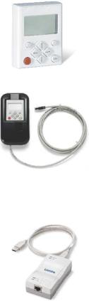
2 Introduction: Parameterising the controller
2.2Selection of the appropriate commissioning tool
_ _ _ _ _ _ _ _ _ _ _ _ _ _ _ _ _ _ _ _ _ _ _ _ _ _ _ _ _ _ _ _ _ _ _ _ _ _ _ _ _ _ _ _ _ _ _ _ _ _ _ _ _ _ _ _ _ _ _ _ _ _ _ _
2.2.1Overview: Accessories for commissioning
Version |
Features |
Product key |
|
Keypad X400 |
Quick access to parameters and operating data |
EZAEBK1001 |
|
|
• Supports hot plugging |
|
|
|
• Graphic display with plain texts |
|
|
|
• Backlighting |
|
|
|
• Easy user guidance |
|
|
|
• 4 navigation keys, 2 context-sensitive keys |
|
|
|
• Adjustable RUN/STOP function |
|
|
|
• Can be used for L-force Inverter Drives 8400 and Servo |
|
|
|
Drives 9400 |
|
|
Diagnosis terminal X400 |
Keypad X400 in a robust housing, also suitable for |
EZAEBK2001 |
|
|
installation into the control cabinet door. |
|
|
|
• Supports hot plugging |
|
|
|
• Graphic display with plain texts |
|
|
|
• Backlighting |
|
|
|
• Easy user guidance |
|
|
|
• 4 navigation keys, 2 context-sensitive keys |
|
|
|
• Adjustable RUN/STOP function |
|
|
|
• Incl. 2.5 m cable |
|
|
|
• Enclosure IP20; in case of front installation in control |
|
|
|
cabinet IP65 |
|
|
|
• Can be used for L-force Inverter Drives 8400 and Servo |
|
|
|
Drives 9400 |
|
|
USB diagnostic adapter |
For electrical isolation of your PC and the controller. |
E94AZCUS |
|
|
• Supports hot plugging |
|
|
|
• Diagnostic LED for data transfer display |
|
|
|
• plug and play |
|
|
|
• Input-side voltage supply via USB connection from PC |
|
|
|
• Output-side voltage supply via the diagnostic interface of |
|
|
|
the controller |
|
|
|
• Connecting cables can be selected in various lengths: |
|
|
|
|
|
|
Connecting cable for |
2.5 m length |
EWL0070 |
|
USB diagnostic adapter |
|
|
|
5 m length |
EWL0071 |
||
|
|||
|
|
|
|
|
10 m length |
EWL0072 |
|
|
|
|
26 |
Lenze · 8400 StateLine · Reference manual · DMS 12.0 EN · 06/2014 · TD05/TD14 |
2 Introduction: Parameterising the controller
2.3General notes on parameters
_ _ _ _ _ _ _ _ _ _ _ _ _ _ _ _ _ _ _ _ _ _ _ _ _ _ _ _ _ _ _ _ _ _ _ _ _ _ _ _ _ _ _ _ _ _ _ _ _ _ _ _ _ _ _ _ _ _ _ _ _ _ _ _
2.3General notes on parameters
All parameters for controller parameterising or monitoring are saved as so-called "codes".
•The codes are numbered and indicated by the prefix "C" before the code, e.g. "C00002".
•Moreover, each code has a name and specific attributes, as for example access type (reading, writing), data type, limit values and default setting ("Lenze setting").
•For the sake of clarity, some codes contain "subcodes" for saving parameters. This Manual uses a slash "/" as a separator between code and subcode, e.g. C00118/3".
•According to their functionality, the parameters are divided into three groups:
•Setting parameters: For specifying setpoints and for setting device / monitoring functions.
•Configuration parameters: For configuring signal connections and terminal assignments.
•Diagnostic/display parameters: For displaying device-internal process factors, current actual values and status messages. These are read-only parameters.
Lenze · 8400 StateLine · Reference manual · DMS 12.0 EN · 06/2014 · TD05/TD14 |
27 |

2 Introduction: Parameterising the controller
2.3General notes on parameters
_ _ _ _ _ _ _ _ _ _ _ _ _ _ _ _ _ _ _ _ _ _ _ _ _ _ _ _ _ _ _ _ _ _ _ _ _ _ _ _ _ _ _ _ _ _ _ _ _ _ _ _ _ _ _ _ _ _ _ _ _ _ _ _
2.3.1Changing the parameterisation with the keypad
The keypad is simply plugged on the diagnostic interface X6 ("DIAG") at the front of the standard device.
Plugging and unplugging the keypad is possible during operation.
Keypad display and control elements
|
/&' GLVSOD\ |
+HDGOLQH |
|
7ULSOH OLQH GLVSOD\ |
|
'HYLFH VWDWH |
|
&XUUHQW IXQFWLRQ |
&XUUHQW IXQFWLRQ |
OHIW IXQFWLRQ NH\ |
ULJKW IXQFWLRQ NH\ |
,Q PDQXDO FRQWURO PRGH |
WXST |
VYR |
,Q PDQXDO FRQWURO PRGH |
6WRS PRWRU |
|
|
6WDUW PRWRU |
LCD display
Headline
In the menu level: Menu name
In the parameter level: Parameter name
Three-part display
In the menu level: List of available menus
In the parameter level: Code/subcode and setting or actual value
Device status
|
Controller is switched on |
|
Pulse inhibit active |
|
|
|
|
|
Controller is enabled |
|
System fault active |
|
|
|
|
|
Controller is inhibited |
|
"Fault" device status is active |
|
|
|
|
|
Quick stop active |
|
"Trouble" device status is active |
|
|
|
|
|
Current limit exceeded |
|
"TroubleQSP" device status is active |
|
|
|
|
|
Speed controller 1 in the limitation |
|
A warning is indicated |
|
|
|
|
28 |
Lenze · 8400 StateLine · Reference manual · DMS 12.0 EN · 06/2014 · TD05/TD14 |
2 Introduction: Parameterising the controller
2.3General notes on parameters
_ _ _ _ _ _ _ _ _ _ _ _ _ _ _ _ _ _ _ _ _ _ _ _ _ _ _ _ _ _ _ _ _ _ _ _ _ _ _ _ _ _ _ _ _ _ _ _ _ _ _ _ _ _ _ _ _ _ _ _ _ _ _ _
LCD display
Function - left function key |
Function - right function key |
|
Change parameter setting |
|
Accept change in the controller |
(change to editing mode) |
|
(no saving with mains failure protection ) |
Back to main menu |
|
Abort (discard change) |
|
|
|
Parameter can only be changed when the controller is inhibited |
||
Save all parameter settings in the memory module safe against mains failure
Control elements
Execute the function assigned to the function key (see LCD display)
Execute the stop function set in C00469 (Lenze setting: Inhibit controller)
Deactivate stop function again (Lenze setting: Enable controller again)
In the menu level: Select menu/submenu |
|
|
In the parameter level: Select parameter |
In the editing mode: Change marked digits or select list entry |
|
In the menu level: Select submenu/change to parameter level In the editing mode: Cursor to the right
In the menu level: One menu level higher (if available) In the parameter level: Back to the menu level
In the editing mode: Cursor to the left
Menu structure
In the keypad, the parameters are classified into various menus and submenus.
•The USER menu includes a selection of frequently used parameters.
•The Code list contains all parameters.
•The Go to param function enables you to reach the corresponding parameter directly.
•The Logbook logs all errors and their chronological history.
•The Diagnostics menu contains diagnostic/display parameters for displaying device-internal process factors, current actual values and status messages.
Userlevel
From version 12.00.00 onwards, the extent of menus, submenus an codes shown in the keypad can be adapted by selecting the "Userlevel" in C00001/1:
•Userlevel Standard (Lenze setting): Only the most important menus and codes are shown in the keypad.
•Userlevel Expert: All menus and codes are shown in the keypad.
•Userlevel Service: For service purposes only (Lenze service).
The the Userlevel has been changed, the menus are restructured in the keypad according to the selected Userlevel. The parameters of a plugged in communication module are always displayed completely independent of the set Userlevel.
Lenze · 8400 StateLine · Reference manual · DMS 12.0 EN · 06/2014 · TD05/TD14 |
29 |
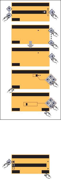
2 Introduction: Parameterising the controller
2.3General notes on parameters
_ _ _ _ _ _ _ _ _ _ _ _ _ _ _ _ _ _ _ _ _ _ _ _ _ _ _ _ _ _ _ _ _ _ _ _ _ _ _ _ _ _ _ _ _ _ _ _ _ _ _ _ _ _ _ _ _ _ _ _ _ _ _ _
General operation
|
Par1 8400 StateLine C |
1. Use the / navigation keys to select the |
||
1. |
desired menu. |
|||
|
|
|||
|
USER - Menu |
|
• Use the / navigation keys to reach a |
|
|
Code list |
|
||
|
|
higher/lower menu level. |
||
|
Go To Param |
|
||
|
|
|
||
|
SAVE |
|
• Use the function key to return to the |
|
|
|
|
main menu. |
|
|
Load Lenze setting |
2. |
2. Use the / navigation keys to select the |
|
|
C00002/001 |
|
parameter to be set within a submenu. |
|
|
|
|
||
|
Off / Finished |
|
3. In order to select another subcode in case of a |
|
|
EDIT |
|
parameter with subcodes: |
|
|
|
|
||
|
|
|
• Press the navigation key to change tot he |
|
|
Fixed setpoint 1 |
|
editing mode for the subcode. |
|
|
C00039/001 |
3. |
• Use the navigation keys to set the desired |
|
|
40.00 % |
|
subcode. |
|
|
|
|
||
|
EDIT |
|
4. Use the function key to switch over to the |
|
|
|
editing mode. |
||
|
|
|
||
|
Fixed setpoint 2 |
|
5. Use the navigation keys to set the desired value. |
|
|
C00039/002 |
|
6. Use the function key to accept the change |
|
|
|
|
||
|
60.00 % |
|
and to leave the editing mode. |
|
|
EDIT |
|
• Use the function key to leave the editing |
|
4. |
|
mode without accepting the change. |
||
|
|
|||
|
Fixed setpoint 2 |
|
|
|
|
C00039/002 |
5. |
|
|
|
60.00 % |
|
|
|
|
ESC |
OK |
|
|
6.
[2-2] Example: Changing parameters with the keypad
Multilingualism
All texts displayed in the keypad are in English.
From version 11.00.00 onwards, the most important menus as well as diagnostic and configuration parameters can are also available in German and French. To set a different language, select the Language selection menu item in the main menu of the keypad.
Language |
|
|
• The multilingual texts are stored in the |
|
|
controller and do not have to be loaded into the |
|
|
|
|
|
English |
|
|
device. |
|
|
||
Deutsch |
|
|
• For reasons of disc space, only the most |
Français |
|
|
|
|
|
||
ESC |
OK |
important menus and parameters as well as the |
|
|
|
|
error messages are available in several |
|
|
|
languages. |
|
|
|
|
30 |
Lenze · 8400 StateLine · Reference manual · DMS 12.0 EN · 06/2014 · TD05/TD14 |
Loading...