


 Loading...
|
|
|
|
© KROHNE 03/07 |
7026322100 |
|
|
Supplementary
Installation and Operating
Instructions
Optiflux IFC300 Converter with HART Interface
(Dev Rev 2, DD Rev 1)
•HART/Field Communicator 375
•Asset Management Solutions (AMS)
•Process Device Manager (PDM)
•Field Device Tool/Device Type Manager (FDT/DTM)
HART_Suppl_IFC300_V0201.DOC |
1/23 |
04/2007 |
|

Supplementary Handbook IFC 300 HART, FC375, AMS, PDM, DTM
|
|
|
|
|
1 |
General Information |
3 |
||
2 |
IDs and Revision numbers |
5 |
||
3 |
Inputs/Outputs and HART Dynamic/Transmitter Variables |
6 |
||
4 |
Basic Configuration Parameters |
7 |
||
5 |
Field Communicator 375 (FC375) |
7 |
||
|
5.1 |
Installation |
7 |
|
|
5.2 |
Operating |
7 |
|
6 |
Asset Management Solutions (AMS) |
7 |
||
|
6.1 |
Installation |
7 |
|
|
6.2 |
Operating |
7 |
|
7 |
Process Device Manager (PDM) |
8 |
||
|
7.1 |
Installation |
8 |
|
|
7.2 |
Operating |
8 |
|
8 |
Field Device Tool Device Type Manager (FDT DTM) |
8 |
||
|
8.1 |
Installation |
8 |
|
|
8.2 |
Operating |
8 |
|
9 |
Attachment: Menu Trees for FC375, AMS and PDM |
9 |
||
HART_Suppl_IFC300_V0201.DOC |
2/23 |
04/2007 |
|
Supplementary Handbook IFC 300 HART, FC375, AMS, PDM, DTM
1 General Information
The IFC 300 is a “four-wire” transmitter with 4...20mA current output and HART® capability. Dependent on jumper setting and/or wiring the current output can operate as active or passive output.
General characteristics of the IFC 300 HART® interface:
•Multidrop Mode is supported
•Burst Mode is not supported
Electrical connection: Refer to section “Electrical connection: outputs and inputs” of the following manual:
• “Handbook IFC 300 signal converter” (KROHNE)
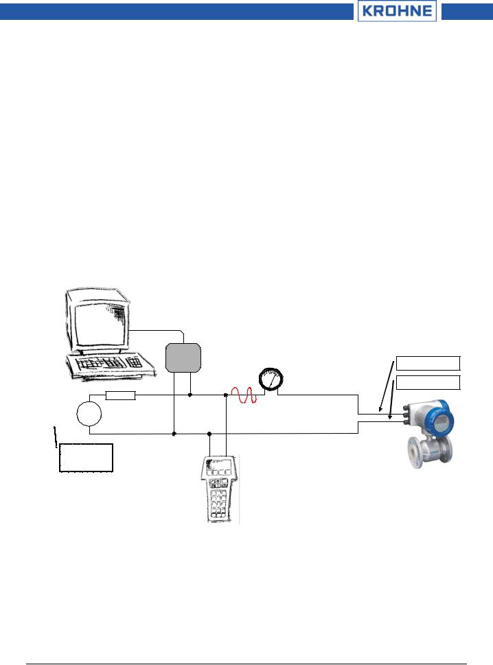
There are two ways of using the HART® communication:
a) As a point-to-point connection between the IFC 300 and the HART master equipment. The instrument's current output may be active or passive.
Point-to-Point Analog/Digital Mode
Primary Master
|
HART |
|
Analog |
|
|
|
Modem |
|
Terminal A (C) |
||
|
|
|
|
||
|
|
HART |
4 |
mA 20 |
Terminal A- (C-) |
|
|
|
|
||
Power |
≥ 250 Ω |
|
|
|
4...20 mA |
|
|
|
|
||
Supply |
|
|
|
|
|
|
|
|
|
|
|
For slaves with |
|
|
|
|
IFC 300 |
passive current |
|
|
|
|
Addr. 0 |
output (2 wire)
Secondary Master
HART_Suppl_IFC300_V0201.DOC |
3/23 |
04/2007 |
|

Supplementary Handbook IFC 300 HART, FC375, AMS, PDM, DTM
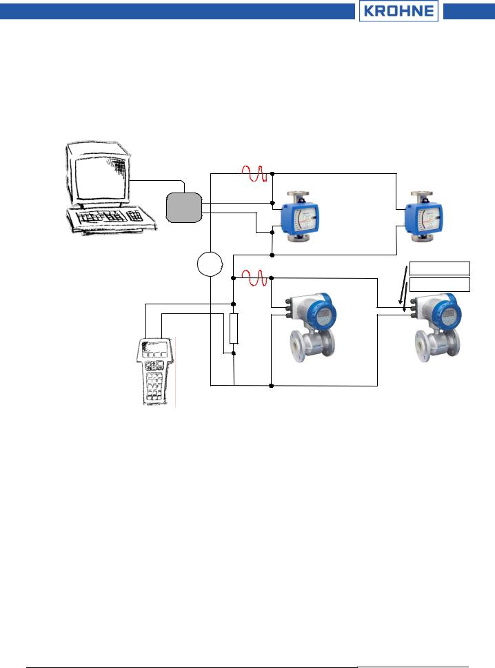
b) As a multipoint connection (multidrop) with up to 15 devices (IFC 300 or other HART® equipment) in parallel. The instrument's current outputs must be passive.
Multidrop Mode
Primary Master
|
HART |
|
|
Modem |
|
|
HART |
|
Power |
≥ 250 Ω |
|
|
|
|
Supply |
|
Terminal A (C) |
|
|
Terminal A- (C-) |
|
4 mA |
4 mA |
|
|
. . . |
|
Secondary Master |
Up to 15 |
|
|
Slaves |
|
|
. . . |
|
IFC 300 |
IFC 300 |
|
Addr. > 0 |
Addr. > 0 |
|
(passive current output) |
(passive current output) |
HART_Suppl_IFC300_V0201.DOC |
4/23 |
04/2007 |
|
Supplementary Handbook IFC 300 HART, FC375, AMS, PDM, DTM
In case the IFC 300's current output shall work continuously active a 'third wire' is needed to properly connect it together with two-wire loop powered devices in the same network.
Multidrop Mode (‘three-wire’)
(Connecting two-wire and four-wire devices in the same network)
Primary Master |
HART |
|
|
|
|
||
|
4 mA |
4 mA |
|
HART |
|
two-wire |
|
Modem |
|
loop powered |
|
|
|
devices |
|
|
|
. . . |
|
|
Addr. > 0 |
Addr. > 0 |
|
Power |
HART |
Terminal A (C) |
|
Supply |
|||
|
|||
|
4 mA |
4 mA Terminal A- (C-) |
|
|
|
four-wire |
|
|
|
active |
|
|
|
source |
|
|
≥ 250 Ω |
devices |
|
|
|
||
Secondary Master |
|
. . . |
|
|
IFC 300 |
||
|
Addr. > 0 |
IFC 300 |
|
|
Addr. > 0 |
||
|
|
2 IDs and Revision numbers
The HART Device Descriptions described in this document have the following IDs and revision numbers:
Manufacturer ID: |
69 (0x45) |
Device Type: |
227 (0xE3) |
Device Revision: |
2 |
DD Revision: |
1 |
HART Universal Revision: |
5 |
FC 375 System SW Rev.: |
≥ 1.8 |
AMS Version: |
≥ 6.0 |
PDM Version: |
≥ 6.0 |
For information about Transmitter Revisions and related Device Descriptions refer to the KROHNE HART Device List.
HART_Suppl_IFC300_V0201.DOC |
5/23 |
04/2007 |
|

Supplementary Handbook IFC 300 HART, FC375, AMS, PDM, DTM
3 Inputs/Outputs and HART Dynamic/Transmitter Variables
The IFC 300 is available with a choice of output/input assemblies (see details in the section "I/O assemblies for the outputs and inputs" of the “Handbook IFC 300 signal converter” (KROHNE)):
The assignment of the I/O terminals (A, B, C and D) to the HART Dynamic Variables (PV, SV, TV and FV) depends on the device's I/O option:
|
|
HART Dynamic Variables: |
|
|||
|
PV |
|
SV |
TV |
|
FV |
|
|
|
|
|
|
|
Basic I/O terminals: |
A |
|
D |
- |
|
- |
Modular I/O and |
C |
|
D |
A |
|
B |
EEx–i I/O terminals: |
|
|
||||
|
|
|
|
|
|
|
The IFC 300 transmitter handles up to 10 measurement-related HART Transmitter Variables but the sub-set of available variables depends on the device's I/O option and its configuration:
|
HART Transmitter |
|
Code1 |
Type |
Notes |
|
Variable |
|
|
|
|
|
Flow Speed |
|
20 |
Linear |
|
|
Volume Flow |
|
21 |
Linear |
|
|
Mass Flow |
|
22 |
Linear |
|
|
Conductivity |
|
24 |
Linear |
|
|
Coil Temperature |
|
23 |
Linear |
|
|
Counter 1 (C) |
|
6 |
Totaliser |
valid for Basic IO option only |
|
Counter 1 (B) |
|
13 |
Totaliser |
valid for Modular I/O and EEx–i I/O options only |
|
Counter 2 (D) |
|
14 |
Totaliser |
|
|
Counter 3 (A) |
|
12 |
Totaliser |
valid for Modular I/O and EEx–i I/O options only |
|
Diagnosis Value |
|
25 |
Linear |
function and validity depend on 'diagnosis value' |
|
|
|
|
|
setting (Fct. C1.3.17) |
1 HART Transmitter Variable Code |
|
|
|
||
To Dynamic Variables which are tied to linear analogue outputs (i.e. current outputs and frequency outputs) the HART Transmitter Variables are assigned by selecting the 'measurement' (Fct. C2.x.5) for these outputs. (E.g. when selecting the 'measurement' volume flow for current output A of a device with Basic IO the HART Transmitter Variable Volume Flow is assigned to the HART Dynamic Variable PV). This implies that only Transmitter Variables of linear type can be assigned to Dynamic Variables tied to current or frequency outputs. (A totaliser variable e.g. can't be assigned to PV, the HART current output)
For Dynamic Variables not tied to linear analogue outputs there is no such correlation: Both linear and totaliser type Transmitter Variables can be assigned (Fct. C4). (Therefore a totaliser variable e.g. can be assigned to SV, TV and FV unless the respective output is a current or frequency output.)
HART_Suppl_IFC300_V0201.DOC |
6/23 |
04/2007 |
|

Supplementary Handbook IFC 300 HART, FC375, AMS, PDM, DTM
4 Basic Configuration Parameters
There are some parameters (namely measurement counter 1..3 and diagnosis value selection) which, after they have been changed, require a warm start of the device e.g. for updating dependent units parameters, before any other parameters may be written. Dependent on the characteristics and capabilities of the HART host system (e.g. online-/offline-orientation) these parameters are treated differently (see details below).
5 Field Communicator 375 (FC375)
5.1 Installation
The IFC 300 HART Device Description has to be installed on the FC375 respectively. Otherwise the user will work with the instrument as a generic one thus loosing opportunity for entire instrument control.
For installing DDs on the FC375 the ‘Easy Upgrade Programming Utility’ is needed and the FC375 must have a System Card with ‘Easy Upgrade’ option (see details in the ‘375 Field Communicator User’s Manual’).
5.2 Operating
Refer to the IFC 300 Menu Tree FC375 (Attachment A).
The IFC 300 operation via FC375 is made quite close to the manual instrument control via keypad with the restriction that parameters of the device's "service" menu are not supported and simulation is possible only for current outputs. The online help of each parameter contains its function number as a reference to the device’s local display and the “Handbook”.
Parameter protection for custody transfer is the same as on the device's local display. Other specific protection mechanisms like "password quick setup" and "password setup" are not supported via HART. The FC375 always creates a “full” configuration for interaction with AMS. Still the FC375 considers only a partial parameter set (like the “standard configuration” in the HART Communicator HC275) when sending it to a device.
Basic Configuration Parameters:
In online mode the counter measurement and diagnosis value settings can be changed with the corresponding methods located in the menu tree below the related parameter. When editing an offline configuration these parameters are read only, however they are written to the device when sending an offline configuration
6 Asset Management Solutions (AMS)
6.1 Installation
If the IFC 300 Device Description is not already installed on the AMS System a so called Installation Kit IFC 300 HART AMS is needed (available as download from KROHNE ‘Download Center’ on the internet or on floppy disk / CD-ROM from KROHNE).
For installing the DD with the Installation Kit refer to the “AMS Intelligent Device Manager Books Online" section "Basic AMS Functionality /Device Configurations / Installing Device Types / Procedures /Install device types from media”. Please read also the “readme.txt”, which is also contained in the Installation Kit.
6.2 Operating
Refer to the IFC 300 Menu Tree AMS (Attachment B).
Due to AMS requirements and conventions the IFC 300 operation differs to some extent from operation with FC375 and via local keypad. Furthermore parameters of the device's "service" menu are not supported and simulation is possible only for current outputs. The online help of each parameter contains its function number as a reference to the device’s local display and the “Handbook”.
Parameter protection for custody transfer is the same as on the device's local display. Other specific protection mechanisms like "password quick setup" and "password setup" are not supported via HART. Basic Configuration Parameters:
HART_Suppl_IFC300_V0201.DOC |
7/23 |
04/2007 |
|
Loading...