

Page 1
© KROHNE 09/2003
Supplementary
Installation and Operating
Instructions
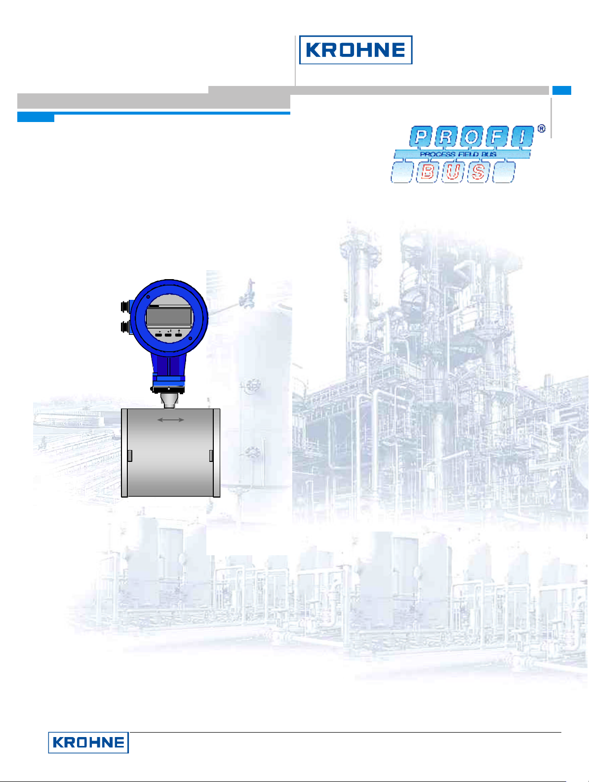
UFC030 (UFC 3 Beam)
KROHNE
1 2 3 4 5 6
KROHNE Messtechnik GmbH & Co. KG · Ludwig-Krohne-Str. 5 D-47058 Duisburg 1/7
Tel.: 0203-301 309 Fax: 0203-301389 · e-mail: [email protected]
Page 2

Supplementary documentation UFC030 with PROFI BUS-PA
CONTENTS:
1 GENERAL...................................................................................................................................................................................................3
2 ITEMS INCLUDED WITH SUPPLY.................................................................................................................................................3
3 SOFTWARE HISTORY..........................................................................................................................................................................3
4 PROFIBUS -PA...........................................................................................................................................................................................3
4.1 PROFILES.................................................................................................................................................................................................4
4.2 SERVICES.................................................................................................................................................................................................4
4.3 GSD FILES...............................................................................................................................................................................................4
4.3.1 Manufacturer specific GSD file: KROHF501.GSD........................................................................................................................4
4.3.2 Profile specific GSD file: PA_9741.GSD .........................................................................................................................................6
4.4 CYCLIC DATA EXCHANGE .....................................................................................................................................................................6
4.5 DATA S TRUCTURE OF FUNCTION BLOCK OUTPUT VALUES............................................................................................................6
4.5.1 Float Value .............................................................................................................................................................................................6
4.5.2 Status Value............................................................................................................................................................................................7
4.6 DIAGNOSIS...............................................................................................................................................................................................8
5 ELECTRICAL CONNECTION............................................................................................................................................................8
5.1 INTERCONNECTION OF DEVICES IN THE HAZARDOUS AREA.............................................................................................................8
5.2 BUS CABLE ..............................................................................................................................................................................................8
5.3 SHIELDING AND GROUNDI NG................................................................................................................................................................8
5.4 PROFIBUS-PA CONNECTION ..............................................................................................................................................................9
6 MENU SETTINGS FOR PROFIBUS -PA ..........................................................................................................................................9
7 IMPORTANT NOTES.............................................................................................................................................................................9
7.1 PARAMETER “METER_TYPE” OF UFC030...........................................................................................................................................9
8 TECHNICAL DATA ................................................................................................................................................................................10
9 DEVICE DESCRIPTION FOR THE SIMATIC PROCESS DEVICE MANAGER (PDM)...............................................11
9.1 INSTALLATION........................................................................................................................................................................................11
9.2 OPERATING..............................................................................................................................................................................................11
KROHNE Messtechnik GmbH & Co. KG · Ludwig-Krohne-Str. 5 D-47058 Duisburg 2/17
Tel.: 0203-301 309 Fax: 0203-301389 · e-mail: [email protected]
Page 3
Supplementary documentation UFC030 with PROFI BUS-PA
1 General
These Instructions are supplementary to the ”Installation and Operating Instructions (Reference Manual) UFC030
(UFC 3 Beam)”. The details given there, in particular the Safety Information, are valid and should be observed. These
Supplementary Instructions provide only additional information for device operation and connection to a PROFIBUSPA fieldbus.
2 Items included with supply
In addition to the standard scope of supply, these Supplementary Instructions for the UFC030 with PROFIBUS -PA
interface plus a diskette containing all PROFIBUS device data fi les (GSD files) available of all KROHNE devices will
be included.
3 Software history
Issued
Signal converter User program Instructions
month/year Hardware Firmware Hardware Operating
system
10/03 PROFIBUS-PA
Module+Device
MOD3 /031010 PC Windows 95,
98, NT 4.0,
ME, 2000
4 PROFIBUS-PA
Engineering or operation
Control system (PLC)
Class 1 master
PROFIBUS-DP, up to 12 Mbit/s
Analog I/O module
4-20 mA
HART device
control tool
Class 2 master
Power
Supply
Segment
coupler/link
PROFIBUS-PA
KROHNE
1 2 3 4 5 6
Software Device User program
PDM ≥ V 5.2
Segment
coupler/link
PROFIBUS-PA
KROHNE
1 2 3 4 5 6
1000
kg/h
03687 2
kg
900
800
KROHNEH250
700
600
SN 586 677/01-03MC H250/RR/M9/K2/ESK-Z
C K25.2 1.4571
500
F CIV 25 1.4571MD 1997
400
C2H50H
D 0.93 kg/l
300
V 2.5 mPa.sT 23.5 C
200
P 0.4 MPa
100RP
FIA 1025
-- --
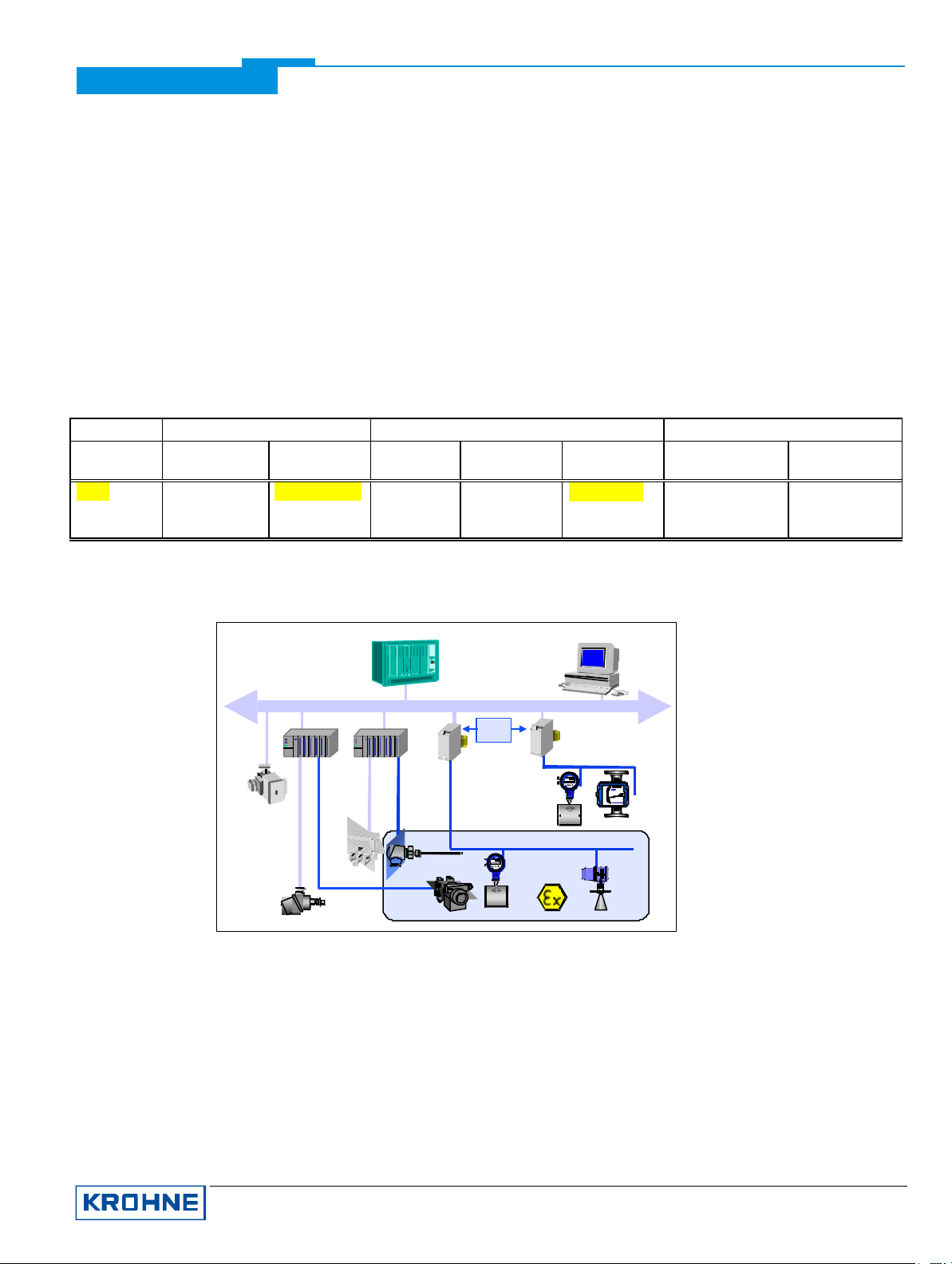
The diagram above shows a typical instrumentation with PROFIBUS -PA devices in hazardous and non-hazardous
locations, including connections of conventio nal devices (e.g. with 4-20mA signals) to the PROFIBUS-PA.
The PROFIBUS-PA is normally connected to a segment coupler which, among other things, carries out the
conversion to the PROFIBUS -DP. Here, it needs to be noted in particular that the segment coupler is normally set to
a fixed baud rate on the DP side.
Further information on the planning and operation of PROFIBUS-PA networks is to be found in the KROHNE
brochure ”PROFIBUS -PA Networks”.
KROHNE Messtechnik GmbH & Co. KG · Ludwig-Krohne-Str. 5 D-47058 Duisburg 3/17
Tel.: 0203-301 309 Fax: 0203-301389 · e-mail: [email protected]
Page 4

Supplementary documentation UFC030 with PROFI BUS-PA
4.1 Profiles
The UFC030 (UFC 3 Beam) supports the PROFIBUS-PA Profile Version 3.0. Additionally, all relevant parameters of
the device are accessible via the PROFIBUS -PA interface (if the manufacturer specific Ident-no is chosen and the
manufacturer specific GSD-file version is used).
The UFC030 (UFC 3 Beam) defines the following blocks:
• One physical block.
This block contains the parameters defined in Profile 3.0.
• One transducer block for ultrasonic flow meter devices.
This block provides the parameters and functions defined in Profile 3.0. Attached you will find here all the values
not defined by the profile.
• Three “Analog Input (AI)” function blocks: “Volume Flow”, “Speed of Sound” and “CORR. Volume Flow or HEAT
Flow (depends on the current device type selection)”.
• Two “Totalizer (TOT)” function blocks: totalized “Volume” and totalized “CORR. Volume or HEAT (depends on
the current device type selection)”.
4.2 Services
The UFC030 supports the following PROFIBUS -PA services being defined in the PROFIBUS-PA Profile V3.0:
1. DDLM_Set_Slave_Add
2. DDLM_Get_Cfg
3. DDLM_Set_Prm
4. DDLM_Chk_Cfg
5. DDLM_Slave_Diag
6. DDLM_Data_Exchange
The services mentioned above will enable the customer to set the PROFIBUS -PA station address (1), to configure
the data telegram for the cyclic data exchange (3/4), to read back the current PROFIBUS -PA configuration (2) and to
read the current Diagnostic data (5).
The service “cyclic data exchange” (6) will be used to transmit the function block output values (measurement data)
to a master.
4.3 GSD Files
All available GSD files of KROHNE devices – including those of UFC030 (UFC 3 Beam), of course - are supplied
together with each device. The GSD file contains information that will be needed for project planning of the
PROFIBUS-DP/PA communication network. The relevant data files must be loaded into the project planning
system/master system before start -up of the bus system.
The UFC030 (UFC 3 Beam) is supporting the entire PROFIBUS -PA profile V 3.0. The device has two Ident-no.
and two GSD files:
• Ident-no. “F501” belongs to the GSD file KROHF501.GSD and includes the complete functionality of the
ultrasonic flow meter.
• The application of the manufacturer independent Ident-no. “9741” (GSD file “PA_9741.GSD”) provides
interchangeability of devices, i.e. an exchange of mass flow meters of different vendors.
Please follow the instructions in the manual of the host supplier when installing the GSD File (KROHF501.GSD,
UFC3_B_n.bmp, UFC3_B_n.dib) into the PLC.
4.3.1 Manufacturer specific GSD file: KROHF501.GSD
KROHNE Messtechnik GmbH & Co. KG · Ludwig-Krohne-Str. 5 D-47058 Duisburg 4/17
Tel.: 0203-301 309 Fax: 0203-301389 · e-mail: [email protected]
Page 5
Supplementary documentation UFC030 with PROFI BUS-PA
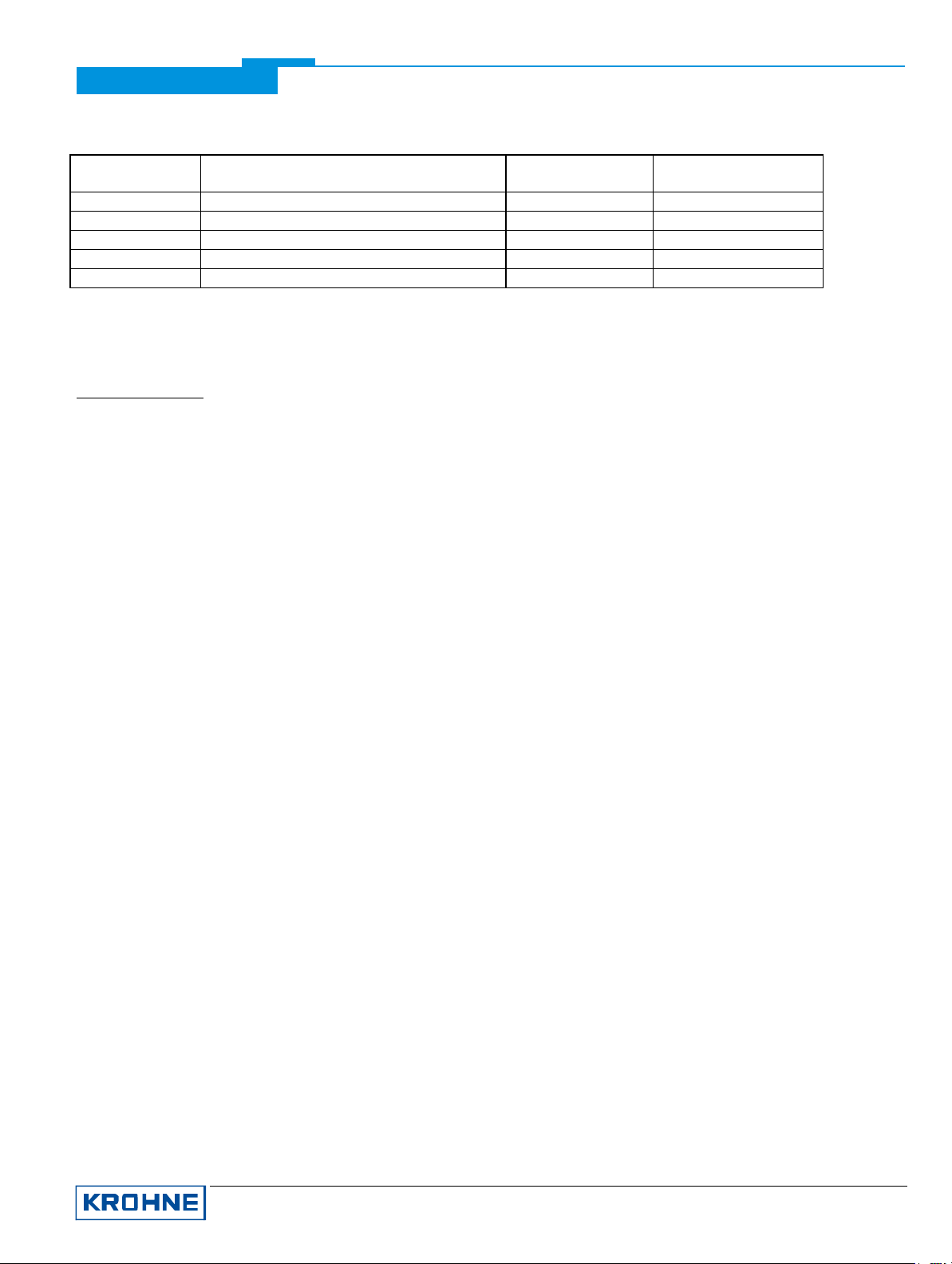
KROHNE delivers the GSD files with the entire device functionality, which is listed below:
Block Number Standard-Configuration
(function block output value)
KROHF701.GSD
Ident-No. F701
1 Volume Flow AI-FB
2 Speed of Sound AI-FB
3 Volume Totalizer Totalizer-FB
4 CORR. Volume Flow or HEAT Flow * AI-FB
5 CORR. Volume- or HEAT- Totalizer * Totalizer-FB
AI = Analog Input Function Block
FB = Function Block
• = depends on the current device type selection
Important Notes:
1. To project the PROFIBUS communication network you have to allocate each block to a function. On the PC-S7
from Siemens this will be done with the Tool named “HW - Config”. This tool offers the functions described as
follows:
2. It is possible to program an “Empty” block (the code of an “Empty” block is defined as 0x00) on each block
number. This means, that for this block no data are transmitted in the cyclic data telegram.
3. There is NO “Totalizer (TOT)” function block allowed on block position 1, 2 and 4! A “Analog Input (AI)” func tion
block or a “Empty” block is allowed here only! That means a “Totalizer (TOT)” function block is not possible at
this positions.
Note: All codes of “Analog Input (AI)” - and “Totalizer (TOT)” – function blocks valid for use will be find in the
corresponding GSD files.
4. There is NO “Analog Input (AI)” function block allowed on block position 3 and 5! A “Totalizer (TOT)” function
block or a “Empty” block is allowed here only! That means a “Analog Input (AI)” function block is not possible at
this positions.
5. There is a choice of 4 different totalizer functions, which can be allocated to the blocks 3 and / or 5. The 4
functions are defined as follows:
Function “Totalizer” cyclic transfer of the totalizer with status to the master
Function “SetTot_Total” cyclic transfer of the totalizer with status to the master + cyclic control data
from master to the device via the Bytes SetTot
Function “ModeTot_Total” cyclic transfer of the totalizer with status to the master + cyclic control data
from master to the device via the Bytes ModeTot
Function “SetTot_ModeTot_Total” cyclic transfer of the totalizer with status to the master + cyclic control data
from master to the device via the Bytes SetTot and after that ModeTot
Both, the Byte SetTot and ModeTot are being sent cyclical from the Master to the device if these bytes are
inserted as output data via the to the PLC configurator. The meaning of these control bytes are as follows:
SetTot:
SetTot =0: Totalizer is totalizing.
SetTot =1: Totalizer will be reset to 0 and stays at 0 until SetTot is switched back again to 0. If the value of
SetTot changes from “1” to “0” the totalizer starts counting from 0.
SetTot =2: Totalizer is set to the value defined by PresetTot. PresetTot can be written via a acyclic master
(totalizer in block 3 = Slot 3 Index 32; totalizer in block 5 = Slot 5 Index 32).If the value of SetTot
changes from “1” to “0” the totalizer starts counting from the current value defined by PresetTot.
SetTot > 2: not allowed
ModeTot:
ModeTot = 0 totalizer totalizes positive and negative values.
KROHNE Messtechnik GmbH & Co. KG · Ludwig-Krohne-Str. 5 D-47058 Duisburg 5/17
Tel.: 0203-301 309 Fax: 0203-301389 · e-mail: [email protected]
Page 6
VZ
Supplementary documentation UFC030 with PROFI BUS-PA
ModeTot = 1 totalizes only positive values.
ModeTot = 2 totalizes only negative values.
ModeTot = 3 totalizer is stopped, no totalization will be done.
ModeTot > 3 not allowed
6. The standard block configuration may be changed by the customer but using the default settings is highly
recommended. If the standard block configuration should be changed by the customer a acyclic master tool
must be used to change the “channel parameter” value of the block which should be connected to another
transducer output value.
4.3.2 Profile specific GSD file: PA_9741.GSD
The functionality of the profile specific GSD file is limited. This GSD file includes only three blocks:
Volume Flow, Speed of Sound (Sound Velocity) and Volume Flow totalizer.
You need the PA_9741 file to use this functionality. Before this, the communication has to be projected and it has to
be switched from “full functionality” to “interchangeable basic configuration” by using a master class 2 tool
(IDENT_NUMBER_SELECTOR: Slot 0, Index 40 change byte value from 1 to 0). After this has been done, the
device has to be projected by using the PA _9741 file.
4.4 Cyclic data exchange
During network configuration the user has to define which function block outputs of the UFC030 (UFC 3 Beam)
should be transferred cyclically to the master. The following function block outputs are available in this order:
1. Volume Flow and Status
2. Speed of Sound und Status
3. Volume Totalizer and Status
4. CORR. Volume Flow or HEAT Flow * and Status
5. CORR. Volume- or HEAT- Totalizer * and Status
• depends on the current device type selection
Note: If a function block output is chosen for cyclical data transfer the value "Not_a_Number" (0x7FFFFFFF) will be transmitted if the
function block itself is not available (due to the current device type selection). If so the status is "Bad-Out of Service".
Network configuration will be done by a master class 2 tool using one of the GSD files described above. The function
block outputs which should be transmitted cyclically may be chosen without any restriction. The order of transmission
always remains the same even if a function block is defined as an “Empty” block (if so no function block output data
will be send to the master and all function block outputs following the “Empty” block will move up one position).
4.5 Data Structure of Function Block Output Values
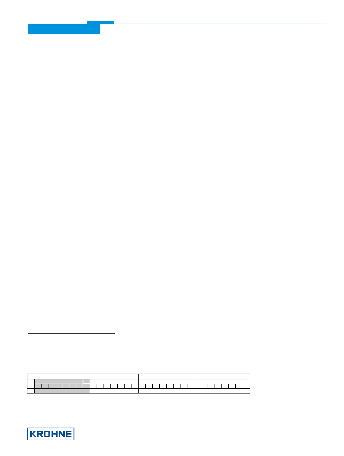
The data structure of function block outputs consists of 5 bytes: a 4 byte float value (Float Format according IEEE
Standard 754 Short Real Number) followed by a 1 byte status value. If all 5 function block outputs have been
projected (see above), 25 byte will be transmitted.
4.5.1 Float Value
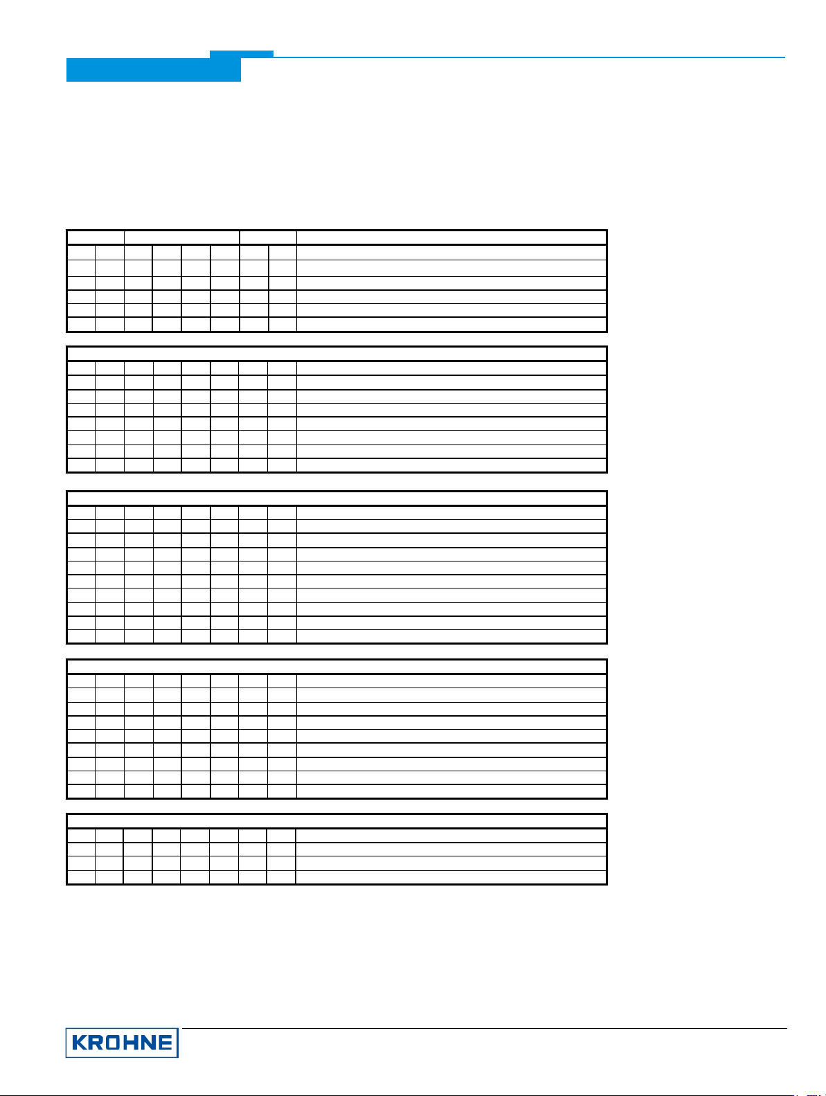
First an example of the float format:
Bit7
Exponent Mantisse Mantisse Mantisse
Example: 40 F0 00 00 (hex) = 0100 0000 1111 0000 0000 0000 0000 000 0 (binary)
Formula: Value = (-1)
Byte n Byte n+1 Byte n+2 Byte n+3
Bit6
7
6
5
4
2
2
3
2
2
2
Bit7
2
2
Bit6
1
0
-1
-2
-3
-4
2
2
2
2
VZ
2
2
* 2
-5
2
(Exponent - 127)
Bit7
-6
-7
-8
-9
-10
-11
-12
2
2
2
2
2
-13
2
2
2
Bit7
-14
-152-162-172-182-192-202-212-22
2
2
* (1 + Mantisse)
-23
2
KROHNE Messtechnik GmbH & Co. KG · Ludwig-Krohne-Str. 5 D-47058 Duisburg 6/17
Tel.: 0203-301 309 Fax: 0203-301389 · e-mail: [email protected]
Page 7
Supplementary documentation UFC030 with PROFI BUS-PA
Value = (-1)
0
* 2
(129 - 127)
* (1 + 2-1 + 2-2 + 2-3)
Value = 1 * 4 * (1 + 0,5 + 0,25 + 0,125)
Value = 7,5
4.5.2 Status Value
You will find the meaning of the status byte (unsigned integer) by looking at the tables down below:
Quality Quality-Substatus Limits
Gr Gr QS QS QS QS Qu Qu
27 26 25 24 23 22 21 20
0 0 = bad
0 1 = uncertain
1 0 = good (Non Cascade)
1 1 = good (Cascade) - not supported
Status = bad
0 0 0 0 0 0 = non-specific
0 0 0 0 0 1 = configuration error
0 0 0 0 1 0 = not connected
0 0 0 0 1 1 = device failure
0 0 0 1 0 0 = sensor failure
0 0 0 1 0 1 = no communication (last usable value)
0 0 0 1 1 0 = no communication (no usable value)
0 0 0 1 1 1 = out of service
Status = uncertain
0 1 0 0 0 0 = non-specific
0 1 0 0 0 1 = last usable value
0 1 0 0 1 0 = substitute-set
0 1 0 0 1 1 = initial value
0 1 0 1 0 0 = sensor conversion not accurate
0 1 0 1 0 1 = engineering unit violation (unit not in the valid set)
0 1 0 1 1 0 = sub-normal
0 1 0 1 1 1 = configuration error
0 1 1 0 0 0 = simulated value
0 1 1 0 0 1 = sensor calibration
Status = good (Non-Cascade)
1 0 0 0 0 0 = ok
1 0 0 0 0 1 = update event
1 0 0 0 1 0 = active advisory alarm (priority < 8)
1 0 0 0 1 1 = active critical alarm (priority > 8)
1 0 0 1 0 0 = unacknowledged update event
1 0 0 1 0 1 = unacknowledged advisory alarm
1 0 0 1 1 0 = unacknowledged critical alarm
1 0 1 0 0 0 = initiate fail safe
1 0 1 0 0 1 = maintenance required
Status = Limits
0 0 = ok
0 1 = low limited
1 0 = high limited
1 1 = constant
Check the first two quality bits in order to get the quality information of the measurement value:
Good (non Cascade) function block output value is ok and can be used without restrictions
Good (Cascade) will not be supported, because it is not applicable for the device
Uncertain function block output value can be used but the accuracy can not be guaranteed (e.g. function
block outputs value has been frozen or A/D converter is saturated or out of range)
Bad function block output value is bad don´t use it!
KROHNE Messtechnik GmbH & Co. KG · Ludwig-Krohne-Str. 5 D-47058 Duisburg 7/17
Tel.: 0203-301 309 Fax: 0203-301389 · e-mail: [email protected]
Page 8

Supplementary documentation UFC030 with PROFI BUS-PA
The „Quality-Substatus“- and „Limit“-Bits will be used for further diagnostics or limit checking.
Attention: The status should be watched always because a valid number will be transmitted even if the status of
the measurement value is bad or uncertain. This is the only way to check the meaning of the
transmitted measurement values.
4.6 Diagnosis
If the device internal diagnostic functions will detect an error additional information will be send to the Master (for
further information have a look at the UNIT_DIAG_BIT(i) definitions of the corresponding GSD-file)
5 Electrical Connection
For a detailed description please check the Installation and Operating Instructions manual of the device.
5.1 Interconnection of devices in the hazardous area
A PROFIBUS -PA network in the hazardous area should be projected in accordance with actual regulations:
• all electrical components which should be connected to the bus must be approved according the hazardous area
regulations,
• the approved input values of the field devices (Uo, Io, Po) must match with the output values of the power supply
(e.g. segment coupler) which means Ui ≤ Uo, Ii ≤ Io and Pi ≤ Po.
• the maximum length of each trunk cable does not exceed 1000 m,
• the maximum length of each spur cable does not exceed 30 m,
• the values of the cable are within the following ranges R´=15...150Ω/km; L´=0,4...1mH/km; C´=80...200nF/km,
5.2 Bus cable
Cable length between any devices should be less then 1900 m. Further limitations to the cable than the hazardous
area limitations are not existent. Nevertheless a twisted pair and overall shielded cable is strongly recommended. A
good quality cable could have the following data (Type A):
impedance at 31.25 kHz
DC resistance (per conductor)
capacity unbalanced < 2 nF/km
attenuation at 39 kHz < 3,0 dB
5.3 Shielding and grounding
For an optimum electromagnetic compatibility of systems it is extremely important that the system
components and particularly the bus cables connecting the components be shielded. This shields should be
connected in a way that they will look like “one non interrupted, unbroken shield” (if possible).
Hence it follows that, for use in non-hazardous duty systems , the cable shield should be grounded as often
as possible.
In “Ex“ systems with adequate equipotential bonding in the hazardous and non-hazardous location along
the entire fieldbus installation, multiple grounding of the shield is also of advantage.
Note: The use of twisted and shielded cables is strongly recommended, otherwise EMC protection of the
ultrasonic flow meter cannot be assured.
100 Ω ±20 %
22 Ω/km
KROHNE Messtechnik GmbH & Co. KG · Ludwig-Krohne-Str. 5 D-47058 Duisburg 8/17
Tel.: 0203-301 309 Fax: 0203-301389 · e-mail: [email protected]
Page 9
connected to the device by connecting it to PE
Supplementary documentation UFC030 with PROFI BUS-PA
5.4 PROFIBUS-PA connection
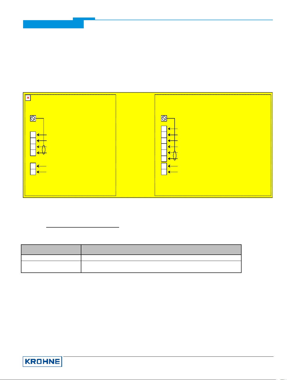
Connect the bus cable as shown in the figure.
• Connect the cable cores to the terminals
described as PA+ and PA-.
• Polarity reversal will not have any effect.
PE PE
• The cable shield should be connected with
minimum length to the PE functional ground.
• The equipotential bonding conductor must be
functional ground
II+
D +
D -
L
N
Device Model:
EX-modis Version 1 / 2
}
}
}
Current / Puls Output
(optional, no communication)
PROFIBUS-PA Interface
UFC5000 Power Supply
GND
A1
A2
l / C / P
D +
D -
L
N
Device Model:
Aqua-sonic 2
Circuit Ground
}
Analog Input 2
}
Analog Input 1
}
Puls- / Current-Outp. / Digital Inp.
}
(optional, no communication)
}
PROFIBUS-PA Interface
}
UFC5000 Power Supply
6 Menu Settings for PROFIBUS-PA
For a detailed description please check the Installation and Operating Instructions manual of the device. The
following settings should be done before the UFC030 (UFC 3 Beam) will be connected with the PROFIBUSPA network. Note that the address can be also set by using the communication service “Set slave address”
via the master tool.
Function (Fct.) Description
3.9.1 PROTOCOL
3.9.3 PR/FF ADDR
The PROFIBUS address can be changed via the PROFIBUS ser vice “Set_Slave_Address”. The input range is
0...125 according to the PROFIBUS specification. Address 126 is the default address and cannot be set via the
PROFIBUS-PA service “set_slave_add”.
• PROFIB PA
• Set address
Range: 000 - 126 for PROFIBUS-PA (default 126)
7 Important Notes
7.1 Parameter “meter_type” of UFC030
If “meter_type” will be changed by a service technician the below mentioned procedure must be carried out
step by step to avoid UFC030 malfunctions depending on an inconsistent data set of the PROFIBUS-PA
module.
KROHNE Messtechnik GmbH & Co. KG · Ludwig-Krohne-Str. 5 D-47058 Duisburg 9/17
Tel.: 0203-301 309 Fax: 0203-301389 · e-mail: [email protected]
Page 10
Supplementary documentation UFC030 with PROFI BUS-PA
1. UFC030 (Converter) data set must be reset to factory values first (Menu: 5.1.1 -> FACT PARAM)
2. “meter_type” must be changed into the device type required
3. UFC030 (Converter) data set must be saved again as factory values
4. A factory reset (factory reset = 1 / cold start) must be carried out via PDM (or any other PROFIBUS -PA
Master Tool available) to guarantee a consistent data set of both units (UFC030 converter and
UFC030 PROFIBUS-PA module)
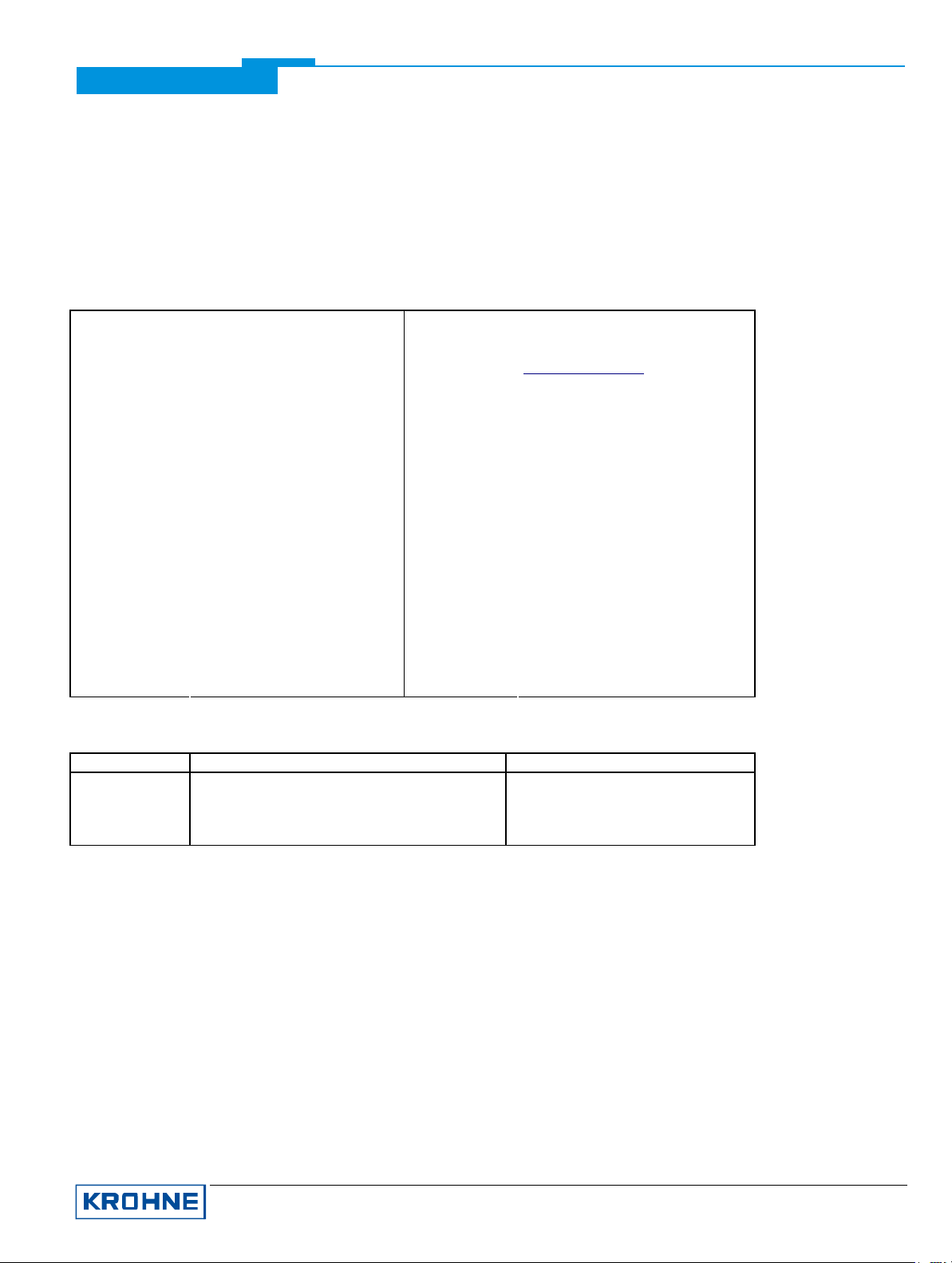
8 Technical Data
Hardware Software
Physical IEC 61158-2; 31,25kbit/s;
Connection independent of polarity Device profile Profile compact class B, V3.0
Base current 10,5 mA Address range 0...126; default 126
FDE
voltage mode
yes: separate fault
disconnection electronics
GSD GSD file supplied on diskette or at
http://www.krohne.de
0 to 125 via “set_slave_add”
0 to 126 via “Local Display”
(Fct. 3.9.1 & 3.9.3)
Operator control local display and operator interface at
device.
provided
Fault current 6 mA; (fault current = max.
continuous current – base current).
Starting current lower than the base current
“Ex“ approval EEx ia IIC T6 or EEx ib IIC/IIB T6,
details see manual
SAP’s 3; the number of Service Access Points
is typically equal of the maximum
number of master class 2 (operating)
tools
Function Blocks 1 PB
1 TB
3 AI
2 TOT
Possible function block outputs [default unit]:
Analog Input Totalizer
default
configuration
* depends on current device type
FB1: volume flow [m3/h]
FB2: speed of sound [m/s]
FB4: corr. volume flow [m3/h] or heat flow [MJ/s]*
FB3: volume totalizer [m3]
FB5: corr. volume totalizer [m3] or
heat totalizer [MJ]*
KROHNE Messtechnik GmbH & Co. KG · Ludwig-Krohne-Str. 5 D-47058 Duisburg 10/17
Tel.: 0203-301 309 Fax: 0203-301389 · e-mail: [email protected]
Page 11

Supplementary documentation UFC030 with PROFI BUS-PA
9 Device Description for the SIMATIC Process Device Manager (PDM)
9.1 Installation
If the UFC 030 Device Description is not already installed on the PDM System a so called Device Install is needed
(available on floppy disk from KROHNE or as download from KROHNE internet page).
For installing the DD with the Device Install refer to the “PDM Manual” section ”Utilities” / “Device Install". Please read
also the “readme.txt”, which is contained in the Device Install.
9.2 Operating
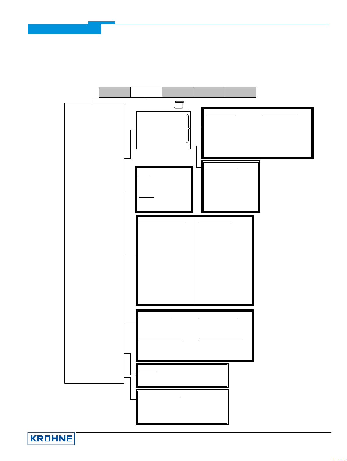
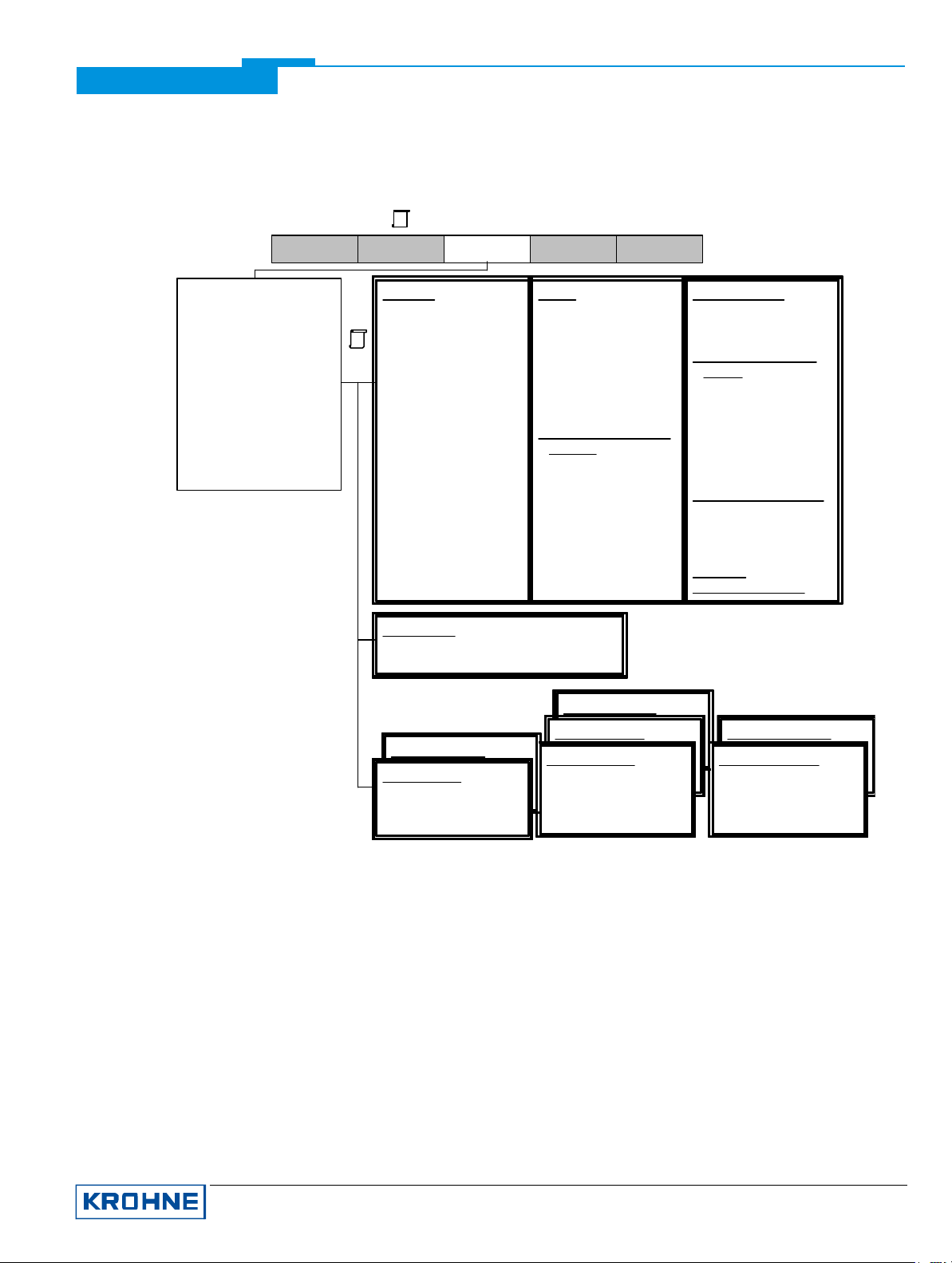
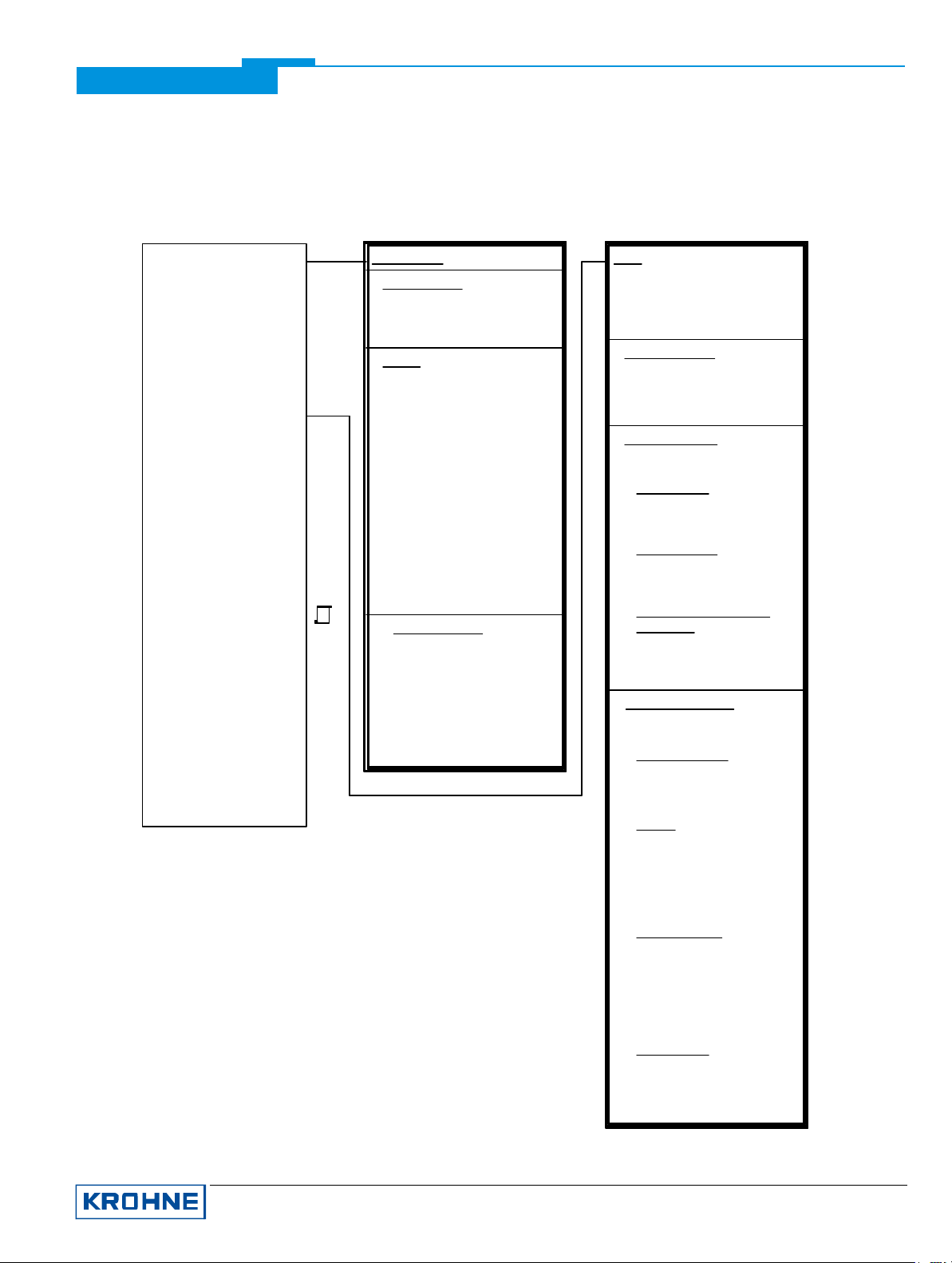
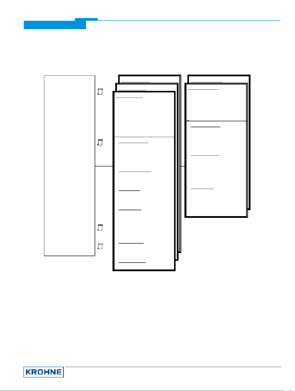
Refer to the UFC 030 Menu Tree PDM (Attachment A).
Due to PROFIBUS and PDM requirements and conventions the UFC 030 operation differs from operation via local
keypad and the following peculiarities should be kept in mind:.
• The online help of each parameter contains its function number as a reference to the device’s local display and
the “Installation and Operating Instructions”.
• If the device is operated via its local keypad no write operation can be performed via the PROFIBUS interface at
the same time. Please check in case the flag ’Device is controlled via its keypad’ in ‘View / Details / Signal
Converter State’.
• There are several complex dependencies between the parameters of the UFC 030. These dependencies can’t
be handled correctly to the full extent in the online dialogs of the PDM parameter table. Therefore it is
recommendable to switch these dialogs for the parameter table off. (See menu ‘Options / Customize / Table /
online dialog in the table available’).
• In order to find out whether the setting of the device is still the same as the parameter set stored in PDM
compare the ‘Static Revision No.’ of the respective PROFIBUS Block. (The current Static Revision No. is
displayed on the window ‘View / Device Status / <block name>’).
KROHNE Messtechnik GmbH & Co. KG · Ludwig-Krohne-Str. 5 D-47058 Duisburg 11/17
Tel.: 0203-301 309 Fax: 0203-301389 · e-mail: [email protected]
Page 12
Supplementary documentation UFC030 with PROFI BUS-PA
Attachment A
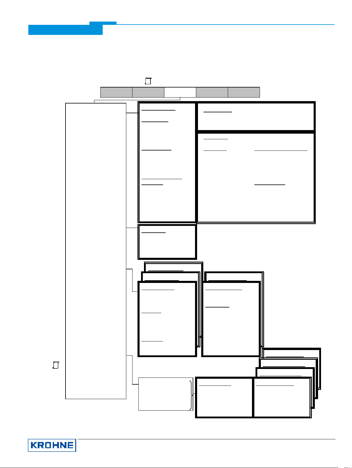
UFC030 Menu Tree PDM
Menu Bar
File Device View Options Help
Communication Path
----------------------------------Set Address
----------------------------------Load To Device
Load To PG/PC
-----------------------------------
Simulation
Test
-----------------------------------
Reset
-----------------------------------
2,3
FB1: AI-channel
FB2: AI-channel
FB3: TOT-channel
FB4: AI-channel
FB5: TOT-channel
Opt
Opt
Signal Converter
Inputs
• <Test Analog Inputs>
• <Test Digital Input>
Opt
Outputs
• <Test Current O.>
Opt
• <Test Frequency O.>
Communication Module
• <Factory Reset>
• <Warm Start>
• <Reset Address to 126>
FB3: TOT - channel
• <Reset Totalizer>
• <Preset Totalizer>
• <Start Totalizer>
• <Reset Status>
FB5: TOT - channel
Opt
Opt
• <Reset Totalizer>
• <Preset Totalizer>
• <Start Totalizer>
• <Reset Status>
Opt
Input Simulation
• Simulation
• Simulation Value
• Quality
• Status
<Transfer>
Signal Converter
• Uncorrected Flow
Opt
• VOS
• Gain
• Analog Input 1
• Analog Input 2
• Digital Input
Opt
<Start Simulation>
Signal Converter
• <Quit Errors>
• <Reset Totalizers>
• <Cold Start>
Reset Device Parameters:
• <Menu Parameters>
• <Service Parameters>
• <Calibration Params>
• <All Parameters>
• <Factory Parameters>
Opt
Opt
Opt
Opt
Opt
Output Simulation
• Target Mode
• Output / AI
• Quality
• Status
• Actual Mode
Rd
Calibration
-----------------------------------
Set Time
Opt
-----------------------------------
Parameter Protection
Designations:
Opt
Optional, dependent on device
implementation / configuration
Rd
Read-only
Loc
Local PDM, affects only PDM views
KROHNE Messtechnik GmbH & Co. KG · Ludwig-Krohne-Str. 5 D-47058 Duisburg 12/17
Tel.: 0203-301 309 Fax: 0203-301389 · e-mail: [email protected]
Zero Calibration
• Zero Value 1 ... 5
• <Zero Calibration>
Current Output Calibr.
• Calibration 4 mA
• Calibration 20 mA
Opt
Opt
Opt
Opt
• <Calibrate Current O.>
Analog Input Calibr.
• <Calibr. Anal. Inp. 1>
• <Calibr. Anal. Inp. 2>
Opt
Measuring Path Calibr.
• <Calibrate Path>
Opt
Set Time
• System Time
• System Date
Opt
Opt
Parameter Protection
• Parameter Protection
• <Enable Write Prot.>
• <Disable Write Prot.>
Opt
Opt
• <Disable Service Parameter Protection>
Opt
Opt
Opt
Opt
Opt
KROHNE UFC030 PA 45f50001 (1/6)
09.03
Page 13
Supplementary documentation UFC030 with PROFI BUS-PA
UFC030 Menu Tree PDM
Menu Bar
1
File Device View Options Help
Display
Y t Diagram
Function Block Outputs
Measured Values
Volume Flow
• Volume Flow
• Quality
• Status
Sound Velocity
• Sound Velocity
• Quality
• Status
Corr. Volume Flow /
Heat Flow
Opt
• Corr. Volume Flow /
Heat Flow
• Quality
• Status
Opt
Opt
Opt
• Gain
Y t Diagram
• Volume Flow
• Sound Velocity
• Corrected Volume Flow
/ Heat Flow
FB4: AI- channel
Opt
Opt
FB2: AI - channel
FB1: AI-channel
• Channel
• Bargraph Output AI
Output AI
• Output Value
• Quality
• Status
Analog Inputs
Opt
• Analog Input 1
• Analog Input 2
Raw Values
Opt
Raw Values
• Actual Flow (raw)
• Corr. Flow (raw)
• VOS (raw)
• Internal Totalizer 1
• Internal Totalizer 2
• Timestamp
• Digital Input
• Gain
• Time Count
FB5: TOT-channel
FB3: TOT-channel
• Channel
Output TOT
• Output Value
• Quality
• Status
Block Status of int. Comm.
• Status Block 1 1
...
• Status Block 1 8
Measuring Path
• Relative Speed 1 ... 5
• SOS 1 ... 5
• Gain 1 ... 5
Opt
Opt
Opt
Opt
Alarm States
3
Device Status
----------------------------------Toolbar
Status Bar
----------------------------------Update
Designations:
Opt
Optional, dependent on device
implementation / configuration
Rd
Read-only
Loc
Local PDM, affects only PDM views
KROHNE Messtechnik GmbH & Co. KG · Ludwig-Krohne-Str. 5 D-47058 Duisburg 13/17
Tel.: 0203-301 309 Fax: 0203-301389 · e-mail: [email protected]
Simulation
• Simulation
• Actual Mode
FB1: AI-channel
FB2: AI-channel
FB3: TOT-channel
FB4: AI-channel
FB5: TOT-channel
Lower Limit Alarm
Lower Limit Warning
Upper Limit Warning
Alarm Summary
• Current State Alarm Sum
Opt
• Unreported St. Al. Sum
Opt
Upper Limit Alarm
• Unacknowledged Alarms
• Status
• Cause
• Upper Limit Alarm
• Alarm Output Value
KROHNE UFC030 PA 45f50001 (2/6)
09.03
Page 14
Supplementary documentation UFC030 with PROFI BUS-PA
UFC030 Menu Tree PDM
Menu Bar
1
File Device View Options Help
Display
Y t Diagram
Function Block Outputs
Alarm States
Device Status
----------------------------------Toolbar
Status Bar
----------------------------------Update
Overview
• Tag
• Manufacturer
2
• Product Designation
• Device Variant
• Device Serial Number
• Software Revision
• Hardware Revision
• Installation Date
• Profibus Ident No.
• Manufacturer Ident No.
• Parameter Protection
• Diagnosis
System Time
• System Time
• System Date
Transducer Block
Physical Block
• Tag
• Static Revision No.
• Actual Mode
Details
Details (Service)
Opt
• Operating Time
• Version
• Time Counter
• Function Select
• Time Count
• EEPROM Cycles
• FRAM Cycles
• Firmware Ident No.
Communication Device
History
• UART Parity Errors
• UART Framing Errors
• UART Overrun Errors
Signal Converter Version
Numbers
• µP2 HW No.
• Checksum Errors
• Timeout Errors
• SRE Checksum Errors
• µP2 SW No.
• Front end HW No.
• DSP HW No.
• DSP SW No.
Device Internal Function
• Function
• Mode
• State
• Signal Converter State
• PA Module State
Diagnosis
Unmasked Diagnosis
Opt
Opt
Opt
FB4: AI -channel
FB2: AI-channel
FB1: AI-channel
• Tag
• Static Revision No.
• Simulation
Opt
FB5: TOT-channel
Opt
FB3: TOT -channel
• Tag
• Static Revision No.
• Actual Mode
• Actual Mode
Designations:
Opt
Optional, dependent on device
implementation / configuration
Rd
Read-only
Loc
Local PDM, affects only PDM views
KROHNE Messtechnik GmbH & Co. KG · Ludwig-Krohne-Str. 5 D-47058 Duisburg 14/17
Tel.: 0203-301 309 Fax: 0203-301389 · e-mail: [email protected]
KROHNE UFC030 PA 45f50001 (3/6)
09.03
Page 15
Supplementary documentation UFC030 with PROFI BUS-PA
UFC030 Menu Tree PDM
Parameter Table
Identification
Operation Unit
Device
Signal Converter
-----------------------------------
Mask Bits for Diagnosis
-----------------------------------
Input
Low Flow Cutoff
Measuring Limits
Operation Parameter
-----------------------------------
Output
FB1: AI -channel
FB2: AI - channel
FB3: TOT-channel
FB4: AI - channel
Opt
FB5: TOT-channel
Local In-/Outputs
-----------------------------------
Mechanical Construction
Process Connection
-----------------------------------
Human Interface
Local Display
Designations:
Opt
Optional, dependent on device
implementation / configuration
Rd
Read-only
Loc
Local PDM,
affects only PDM views
Opt
Identification
Operation Unit
• Tag
• Descriptor
• Message
Opt
Device
• Manufacturer
• Product Designation
Rd
Rd
• Device Serial Number
• Software Revision
• Hardware Revision
• Profile Revision
Rd
Rd
Rd
• Static Revision Number
Rd
Rd
• Profibus Ident Number
• Installation Date
• Write Locking
• Parameter Protection
• Device Variant
• Firmware Ident Number
• Function Select
• Version
5
Signal Converter
• Manufacturer
• Model Number
• Serial Number
• µP2 HW No.
• µP2 SW No.
• Front End HW No.
• DSP HW No.
• DSP SW No.
Rd
Rd
Rd
Rd
Opt
Rd,
Rd
Rd
Rd
Rd
Rd
Rd
Rd
Rd
Rd
Input
• Tag
• Static Revision No.
• Zero Value
• Flow Direction
Low Flow Cutoff
• Full Scale
Rd
• Low Flow Cutoff
• Cutoff On
• Cutoff Off
Measuring Limits
• Mode
• Range
Volume Flow
• Unit
• Lower Value Min
• Upper Value Max
Sound Velocity
• Unit
• Lower Value Min
• Upper Value Max
Corrected Volume Flow /
Heat Flow
Opt
• Unit
• Lower Value Min
• Upper Value Max
Operation Parameter
• GK Value
• Converter Function
Plausibility Filter
Rd
Opt
Opt
Rd
Rd
Rd
Rd
Rd
Rd
• Error Limit
• Counter Decrement
• Counter Limit
Opt
Sensor
• Dead Time
• Trigger Select
• Sensor Frequency
• Trigger Level 1
• Trigger Level 2
• Trigger Margin
Measuring Path
• Select Path
• Weight 1 ... 5
• Length 1 ... 5
• Zero Value 1 ... 5
• Time Window Start
• Time Window End
Analog Input
Opt
Opt
Opt
Opt
Opt
Opt
Opt
Opt
• Input 1 0mA
• Input 1 20mA
• Input 2 0mA
• Input 2 20mA
KROHNE UFC030 PA 45f50001 (4/6)
09.03
KROHNE Messtechnik GmbH & Co. KG · Ludwig-Krohne-Str. 5 D-47058 Duisburg 15/17
Tel.: 0203-301 309 Fax: 0203-301389 · e-mail: [email protected]
Page 16
Supplementary documentation UFC030 with PROFI BUS-PA
UFC030 Menu Tree PDM
Parameter Table
Identification
Operation Unit
Device
Signal Converter
-----------------------------------
Mask Bits for Diagnosis
Opt
-----------------------------------
Input
Low Flow Cutoff
Measuring Limits
Operation Parameter
-----------------------------------
Output
FB1: AI -channel
FB2: AI - channel
FB3: TOT-channel
FB4: AI - channel
FB5: TOT-channel
Opt
Opt
Local In-/Outputs
-----------------------------------
Mechanical Construction
Process Connection
-----------------------------------
Human Interface
Local Display
FB4: AI -channel
4
FB2: AI-channel
FB1: AI -channel
• Tag
• Static Revision No.
• Channel
• Unit
• Out Unit Text
• Filter Time Constant
• Strategy
• Alert Key
4
Batch Information
• Batch ID
• Batch Unit
• Batch Operation
• Batch Phase
Process Value Scale
• Lower Value
• Upper Value
Output Scale
• Lower Value
• Upper Value
Output Limits
• Lower Limit Alarm
Opt
FB5: TOT-channel
FB3: TOT-channel
• Tag
• Static Revision No.
Rd
• Channel
• Unit
• Strategy
• Alert Key
Batch Information
• Batch ID
• Batch Unit
• Batch Operation
• Batch Phase
Totalizer Settings
• Totalizer Value
• Mode
• Fail Safe Mode
• Preset Value
• History Control
Output Limits
• Lower Limit Alarm
• Lower Limit Warning
• Upper Limit Warning
• Upper Limit Alarm
• Limit Hysteresis
Opt
Rd
• Lower Limit Warning
• Upper Limit Warning
6
• Upper Limit Alarm
• Limit Hysteresis
Fail Safe Mode
6
• Fail Safe Mode
• Fail Safe Default Value
Designations:
Opt
Optional, dependent on device
implementation / configuration
Rd
Read-only
Loc
Local PDM,
affects only PDM views
KROHNE Messtechnik GmbH & Co. KG · Ludwig-Krohne-Str. 5 D-47058 Duisburg 16/17
Tel.: 0203-301 309 Fax: 0203-301389 · e-mail: [email protected]
Human Interface
• Decimal Point
KROHNE UFC030 PA 45f50001 (5/6)
09.03
Page 17
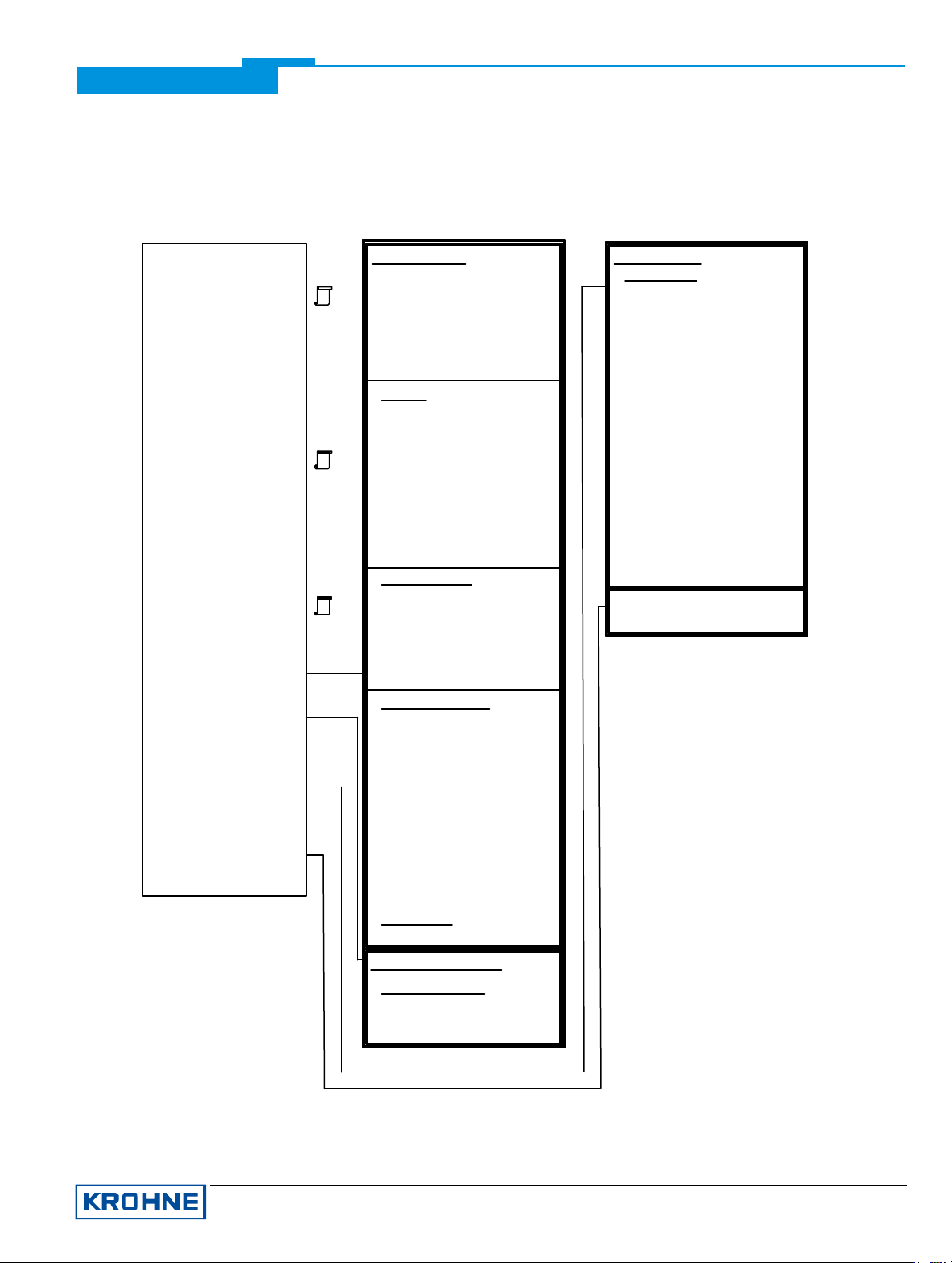
Supplementary documentation UFC030 with PROFI BUS-PA
UFC030 Menu Tree PDM
Parameter Table
Identification
Operation Unit
Device
Signal Converter
-----------------------------------
Mask Bits for Diagnosis
Opt
-----------------------------------
Input
Low Flow Cutoff
Measuring Limits
Operation Parameter
-----------------------------------
Output
FB1: AI - channel
FB2: AI - channel
FB3: TOT-channel
FB4: AI - channel
FB5: TOT-channel
Opt
Opt
Local In-/Outputs
-----------------------------------
Mechanical Construction
Process Connection
-----------------------------------
Human Interface
Local Display
-----------------------------------
Certificates and Approvals
• Static Revision No.
4
• Full Scale Units
• Full Scale
• Master Time Constant
• VOS Units
• Min VOS
• Max VOS
Opt
Version
• Temperature Units
• Input 1 4mA
• Input 1 20mA
4
• Pressure Units
• Input 2 4mA
• Input 2 20mA
Opt
• K0
Opt
• K1
Opt
• K2
• Density
Opt
Current Output I
• Function I
5
• Direction I
• Range I
Opt
• I 0%
• I 100%
• Limit
Opt
Opt
Frequency Output F
• Function F
• Direction F
• Digital Output
• Trip Point 1
• Trip Point 2
• Time Constant
• Output
• Pulsrate Units
• Pulsrate
Opt
Opt
• Units Pulse/Unit
• Pulse/Unit
• Pulsewidth
Digital Input
Rd
Local Display
• Language
• Entry Code
• Code 1
• Location
• Unit Text
• Unit Volume
• Unit Time
Opt
Opt
Opt
Opt
Opt
Opt
• Enable Reset
• Display Flow
• Function Totalizer
• Display Totalizer
• Volume Totalizer Units
• Energy Totalizer Units
• VOS
• Cyclic Display
• Error Messages
Opt
• Date
• Analog Input
Opt
Opt
Opt
Opt
Opt
Opt
Opt
Opt
Opt
Opt
Opt
Opt
Opt
• Gain
Certificates and Approvals
• Device Certification
Rd
• Function C
Human InterfaceLocal In -/Outputs
Designations:
Opt
Optional, dependent on device
implementation / configuration
Rd
Read-only
Loc
Local PDM,
affects only PDM views
KROHNE Messtechnik GmbH & Co. KG · Ludwig-Krohne-Str. 5 D-47058 Duisburg 17/17
Tel.: 0203-301 309 Fax: 0203-301389 · e-mail: [email protected]
Mechanical Construction
Process Connection
• Meter Size Table
• Meter Size Units
Opt
Opt
• Meter Size
KROHNE UFC030 PA 45f50001 (6/6)
09.03
 Loading...