


 Loading...
© KROHNE 06/2005 |
DIN A4: 7.10028.31.00 |
|
|
|
|
|
|
|
|
|
|
|
|
|
|||
7.30934.32.00 |
|
|
|
|
|
|
|
|
|
|
|
|
|
|
|
||
|
|
|
|
|
|
|
|
|
 GR
GR
Short form installation and operating instructions
Universal 3-Beam ultrasonic flowmeter
UFM 3030 ultrasonic flowmeter
UFC 030 ultrasonic flow converter
UFS 3000 ultrasonic flow sensor
Electromagnetic flowmeters
Variable area flowmeters
Mass flowmeters
Ultrasonic flowmeters
Vortex flowmeters
Flow controllers
Level measuring instruments
Pressure and temperature
Heat metering
Communications technology
Switches, counters, displays and recorders
Engineering systems & solutions
Subject to change without notice.
General advice on safety
•Do not install, operate or maintain this flowmeter without reading, understanding and following the factory-supplied instructions, otherwise injury or damage may result.
•Read these instructions carefully before starting installation and save them for future reference.
•Observe all warnings and instructions marked on the product.
•Use only mains supply with protective earthing connected.
•Do not use the product with removed covers under wet conditions.
•Consider handling and lifting instructions to avoid damage.
•Install the product securely and stable.
•Install and connect cabling proper to exclude damage or harmful situations.
•If the product does not operate normally, refer to the service instructions or refer to qualified KROHNE service engineers.
•There are no operator-serviceable parts inside the product.
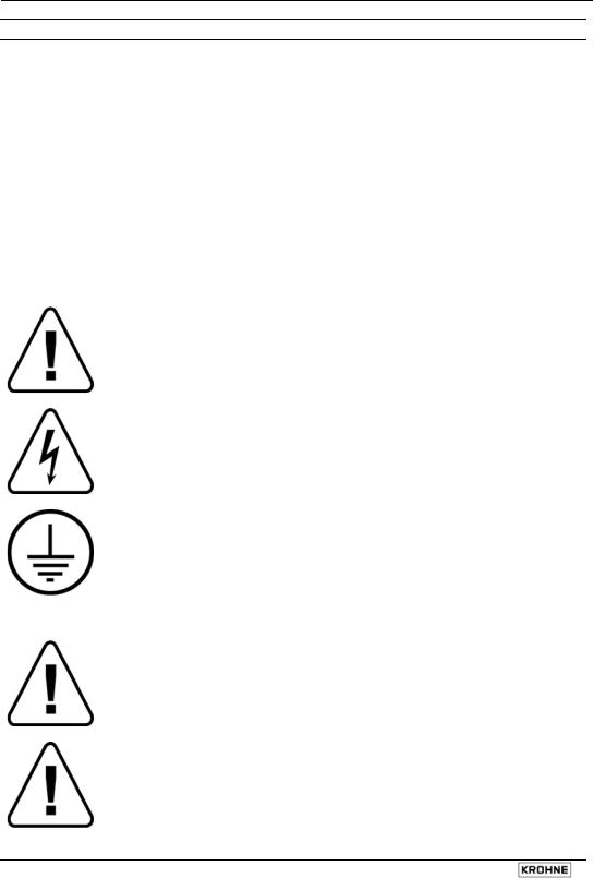
The following symbols may appear in this manual or on the product
ATTENTION: refer to operating and installation instructions!
DANGER: risk of electric shock!
PROTECTIVE conductor terminal!
These terms may appear in this manual or on the product:
WARNING statement: identify conditions or practice that could result in injury or loss of life.
CAUTION statement: identify conditions or practice that could result in damage to the product or other property.
2 |
UFM 3030 |
Disclaimer
•This document contains important information on the product. KROHNE attempts to be as accurate and up-to-date as possible but assumes no responsibility for errors or omissions. Nor does KROHNE make any commitment to update the information contained herein. This manual and all other documents are subject to change without prior notice.
•KROHNE will not be liable for any damage of any kind by using its product, including, but not limited to direct, indirect, incidental, punitive and consequential damages.
•This disclaimer does not apply in case KROHNE has acted on purpose or with gross negligence. In the event any applicable law does not allow such limitations on implied warranties or the exclusion of limitation of certain damages, you may, if such law applies to you, not be subject to some or all of the above disclaimer, exclusions or limitations.
•Any product purchased from KROHNE is warranted in accordance with the relevant product documentation and our Terms and Conditions of Sale.
•KROHNE reserves the right to alter the content of its documents, including this disclaimer in any way, at any time, for any reason, without prior notification, and will not be liable in any way for possible consequences of such changes.
Product liability and warranty
•Responsibility for suitability and intended use of this ultrasonic flowmeter rests solely with the user. Improper installation and operation of the flowmeter (system) may lead to loss of warranty.
•In addition, the Terms and Conditions of Sale are applicable and are the basis for the purchase contract.
•If flowmeters need to be returned to KROHNE, please note the information given on the last pages of the installation and operating instructions. KROHNE regrets that they cannot repair or check flowmeter(s) unless accompanied by the completed form (see last pages of the installation and operating instructions).
Items included with order
•UFM 3030 ultrasonic flowmeter, comprising of a flow sensor, UFS3000 and a signal converter, UFC 030 either built together as a compact system or supplied as two separate pieces, in the size as indicated on the packaging box
•Signal cable (only in case of a separate system)
•Special tool for opening the converter housing
Documentation supplied
•Condensed installation and operating manual
•For Ex-units: installation and operating instructions for use in hazardous areas
•Service Handbook
•Approval documents, unless reproduced in the installation and operating instructions
•Report of factory settings of the signal converter
•Certificate of system calibration data
UFM 3030 |
3 |
System Installation and Start-up
1 Introduction
1.1Cautions
Only for flowmeters supplied with a voltage over 50 VAC.
Refer all maintenance or service to trained KROHNE service engineers.
Mains power shall be disconnected from the product before performing any maintenance.
This product is prepared for and can only function with the rated AC mains or DC supply voltage as indicated on the nameplate.
For 100 – 240 VAC supplied flowmeters: this product is a Class 1 device (earthed) and requires a correct connection to protective earth. The protective earth conductor of the main power shall be properly connected to the marked protective earth terminal to ensure safety from electric shock for the operator and its environment. For detail refer to this service handbook.
1.2Unpacking and inspection
•This product has been thoroughly inspected and tested before shipment and is ready for operation.
•After carefully unpacking, inspect for shipping damage before attempting to operate. If any indication of mechanical damage is found contact immediately the responsible transport service and your local KROHNE representative.
•A simple operating check of the electronics after unpacking and before permanent installation is advisable to ascertain whether it has suffered damage during shipment. Confirm for the correct mains voltage printed on the nameplate. If it differs from the ordered product please contact your local KROHNE representative.
•After connecting to the mains, check if there is any indication on the display and if the backlight of the display is lighted. If not, contact your local KROHNE representative for advice.
1.3System description
The UFM 3030 ultrasonic flowmeter is a precision instrument designed for linear, bi/directional flow measurement of liquids. Flow measurement values can be output via the standard analog and-or pulse/frequency outputs. Via a user friendly operator interface (HMI) the unit can be set up for a wide range of applications. Next to actual volumetric flow measurement the unit can be configured to perform flow totalization (plus, minus and sum). Also measurement and output of the liquid sonic velocity can be configured. Optionally the unit can be set to perform one of the following additional functions:
•Calculate and output corrected standard volumetric or mass flow using the external pressure and temperature inputs
•Batching
•Heat measurement
4 |
UFM 3030 |
1.4CE Approvals
EMC, Electromagnetic Compatibility Directive
EMC directive 89/336/EEC.
Low Voltage Directive
73/23/EEC and is designed in accordance with EN IEC 61010-1 first and second edition.
Pressure Equipment Directive 97/23/EC / Module H
2 Mechanical Installation
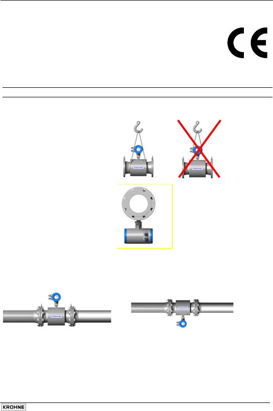
2.1Handling the flowmeter
Important: Do not lift the compact flowmeter by the signal converter housing or the terminal box. Check the weight of the flowmeter as indicated on the type plate before handling the unit. When handling the flowmeter avoid hard blows, jolts or impacts.
Do not place the flowmeter on the signal converter housing.
2.2Installation location and position
If required the position of the signal converter can be modified by turning the display through 90° or 180°
Keep measuring tube completely filled at all times for proper flow measurement. Non-wetted sensors
UFM 3030 |
5 |
show loss of signal. There is no damage when this occurs.
Flow direction. The UFM 3030 is a bi-directional flowmeter. Note the indicating arrow for the positive direction on the flowmeter.
In case of direct sunlight, we recommend installation of a sunshield to prolong the life of the meter. No direct damage will occur without a sunshield.
Do not expose the signal converter to excessive vibration. For this, support the pipeline on either side of the flowmeter.
To achieve the specified accuracy, ensure a straight inlet section of 10 × DN (DN = meter size) and an outlet section of 5 × DN.
Mixing different fluid products. Install the flowmeter upstream of mixing point or at minimum distance of 30× DN (DN = meter size) downstream of the mixing point, otherwise the flow measurement may be unstable.
Ambient temperature all flowmeters: Product temperature compact flowmeter: Product temperature separate flowmeter:
-40 to +65°C/ -40 to +149°F -25 to +140°C/ -13 F to +284°F -25 to +180°C/ -13 to +356°F
a minimum distance between pipe centreline and any adjacent wall of at least 0.5 m (1.6 ft).
2.3Special installation requirements
To avoid measuring errors and malfunctioning of the flowmeter due to gas or air inclusions or an empty pipe, please observe the following precautions:
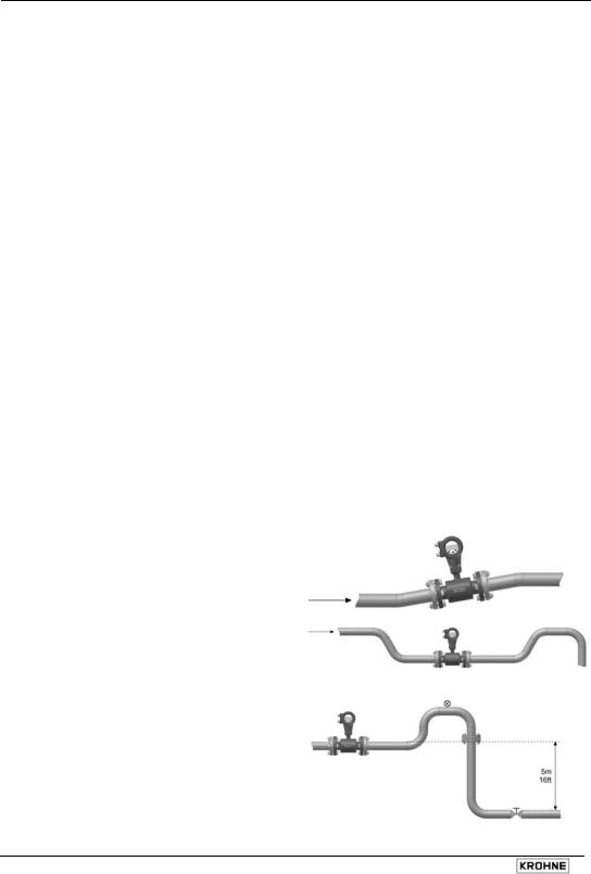
Since gas will collect at the highest point of a pipe, installation of the flowmeter at that location should be avoided at all times. Also installation in a down going pipe should be avoided since a completely filled pipe may not be guaranteed due to cascading affects. Additionally flow profile distortion is possible.
Long horizontal pipes:
install in slightly ascending pipe section. If not possible, ensure adequate velocity to prevent air, gas or vapour from collecting in upper part of flow tube As a partially filled meter will report higher than actual flow rates, or not measure (as transducer pairs become non-wetted).
Open feed or discharge:
Install meter in a lowered section of the pipe to ensure a full pipe condition through the meter.
Down going pipeline over 5 m (16 ft) length: install air vent downstream of the flowmeter to prevent vacuum. While this will not harm the meter, it may cause gases to come out of solution (cavitate) and interfere with proper measurements.
6 |
UFM 3030 |

Always install control valves downstream of flowmeter in order to avoid cavitation or distortion of flow profile.
Never install flowmeter on a pump suction side in order to avoid cavitation or flashing in the flowmeter.
2.4Pipe flanges
Refer to dimensional drawings for flange spacing and in addition allow for thickness of gaskets. Install flowmeter in line with pipe axis. Pipe flange faces must be parallel to each other, max. Permissible deviation: Lmax - Lmin ≤ 0.5 mm (0.02").
2.5Pipes with cathodic protection
Pipes with electric corrosion protection are generally insulated inside and outside so that the fluid has no conductive connection to ground. The flowmeter must be insulated from the pipe. Note the following when installing the flowmeter:
The pipe flanges must be connected to each other using a copper cable (L), but must not be connected to the flowmeter.
The bolts for the flange connections and the gaskets must be insulated. Use sleeves and washers that are made of insulating material (these must be provided by customer).
1.Flange of flow sensor
2.Pipe flange
3.Gasket
4.Bolt
5.Nut
6.Washer
7.Insulating sleeve
Follow grounding instructions.
Use ≥ 4 mm² (≥ AWG 10 cable).
Note: No earthing cables are supplied by KROHNE.
UFM 3030 |
7 |
Loading...