


 OPTIWAVE 5200 C/F Quick Start
2-wire / 10 GHz Radar (FMCW) Level Meter
for distance, level, volume, flow and reflection measurement of liquids, pastes and slurries
© KROHNE 08/2013 - 4001905202 - QS OPTIWAVE 5200 R02 en

|
CONTENTS |
OPTIWAVE 5200 C/F |
|
|
|
||
|
|
|
|
1 |
Safety instructions |
3 |
|
|
|
|
|
2 |
Installation |
4 |
|
|
|
|
|
|
2.1 |
Intended use ..................................................................................................................... |
4 |
|
2.2 |
Scope of delivery............................................................................................................... |
4 |
|
2.3 |
Visual Check ..................................................................................................................... |
5 |
|
2.4 |
Storage ............................................................................................................................. |
6 |
|
2.5 |
Transport .......................................................................................................................... |
6 |
|
2.6 |
Pre-installation requirements ......................................................................................... |
6 |
|
2.7 |
Installation........................................................................................................................ |
7 |
2.7.1 Pressure and temperature ranges......................................................................................... |
7 |
|
2.7.2 Recommended mounting position.......................................................................................... |
9 |
|
2.7.3 Mounting restrictions............................................................................................................ |
11 |
|
2.7.4 Standpipes (stilling wells and bypass chambers) ................................................................ |
16 |
|
2.7.5 Wall support for the remote version .................................................................................... |
16 |
|
2.7.6 How to attach an antenna extension (Metallic Horn or Wave Guide antennas)................... |
17 |
|
2.7.7 How to turn or remove the signal converter ........................................................................ |
19 |
|
2.7.8 How to attach the weather protection to the device............................................................. |
20 |
|
2.7.9 How to open the weather protection .................................................................................... |
23 |
|
3 Electrical connections |
24 |
|
|
|
|
3.1 |
Electrical installation: 2-wire, loop-powered ................................................................ |
24 |
3.1.1 Compact version ................................................................................................................... |
24 |
|
3.1.2 Remote version ..................................................................................................................... |
26 |
|
3.2 |
Non-Ex devices............................................................................................................... |
27 |
3.3 |
Devices for hazardous locations .................................................................................... |
27 |
3.4 |
Minimum power supply voltage ..................................................................................... |
28 |
3.5 |
Protection category ........................................................................................................ |
29 |
3.6 |
Networks ........................................................................................................................ |
30 |
3.6.1 General information.............................................................................................................. |
30 |
|
3.6.2 Point-to-point connection..................................................................................................... |
30 |
|
3.6.3 Multi-drop networks ............................................................................................................. |
31 |
|
3.6.4 Fieldbus networks................................................................................................................. |
32 |
|
4 Operation |
34 |
|
|
|
|
4.1 |
General notes ................................................................................................................. |
34 |
4.2 |
Digital display screen ..................................................................................................... |
34 |
4.2.1 Local display screen layout .................................................................................................. |
34 |
|
4.2.2 Functions of keypad buttons................................................................................................. |
34 |
|
4.3 |
Quick Setup (Parameters) .............................................................................................. |
35 |
5 Notes |
|
37 |
|
|
|
2 |
www.krohne.com |
08/2013 - 4001905202 - QS OPTIWAVE 5200 R02 en |
|
|
SAFETY INSTRUCTIONS 1 |
|
OPTIWAVE 5200 C/F |
|
|
|
|
Warnings and symbols used
DANGER!
This information refers to the immediate danger when working with electricity.
DANGER!
These warnings must be observed without fail. Even partial disregard of this warning can lead to serious health problems and even death. There is also the risk of seriously damaging the device or parts of the operator's plant.
WARNING!
Disregarding this safety warning, even if only in part, poses the risk of serious health problems. There is also the risk of damaging the device or parts of the operator's plant.
CAUTION!
Disregarding these instructions can result in damage to the device or to parts of the operator's plant.
INFORMATION!
These instructions contain important information for the handling of the device.
HANDLING
•This symbol designates all instructions for actions to be carried out by the operator in the specified sequence.
iRESULT
This symbol refers to all important consequences of the previous actions.
Safety instructions for the operator
CAUTION!
Installation, assembly, start-up and maintenance may only be performed by appropriately trained personnel. The regional occupational health and safety directives must always be observed.
LEGAL NOTICE!
The responsibility as to the suitability and intended use of this device rests solely with the user. The supplier assumes no responsibility in the event of improper use by the customer. Improper installation and operation may lead to loss of warranty. In addition, the "Terms and Conditions of Sale" apply which form the basis of the purchase contract.
INFORMATION!
•Further information can be found in the handbook and on the data sheet. These documents can be downloaded from the website (Download Center).
•If you need to return the device to the manufacturer or supplier, please fill out the device return form and send it with the device. Unfortunately, the manufacturer cannot repair or inspect the device without the completed form. The form can be found in the handbook or downloaded from the website. Click on the "Service" tab on one of the web pages and read the instructions.
08/2013 - 4001905202 - QS OPTIWAVE 5200 R02 en |
www.krohne.com |
3 |
2 INSTALLATION |
OPTIWAVE 5200 C/F |
|
2.1 Intended use
CAUTION!
Responsibility for the use of the measuring devices with regard to suitability, intended use and corrosion resistance of the used materials against the measured fluid lies solely with the operator.
INFORMATION!
The manufacturer is not liable for any damage resulting from improper use or use for other than the intended purpose.
This radar level transmitter measures distance, level, mass, volume, flow rate (in open channels) and reflectivity of liquids, pastes and slurries. It does not touch the measured product.
2.2 Scope of delivery
INFORMATION!
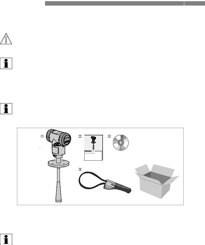
Do a check of the packing list to make sure that you have all the elements given in the order.
Figure 2-1: Scope of delivery
1Signal converter and antenna (compact version)
2Quick Start
3Strap wrench
4DVD-ROM (including Handbook, Quick Start, Technical Datasheet and related software)
INFORMATION!
METALLIC HORN AND WAVE GUIDE ANTENNAS
If the device has an antenna extension option, this part is attached to the device if the antenna extension length, Lext ≤ 300 mm / 11.8¨. If Lext > 300 mm / 11.8¨, then the antenna extension is not attached to the device. Obey the assembly procedure on page 17.
4 |
www.krohne.com |
08/2013 - 4001905202 - QS OPTIWAVE 5200 R02 en |
|
|
INSTALLATION 2 |
|
OPTIWAVE 5200 C/F |
|
|
|
|
2.3 Visual Check
INFORMATION!
Inspect the cartons carefully for damages or signs of rough handling. Report damage to the carrier and to the local office of the manufacturer.
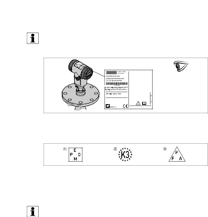
Figure 2-2: Visual check
1Device nameplate (for more data, refer to the handbook)
2Process connection data (size and pressure rating, material reference and heat number)
3Gasket material data - refer to the illustration that follows
Figure 2-3: Symbols for the supplied gasket material (on the side of the process connection)
1EPDM
2Kalrez® 6375
3PFA
If the device is supplied with an FKM/FPM gasket, there is no symbol on the side of the process connection.
INFORMATION!
Look at the device nameplate to ensure that the device is delivered according to your order. Check for the correct supply voltage printed on the nameplate.
08/2013 - 4001905202 - QS OPTIWAVE 5200 R02 en |
www.krohne.com |
5 |
2 INSTALLATION |
OPTIWAVE 5200 C/F |
|
2.4 Storage
WARNING!
Do not keep the device in a vertical position. This will damage the antenna and the device will not measure correctly.
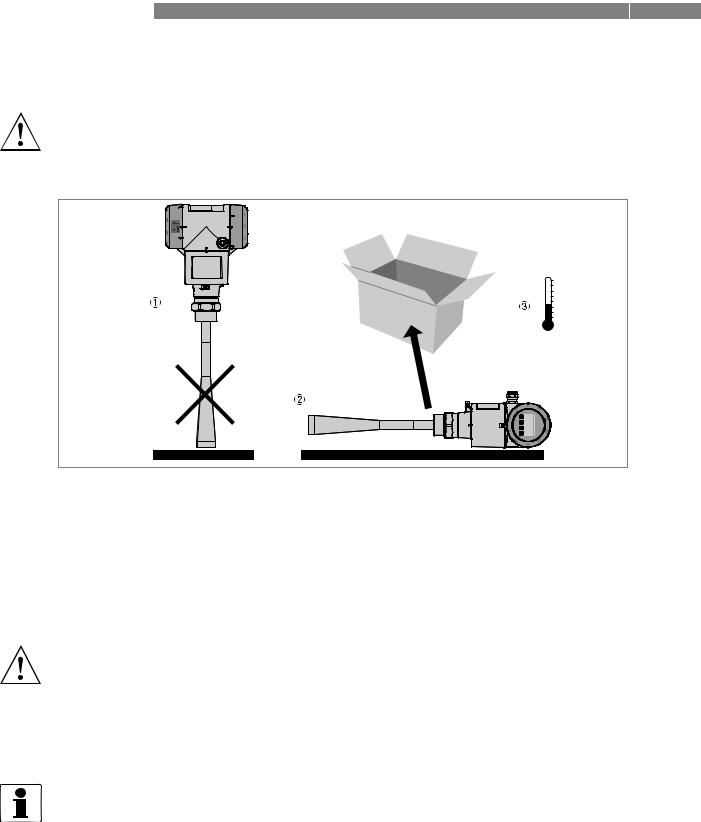
Figure 2-4: Storage conditions
1When you put the device into storage, do not keep it in a vertical position
2Put the device on its side. We recommend that you use the packaging in which it was delivered.
3Storage temperature range: -40...+80°C / -40...+176°F
•Store the device in a dry and dust-free location.
•Store the device in its original packing.
2.5Transport
WARNING!
• Depending on the version, the device will weight approx. 5...30 kg / 11...66 lbs. To carry, use both hands to lift the device carefully by the converter housing. If necessary, lift the device with a hoist.
•When handling the device, avoid hard blows, jolts, impact, etc. to prevent damage.
2.6Pre-installation requirements
INFORMATION!
Obey the precautions that follow to make sure that the device is correctly installed.
•Make sure that there is sufficent space on all sides.
•Protect the signal converter from direct sunlight. The device has a weather protection option.
•Do not subject the signal converter to heavy vibrations.
6 |
www.krohne.com |
08/2013 - 4001905202 - QS OPTIWAVE 5200 R02 en |
|
|
INSTALLATION 2 |
|
OPTIWAVE 5200 C/F |
|
|
|
|
2.7 Installation
2.7.1 Pressure and temperature ranges
DANGER!
If the ambient temperature is more than +70°C / +158°F, there is a risk of injury if you touch the device. Use a protective cover or metallic grid to prevent injury.
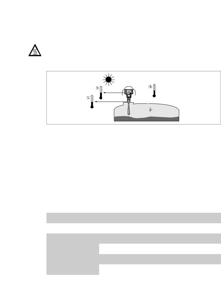
Figure 2-5: Pressure and temperature ranges
1Flange temperature
Non-Ex devices: Depends on the type of antenna, process connection and the seal material. Refer to the table that follows.
Ex devices: see supplementary operating instructions
2Ambient temperature for operation of the display -20...+60°C / -4...+140°F
If the ambient temperature is not between these limits, the display screen switches off automatically. The device continues to operate.
3Ambient temperature
Non-Ex devices: -40...+80°C / -40...+176°F
Ex devices: see supplementary operating instructions
4Process pressure
Depends on the type of antenna and process connection. Refer to the table that follows.
Antenna type |
Process |
Seal |
Process connection |
Process pressure |
||||||
|
connection |
|
|
temperature |
|
|
|
|
|
|
|
|
|
|
|
|
|
||||
|
|
|
[°C] |
[°F] |
[barg] |
[psig] |
||||
|
|
|
|
|
|
|
|
|
|
|
PP |
G 1½; |
- |
-20... |
+100 |
-4... |
+212 |
-1... |
16 |
-14.5... |
232 |
Wave Horn |
1½ NPT |
|
|
|
|
|
|
|
|
|
PTFE |
Flange with |
- |
-50... |
+150 |
-58... |
+302 |
-1... |
40 |
-14.5... |
580 |
Wave Horn |
PTFE plate |
|
|
|
|
|
|
|
|
|
|
|
|
|
|
|
|
|
|
|
|
Metallic Horn |
Flange |
Metaglas® with |
-40... |
+200 |
-40... |
+392 |
-1... |
40 |
-14.5... |
580 |
Wave Guide |
|
FKM/FPM |
|
1 |
|
1 |
|
2 |
|
2 |
|
|
|
|
|
|
|
|
|
|
|
|
|
Metaglas® with |
-20... |
+250 |
-4... |
+482 |
-1... |
40 |
-14.5... |
580 |
|
|
Kalrez® 6375 |
|
1 |
|
1 |
|
2 |
|
2 |
|
|
Metaglas® with |
-60... |
+130 |
-76... |
+266 |
-1... |
40 |
-14.5... |
580 |
|
|
PFA |
|
1 |
|
1 |
|
2 |
|
2 |
|
|
|
|
|
|
|
|
|
|
|
|
|
Metaglas® with |
-50... |
+130 |
-58... |
+266 |
-1... |
40 |
-14.5... |
580 |
|
|
EPDM |
|
1 |
|
1 |
|
2 |
|
2 |
|
|
|
|
|
|
|
|
|
|
|
1Higher temperature on request
2Higher pressure on request
For more data on pressure ratings, refer to the "Technical Data" chapter in the handbook.
08/2013 - 4001905202 - QS OPTIWAVE 5200 R02 en |
www.krohne.com |
7 |

2 INSTALLATION |
OPTIWAVE 5200 C/F |
|
Ambient temperature / flange temperature, flange and threaded connection, in °C
Figure 2-6: Ambient temperature / flange temperature, flange and threaded connection, in °C
Ambient temperature / flange temperature, flange and threaded connection, in °F
Figure 2-7: Ambient temperature / flange temperature, flange and threaded connection, in °F
1Maximum ambient temperature, °C
2Maximum flange temperature, °C
3Maximum ambient temperature, °F
4Maximum flange temperature, °F
5PP Wave Horn antenna
6PTFE Wave Horn antennas. Metallic Horn and Wave Guide antennas (standard temperature version).
7Metallic Horn and Wave Guide antennas (high temperature version)
There is no change (de-rating) in ambient temperature below 0°C / 0°F. The process connection temperature must agree with the temperature limits of the gasket material. For pressure rating data, refer to the "Technical Data" chapter in the Handbook.
8 |
www.krohne.com |
08/2013 - 4001905202 - QS OPTIWAVE 5200 R02 en |
|
|
INSTALLATION 2 |
|
OPTIWAVE 5200 C/F |
|
|
|
|
2.7.2 Recommended mounting position
CAUTION!
Follow these recommendations to make sure that the device measures correctly. They have an effect on the performance of the device.
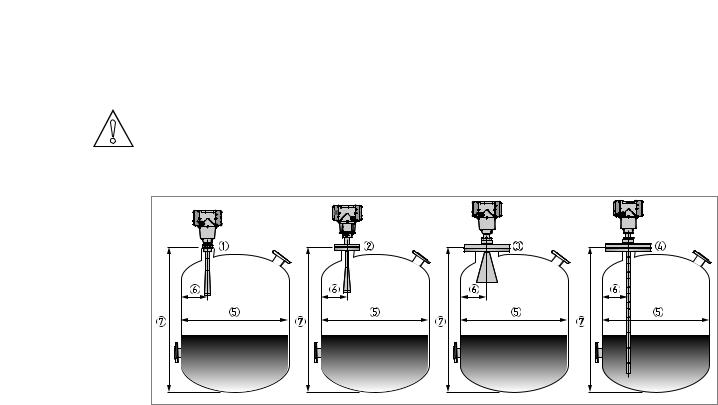
Figure 2-8: Recommended mounting position for liquids, pastes and slurries
1Sockets for the PP Wave Horn antenna
2Nozzles for the PTFE Wave Horn antenna
3Nozzles for DN150 or DN200 Metallic Horn antennas
4Nozzles for Wave Guide antennas
5Tank diameter
6Minimum distance of the nozzle or socket from the tank wall (depends on the antenna type and size - refer to items 1, 2 , 3 and 4 in this list):
-PP/PTFE Wave Horn (1 and 2): 1/7 × tank height
-Metallic Horn (3): 1/10 × tank height
-Wave Guide (4): There is no minimum distance from the Wave Guide antenna to metallic walls and other metal objects
Maximum distance of nozzle from the tank wall (depends on the antenna type and size - refer to items 1, 2 and 3 in this list):
-PP/PTFE Wave Horn (1 and 2): 1/3 × tank diameter
-Metallic Horn (3): 1/3 × tank diameter
-Wave Guide (4): There is no maximum distance from the Wave Guide antenna to metallic walls and other metal objects
7 Tank height
08/2013 - 4001905202 - QS OPTIWAVE 5200 R02 en |
www.krohne.com |
9 |
2 INSTALLATION |
OPTIWAVE 5200 C/F |
|
Point the device in the correct direction
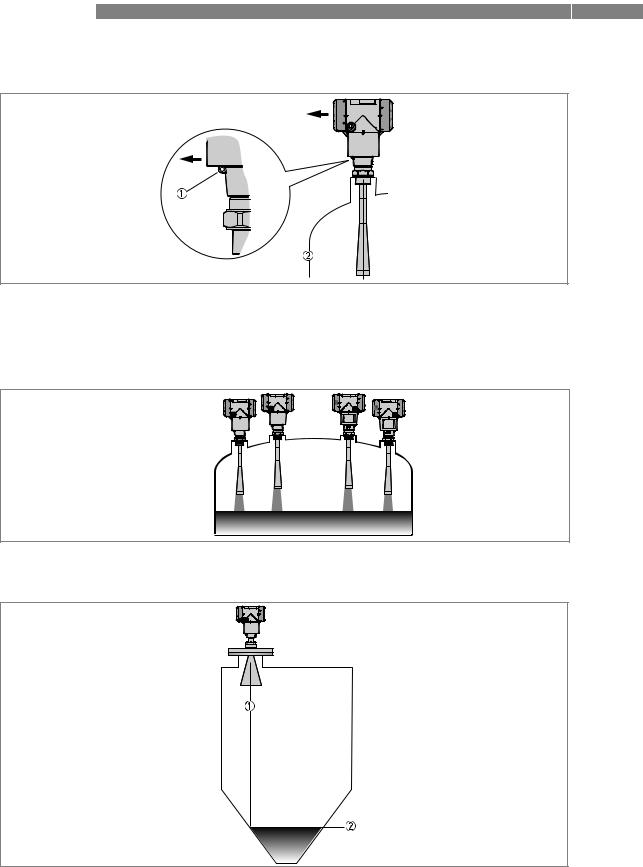
Figure 2-9: Point the device in the correct direction to get the best performance
Point the tag hole on the housing in the direction of the nearest tank wall.
1Tag hole
2Nearest tank wall
Figure 2-10: A maximum of 4 FMCW radar level meters can be operated in a tank
Figure 2-11: Tanks with conical bottoms
Conical bottoms have an effect on the measuring range. The device cannot measure to the bottom of the tank.
1Axis of radar beam
2Minimum level reading
10 |
www.krohne.com |
08/2013 - 4001905202 - QS OPTIWAVE 5200 R02 en |
|
|
INSTALLATION 2 |
|
OPTIWAVE 5200 C/F |
|
|
|
|
2.7.3 Mounting restrictions
CAUTION!
Follow these recommendations to make sure that the device measures correctly. They have an effect on the performance of the device.
We recommend that you prepare the installation when the tank is empty.
Mounting restrictions: General data
Figure 2-12: Mounting restrictions: General data
1Do not tilt the device more than 2°
2We recommend that you do an empty spectrum recording if there are too many obstacles in the radar beam (refer to Operation). If necessary, install a bypass chamber or stilling well or use an "S" antenna extension or a "L" antenna extension (the device must be installed on the side of the tank) to move the device away from obstacles.
35 mm / 0.2¨ max. for high-dielectric constant liquids
4Beam radius (DN80 (3¨) Metallic Horn antenna): increments of 290 mm/m or 3.4¨/ft (16°) Beam radius (DN100 (4¨) Metallic Horn antenna): increments of 210 mm/m or 2.6¨/ft (12°) Beam radius (DN150 (6¨) Metallic Horn antenna): increments of 140 mm/m or 1.7¨/ft (8°)
Beam radius (DN200 (8¨) Metallic Horn antenna): increments of 100 mm/m or 1.3¨/ft (6°)
Beam radius (PP Wave Horn and PTFE Wave Horn antenna): increments of 176 mm/m or 2.1¨/ft (10°)
08/2013 - 4001905202 - QS OPTIWAVE 5200 R02 en |
www.krohne.com |
11 |
2 INSTALLATION |
OPTIWAVE 5200 C/F |
|
Obstacles in the tank
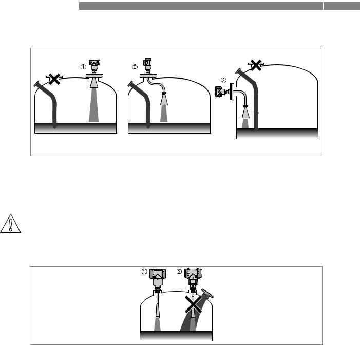
Figure 2-13: Obstacles in the tank
Do not put the device directly above obstacles (agitator, support beams, heating tubes etc.). Parasitic signals from obstacles will cause the device to measure incorrectly.
1Solution 1: Put the device on another process connection away from obstacles
2Solution 2: Use the same process connection, but also use an "S" extension
3Solution 3: Attach the device to the side of the tank and use an "L" (right angle) extension
CAUTION!
Do not put the device near to the product inlet. If the product that enters the tank touches the antenna, the device will measure incorrectly. If the product fills the tank directly below the antenna, the device will also measure incorrectly.
Figure 2-14: Product inlets
1The device is in the correct position.
2The device is too near to the product inlet.
12 |
www.krohne.com |
08/2013 - 4001905202 - QS OPTIWAVE 5200 R02 en |
 Loading...