


UFM 600T
KROHNE 01/94 7.30718.32.00
©
GR
Installation and
operating instructions
UFM 600 T
ALTOSONIC
Variable area flowmeters
Vortex flowmeters
Flow controllers
Electromagnetic flowmeters
Ultrasonic flowmeters
Mass flowmeters
Level measuring instruments
Communications engineering
Engineering systems & solutions
Switches, counters, displays and recorders
Heat metering
Pressure and temperature

All rights reserved. No part of this publication may be copied or published
by means of printing, photocopying, microfilm or otherwise without prior
written consent of KROHNE Altometer.
This restriction also applies to the corresponding drawings and diagrams.
KROHNE Altometer has the right to change the parts or specifications at
any time whitout prior or direct notice to the client. The contents of this
publication are subject to change without notice.
This publication is to be used for the standard version only. Thus KROHNE
Altometer cannot held responsible for any damage resulting from the
incorrect application of this publication to the version actually delivered to
you.
For additional information regarding configuration, maintenance and repair,
contact the technical department of your supplier.
This publication has been written with great care. However, KROHNE
Altometer cannot be held responsible, either for any errors occuring in this
publication or their consequences.
PM 04.97.Rev.3

ALTOSONIC
A INTRODUCTION ................................................................6
B SYSTEM DESCRIPTION ................................................. 8
B.1 Measuring Principle ........................................................... 8
B.2 Measuring System............................................................. 10
B.3 Equipment......................................................................... 12
B.4 Controls and Connections ................................................. 14
B.5 Transducers and Mountings ............................................. 16
B.6 Display and Data Storage .................................................. 17
B.7 Direct Output..................................................................... 18
B.8 Power Supply.................................................................... 18
C OPERATION .................................................................... 20
C.1 Initial Set-Up...................................................................... 20
C.1.1 Installation of mounting rails............................................... 21
C.1.2 Programming the application parameters .......................... 24
C.1.3 Installation of the transducers ............................................ 26
C.1.4 Zero set / zero point calibration ......................................... 28
C.2 Start Up Menu................................................................... 30
C.2.1 Enter start up menu........................................................... 30
C.2.2 Application Functions ........................................................ 30
C.2.3 Plausibility check ............................................................... 34
C.3 Error Detection .................................................................. 35
C.3.1 Low signal marker function................................................ 35
C.3.2 Error messages ................................................................. 36
C.4 Data Collection.................................................................. 38
C.4.1 Data collection procedure.................................................. 38
C.4.2 Transfer to PC (data and parameters)................................ 40
C.4.3 Parameter handling ........................................................... 41
C.5 Quit / Reset Menu ............................................................. 42
C.6 Direct Output Ports ........................................................... 44
C.6.1 General ............................................................................. 44
C.6.2 Output hold ....................................................................... 44
C.6.3 Current output................................................................... 44
C.6.4 Frequency output .............................................................. 44
C.6.5 Connection diagrams .......................................................45a
C.7 Trouble Shooting............................................................... 46
UFM 600 T
2
Contents

D PROGRAMMING MODE................................................. 48
D.1 General ............................................................................. 48
D.2 How to Program................................................................ 49
D.3 List of Functions ................................................................ 52
D.4 Main Menu: 3.0.0 INSTALLATION .................................... 54
D.5 Main Menu: 2.0.0 TEST..................................................... 72
D.6 Parameter errors ............................................................... 74
E MAINTENANCE............................................................... 76
E.1 Fuse .................................................................................. 76
F TECHNICAL DATA.......................................................... 78
F.1 General ............................................................................. 78
F.2 Transducers & Clamp-on Set ............................................ 79
F.3 Signal Converter ................................................................ 80
APPENDIX 1 : Pipe Material Sonic Velocities .................. 84
APPENDIX 2 : Sonic Velocities of Liquids ....................... 85
APPENDIX 3 : Sonic Velocity Calculation........................ 86
APPENDIX 4 : Exponential Notation.................................87
APPENDIX 5 : Default Settings + Example of
Output Parameters .................................. 88
APPENDIX 6 : Spare Parts ............................................. 90
3
A
B
C
D
E
F

Fig. B.1 : Measuring principle........................................................... 8
Fig. B.2 : System diagram................................................................ 11
Fig. B.3 : UFM 600 T with all equipment displayed........................... 13
Fig. B.4 : UFC 600 T converter ........................................................ 15
Fig. B.5 : Transducers and unit ........................................................ 16
Fig. C.1 : Mounting rail ..................................................................... 22
Fig. C.2 : Mounting rails fitted on the pipe ........................................ 22
Fig. C.3 : Mounting positions............................................................ 23
Fig. C.4 : Position of transducer and cable....................................... 26
Fig. C.5 : Upstream and downstream connections........................... 27
Fig. D.1 : Entering the programming mode....................................... 49
Fig. D.2 : Low flow cutoff ................................................................. 55
Fig. D.3 : Bi-directional flow (I).......................................................... 61
Fig. D.4 : Flow direction indication (I) ................................................ 61
Fig. D.5 : Positive flow (I) .................................................................. 61
Fig. D.6 : Negative flow and output (I)............................................... 61
Fig. D.7 : Bi-directional flow (F)......................................................... 63
Fig. D.8 : Flow direction indication (F) ............................................... 63
Fig. D.9 : Positive flow (F) ................................................................. 64
(I) current output
(F) frequency output
4
ALTOSONIC
List of illustrations
UFM 600 T

5
System Description
The Altosonic UFM 600 T is an ultrasonic flowmeter which can easily be
clamped on existing pipelines with inner diameters between 50 mm and
3000 mm (2" to 120") and pipe wall thicknesses up to 40 mm.
Measurement is performed obstructionless, without changing the existing
pipework and without any headloss.
The UFM 600 T is an economical solution for all kinds of flow measurements of liquids containing no or little solid particles or gas.
Examples are: cooling water, waste water, oil, acids, bases etc.
6
ALTOSONIC
Introduction
UFM 600 T
little bows welded
on the tube
Mounting strap
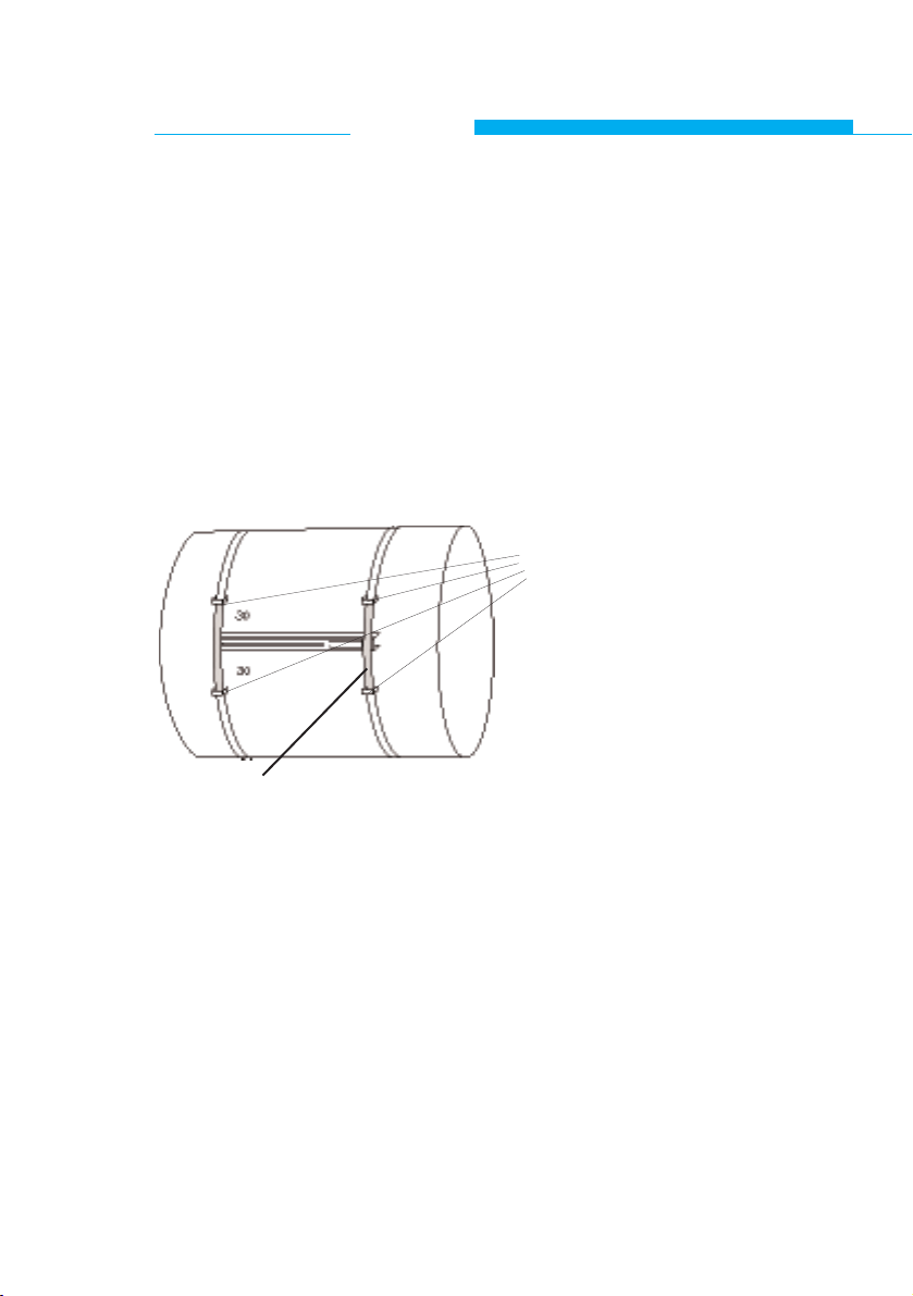
At mounting on diameters > DN 1600, we recommend to weld 4 little
bows on the tube as indicated in the sketch.
See also Chap. C.1.1.

7
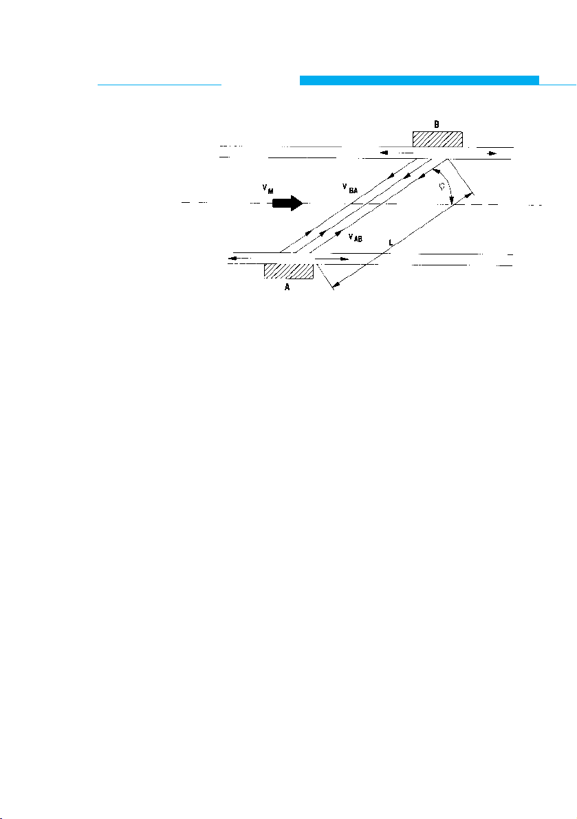
B.1 Measuring Principle
Fig. B.1 : Measuring principle
A sound wave that is sent in the direction of the flow through
a medium will travel faster than one that is sent in the opposite direction.
This principle is used in the ultrasonic transit time flowmeter.
Two ultrasound transmitters/receivers are fitted on opposite
sides of the pipe section as shown in Fig. B.1.
Initially transducer A transmits an ultrasonic sound signal that
will be received by transducer B. The time lapse tABbetween
transmission and reception is measured.
Then the functions of both probes are reversed and the transit time tBAin the opposite direction is measured.
From tABand t
BA
the actual flow can be calculated taking into
account the following factors:
- pipe diameter
- wall thickness
- lining thickness, if applicable
- sonic velocity in the liquid
- sonic velocity in the pipe material
- sonic velocity in the pipe lining material, if applicable
Measurements are taken continuously.
NOTE: Each transducer transmits and receives ultrasound signals.
8
ALTOSONIC
System Description
UFM 600 T

9

B.2 Measuring System
A microprocessor controls the transducers via an analog/
digital interface and calculates the actual flow.
The control program is stored in EPROM memory.
Parameters for the application and processing the data are
entered via the keyboard.
A liquid crystal display is used for the indication of all
measuring data.
All data collected in the field can be stored in RAM memory
and transferred to an IBM compatible PC via an RS 232 output; the same applies to the parameter settings.
Both current and frequency output signals are available for
auxiliary readout and/or control purposes.
Figure B.2 shows a diagram of the flowsystem.
10
ALTOSONIC
System Description
UFM 600 T
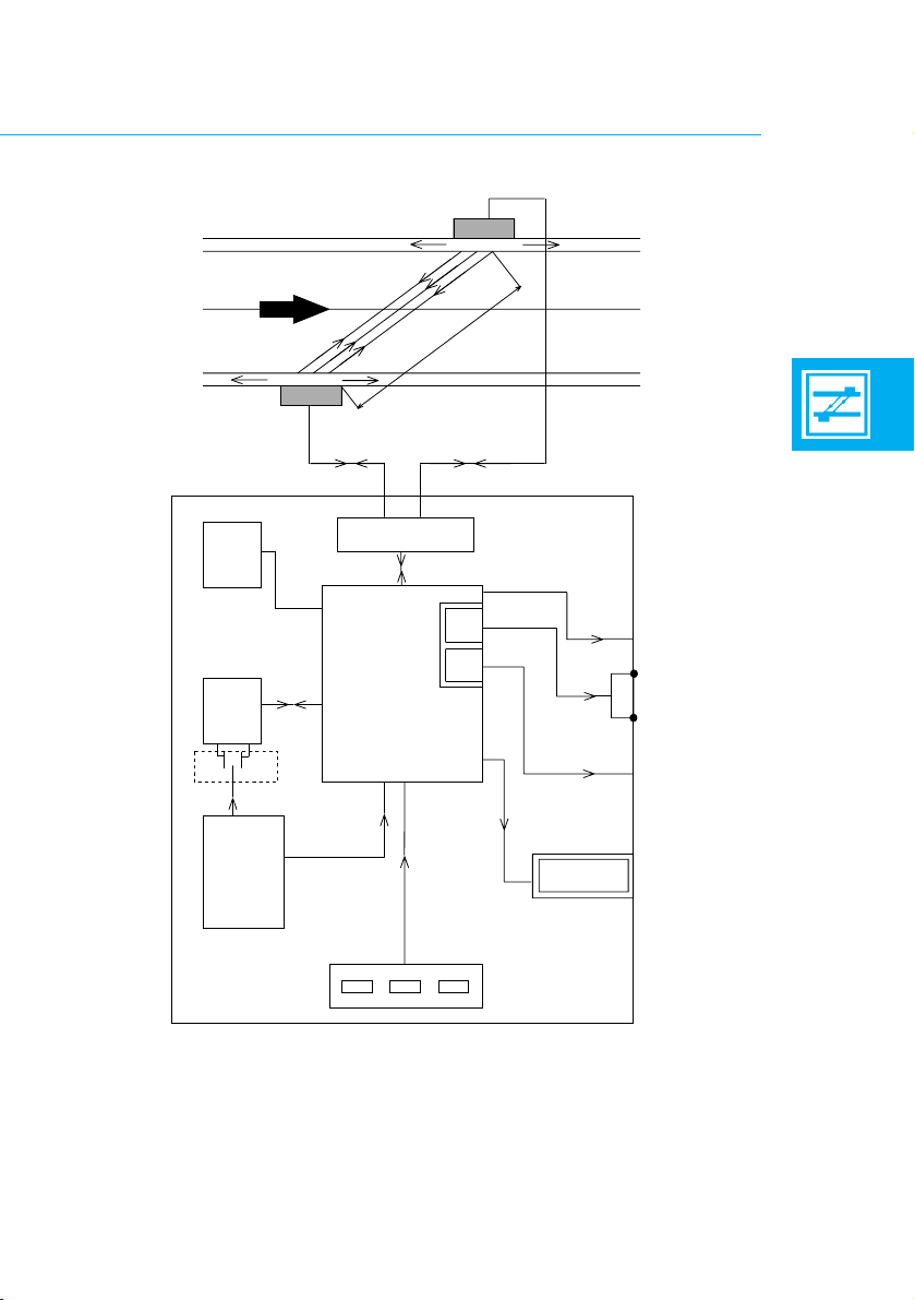
Fig. B.2 : System diagram
11
EEPROM
(µP1)
SENSOR
FLOW
SENSOR
UP DOWN
SIGNAL
PROCESSOR
RAM
POWER
SUPPLY
MICRO
PROCESSOR
(µP2)
KEYBOARD
RS 232 OUTPUT
CURRENT OUTPUT*
FREQUENCY*
OUTPUT
DISPLAY
*) galvanically insulated

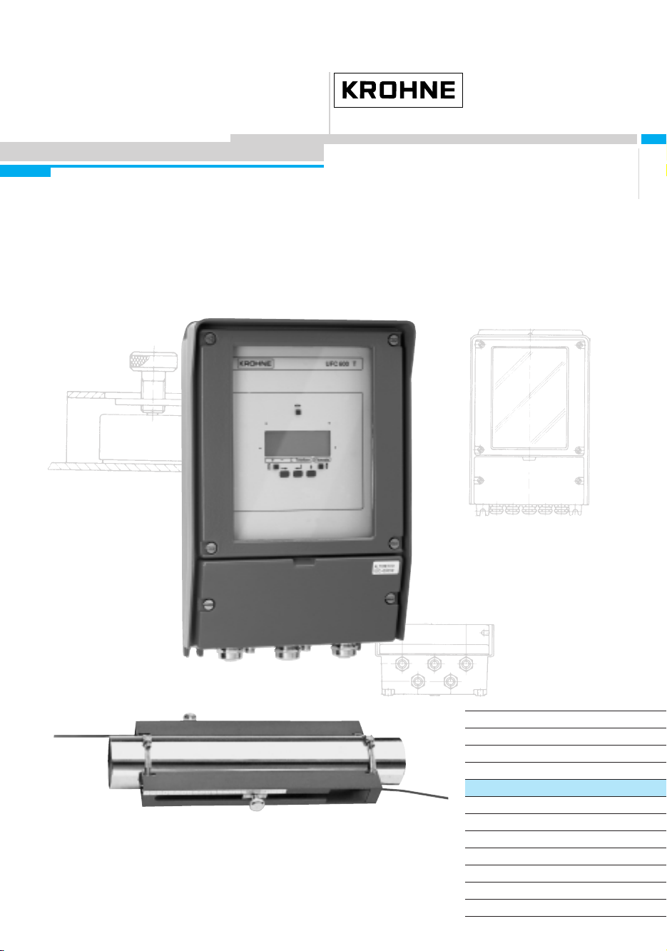
B.3 Equipment
The UFM 600 T flowmeter is fitted in a sturdy case.
Figure B.3 shows the UFM 600 T with all items
displayed:
1. UFC 600 T signal converter (1x)
2. RS 600 clamp on transducer (2x)
3. Shielded cable (coax) (2x)
4. Grounding cable (1x)
5. Small mounting strap (2x)
6. Large mounting strap (4x)
7. Mounting rail (2x)
8. Acoustic coupling grease (1x)
9. Measuring tape (5m) (1x)
- Manual and data sheets
- 3,5" diskette
10. Magnet bar (1x)
12
ALTOSONIC
System Description
UFM 600 T
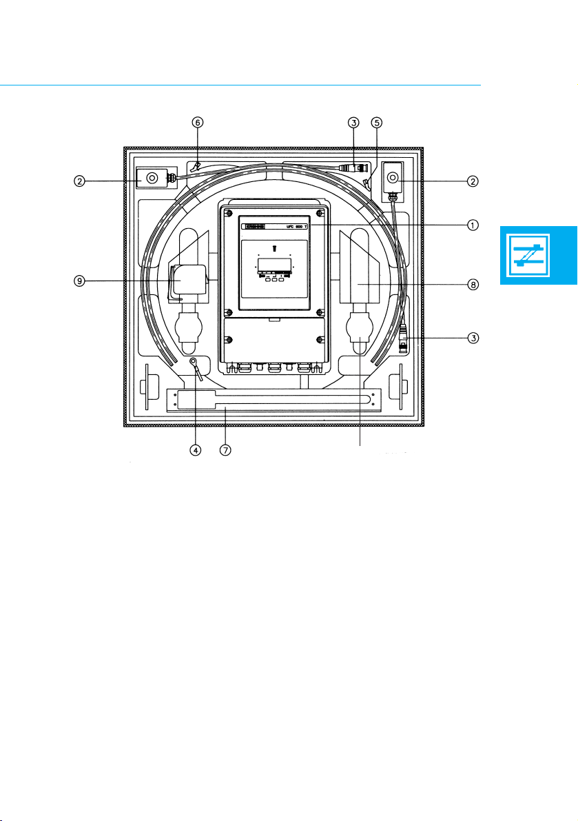
Fig. B.3 : UFM 600 T with all equipment displayed
13
➉

B.4 Controls and Connections
Figure B.4 shows the controls and connections of the
flowmeter unit.
1 Liquid crystal display
2 Keyboard (3 keys)
3 Power supply (term. 11,12)
4 Connector for upstream transducer
5 Connector for downstream transducer
6 RS 232 output for PC
7 mA-Output (term. 5, 6)
8 Frequency output (term. 4,.4.1, 4.2)
9 Hall contacts
14
ALTOSONIC
System description
UFM 600 T
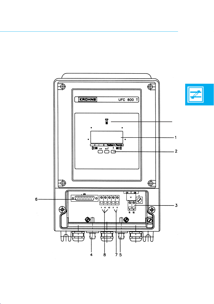
Fig. B.4 : UFC 600 T converter
15
9
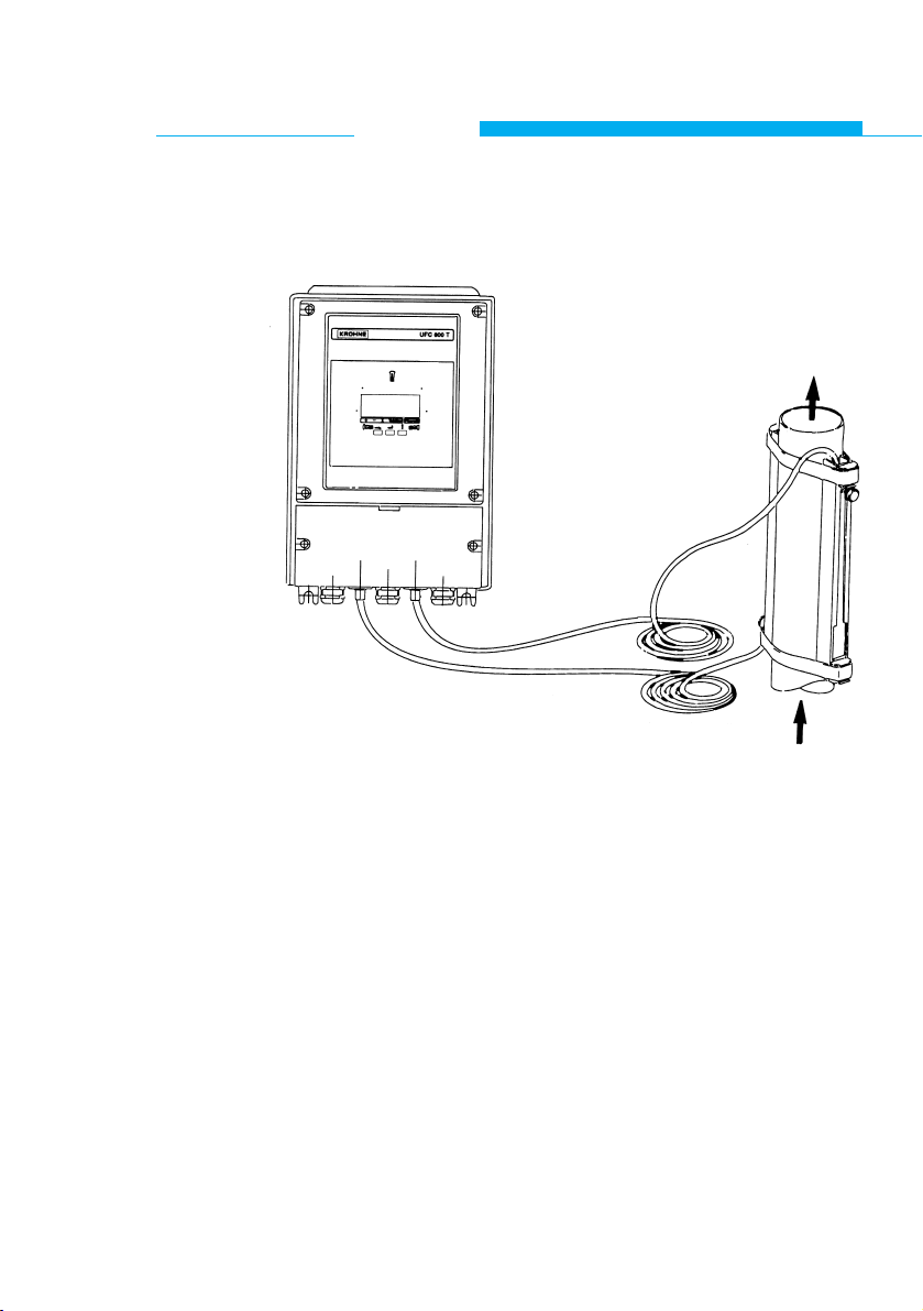
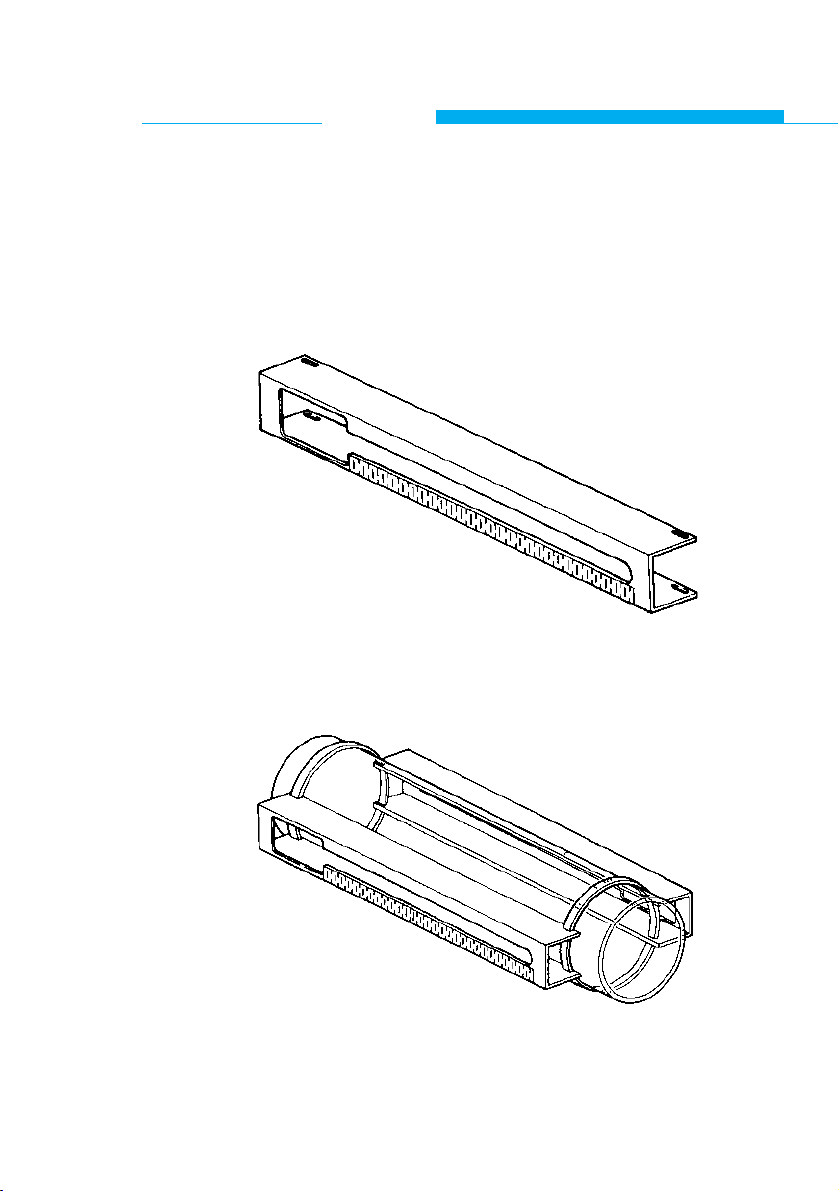
B.5 Transducers and Mountings (see Fig. B.5)
Fig. B.5 : Transducers, signal converter and auxillary items
Two mounting rails are clamped against the pipe wall by two
straps.
The transducers can slide inside the mounting rails to obtain
the correct distance between them. The transducers are then
tightened firmly against the pipe wall.
Coupling grease is used between the transducers and the
pipe wall to provide a good transfer of the ultrasound signal
through the pipe material.
The transducers are connected to the control unit by means
of two shielded cables.
16
ALTOSONIC
System description
UFM 600 T

B.6 Display and Data Storage
Display:
The following display options are available:
- Actual flow rate and direction.
- Total positive and negative flow volume since the
start of the measuring session.
- Absolute flow volume since the start of the
measuring session.
- Transit time of the acoustic signal.
- Error messages.
- Back lit function of the display.
Since the display shows only one read out at a time, they can
be viewed sequentially.
Collect data:
At a programmable interval, all flow information selected
to be displayed can be stored and sent to a PC via the
RS 232 output. Also the parameter settings can be send to a
PC.
17

B.7 Direct Output
Both current and frequency output signals are available for
control purposes. These can be either analog signals or just
flow direction indicator signals.
To avoid adverse effects on equipment connected to the
flowmeter a signal hold function can be activated; this is
important if the flowmeter is being used as part of a control
loop. When you terminate the measuring session the last
output signal can be maintained.
B.8 Power Supply
The flowmeter can be delivered in two versions for different
power sources:
- AC Power supply 85 - 264 VAC
- DC power supply 18 - 32 VDC
When the unit is switched off, the data stored in the volatile
memory is maintained by a backup battery on the microprocessor board.
This battery is capable of supporting the RAM for at least
5 years.
18
ALTOSONIC
System description
UFM 600 T

19

C.1 Initial Set-Up
The main steps of the installation procedure of the flowmeter
are:
1 Install the mounting rails on the pipe.
2 Program the application parameters through the
Start Up Menu, up to the point where the
microprocessor calculates the transducer distance.
3 Install the transducers in the mounting rails, according
to the microprocessor calculated distance.
4 If applicable perform a zero point calibration.
20
ALTOSONIC
Operation
UFM 600 T
C.1.1 Installation of mounting rails
Mounting Considerations:
The pipe section on which the transducers will be clamped
must always be completely filled with liquid, even if there is
no flow.
The transducers can be fitted on both horizontal and vertical
pipe sections (or any other elevation).
On horizontal pipes the transducers should be fitted such
that the ultrasonic pulse travels approximately horizontally
through the pipe since gas/vapour at the top of the pipe or
any contamination at the bottom can cause an obstruction to
the ultrasonic pulses.
The solid or gas content of the liquid must not exceed 1 percent by volume.
Note that, due to cavitation, bubbles can appear behind
valves, pumps etc., so the transducers should not be
installed too closely to these positions.
The absolute minimum distances are given in the table
below.
Highly distorted flow profiles may require significantly longer
straight upstream lengths.
Upstream straight length
- when mounted behind a pump ≥ 15 x DN
- when mounted behind a fully opened valve ≥ 10 x DN
- when mounted behind one or more elbows ≥ 10 x DN
- when mounted behind a reduction α/2,7° ≥ 5 x DN
Downstream straight length ≥ 5 x DN
(DN: Nominal Diameter)
21
Mounting Procedure:
a Severe rust or thick coatings have to be removed from
the pipe where the transducers will be installed.
b Slide the securing straps through the slots on both
ends of each mounting rail (see fig. C.1).
Fig. C.1 : Mounting rail
c Attach the rails on opposite sides of the pipe such that
the large slots point in opposite directions (see fig. C.2).
Fig. C.2 : Mounting rails fitted on the pipe
22
ALTOSONIC
Operation
UFM 600 T
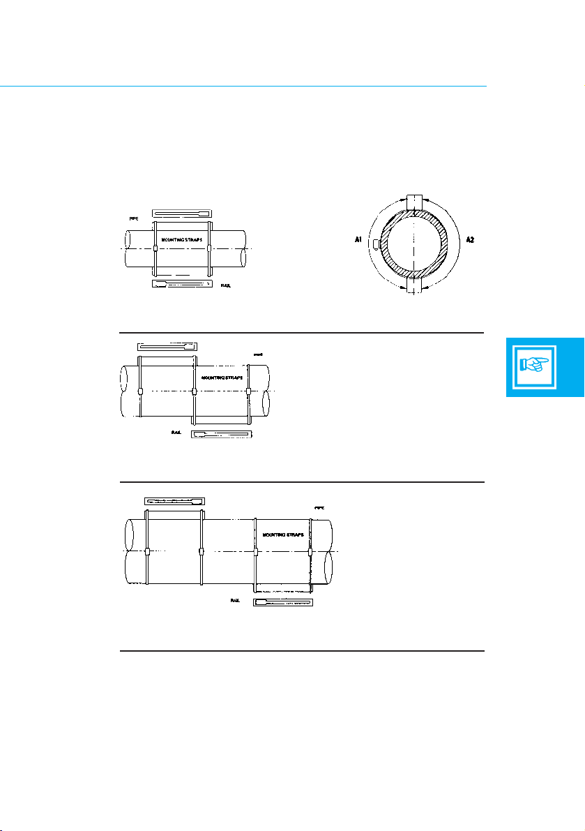
d Use the supplied tape measure to ensure that the rails
are fitted diametrically opposite each other
(see fig. C.3-1a. ).
Distance A1 must equal distance A2. Secure the rails by
tightening the straps.
Fig. C.3 : Mounting positions
23
1.
3.
1a.
Mounting position if calculated transducer distance does
not exceed 350 mm (14")
Mounting position if calculated transducer distance is
between 350 mm (14") and 700 mm (28")
2.
Mounting position if calculated transducer distance does
exceed ≥ 700 mm (28")
C.1.2 Programming the application parameters
After the flowmeter has been switched on it will start in the
measuring mode.
Pressing twice the key enters the Start Up Menu.
In this menu the application related parameters can be programmed.
All functions are described in section C.2.
Push Button Functions
The flowmeter can be programmed by means of the three
keys located below the liquid crystal display.
By pushing the left-hand key 'ARROW RIGHT' the
parameter shown on the display will be activated
and the desired value can be entered or an option
can be selected.
After pushing the key in the middle 'ENTER' the
programmed information will be stored and the
program advances to the next parameter.
For entering numbers or letters the 'ARROW UP'
key must be used; this will increment the ASCII
value of the blinking character (next higher number or next letter in the alphabet).
If a selection from a table must be made the
'ARROW UP' key can be used to display the next
option in the table. After using the 'ARROW UP'
key without actually programming a parameter the
next parameter will be displayed.
24
ALTOSONIC
Operation
UFM 600 T

Input of values
Input of values outside the range, indicated at the function
descriptions, will result in a flashing error message; the minimum or maximum value allowed is displayed above the error
message.
After pressing any key the function is active again and the
correct value can be entered.
Start Up Menu
Enter all application parameters in the Start Up Menu; see
section C.2 for full details. Continue until the transducer distance is on display. Now the transducers can be installed.
25
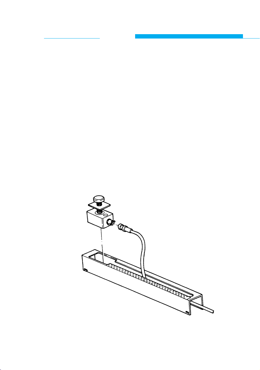
C.1.3 Installation of the transducers
Since the required transducer distance "S" is known now the
transducers can be positioned in the rails:
1 Turn the transducer securing screw completely counter
clockwise until the transducer positioning plate touches
the top of the transducer housing.
2 Feed the coax cables through both mounting rails.
3 Cover the bottom of both transducers with a thick layer of
the sonic coupling grease.
4 Connect each transducer to a coax cable and slide the
transducers into the rails (fig. C.4.) While inserting the
transducers, care must be taken not to touch the pipe
wall with the transducers before the proper position is
obtained, otherwise the coupling grease will be wiped off
the transducers and the result will be a bad sonic coupling between the transducers and the pipe wall.
Fig. C.4 : Position of transducer and cable
26
ALTOSONIC
Operation
UFM 600 T

27
NOTE: - The cable connections at the transducers must always
point away from each other (fig. C.5).
- Make sure that the transducers are not placed over a
welding seam.
Fig. C.5 : Upstream and downstream connection
5 Use the cm scale on the mounting rails to position
the transducers at the proper distance from each other
and hand tighten the securing screws.
6 Check using the indication of the low signal marker (see
C 3.1) whether the unit is functioning properly.
Continue with Zero Set function (C.1.4.)
NOTE: REMOVAL OF THE TRANSDUCERS FROM
PIPE WALL
When removing the transducers from the pipe wall, especially
after they have been in place for a long period, care should
be taken:
• Not to damage the tranducers by pulling strongly at the
securing screw.
• Therefore, to remove a tranducer, it must be removed in
a slicing motion. Do not just pull it straight off the pipe all !!
sensor distance S
FLOWDIRECTION
 Loading...